Embed Size (px)
Citation preview
DEVELOPMENT OF AERIAL-GROUND SENSING NETWORK:
ARCHITECTURE, SENSOR ACTIVATION, AND
SPATIAL PATH-ENERGY OPTIMIZATION
A DISSERTATION IN
Electrical and Computer Engineering
and
Engineering
Presented to the Faculty of the University of
Missouri - Kansas City in partial fulfillment of
the requirements for the degree
DOCTOR OF PHILOSOPHY
by
JIANFEI CHEN
B.S., Beijing University of Post and Communication, 2010
M.S., University of Missouri-Kansas City, 2013
Kansas City, Missouri
2019

© 2019
JIANFEI CHEN
ALL RIGHTS RESERVED
iii
DEVELOPMENT OF AERIAL-GROUND SENSING NETWORK:
ARCHITECTURE, SENSOR ACTIVATION, AND
SPATIAL PATH-ENERGY OPTIMIZATION
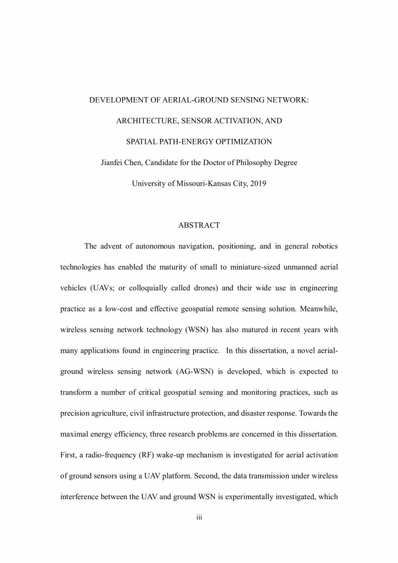
Jianfei Chen, Candidate for the Doctor of Philosophy Degree
University of Missouri-Kansas City, 2019
ABSTRACT
The advent of autonomous navigation, positioning, and in general robotics
technologies has enabled the maturity of small to miniature-sized unmanned aerial
vehicles (UAVs; or colloquially called drones) and their wide use in engineering
practice as a low-cost and effective geospatial remote sensing solution. Meanwhile,
wireless sensing network technology (WSN) has also matured in recent years with
many applications found in engineering practice. In this dissertation, a novel aerial-
ground wireless sensing network (AG-WSN) is developed, which is expected to
transform a number of critical geospatial sensing and monitoring practices, such as
precision agriculture, civil infrastructure protection, and disaster response. Towards the
maximal energy efficiency, three research problems are concerned in this dissertation.
First, a radio-frequency (RF) wake-up mechanism is investigated for aerial activation
of ground sensors using a UAV platform. Second, the data transmission under wireless
interference between the UAV and ground WSN is experimentally investigated, which

iv
suggests practical relations and parameters for aerial-ground communication
configuration. Last, this dissertation theoretically explores and develops an
optimization framework for UAV's aerial path planning when collecting ground-sensor
data. An improved mixed-integer non-linear programming approach is proposed for
solving the optimal spatial path-energy using the framework of the traveling-salesman
problem with neighborhoods.

v
APPROVAL PAGE
The faculty listed below, appointed by the Dean of the School of Graduate Studies, have
examined a dissertation titled “Development of Aerial-Ground Sensing Network:
Architecture, Sensor Activation, and Spatial Path-Energy Optimization”, presented by
Jianfei Chen, candidate for the Doctor of Philosophy degree, and certify that in their
opinion it is worthy of acceptance.
Supervisory Committee
ZhiQiang Chen, Ph.D., Committee Chair
Department of Civil and Mechanical Engineering
Ghulam Chaudhry, Ph.D., Department Chair
Department of Computer Science & Electrical Engineering
Cory Beard, Ph.D.
Department of Computer Science & Electrical Engineering
Yugyung Lee, Ph.D.
Department of Computer Science & Electrical Engineering
Ceki Halmen, Ph.D., P.E.
Department of Civil and Mechanical Engineering
Travis Fields, Ph.D.
Department of Civil and Mechanical Engineering

vi
CONTENTS
ABSTRACT ............................................................................................................. iii
ILLUSTRATIONS ................................................................................................. viii
TABLES ................................................................................................................... x
ACKNOWLEDGEMENTS ...................................................................................... xi
Chapter
1. INTRODUCTION ................................................................................................. 1
1.1 Motivation ....................................................................................................... 1
1.2 Energy Optimization for Sensor Network ......................................................... 4
1.3 Wireless Interference in AG-WSN ................................................................... 5
1.4 UAV Path Planning in AG-WSN ..................................................................... 7
2. DEVELOPMENT OF RADIO-FREQUENCY SENSOR WAKE-UP THROUGH
UAV AS AN AERIAL GATEWAY........................................................................ 10
2.1 Introduction ................................................................................................... 10
2.2 Opportunistic Sensing, and Research Needs ................................................... 13
2.3 Sensor Activation and Related Work .............................................................. 16
2.4 Proposed Energy Efficient Sensing Network .................................................. 22
2.4.1 Topology and Implementation ................................................................. 22
2.4.2 General Active Out-band Wake-up Mechanism ....................................... 24
2.5 RF and Infrared Mechanisms and Implementation .......................................... 25
2.5.1 Proposed RF Design and Implementation ................................................ 25
2.5.2 Infrared Wake-up Implementation ........................................................... 27
2.6 Experimentation and Results .......................................................................... 28
2.6.1 Physical Verification and Comparison ..................................................... 28
2.6.2 RF Wake-up Delay .................................................................................. 29
2.5.3 Energy Consumption Analysis and Verification ....................................... 32
2.7 Conclusion ..................................................................................................... 37
3. EXPERIMENTAL INVESTIGATION OF AERIAL-GROUND NETWORK
COMMUNICATION TOWARDS GEOSPATIALLY LARGE-SCALE
STRUCTURAL HEALTH MONITORING ............................................................ 40
3.1 Introduction ................................................................................................... 40
3.2 System Design and Potential Capabilities ....................................................... 43
3.3 Technical Background in Wi-FI and ZigBee Interference ............................... 47
vii
3.4 Experimental Evaluation ................................................................................ 49
3.4.1 System Prototyping and Testing Environment ......................................... 49
3.4.2 Experimental Design ............................................................................... 51
3.4.3 Test-1: Interference at Short-range Communication ................................. 53
3.4.4 Test-2: Interference in Long-range Communication ................................. 56
3.5 Discussion...................................................................................................... 60
3.6 Conclusion and future work ........................................................................... 62
4. SPATIAL PATH-ENERGY OPTIMIZATION FOR TACTIC UNMANNED
AERIAL VEHICLES OPERATION IN ARIAL-GROUND NETWORKING ......... 65
4.1 Introduction ................................................................................................... 65
4.2 Related Work and Traveling-salesman Problem with Neighborhood .............. 70
4.2.1 Related Work........................................................................................... 70
4.2.2 TSPN....................................................................................................... 72
4.3 Formulation ................................................................................................... 73
4.3.1 Topological Configuration and Param...................................................... 73
4.3.2 Communication Range with Data Loss .................................................... 76
4.3.3 UAV Energy Consumption with Data Loss .............................................. 79
4.3.4 MINLP Formulation and Solution Classification ..................................... 81
4.4 Implementation and Numerical Evaluation ..................................................... 87
4.4.1 Optimization Package and Implementation .............................................. 87
4.4.2 Simple Examples ..................................................................................... 88
4.4.3 Large-scale Examples .............................................................................. 90
4.4.4 Observed Computational Cost ................................................................. 93
4.6 Conclusions and Remarks .............................................................................. 94
5. CONCLUSION AND FUTURE WORK ............................................................. 96
5.1 Conclusion ..................................................................................................... 96
5.2 Future Work ................................................................................................... 98
REFERENCES.......................................................................................................101
VITA......................................................................................................................111
viii
ILLUSTRATIONS
Figure Page
1.1 Conceptual illustrations of the proposed aerial-ground wireless sensing network
(AG-WSN) for field monitoring. ............................................................................... 4
2.1 Conceptual field development of an AG-WSN and opportunistic networking .... 15
2.2 State and action diagram of the ground sensor nodes and the UAV .................... 25
2.4 Hardware components of the two wake-up systems ........................................... 27
2.5 One image captured in the high-speed video ...................................................... 30
2.6 Energy consumption illustrations resulting from the three solutions. .................. 34
2.7 Experimental battery test and capacity dropping for the three different solutions 36
3.1 Illustration of the network topology for an AG-WSN with three system components.
................................................................................................................................ 44
3.2 Physical prototype of the UAV system with a minimum AG-WSN configuration.
................................................................................................................................ 50
3.3 Illustration of the experimental setup and the configuration variables ................ 52
3.4 Plots of PDRs in relation to the Wi-Fi and ZigBee antenna distances ................. 54
3.5 Plot of PDRs in relation with the antenna angles ................................................ 56
3.6 Flight field and path for the long-range interference test .................................... 57
3.7 Plots of long-range PDRs in relation to the transmission distance between the
ZigBee devices ........................................................................................................ 58
3.8 Comfort zone envelope as a relation between the ZigBee communication distance
and the antenna distance in UAV ............................................................................. 59
4.1 Proposed AG-WSN ........................................................................................... 68
ix
4.2 Illustration of two nodes of their neighborhood and UAV moving/hovering
information.............................................................................................................. 75
4.3 Experimental measured relations of package delivery ratio and the distance between
the UAV and the ground sensor node. ...................................................................... 77
4.4 A 10-Node sensor network simulation ................................................................ 89
4.5 A 20km by 20km map with 40 nodes ................................................................. 93

x
TABLES
Table Page
Table 2.1 Average time-delay (in terms of milliseconds) within the wake-up procedure
................................................................................................................................ 31
Table 2.2 Nominal current values for sub-units within a sensing module. ................ 33
Table 4.1. Proposed 2-D spatial path-energy optimization through a non-convex Mixed
Integer Nonlinear Programing framework................................................................ 82
Table 4.2 Numerical value of the network param. .................................................... 88
Table 4.3 The total ‘energy’ cost in details from the three different solutions. .......... 89
Table 4.4 Total energy of different nodes and approaches, 𝜆 = 1500 ...................... 91
Table 4.5 Total energy of different nodes and approaches, 𝜆 = 1200 ...................... 91
Table 4.6 Total energy of different nodes and approaches, 𝜆 = 1000 ...................... 91
Table 4.7 Total energy of different nodes and approaches, 𝜆 = 800 ........................ 92
Table 4.6 Total energy of different nodes and approaches, 𝜆 = 500 ........................ 92
Table 4.7 Computational cost in second ................................................................... 94

xi
ACKNOWLEDGEMENTS
I wish to express my sincere gratitude to my supervisor, Dr. ZhiQiang Chen, for
his guidance, support and encouragement. His knowledge and motivation inspired me
in many ways and helped me through the hurdles I encountered during my tenure in the
PhD program.
I am also grateful to Dr. Ghulam Chaudhry, Dr. Cory Beard, Dr. Yugyung Lee,
Dr. Ceki Halmen and Dr. Travis Fields for serving on my supervisory committee and
for their valuable inputs on my dissertation research work.
I would like to thank Shimin Tang, Prativa Sharma, Sameer Aryal, Mostafa
Badroddin, who as friends were always willing to help and discuss problems with me.
Finally, and more importantly, I wish to thank my parents, for their support and
encourage throughout the years.
1
CHAPTER 1
INTRODUCTION
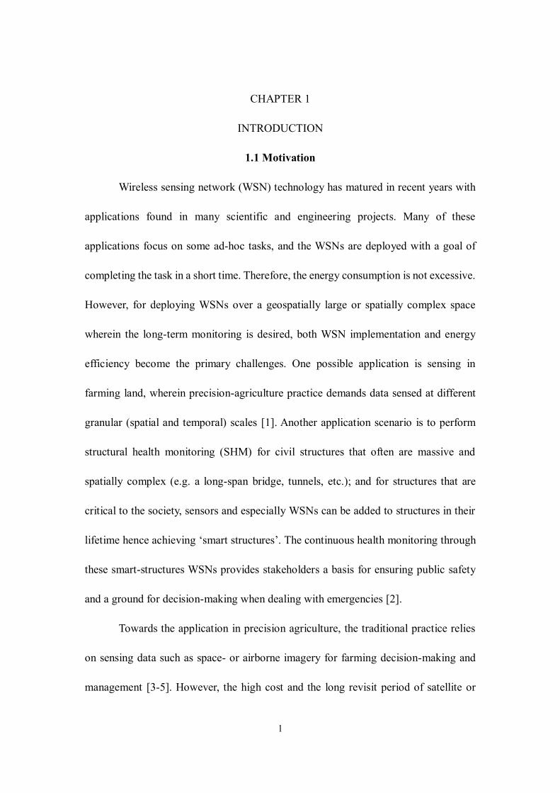
1.1 Motivation
Wireless sensing network (WSN) technology has matured in recent years with
applications found in many scientific and engineering projects. Many of these
applications focus on some ad-hoc tasks, and the WSNs are deployed with a goal of
completing the task in a short time. Therefore, the energy consumption is not excessive.
However, for deploying WSNs over a geospatially large or spatially complex space
wherein the long-term monitoring is desired, both WSN implementation and energy
efficiency become the primary challenges. One possible application is sensing in
farming land, wherein precision-agriculture practice demands data sensed at different
granular (spatial and temporal) scales [1]. Another application scenario is to perform
structural health monitoring (SHM) for civil structures that often are massive and
spatially complex (e.g. a long-span bridge, tunnels, etc.); and for structures that are
critical to the society, sensors and especially WSNs can be added to structures in their
lifetime hence achieving ‘smart structures’. The continuous health monitoring through
these smart-structures WSNs provides stakeholders a basis for ensuring public safety
and a ground for decision-making when dealing with emergencies [2].
Towards the application in precision agriculture, the traditional practice relies
on sensing data such as space- or airborne imagery for farming decision-making and
management [3-5]. However, the high cost and the long revisit period of satellite or
2
aerial imagery may prevent applying precision agriculture solutions at any location and
any time around the world. Images taken by low-altitude remote sensing platforms,
such as unmanned aerial vehicles (UAVs or commonly called drones), give the
alternative solution in the emerging precision agriculture practice [6-8]. In addition,
since microelectromechanical systems (MEMS) technology and particularly the
emerging Internet of Things (IoT) sensing technology, have been rapidly improved in
recent decades, many researchers have proposed and implemented different ground-
based wireless sensors solutions for facilitating precision agriculture [9-13].
In the arena of SHM, the traditional utility has been the use of wired or wireless
sensors to obtain in the real-time the response of structures due to environmental or
hazards-induced vibrations [14-17]. Upon the archival of response data, most SHM
technologies then employ signal processing and system identification methods with a
goal of characterizing the intrinsic states of the structures. In reality, however, for
structures with slight to moderate damage, such as local cracking and corrosion, visual
or remote sensing based inspection is the most efficient approach to date. In recent
years, as the penetration of UAV technology into many industrial sectors, small-UAVs
enabled remote sensing, which is low-cost and highly mobile, is being treated as an
emerging tool that expands the SHM technology inventory [18-20]. In recent years,
many researchers envision the deployment of SHM to an urban scale for the grand goal
of community resilience, for which all critical civil structures and infrastructure systems
need to be monitored in coping with life-cycle maintenance or abrupt emergencies [21].
This further corroborates the necessity of combining WSNs and remote sensing
3
technologies.
Reflecting on the trends in precision agriculture and SHM, we have proposed
and developed a prototype of realizing a wireless aerial-imaging and ground-sensing
network; or in short, aerial-ground wireless sensing network (AG-WSN). This
prototype has the capability of capturing both high-resolution imagery and real-time
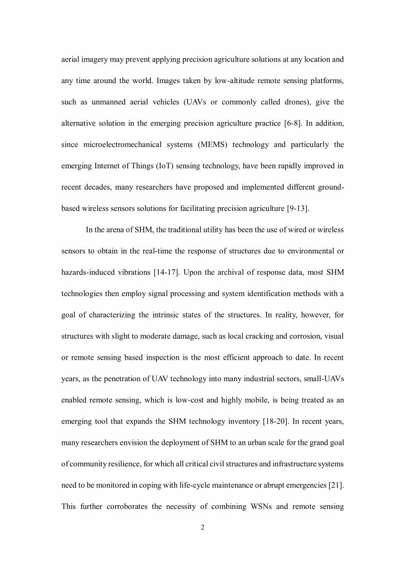
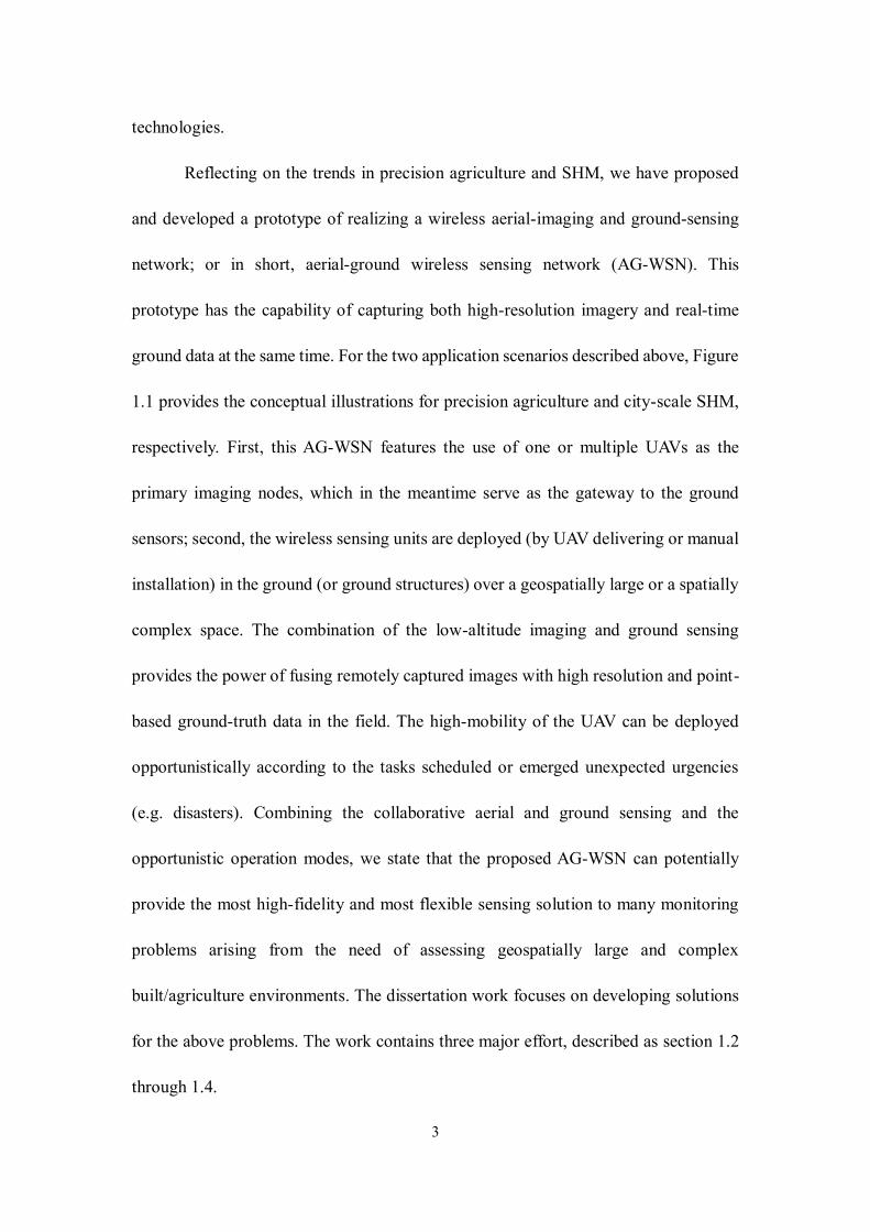
ground data at the same time. For the two application scenarios described above, Figure
1.1 provides the conceptual illustrations for precision agriculture and city-scale SHM,
respectively. First, this AG-WSN features the use of one or multiple UAVs as the
primary imaging nodes, which in the meantime serve as the gateway to the ground
sensors; second, the wireless sensing units are deployed (by UAV delivering or manual
installation) in the ground (or ground structures) over a geospatially large or a spatially
complex space. The combination of the low-altitude imaging and ground sensing
provides the power of fusing remotely captured images with high resolution and point-
based ground-truth data in the field. The high-mobility of the UAV can be deployed
opportunistically according to the tasks scheduled or emerged unexpected urgencies
(e.g. disasters). Combining the collaborative aerial and ground sensing and the
opportunistic operation modes, we state that the proposed AG-WSN can potentially
provide the most high-fidelity and most flexible sensing solution to many monitoring
problems arising from the need of assessing geospatially large and complex
built/agriculture environments. The dissertation work focuses on developing solutions
for the above problems. The work contains three major effort, described as section 1.2
through 1.4.
4
(a)
(b)
Figure 1.1 Conceptual illustrations of the proposed aerial-ground wireless sensing
network (AG-WSN) for field monitoring: (a) largely 2-D terrain field in an agriculture
setting; and (b) complex 3D field in an urban setting.
1.2 Energy Optimization for Sensor Network
Although solar power or other intermittent energy-supply techniques exist,
battery power is continued being considered as the most reliable source for powering
sensors and robots. By implementing the commonly adopted duty-cycle method,
wireless sensor nodes could be pre-programmed to wake up and communicate with the
gateway, then go back to sleep after communicating. This approach for extending
battery life has been treated as a default function in many commercial wireless sensors.
Researchers also try to optimize the power management to further extend the battery
life of WSNs [22-25]. However, one key problem that prevents us from realizing a long-
5
term aerial-ground sensing is the opportunistic nature of deploying the UAV (gateway)
and the sensor notes. In an AG-WSN, the gateway (as a payload of the UAV) is
deployed to approach to the ground sensors on a non-scheduled basis or randomly upon
the abrupt events. This further implies that the ground sensors do not have ‘knowledge’
or are not programmable to realize the duty-cycle sensing. If the ground sensors are
turned on at least including the microcontroller / communication units (whereas the
sensing units may be on or off according to the duty cycles), the battery of the sensor
nodes may be drained quickly.
One straightforward approach to such energy inefficiency issue is to wake up
ground sensor nodes when the UAV is deployed as needed to approach to the sensors
without any preprogramming. In the dissertation, we first propose to use a radio-
frequency (RF) based out-of-band wake-up mechanism. Then comparative studies are
conducted to investigate their energy saving performance against two other wake-up
mechanisms. Using a traditional star-like sensor network, the analytical and
experimental studies show solid evidence that the RF-based wake-up mechanism
outperforms traditional duty cycle solution and infrared-based wake-up solution on
energy consumption.
1.3 Wireless Interference in AG-WSN
It is noted that modern UAVs are often equipped with communication modules
and can further carry sensing and routing payloads. This provides the technical
feasibility of incorporating UAVs into a WSN that networks with regular ground-based
6
sensors. On the other hand, the potential of integration UAVs into a WSN is also
corroborated by a critical challenge in deploying practical WSNs in challenging
environments. For instance, since sensors are usually battery-powered, field sensors are
often deactivated and in the ‘sleep’ mode. Moreover, in a harsh environment or
circumstance such as in disaster scenes where cellular networks are crippled, data may
become ultimately inaccessible even if a local WSN survives. These challenges can be
overcome by taking advantage of the aerial mobility of the UAVs. One solution is to
use a UAV to fly to the overhead of the ground WSN, and activate the sensors in an as-
needed basis hence achieving maximum energy efficiency [26]. To access data from a
ground WSN, the UAV may serve as a gateway to receive data from the ground sensors.
It is noted that the concept of integrating UAVs into a WSN or realizing dynamic relay
of communication has been similarly proposed by different researchers [27, 28].
However, no physical prototype or applications of such networks to civil infrastructure
monitoring is found to date.
Recognizing the potential promise of integrating UAV-based imaging and
ground-based WSN in improving the efficiency of collecting civil structures, in our
AG-WSN, the UAV is adapted to achieve two immediate roles – as an imaging sensor
providing overhead imagery and as a gateway (or data sink) that commands and
receives data from the ground sensors. In an earlier effort of the my work [29], the
concept of aerial-imaging and ground-sensing was proposed for use in the situation of
disaster response in a geospatially wide area. In the dissertation, this concept is
borrowed towards structural monitoring at a geospatial scale as well, wherein the health
7
and conditions of a single large-scale structure or clustered structures (e.g. in a wide
area such as a city block) are the concern. In recent years, it is noted that small UAVs
are further investigated for the use in an interior or GPS-denied environment with the
assistance of machine-vision based navigation [30, 31]. This implies that the proposed
AG-WSN may be further extended into use in these challenging environments.
Given such promise and towards deploying the proposed AG-WSN, however,
one practical issue that remains not fully resolved is the interference between the UAV’s
and the WSN’s operating frequencies. In practice, most UAVs use 2.4 GHz radio for
flight control and 2.4 GHz Wi-Fi (802.11 g/n/ac) for imagery data feeds. For low-power
sensing, ground-based WSNs often use the ZigBee (802.15.4) protocol, which may run
at 2.4 GHz as well. In the dissertation, an AG-WSN prototype using commercial
components is developed, and then the interference issue is experimentally studied.
1.4 UAV Path Planning in AG-WSN
The most traditional and reliable way for wireless sensing network (WSN)
method to collect sensing data is using a stationary gateway with multi-hop routing
[32]. In some conditions, however, it is not possible nor efficient to using such topology
due to the environment and energy restriction. The alternative method is using mobile
robotic as the gateway to collect data from the sensor nodes either in multi-hop routing
[33, 34], or star topology [35-37]. Unmanned aerial vehicle (UAV) is the perfect mobile
gateway for WSN thanks to its high mobility. The UAV will visit all the n sensor nodes
in the field once and only once in one trip to gather the sensing data through wireless
8
communication. The communication range between the UAV and sensor nodes is
limited by many factors like power, obstacles and antenna directions. This require the
UAV get close within the area Qi of each sensor node i. The UAV then will hover at
each point qi ∈ Qi of node i = 1,2…n for data collecting. limited UAV battery life
requires the UAV reaching out all the sensor nodes on the ground with the shortest path
to save energy.
This path planning for the UAV falls into category of Travelling Salesman
Problem with Neighborhood (TSPN), which was introduced by [38]. Early researchers
use small fixed wings to retrieve data [39]. Due to the nature of fixed wings, Dubins
Travelling Salesman Problem with Neighborhood seems fit this situation well and has
been studied for a while [40-42]. The downsides of these fixed-wing UAVs are: a) They
need a small airstrip to take off. b) They cannot hover above the sensor nodes, thus
collecting data require them to flying around which makes wireless communication
more difficult. Fortunately, with the development of new technology in Multi-Rotor
UAV, the above two problems can be solved. Therefore, the Multi-rotor UAV is the
perfect mobile gateway for WSN.
Traditional TSPN optimization aims to provide the shortest Euclidean distance
solution to visit all the neighborhood, since shorter path equals less time and energy
consumed by the salesman (which is UAV in WSN application). The research focus is
the energy optimization for UAV in the TSPN problem, since the UAV will stay
hovering during the communication with sensor node, and the energy consumption to
maintain hovering is almost identical to moving around [43], therefore, the energy
9
consumed during this hovering time must be taken into consideration when optimizing
the path. Thus, the shortest Euclidean path does not necessarily mean the lowest energy
consumption for the UAV. Traditional TSPN problem is already NP-hard, in practical,
the energy of the UAV system is consumed by multiple sources like motors, on board
computing units and wireless communication module, which makes the problem even
harder to solve. To simplify the problem, we focus on the major energy consumption
activity of the UAV, moving and hovering. In this dissertation, we modify existing
TSPN solution and use mixed-integer non-linear programming method to minimize the
total energy consumption of the UAV, by considering both energy consumed during
Euclidean distance traveling, and energy consumed when UAV is hovering for wireless
communication.
10
CHAPTER 2
DEVELOPMENT OF RADIO-FREQUENCY SENSOR WAKE-UP THROUGH
UAV AS AN AERIAL GATEWAY
2.1 Introduction
With advances in autonomous navigation, positioning, and in general robotics
technologies, small to miniature-sized unmanned aerial vehicles (UAVs; or colloquially
called drones) are witnessing their ever-increasing use in engineering practice, due to a
simple fact that they are much low-cost, agile and effective, particularly for geospatial
remote sensing platform when compared with traditional space- or airborne remote
sensing [44]. Today’s UAVs have well adopted the latest GPS technology; and many
small UAVs, especially the multi-motor ones can fly following the predetermined GPS
waypoints. Some advanced drones have been equipped with lost-cost radar or vision
sensors acquiring a minimum level of flying beyond (visual) line-of-sight (BVLOS or
BLOS) due to its sense-and-avoid capability [45-47]. This potentially would further
render small UAVs an attractive remote sensing platform for a great deal of different
applications.
On the other hand, wireless sensing network (WSN) technology has matured in
recent years with applications found in many scientific and engineering projects. Many
of WSN applications focus on ad-hoc tasks, and the local (contact-based usually
ground-based) sensors are deployed with a goal of completing the task in a short time.
Therefore, the energy consumption is not excessive. However, for deploying WSNs
over a geospatially large or spatially complex space wherein the long-term monitoring
11
is desired, both WSN implementation and energy efficiency become the primary
challenges. One possible application is sensing in farming land, wherein precision-
agriculture practice demands data sensed at different granular (spatial and temporal)
scales [1]. Another application scenario is to perform structural health monitoring
(SHM) for civil structures and life-line infrastructure systems that often are massive
and spatially complex (e.g. urban buildings, long-span bridge, and power transmission
lines/towers, etc.). For structures that are critical to the society, sensors and especially
WSNs can be installed for these structures in their lifetime hence achieving ‘smart
structures’. The continuous health monitoring through these WSNs provides
stakeholders a basis for ensuring public safety and a ground for decision-making when
dealing with unexpected damage or losses [2].
Still taking the two arenas of precision agriculture and structural health
monitoring as the application setting (Figure 1.1), it is asserted that in both situations,
the necessity of combining UAV-based remote sensing and WSNs is straightforward.
In the setting of precision agriculture, the traditional practice relies on sensing data such
as space- or airborne imagery for farming decision-making and management [3-5].
However, the high cost and the long revisit period of satellite or aerial imagery may
prevent applying precision agriculture solutions at any location and any time around
the world. Images taken by low-altitude UAVs give the alternative solution in the
emerging precision agriculture practice [6-8]. In addition, since
microelectromechanical systems (MEMS) technology and particularly the emerging
Internet of Things (IoT) sensing technology, have been rapidly improved in recent
12
decades, many researchers have proposed and implemented different ground-based
wireless sensors solutions for facilitating precision agriculture [9-13]. Towards data
fusions and more intelligent and tactic operation of these sensing modalities, integration
of UAVs and ground-based WSNs becomes a rational choice.
In the arena of SHM, the traditional utility has been the use of wired or wireless
sensors to obtain in the real-time the response of structures due to environmental or
hazards-induced vibrations [14-17]. In reality, however, for structures with slight to
moderate damage, such as local cracking and corrosion, visual or remote sensing based
inspection is the most efficient approach to date. In recent years, as the penetration of
UAV technology into many industrial sectors, small-UAVs enabled remote sensing,
which is low-cost and highly mobile, is being treated as an emerging tool that expands
the SHM technology inventory [18-20]. This further corroborates the necessity of
combining WSNs and UAV-based remote sensing technologies.
Reflecting on the trends in precision agriculture, SHM and other field
applications for critical missions, we have proposed and developed a prototype of
realizing a wireless aerial-imaging and ground-sensing network; or in short, aerial-
ground wireless sensing network (AG-WSN) [48]. First, this AG-WSN features the use
of one or multiple UAVs as the primary imaging nodes, which in the meantime serve
as the gateway to the ground sensors; second, the wireless sensing units are deployed
(by UAV delivering or manual installation) in the ground (or ground structures) over a
geospatially large or a spatially complex space. The combination of the low-altitude
imaging and ground sensing provides the power of fusing remotely captured images
13
with high resolution and point-based ground-truth data in the field. The high-mobility
of the UAV can be deployed opportunistically according to the tasks scheduled or
emerged unexpected urgencies (e.g. disasters). Combining the collaborative aerial and
ground sensing and the opportunistic operation mode (e.g. a ground node may be only
active when the UAV hovers above it and collects data from it), we state that the
proposed AG-WSN can potentially provide the most high-fidelity and most flexible
sensing solution to many monitoring problems arising from the need of assessing
geospatially large and complex built/agriculture environments.
In this paper, first, addressing the opportunistic nature of the AG-WSN, we first
review the related UAV-WSN integration efforts and propose a conceptual operation
design, which further motivates the proposition of sensor activation for network energy
efficiency. Centering around sensor activation, we propose to develop a sensor wake-
up solution, and the related work is provided that shows the benefits and drawbacks of
different wake-up design and the rationale for choosing an active RF mechanism.
Subsequently, a general out-band wake-up mechanism is developed and demonstrated.
For a comparative purpose, the infrared wake-up prototype is implemented too. We
further conduct a comprehensive study of the energy consumption on how much energy
can be saved, followed by the conclusions and remarks of this paper.
2.2 Opportunistic Sensing, and Research Needs
To our best knowledge, there were only a few efforts that attempted to integrate
UAVs with wireless sensor networks. In [27], UAVs are considered as mobile sinks for
ground sensor data dissemination. This approach intends to optimize the route from a
14
given sensor node on the ground to a few mobile sinks that move in the area. [28]
presents a different approach that keeps the sensor network continually connected. It
uses multiple UAVs to establish a reliable relay network to guarantee the delivery of
data produced by the wireless network nodes on the ground to the users. Given these
few simulation-based and conceptual efforts, much fewer efforts are found to physically
realized UAV-based sensing network system. In a recent effort, the authors developed
a WSN using a fixed-wing UAV as the aerial gateway for marine data collection [49].
In our recent effort, we further investigated the interference between the WiFi-based
video transmission link and the ZigBee-based ground-data transmission links [48].
The use of flying single or multiple UAVs either as a mobile sensor node or a
data sink triggers the effort of optimizing network efficiency between sensors and sinks,
among which energy cost is an inevitable constraint considering that both the UAVs
and ground sensors are usually battery-powered to this date. Opportunistic Network is
the emerging technology that solve such optimization problem. In [50], it proposes
protocols to better exploit durations of high-quality channels condition. Based on that,
[51] proposed routing protocols that increase the throughput of large unicast transfers
in multi-hop wireless network. There are also research efforts on optimizing resource
and performance in wireless sensor networks (e.g. [52]). It considers a different
scenario where the paths from message sources and their destinations do not always
exist. Then the authors analyzed protocols that alleviate the problem of chronically
disconnected paths by having a node storing the packet, carrying it until meeting
another relay node, and forwarding the packet to the other relay node. In a more recent
15
effort, researchers also developed middleware that implemented the opportunistic
network into mobile social networks, called CAMEO [53]. It is stated that these
optimization schemes mostly focus on designing improved communication protocols
by assuming that either the UAVs or the sensors are not constrained by the battery-
based power. It is noted that in general opportunistic networking (without using a UAV
as a gateway node), different protocols are proposed, including the flooding protocol
and the history-based protocol (e.g. [54, 55]).
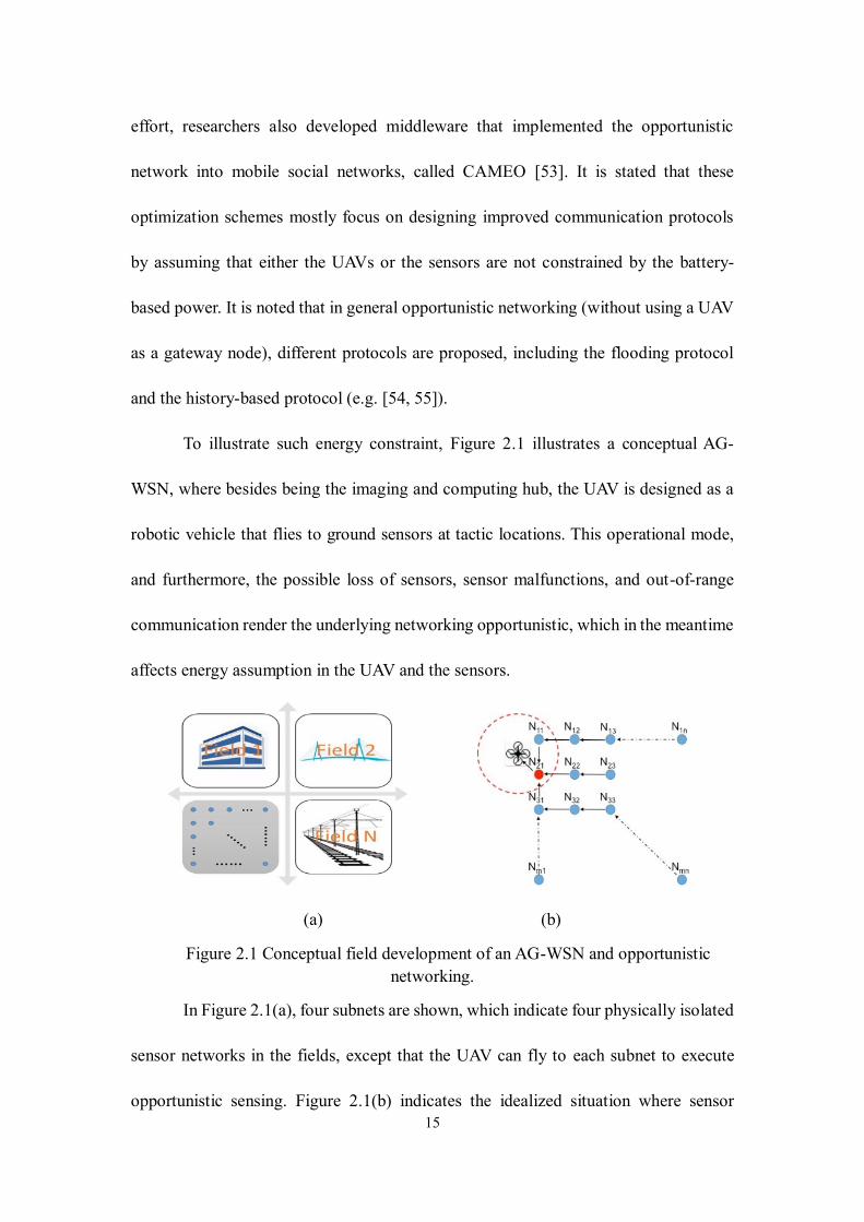
To illustrate such energy constraint, Figure 2.1 illustrates a conceptual AG-
WSN, where besides being the imaging and computing hub, the UAV is designed as a
robotic vehicle that flies to ground sensors at tactic locations. This operational mode,
and furthermore, the possible loss of sensors, sensor malfunctions, and out-of-range
communication render the underlying networking opportunistic, which in the meantime
affects energy assumption in the UAV and the sensors.
(a) (b)
Figure 2.1 Conceptual field development of an AG-WSN and opportunistic
networking.
In Figure 2.1(a), four subnets are shown, which indicate four physically isolated
sensor networks in the fields, except that the UAV can fly to each subnet to execute
opportunistic sensing. Figure 2.1(b) indicates the idealized situation where sensor
16
failure (or other malfunctions) and energy consumption are not needed to consider.
Hence, assuming each node Nij can communicate with its neighboring nodes Ni±1,j±1
through wireless connection, when the UAV fly into this sub-network, some of the
nodes are in communication range to the UAV, while some are not. The UAV will pick
one of the nodes in the range as a relay node, and collect data from any other node in
this subnet. Then the existing optimal communication protocols can be used.
When the energy consumption of either the UAV or sensor networks are
considered, optimization in the physical layer (rather than in the communication
protocols) need to be addressed. Two obvious venues exist: (1) through spatial path-
energy optimization, the UAV finds the optimal flying path through the geospatially
deployed ground sensors, for which it is being tackled in Chapter 4 of this dissertation;
and (2) as being concentrated in this paper, through a sensor activation approach, as
such the sensors are only active when the UAV is in its neighborhood.
2.3 Sensor Activation and Related Work
Although solar power or other intermittent energy-supply techniques exist,
battery power is continued being considered as the most reliable source for powering
sensors and robots. By implementing the commonly adopted duty-cycle method,
wireless sensor nodes could be pre-programmed to wake up and communicate with the
gateway, then go back to sleep after communicating. This approach for extending
battery life has been treated as a default function in many commercial wireless sensors.
Researchers also try to optimize the power management to further extend the battery
life of WSNs [22-25]. However, one key problem that prevents us from realizing a long-
17
term aerial-ground sensing is the opportunistic nature of deploying the UAV (gateway)
and the sensor notes. In an AG-WSN, the gateway (as a payload of the UAV) is
deployed to approach to the ground sensors on a non-scheduled basis or randomly upon
the abrupt events. This further implies that the ground sensors do not have ‘knowledge’
or are not programmable to realize the duty-cycle sensing. If the ground sensors are
turned on at least including the microcontroller / communication units (whereas the
sensing units may be on or off according to the duty cycles), the battery of the sensor
nodes may be drained quickly.
One straightforward approach to such energy inefficiency issue is to wake up
ground sensor nodes when the UAV is deployed as needed to approach to the sensors
without any preprogramming. In this paper, we first propose to use a radio-frequency
(RF) based out-of-band wake-up mechanism. Then comparative studies are conducted
to investigate their energy saving performance against two other wake-up mechanisms.
Using a traditional star-like sensor network, the analytical and experimental studies
show solid evidence that the RF-based wake-up mechanism outperforms other two
solutions on energy consumption.
Earlier efforts reveal that data transmission in a WSN is generally very
expensive in terms of energy consumption, whereas data collection (or the sensing
itself) consumes significantly less [56]. For this reason, various methods are developed
to extend the life of battery-powered WSNs by reducing the power consumption of the
wireless modules. A significant number of efforts were found that focused on
developing lower-level network protocols by adopting duty-cycle based solutions [57-
18
59]. These studies aimed to optimize the network protocols, specifically through
reducing the energy consumption during the idle or the listening time of the wireless
modules. For example, the authors in [60] proposed an adaptive Medium Access
Control (MAC) protocol, which introduced a flexible duty-cycle method and claimed
to reduce 96% of energy use compared with traditional protocols. However, the core
concern for these duty-cycle solutions is that the wireless modules do not know when
the data transmission is coming or required, the node must listen periodically to limit
data latency, thus the duty-cycle ratio cannot go arbitrarily low [61]. Also, duty-cycle
methods may have problems with delay and synchronism; and hence the protocol is
relatively complicated. As such, the waking-up mechanisms as an answer to this
concern have been extensively studied.
Different sensor activation methods were proposed to date. Essentially, such
activation approach features a waking-up mechanism for activating sensing modules in
an as-needed (or on-demand) basis. There are two methods when considering wake-up
mechanisms for use in wireless networks, which are in-band and out-band. If an in-
band method is used, a special value is transmitted through the data channel to send out
the wake-up signal. By contrast, a separate channel is needed to realize such waking-
up mechanism in an out-band method. Using the in-band methods can reduce the
complexity and cost of the implementation. A recent study of the in-band wake-up
method [62] claimed that by using both game theory and reinforcement learning
techniques, it achieved very effective sleep/wake-up scheduling. However, it keeps the
wireless communication channel busy and may require more energy consumption.
19
From the energy-efficiency perspective, the out-band approach suits more for the
proposed concept that emphasizes opportunistic aerial-ground sensing.
There are many studies that employ the out-band wake-up mechanism [63]. In
this paper, they are categorized into two groups according to their communication
medium: (1) non-RF based and (2) RF-based. In a non-RF based mechanism,
researchers proposed wake-up methods using infrared (IR), optical and acoustic signals.
The authors in [64] developed an IR LED based wake-up mechanism, in which the
receiver is a photo-detector receiving IR signal and then generate an interrupt. The
authors stated that the IR design only consumed 12 μW while listening. It is noted that
the obvious drawback of this prototype is its circuit’s sensitivity to external light and
vulnerability to ambient noise. In [65], the authors presented a home-energy
management system using infrared signal-based control over a Zigbee network. In this
system, an infrared receiver is attached to the Zigbee gateway. The Zigbee gateway is
responsible for communicating with other home appliances, whereas the infrared
remote control is the out-band wake-up channel used to wake up the Zigbee network.
Unfortunately, this paper did not mention the power consumption of the IR receiver. To
our understanding, this type of IR receiver in the paper is commercially available and
similar to the one used in our experiment as shown in this paper, which has better
resistance to noise at a cost of much higher power consumption and may require up to
45 mW according to our experiment.
Optical communication is another non-RF option for the secondary wake-up
channel. Both [66, 67] used free-space optical (FSO) communication as the transceiver.
20
The receiver at idle-listening consumes 317 μW and 695 pW. However, the transceiver
and receiver both need to be placed line-of-sight (LOS) and the data rate is slow. It is
impractical for use in a UAV that mostly time does not stay in position to accurately
face the transmitter. Thus, this option is not suitable for our application. The AG-WSN
scenario may also limit the use of acoustic as wake-up methods [68, 69] due to the noise
produced by the UAV blades. Ultrasonic, as stated in [70, 71], may avoid the noise
made by the UAV. It uses a piezoelectric transducer that converts the mechanical energy
into electrical energy for generating wake-up interrupts. However, most ultrasonic
communication or ranging efforts to date are mostly applied to indoor (short-range) or
LOS scenarios [72, 73] .
Compare with the non-RF based wake-up mechanisms reviewed above, first of
all, the RF-based communication has the advantages of not requiring LOS, better noise
and interference tolerance, higher data rate, and is more cost-effective. The research
endeavors on the RF-based wake-up mechanism can be divided into two designs:
passive wake-up and active wake-up, both of which have been well studied in the
laboratory environment. In a passive design, the RF receiver harvests energy from the
transmitter to power itself thus requires no power supply [74-76]. In [77], it simulated a
passive RF wake-up receiver, in which the authors indicated that comparing with the
existing duty-cycle method, their RF wake-up can significantly enhance energy
efficiency by up to 70%. There are also simulation endeavors on both passive and active
RF wake-up circuits, such as [78, 79]; the authors of these efforts later implemented the
passive RF circuit into a sensor network with a multi-hop capability [80]. However,
21
among these passive RF-based methods, information on the communication range
between the transceivers was not found. In addition, it was reported that the energy of
the receiver harvests may decrease with increasing distance between the receiver and
the transmitter. The authors in [81, 82] showed that the hardware setup can only reach a
maximum distance of 4 meters for a successful wake-up. Considering the AG-WSN
scenario proposed in this work, it is stated that the passive RF-based wake-up is not
suited.
Regarding the active RF wake-up design, as mentioned in [61], there are 13
active RF-based wake-up methods using discrete components, whereas there are 29
methods using CMOS technology. The most significant parameters relevant to these
designs and prototypes for the interest of the proposed AG-WSN configuration are
power consumption, range, address decoding capability, wake-up latency, and their
balancing. For example, the author in [83] configured the wake-up receiver using
discrete components and claimed to achieve 120 meters of communication range.
However, the receiver consumes 1620 μW at the state of idle-listening, which is too
high for the battery-powered nodes. There is a low-power design in [84], which only
consumes 52 μW; unfortunately, the authors did not provide a range test. A
favorable design was presented in [85] recently. It achieved a communication range of
50 meters at idle-listening with a power consumption of 1.2 μW. Unfortunately, at the
time of our experiment, there was no market-ready product or porotype based on this
design.
22
In this paper, it is stated that the use of off-the-shelf components is stressed in
our prototyping and experimental validation with the goal of putting the proposed AG-
WSN into practice rapidly. As many researchers similarly used, the AS393X wake-up
receiver has been used in many efforts and designs [86-90]. Among these researches,
the author in [89] used AS3933, which is the same chip in our experiment, to prototype
the receiver circuit to have an 87-meter communication range, at the cost of more than
5000 μW power consumption when decoding the wake-up signal. Also, in a recent
paper, the authors compared the RF wake-up mechanism and the low-power listening
techniques [91] and concluded similarly what we achieve in our energy evaluation
results in this paper. However, the authors of this paper did not measure the delay caused
by the RF wake-up transmission, and their power consumption measurement was not
based on battery but a constant power supply, hence lacking a realistic configuration.
2.4 Proposed Energy Efficient Sensing Network
2.4.1 Topology and Implementation
In our aerial-ground approach, the UAV is the wireless network gateway, which
is responsible for communicating with each individual sensor node that is deployed in
the field. Although there are many wireless protocols that can be configured for these
sensors nodes, we choose XBee (a modified Zigbee wireless protocol) wireless module
for constructing the network, since its power consumption is relatively low. The XBee
23
protocol allows three types of network topologies, which include: star, mesh, and
cluster-tree. Although mesh and cluster-tree networks have a very flexible network
structure, they both require some sensor nodes in the network for relaying data to the
gateway, which means that these relay nodes have to be either always active or being
duty-cycle active, further consuming a significant amount of power. Alternatively, the
star topology does not require any node to relay information, and they can be kept in
sleep modes for most of the time. When using the star topology, the UAV will be the
XBee coordinator (gateway) for collecting data from multiple ground nodes in the
communication range. More importantly, it is the high-mobility UAV that will wake up
multiple ground sensor nodes from the sleeping state on the demand of the UAV, which
can fly to the overhead of individual or a group of sensors to perform sensor activation
and data collection. Therefore, the star topology is considered the most appropriate one
for the proposed aerial-ground network.
One concern is that using UAV as a flying gateway may consume more energy
per a UAV flight than what could potentially be saved in our wake-up mechanism. The
fact is that in most cases, the batteries in sensor nodes are hard to replace due to a variety
of reasons, such as the position of the node is difficult to reach, or battery is sealed in a
box and buried in soil or structures to prevent harsh weather conditions. The key
concept of our approach is to reduce the consumption of the sensor-node batteries in
the field as much as possible to sustain service time as long as possible. For the power
consumption, we state that in reality multiple identical UAVs with multiple high-
capacity battery backups can be used to perform their functions of remote sensing and
24
being the network gateway.
Last, for implementing the sensing nodes, we use Libelium’s Waspmote® as our
ground sensing nodes [92]. The Waspmote sensing node contains a low-power MCU,
embedded sensors, and optional wireless module slots. It consumes a quite small
amount of energy when its sleeping mode is selected.
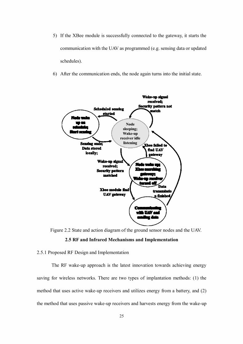
2.4.2 General Active Out-band Wake-up Mechanism
As reviewed earlier, active out-band wake-up mechanism is chosen for the
proposed AG-WSN. To understand this mechanism, Figure 2.2 summarizes the state
and action diagram for the wake-up mechanism and the sensor-node operation. A
description is given as follows:
1) When the sensor node is deployed in the field, it is pre-programmed with a
duty-cycle sensing schedule, then it is turned into sleep mode, which we
call the initial state. Only the wake-up receiver is listening, in our example,
which is either an infrared or RF wake-up receiver.
2) If a wake-up signal is received by the sensor node, it will check whether the
signal matches the pre-stored pattern. If not, the node ignores the signal and
changes back to the initial state.
3) If the wake-up signal matches the stored pattern, the node wakes up, starts
the XBee module, and turns off the wake-up receiver. Then the XBee begins
scanning the gateway on the UAV.
4) If the XBee module fails to find the gateway in a couple of tries, the node
shuts down the XBee module and turns back into the initial state.
25
5) If the XBee module is successfully connected to the gateway, it starts the
communication with the UAV as programmed (e.g. sensing data or updated
schedules).
6) After the communication ends, the node again turns into the initial state.
Figure 2.2 State and action diagram of the ground sensor nodes and the UAV.
2.5 RF and Infrared Mechanisms and Implementation
2.5.1 Proposed RF Design and Implementation
The RF wake-up approach is the latest innovation towards achieving energy
saving for wireless networks. There are two types of implantation methods: (1) the
method that uses active wake-up receivers and utilizes energy from a battery, and (2)
the method that uses passive wake-up receivers and harvests energy from the wake-up
26
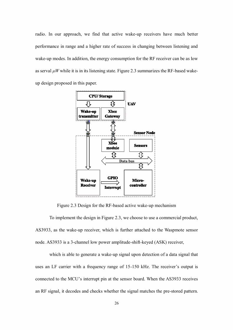
radio. In our approach, we find that active wake-up receivers have much better
performance in range and a higher rate of success in changing between listening and
wake-up modes. In addition, the energy consumption for the RF receiver can be as low
as serval µW while it is in its listening state. Figure 2.3 summarizes the RF-based wake-
up design proposed in this paper.
Figure 2.3 Design for the RF-based active wake-up mechanism
To implement the design in Figure 2.3, we choose to use a commercial product,
AS3933, as the wake-up receiver, which is further attached to the Waspmote sensor
node. AS3933 is a 3-channel low power amplitude-shift-keyed (ASK) receiver,
which is able to generate a wake-up signal upon detection of a data signal that
uses an LF carrier with a frequency range of 15-150 kHz. The receiver’s output is
connected to the MCU’s interrupt pin at the sensor board. When the AS3933 receives
an RF signal, it decodes and checks whether the signal matches the pre-stored pattern.
27
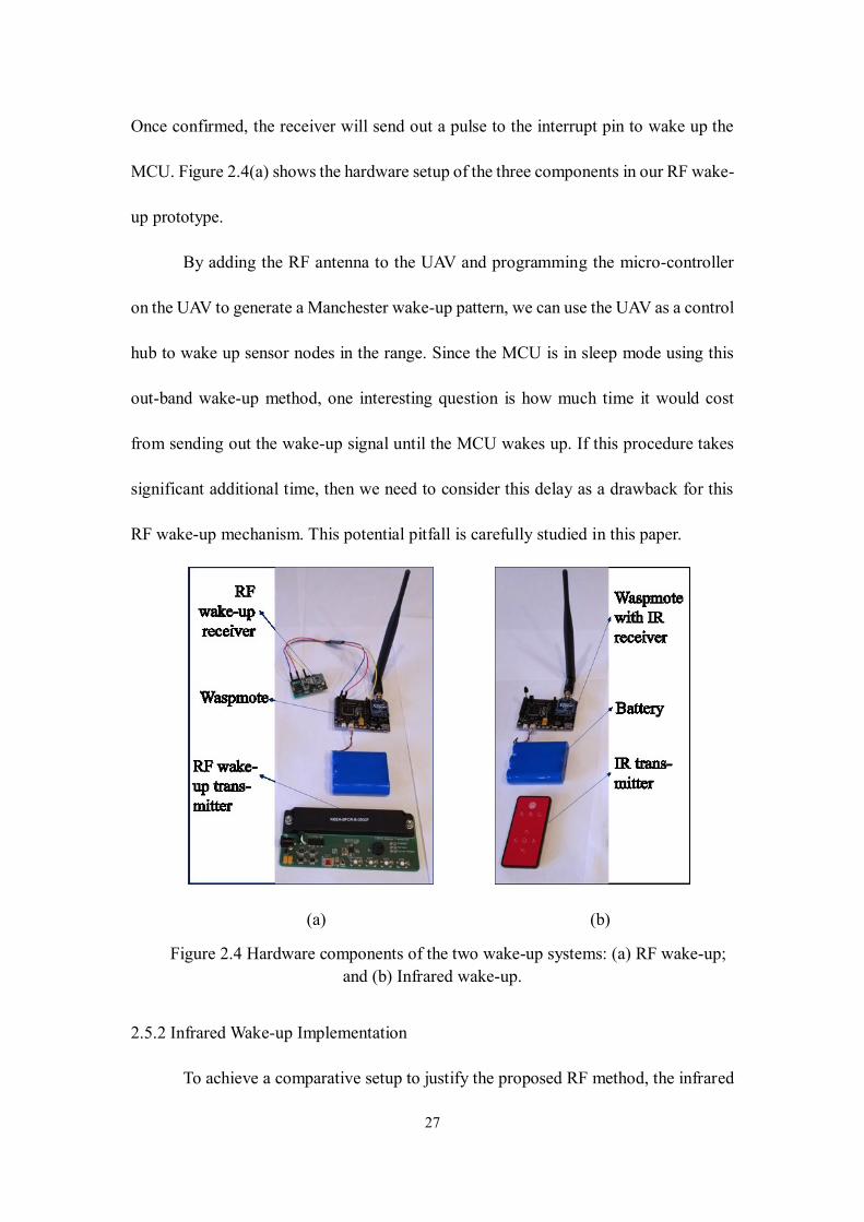
Once confirmed, the receiver will send out a pulse to the interrupt pin to wake up the
MCU. Figure 2.4(a) shows the hardware setup of the three components in our RF wake-
up prototype.
By adding the RF antenna to the UAV and programming the micro-controller
on the UAV to generate a Manchester wake-up pattern, we can use the UAV as a control
hub to wake up sensor nodes in the range. Since the MCU is in sleep mode using this
out-band wake-up method, one interesting question is how much time it would cost
from sending out the wake-up signal until the MCU wakes up. If this procedure takes
significant additional time, then we need to consider this delay as a drawback for this
RF wake-up mechanism. This potential pitfall is carefully studied in this paper.
(a) (b)
Figure 2.4 Hardware components of the two wake-up systems: (a) RF wake-up;
and (b) Infrared wake-up.
2.5.2 Infrared Wake-up Implementation
To achieve a comparative setup to justify the proposed RF method, the infrared
28
wake-up mechanism is too implemented physically in this endeavor. Infrared is a
commonly used solution for simple wireless communication at short ranges [63]. There
are two basic components in an infrared wireless communication: emitter and receiver.
The emitter first transmits the coded data, generated by the micro-controller, to the
receiver. When the receiver reads the IR signal, it decodes the signal into digital data
and then passes the information to its following component, i.e., the sensor node. In our
implementation, we integrate a 950 nm-emitting IR LED onto our UAV, and a
TSOP38238 IR Receiver Module on the sensor board; Figure 2.4(b) shows these
modules. The emitter is connected to the UAV on board with an MCU’s PWM-capable
I/O pin, and the receiver is connected to the MCU regular digital I/O pin on the sensor
board.
To achieve the wake-up function, the emitter on the UAV will send out the wake-
up signal to the receiver, only when the signal matches the code that is stored in the
MCU (on the sensor board), the sensor board then turns on its sensors and XBee
communication module. In this setup, sensors and XBee module can be turned off until
the MCU receives the wake-up signal. However, it requires that the sensor board MCU
always stay on to check whether the infrared signal matches the specific pattern.
2.6 Experimentation and Results
In the following, we evaluate the wake-up range as well as the energy
consumption for both out-band methods (RF and IR), then compare the energy cost
with the traditional duty-cycle method, all based on the same hardware setup.
2.6.1 Physical Verification and Comparison
29
The RF wake-up, however, does not require a direct LOS. The receiver,
AS3933, has three wake-up channels, each connecting to an antenna. In our test, the
three antennas were set up perpendicularly. Any antenna received the correct pattern
may trigger the wake-up. We tested the wake-up range using the similar method; and
we found that to successfully wake up the sensor node, the maximum range was
affected by the power supply of the transmitter. In our test, we used a 125-KHz antenna
connected to the UAV’s MCU and external power supply. When the supply voltage for
the transmitter was set to 9 V, the maximum range was around 7 meters in an indoor
environment. A similar result in the outdoor test using the same receiver is found in
[86], which resulted in a 5-meter range using 12-V supply for the transmitter.
2.6.2 RF Wake-up Delay
Since it takes time for the MCU to wake up from sleeping, we expect that this
may cause a delay in the data gathering for the WSN. Other wake-up receiver designs
like the one reported in [93] claimed to have a latency of 214 milliseconds; while in
[85], the author achieved around 0.9 milliseconds. We want to compare our set up with
other wake-up design to make sure the latency value is in an acceptable range. To
evaluate this and to measure the time from the transmitter at sending a signal, to the
MCU at waking-up and returning to the normal routine, we set up a novel
photogrammetric test environment. In the RF wake-up setup, we have three different
components, which have been introduced in Figure 2.4(a), the wake-up transmitter, the
wake-up receiver, and the MCU. The measurement operates as follows:
1. When the transmitter sends out the wake-up signal, the LED on the
30
transmitter will flash, the moment at which is defined as t1.
2. When the receiver receives the signal and decodes it if the signal
matches the pre-stored key, then the LED on the receiver will flash, the
moment at which is t2.
3. When the receiver sends out the wake-up trigger to the MCU interrupt
pin, then the MCU wakes up and the LED on MCU board will flash (t3).
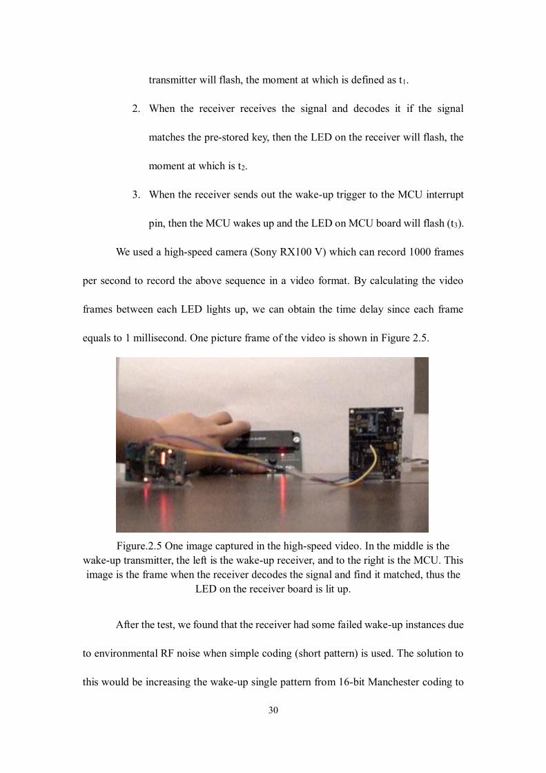
We used a high-speed camera (Sony RX100 V) which can record 1000 frames
per second to record the above sequence in a video format. By calculating the video
frames between each LED lights up, we can obtain the time delay since each frame
equals to 1 millisecond. One picture frame of the video is shown in Figure 2.5.
Figure.2.5 One image captured in the high-speed video. In the middle is the
wake-up transmitter, the left is the wake-up receiver, and to the right is the MCU. This
image is the frame when the receiver decodes the signal and find it matched, thus the
LED on the receiver board is lit up.
After the test, we found that the receiver had some failed wake-up instances due
to environmental RF noise when simple coding (short pattern) is used. The solution to
this would be increasing the wake-up single pattern from 16-bit Manchester coding to
31
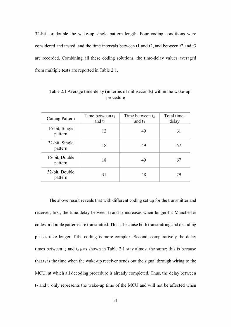
32-bit, or double the wake-up single pattern length. Four coding conditions were
considered and tested, and the time intervals between t1 and t2, and between t2 and t3
are recorded. Combining all these coding solutions, the time-delay values averaged
from multiple tests are reported in Table 2.1.
Table 2.1 Average time-delay (in terms of milliseconds) within the wake-up
procedure
Coding Pattern Time between t1
and t2
Time between t2
and t3
Total time-
delay
16-bit, Single
pattern 12 49 61
32-bit, Single
pattern 18 49 67
16-bit, Double
pattern 18 49 67
32-bit, Double
pattern 31 48 79
The above result reveals that with different coding set up for the transmitter and
receiver, first, the time delay between t1 and t2 increases when longer-bit Manchester
codes or double patterns are transmitted. This is because both transmitting and decoding
phases take longer if the coding is more complex. Second, comparatively the delay
times between t2 and t3 in as shown in Table 2.1 stay almost the same; this is because
that t2 is the time when the wake-up receiver sends out the signal through wiring to the
MCU, at which all decoding procedure is already completed. Thus, the delay between
t2 and t3 only represents the wake-up time of the MCU and will not be affected when
32
different coding patterns are used.
Regardless, through this experiment, since the total delay caused by using this
RF wake-up mechanism is less than 80 milliseconds (from sending out the wake-up
signal by the transmitter to the MCU’s wake-up), we can safely conclude that this
wireless wake-up mechanism will not affect the data communication between the
gateway and the sensor nodes in the field for most sensing applications, where the
sensors sense data packets at a time and transmit at a different time, then stay idle with
much longer duration. The study in [94] claimed to reduce the time between t1 and t2
roughly from 13 ms to about 2 ms using 16-bit and single pattern with the similar setup
in this paper. We thought this could potentially further reduce the latency introduced by
this out-band wake-up mechanism. Another study in [87] using the same chipset claims
the time between t2 and t3 to be 45.87 ms, which is similar to our experiment.
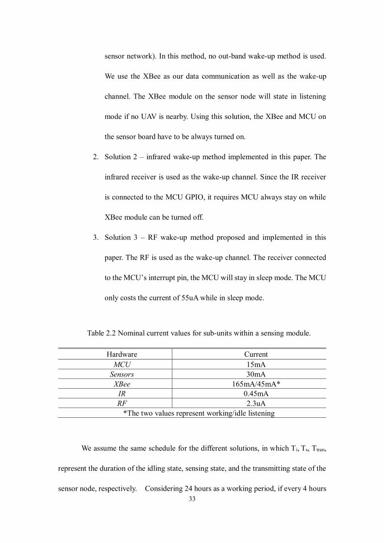
2.5.3 Energy Consumption Analysis and Verification
The energy consumption is one of the primary concerns of this paper. Our main
study focuses on the energy consumption in the sensor nodes that are potentially
deployed in the hard-accessible field. Specifically, we classify each sensor module
hardware into four sub-units represented by the primary device: the MCU, XBee
module, wake-up receiver, and the sensors. In Table 2.2, we list the typical current
consumption with a 3.3 V supply voltage for this hardware. We did the comparative
experiment on one default (duty-cycle) energy-saving mode and two wake-up
mechanisms as we explained earlier, and recorded the power consumption:
1. Solution 1 – the simple duty-cycle method (default in the Libelium
33
sensor network). In this method, no out-band wake-up method is used.
We use the XBee as our data communication as well as the wake-up
channel. The XBee module on the sensor node will state in listening
mode if no UAV is nearby. Using this solution, the XBee and MCU on
the sensor board have to be always turned on.
2. Solution 2 – infrared wake-up method implemented in this paper. The
infrared receiver is used as the wake-up channel. Since the IR receiver
is connected to the MCU GPIO, it requires MCU always stay on while
XBee module can be turned off.
3. Solution 3 – RF wake-up method proposed and implemented in this
paper. The RF is used as the wake-up channel. The receiver connected
to the MCU’s interrupt pin, the MCU will stay in sleep mode. The MCU
only costs the current of 55uA while in sleep mode.
Table 2.2 Nominal current values for sub-units within a sensing module.
Hardware Current
MCU 15mA
Sensors 30mA
XBee 165mA/45mA*
IR 0.45mA
RF 2.3uA
*The two values represent working/idle listening
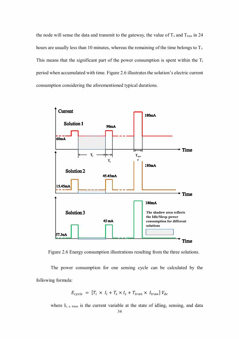
We assume the same schedule for the different solutions, in which Ti, Ts, Ttran,
represent the duration of the idling state, sensing state, and the transmitting state of the
sensor node, respectively. Considering 24 hours as a working period, if every 4 hours
34
the node will sense the data and transmit to the gateway, the value of Ts and Ttran in 24
hours are usually less than 10 minutes, whereas the remaining of the time belongs to Ti.
This means that the significant part of the power consumption is spent within the Ti
period when accumulated with time. Figure 2.6 illustrates the solution’s electric current
consumption considering the aforementioned typical durations.
Figure 2.6 Energy consumption illustrations resulting from the three solutions.
The power consumption for one sensing cycle can be calculated by the
following formula:
𝐸𝑐𝑦𝑐𝑙𝑒 = [𝑇𝑖 × 𝐼𝑖 + 𝑇𝑠 × 𝐼𝑠 + 𝑇𝑡𝑟𝑎𝑛 × 𝐼𝑡𝑟𝑎𝑛] 𝑉𝑑𝑐
where Ii, s, trans is the current variable at the state of idling, sensing, and data
35
transmitting as defined in Table 2.2, respectively; and the resulting Ecycle defines the
energy consumption in a designated cycle proportional to the constant battery DC
voltage.
Using this formula and the data from Table 2.2, we can qualitatively state that
the Solution 3 needs much less energy for the idle state. By simple algebraic calculation
based on Table 2.2 and the assumed typical idling (4 hours), sensing duration (1 min),
and transmitting duration (1 min), the Solution 3 costs only 1.6% of the energy
compared with Solution 1, and 6% of energy compared with Solution 2. This statement
has been similarly stated in [7, 9]; however, no physical implantation and comparative
validation are found in their efforts.
To evaluate the qualitative statement above, we built a sensing network using
Waspmote 1, 2 and 3, each being set up with XBee modules and the wake-up hardware
corresponding to Solution 1, 2 and 3. For each implemented solution, the mote was
attached with a rechargeable 6600 mAh Lithium-ion battery. We programmed that when
the Waspmote wakes up, MCU will measure the battery voltage level and calculate the
current battery percentage.
A separate XBee coordinator was placed within the line-of-sight to each
network of the Waspmote modules, forming a star XBee network in an indoor
environment. To compare the difference in energy consumption between these three
solutions, we minimized the possible power consumption from the front-end hardware,
therefore no additional sensing units were used in this test. Each Waspmote was waked
up by using its corresponding methods and joined in the XBee network every 4 hours.
36
Then they sent a ‘hello’ message to the coordinator which was always turned on. After
that, each Waspmote read the current battery level, and then went back to its original
state: XBee idle listening, IR receiver listening or RF receiver listening, respectively,
as designed and implemented in Solution 1, 2, and 3. We monitored the test for about
130 hours for the three physical prototypes, and the battery levels were measured and
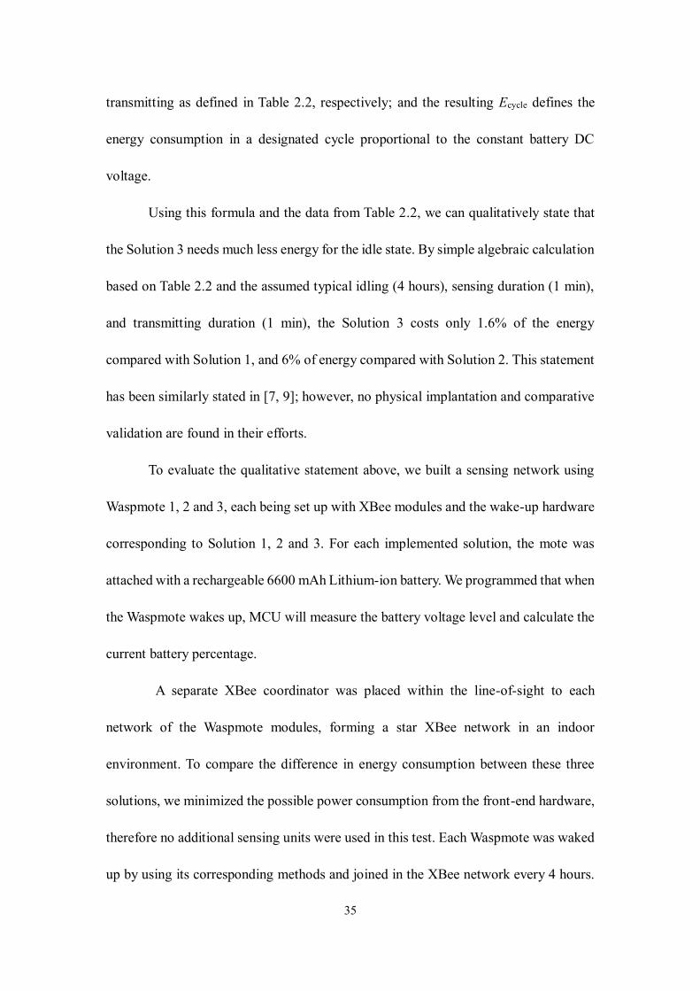
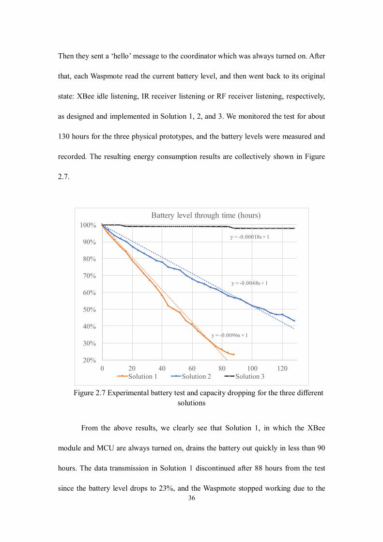
recorded. The resulting energy consumption results are collectively shown in Figure
2.7.
Figure 2.7 Experimental battery test and capacity dropping for the three different
solutions
From the above results, we clearly see that Solution 1, in which the XBee
module and MCU are always turned on, drains the battery out quickly in less than 90
hours. The data transmission in Solution 1 discontinued after 88 hours from the test
since the battery level drops to 23%, and the Waspmote stopped working due to the
y = -0.0096x + 1
y = -0.0048x + 1
y = -0.00018x + 1
20%
30%
40%
50%
60%
70%
80%
90%
100%
0 20 40 60 80 100 120
Battery level through time (hours)
Solution 1 Solution 2 Solution 3
37
voltage is too low. In Solution 2, we can still see a linear drop in the battery level but
with a slower rate than it is in Solution 1. As we stated above, most energy in Solution
2 is consumed by the IR receiver and the MCU, we can conclude that the XBee idle
and listening states consume a large percentage of energy. Although we did not measure
until the mote stopped working for Solution 2, we believe the battery level drop is
linearly on a rate of 0.48% per hour and will last a total of about 208 hours (through
linear fitting with a fixed intercept of 100%). Lastly, the battery level of Solution 3 did
not drop significantly thanks to the RF wake-up solution. Due to the very low dropping
rate, we only measured a 2% drop during the 130-hour test. Assuming a linear rate of
consumption (through the linear fitting in Figure 2.7), we expect that the Solution 3
network would continue working for about 5556 hours (or an about 7.5-month period).
This is a remarkable improvement compared with both Solution 1 and 2.
Last, if all the consumption rates are compared (as shown in the linear fitting in
terms of the slope values), one can see that the power consumption rate from Solution
3 is about 3.8% of Solution 2, and 1.9% of Solution 1. This approximately confirms the
analytical studies previously. In fact, we noted a better result (3.8% instead of 6%) from
the analytical evaluation based on Figure 2.6, when comparing Solution 3 and 2. We
believe this is attributed to that the actual XBee communication time is less than 1 min
since there were not so much data being transferred in this test.
2.7 Conclusion
In this paper, we review the concept of aerial-ground wireless sensing network
(AG-WSN) for its critical use in sensing in a remote and geospatially large or complex
38
space and particularly recognize the need of implementing such sensing solution in
precision agriculture and structural health monitoring practice. We then recognize the
technical challenge towards achieving energy efficiency in the ground sensors.
Different wake-up mechanisms are then reviewed and compared. Among those
mechanisms, we chose active radio frequency (RF) based wake-up method and
implemented physically. The focus is on evaluating their performance to achieve energy
efficiency on the battery-powered ground sensors. The following findings are achieved
through the experimental evaluation in this work:
The experimental results in this paper indicate that the RF-based out-band wake-
up mechanism can save a great deal of energy compared with the other two solutions
(the infrared wake-up and the default duty-cycle methods). A direct comparison
between the RF-based solution and the infrared-based solution indicates that the RF-
based wake-up mechanism has noticeably better performance in the wake-up range, and
has a tremendous improvement in the power consumption. Specifically, the results
show that the RF-based wake-up mechanism can potentially save more than 98.4% of
the energy that the traditional duty-cycle method would otherwise consume, and 96.8%
if an infrared-receiver method is used.
The evaluation of wake-up time-delay by using a variety of different wake-up
signal codes indicate that the time-delay is below 80 milliseconds; hence, the delay will
not affect most opportunistic sensing applications (wherein the sensors sense the data
at a time and transmit at a later time, then the sensors go back to the sleep mode until
another abrupt event). Herein it is pointed out, however, that more strict time-delay
39
evaluation needs to be conducted if synchronization is critical between the sensors.
Given the two findings, it is concluded that the RF wake-up mechanism is the
first candidate for implementing the proposed wireless aerial-ground sensing network
for monitoring applications in large-scale geospatial or challenging spaces. The
technical contribution also includes the use of a digital imaging approach to measuring
the wake-up time-delay; and the resulting time-dependent rates of the battery-based
power consumption using three different wake-up methods. This experimental and
empirical knowledge may be extrapolated in similar sensing network research wherein
sensor activation needs to be integrated.
The technical contribution also includes the use of a digital imaging approach
to measuring the wake-up time-delay; and the resulting battery-based power
consumption rates using three different wake-up methods. This experimental and
empirical knowledge may be extrapolated in similar sensing network research wherein
sensor wake-up needs to be integrated.
40
CHAPTER 3
EXPERIMENTAL INVESTIGATION OF AERIAL-GROUND NETWORK
COMMUNICATION TOWARDS GEOSPATIALLY LARGE-SCALE
STRUCTURAL HEALTH MONITORING
3.1 Introduction
The deficiency of civil infrastructure systems in the US has been recognized as
a national challenge that, if not altered, would have a cascading impact on the nation’s
economy and competitiveness. For the stock of highway bridges in the USA, about
9.1% of them were structurally deficient in 2016 [95]. With the exposure to the
unavoidable natural disasters, highly economical, rapid, and efficient structural
condition and health assessment technologies are of critical importance for ensuring
community resilience. To this end, periodic inspection is the mainstream method for
managing most of the bridges and other civil infrastructure systems, which are time-
consuming, laborious, and expensive. Innovative technologies for civil infrastructure
data collection have been expected to transform this practice.
The state-of-the-art approach is structural health monitoring (SHM), which
features the use of wired or wireless sensors, including the use of smart sensors in
wireless sensing networks (WSNs) [14-17]. Most SHM technologies focus on sensing
of vibrational data (e.g. dynamic acceleration, displacement or local strain data) due to
external excitation, followed by signal processing and system identification methods
for extraction of intrinsic system parameters (e.g. modal frequencies) and states (e.g.
global and local damage proxies). In reality, however, for structures with slight to
41
moderate damage, such as local cracking and corrosion, visual or remote sensing based
inspection is the most efficient approach to date. This is partially due to that in reality,
local damage induced modal changes may be insignificant compared to changes due to
environmental fluctuations (e.g. temperature and humidity) [96]. In contrast to SHM
methodologies, remote sensing-based imaging technology provides a direct means for
assessing structural damage. The underlying basis is that images of structures or
structural components provide pixels that can be viewed as high-resolution ‘sensors’,
which directly convey the appearance characteristics of structural condition. Among
different remote sensing platforms, low-cost and highly mobile small Unmanned Arial
Vehicles (UAVs or commonly called drones, such as quadcopters) are being treated as
an emerging platform [18-20]. The use of such imaging UAVs has been proven
effective in providing overhead imagery for civil infrastructure condition assessment,
although operational challenges exist due to environmental factors.
It is noted that modern UAVs are often equipped with communication modules
and can further carry sensing and routing payloads. This provides the technical
feasibility of incorporating UAVs into a WSN that networks with regular ground-based
sensors. On the other hand, the potential of integration UAVs into a WSN is also
corroborated by a critical challenge in deploying practical WSNs in challenging
environments. For instance, since sensors are usually battery-powered, field sensors are
often deactivated and in the ‘sleep’ mode. Moreover, in a harsh environment or
circumstance such as in disaster scenes where cellular networks are crippled, data may
become ultimately inaccessible even if a local WSN survives. These challenges can be
42
overcome by taking advantage of the aerial mobility of the UAVs. One solution is to
use a UAV to fly to the overhead of the ground WSN, and activate the sensors in an as-
needed basis hence achieving maximum energy efficiency [26]. To access data from a
ground WSN, the UAV may serve as a gateway to receive data from the ground sensors.
It is noted that the concept of integrating UAVs into a WSN or realizing dynamic relay
of communication has been similarly proposed by different researchers [27, 28].
However, no physical prototype or applications of such networks to civil infrastructure
monitoring is found to date.
Recognizing the potential promise of integrating UAV-based imaging and
ground-based WSN in improving the efficiency of collecting civil structures, the
resulting network is termed aerial-ground wireless sensing network (AG-WSN) in this
paper. In an AG-WSN sensing system, the UAV is adapted to achieve two immediate
roles – as an imaging sensor providing overhead imagery and as a gateway (or data
sink) that commands and receives data from the ground sensors. In an earlier effort of
the authors [29], the concept of aerial-imaging and ground-sensing was proposed for
use in the situation of disaster response in a geospatially wide area. In this paper, this
concept is borrowed towards structural monitoring at a geospatial scale as well, wherein
the health and conditions of a single large-scale structure or clustered structures (e.g. in
a wide area such as a city block) are the concern. In recent years, it is noted that small
UAVs are further investigated for the use in an interior or GPS-denied environment
with the assistance of machine-vision based navigation [30, 31]. This implies that the
proposed AG-WSN may be further extended into use in these challenging
43
environments.
Given such promise and towards deploying the proposed AG-WSN, however,
one practical issue that remains not fully resolved is the interference between the UAV’s
and the WSN’s operating frequencies. In practice, most UAVs use 2.4 GHz radio for
flight control and 2.4 GHz Wi-Fi (802.11 g/n/ac) for imagery data feeds. For low-power
sensing, ground-based WSNs often use the ZigBee (802.15.4) protocol, which may run
at 2.4 GHz as well. In this paper, an AG-WSN prototype using commercial components
is developed, and then the interference issue is experimentally explored.
This experimental paper contributes to the body of knowledge in terms of two
empirical findings: (1) the key parameters affecting the short-range Wi-Fi and ZigBee
interference and the experimental relations; and (2) the long-range optimal ZigBee
transmission with the novel definition of the transmission comfort-zone and the
sensitive parameter. Last, it is worth pointing out that the experimental methodology
adopted in this paper is pragmatic towards deploying the proposed AG-WSN for the
integrated monitoring civil structures at a geospatial scale. For analytically
investigating the communication interference issue, rigorous anechoic-chamber studies
are essential, which is often beyond the knowledge domain of civil structural and SHM
engineers.
3.2 System Design and Potential Capabilities
In the proposed AG-WSN solution, the idea is to use a UAV as a remote sensing
platform that feeds imagery data through the Wi-Fi link to the ground station; in the
meantime, the UAV acts as a sink to gather data from ground-based sensing nodes
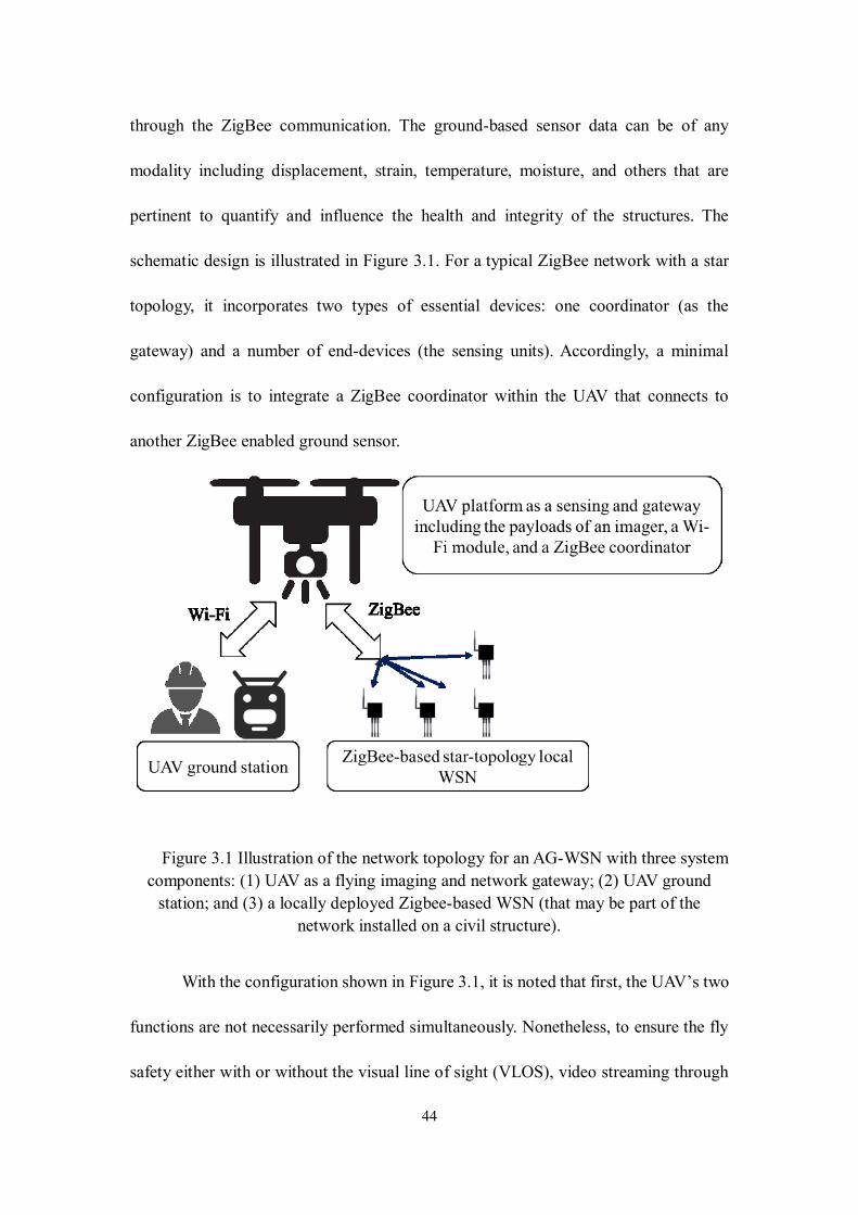
44
through the ZigBee communication. The ground-based sensor data can be of any
modality including displacement, strain, temperature, moisture, and others that are
pertinent to quantify and influence the health and integrity of the structures. The
schematic design is illustrated in Figure 3.1. For a typical ZigBee network with a star
topology, it incorporates two types of essential devices: one coordinator (as the
gateway) and a number of end-devices (the sensing units). Accordingly, a minimal
configuration is to integrate a ZigBee coordinator within the UAV that connects to
another ZigBee enabled ground sensor.
Figure 3.1 Illustration of the network topology for an AG-WSN with three system
components: (1) UAV as a flying imaging and network gateway; (2) UAV ground
station; and (3) a locally deployed Zigbee-based WSN (that may be part of the
network installed on a civil structure).
With the configuration shown in Figure 3.1, it is noted that first, the UAV’s two
functions are not necessarily performed simultaneously. Nonetheless, to ensure the fly
safety either with or without the visual line of sight (VLOS), video streaming through
45
the Wi-Fi link from the UAV to the ground station is critical and should be turned on
continuously. As a result, the underlying communication-interference issue is
outstanding once an AG-WSN is deployed in the field, which is the challenge to resolve
in this paper. With the basic sensing functions of the AG-WSN, three other potential
capabilities and opportunities of an AG-WSN network are envisioned and summarized
as follows.
1. The imaging (including laser-based scanning) payload at the UAV in an
AG-WSN can be used to measure structural displacement remotely
through photogrammetric processing and mathematical optimization.
This promise has been showcased in several recent endeavors with
experimental verification in a laboratory or ideal environment [97-99],
which provide a great promise in overcoming the cost of deploying
contact-based sensors to civil structures in a challenging environment.
However, it is recognized that, first, even considering such logistic
challenges, contact-based sensors are yet essential when obtaining in-
situ environmental measurements (e.g. temperature and moisture etc.)
and the ground-truth structural measurements. In addition, it is asserted
that other significant challenges exist towards direct UAV-imaging
based structural monitoring, such as wind-induced aerodynamic
disturbance and difficulty in achieving UAV-motion invariant estimates
[97].
2. The proposed AG-WSN framework provides the next-generation
46
solution to embedded computing towards the real-time delivery of
structural health analytics. First, although the state-of-the-art wireless
sensors today are equipped with basic onboard or embedded processing
capability, e.g. as found in the sensor boards of Xnode, Imote2, and
WaspMote etc. described in [100], mostly the computing is limited to
simple preprocessing due to computing speed and power consumption.
On the other hand, modern UAVs are usually equipped with a much
more powerful embedded computer (e.g. one used in our research is
powered by a Xilinx SoC that is powered by a dual-core ARM processor
and an FPGA processer) and higher-capacity lithium-ion polymer
batteries, which can be exploited to realize the notion of realistic edge-
computing towards online system identification and damage-scene
understanding [101].
3. As shown in Figure 3.1, the locally deployed WSN on the civil structures
implies that the WSN may be a sub-network of the WSN system for the
monitored structure. This further signifies that the flying UAV can serve
both as an in-situ server in receiving and processing the ground data and
a ‘head’ sensor node for the sub-network in the ground. Through flying
to the next or adjacent sub-network deployed to the structure, this
operational modality provides an unprecedented opportunity for
implementing the well-explored decentralized SHM for a large-scale
structure [14, 102, 103], although significant research challenges are to
47
be recognized; and some envisioned arguments are provided later in this
paper.
3.3 Technical Background in Wi-FI and ZigBee Interference
For the operating frequencies of Wi-Fi and ZigBee, besides several optional
frequency bands (e.g. 868 or 915 MHz for wireless personal area network or WPAN;
and 6 or 60 GHz for wireless local area network or Wi-Fi), industrial Wi-Fi devices
generally use the 2.4 GHz frequency band, which overlaps with the most widely used
2.4 GHz for ZigBee devices. With this sharing of the same frequency band, first of all,
numerous efforts have indicated the presence of ZigBee and Wi-Fi interference in a
close range [104-108]. Second, the fact that small UAVs (e.g. a quadcopter) are size-
sensitive to the addition of flight payloads renders the possible close-range interference
more significant. In the meantime, interference will always trigger higher power
consumption and shorten the aerial endurance besides risking the UAV flight control.
Therefore, an investigation of how Wi-Fi interferes with the low-power ZigBee
communication in a UAV platform is practically needed.
Some researchers attempt to find ways to avoid or resolve the interference when
both networks are deployed. Huang et al. (2010) argued that there exist abundant
opportunities for ZigBee and Wi-Fi to coexist in the same or overlapping channels
[105]. They developed a frame protocol to achieve the trade-off between the throughput
and the packet delivery ratio (PDR). Zhang and Shin (2011) used a frequency flip
scheme to avoid this frequency overlap, in which a ZigBee node is deployed to notify
a nearby Wi-Fi network to prevent mutual interference between the two [108]. A similar
48
idea was reported by using a hybrid device to coordinate messages between the Wi-Fi
and the ZigBee networks [104]. In addition, the work of Xu et al. (2011) developed a
scheme that detects a Wi-Fi network and then automatically changes the ZigBee
channel to avoid interference [107]. Other researchers found that due to the low power
requirement, ZigBee packets are easily corrupted by strong Wi-Fi interference. As such,
one potential solution is to modify the ZigBee packet to potentially reduce the
interference. For instances, Liang et al. (2010) used multi-headers in ZigBee packets
that provide header redundancy to increase PDR and claimed that in most cases, the
ZigBee packet header is the only corrupt zone of the whole packet under the Wi-Fi
interference [106].
There are a few endeavors that aim to evaluate the ZigBee network performance
under Wi-Fi interference through numerical simulation and experimental verification.
Theoretical modeling of ZigBee interference in terms of packet error rate (PER) under
Wi-Fi and Bluetooth was reported [109]. In Yi et al. (2011), the authors adopted this
theoretical model and further verified the simulation by physical testing that the
distance between the Wi-Fi and ZigBee devices and the offset of the center-operating
frequency between the two are the two major factors that affect the ZigBee performance
[110]. They reported that a distance of two meters in most cases would be safe if there
is an offset frequency of 8 MHz between the ZigBee and the Wi-Fi. This is a notable
finding for deploying ZigBee and Wi-Fi networks using commercial products without
considering the aforementioned frequency-based adjustment or packet modification
schemes. However, for considering deployment of a UAV-based network, it is hard to
49
achieve the aforementioned configuration since most commercially available
quadcopter UAVs usually have a form factor less than 2 meters. Another interesting
white paper shows that different ZigBee devices using different chipsets have quite
unique results under the impact of Wi-Fi [111]; hence, technically the shorter distance
may exist. Unfortunately, most commercial ZigBee devices and chipsets including the
ones used in this paper are not in the test results in Thonet et al. (2008). Last, it is
pointed out that although there are analytical models (with numerical evaluation) for
ZigBee interference with Wi-Fi [109, 110], field-based testing is the ultimate approach.
This physical experimentation approach is adopted in this case study.
3.4 Experimental Evaluation
3.4.1 System Prototyping and Testing Environment
As shown in Figure 3.2, an AG-WSN prototype is developed based on a
commercial drone (DJI Phantom 3 Professional) that carries an imaging camera with
the real-time Wi-Fi data link to the ground station. Two Waspmote® sensor boards from
Libelium are used (each with an XBee-based ZigBee communication module made by
Digi with the Silicon Labs EM357 SoC transceiver chipset operating at 2.4GHz) are
used to construct a minimum (two-node) ZigBee network. The native Wi-Fi antenna of
the UAV for video transmission is built into the front-left landing gear. The insert
picture in Figure 3.2 shows the Waspmote board that is attached to the UAV. The other
(identical) Waspmote board is placed at the ground as the end-device.
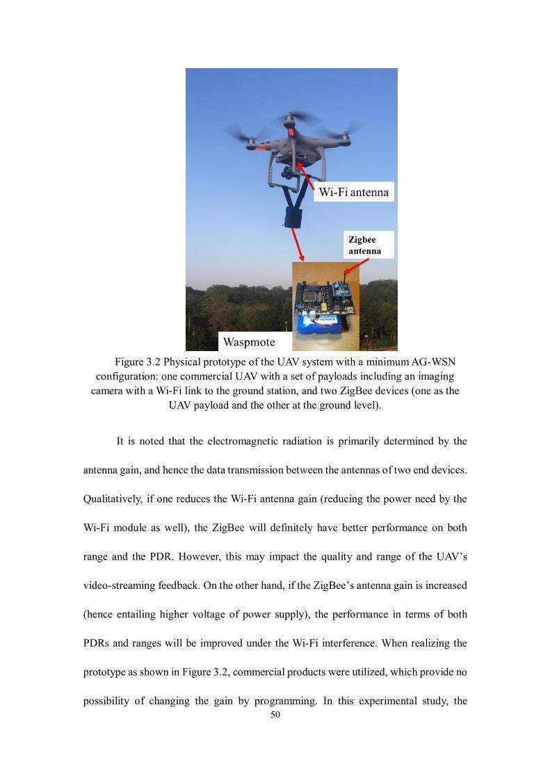
50
Figure 3.2 Physical prototype of the UAV system with a minimum AG-WSN
configuration: one commercial UAV with a set of payloads including an imaging
camera with a Wi-Fi link to the ground station, and two ZigBee devices (one as the
UAV payload and the other at the ground level).
It is noted that the electromagnetic radiation is primarily determined by the
antenna gain, and hence the data transmission between the antennas of two end devices.
Qualitatively, if one reduces the Wi-Fi antenna gain (reducing the power need by the
Wi-Fi module as well), the ZigBee will definitely have better performance on both
range and the PDR. However, this may impact the quality and range of the UAV’s
video-streaming feedback. On the other hand, if the ZigBee’s antenna gain is increased
(hence entailing higher voltage of power supply), the performance in terms of both
PDRs and ranges will be improved under the Wi-Fi interference. When realizing the
prototype as shown in Figure 3.2, commercial products were utilized, which provide no
possibility of changing the gain by programming. In this experimental study, the
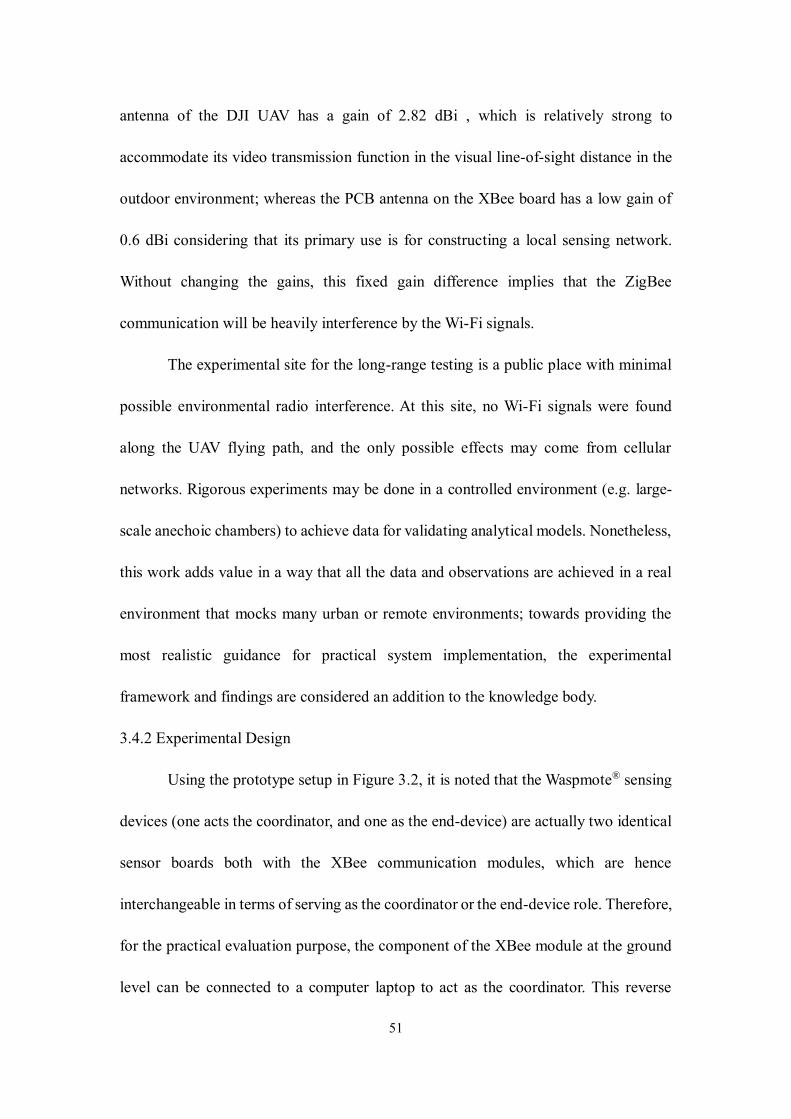
51
antenna of the DJI UAV has a gain of 2.82 dBi , which is relatively strong to
accommodate its video transmission function in the visual line-of-sight distance in the
outdoor environment; whereas the PCB antenna on the XBee board has a low gain of
0.6 dBi considering that its primary use is for constructing a local sensing network.
Without changing the gains, this fixed gain difference implies that the ZigBee
communication will be heavily interference by the Wi-Fi signals.
The experimental site for the long-range testing is a public place with minimal
possible environmental radio interference. At this site, no Wi-Fi signals were found
along the UAV flying path, and the only possible effects may come from cellular
networks. Rigorous experiments may be done in a controlled environment (e.g. large-
scale anechoic chambers) to achieve data for validating analytical models. Nonetheless,
this work adds value in a way that all the data and observations are achieved in a real
environment that mocks many urban or remote environments; towards providing the
most realistic guidance for practical system implementation, the experimental
framework and findings are considered an addition to the knowledge body.
3.4.2 Experimental Design
Using the prototype setup in Figure 3.2, it is noted that the Waspmote® sensing
devices (one acts the coordinator, and one as the end-device) are actually two identical
sensor boards both with the XBee communication modules, which are hence
interchangeable in terms of serving as the coordinator or the end-device role. Therefore,
for the practical evaluation purpose, the component of the XBee module at the ground
level can be connected to a computer laptop to act as the coordinator. This reverse
52
configuration is convenient since the XBee-laptop platform can readily run the
developed testing program to conduct the evaluation. To ensure the likely interference
minimized at the ground, a 10-meter distance is kept between the ZigBee coordinator
and the UAV’s base station. With the prototype system in the air shown in Figure 3.2,
Figure 3.3 illustrates the primary configuration and the geometric variables for the
interference evaluation: D – the distance between the UAV and the laptop; d – the
distance between the Wi-Fi and ZigBee (XBee) antennas; and θ – the relative angle
between the two antennas in the UAV configuration space.
Figure 3.3. Illustration of the experimental setup and the configuration variables.
To minimize other possible factors that may affect the test result, the Wi-Fi
center frequency was set precisely at 2486 MHz and ZigBee center frequency at 2455
MHz according to Yi et al. (2011), which states that the larger frequency offset between
these two, the less interference is likely to occur when the distance between Wi-Fi and
53
ZigBee stays the same. Second, the power of the Wi-Fi and the ZigBee modules are
both set as a fixed value. During the testing, the UAV maintains communication with
the ground station using the Wi-Fi channel and sends the video feed to the station. The
ZigBee coordinator at the ground is controlled to send packets of 50 bytes repeatedly
to the end-device attached to the UAV (both the coordinator and the end-device have
the same XBee antennas). The end-device then returns the received data back to the
coordinator. By monitoring the number of packets that travel back to the coordinator,
the PDR (Packet Delivery Ratio) is defined and measured:
PDR =Number of packets Returned
Total number of packets sent out× 100%
In the following tests, a total of 1000 packets are sent to calculate the PDR at a
prescribed condition.
3.4.3 Test-1: Interference at Short-range Communication
In an initial test with no Wi-Fi interference (where the UAV was turned off
without video feeding and the UAV is moved away from the Zigbee coordinator), the
ZigBee coordinator and the ZigBee end-device was found to be able to communicate
at a 99.6% PDR at 800 meters (which is the maximum the line-of-sight distance
considered in this paper). When the Wi-Fi was turned on (UAV was turned on, and the
standard video, 720p/6000kbps/30fps, is feeding to the base station), it was found that
the interference became dramatic with the PDR less than 50%. To observe the effects
of the relative positions of the Wi-Fi and the ZigBee antennas, the set up shown in
Figure 3.3 was used, in which the UAV and the ZigBee coordinator distance (shown as
D in Figure 3.3) was set 5 meters, while the UAV was set hovering with the Wi-Fi video
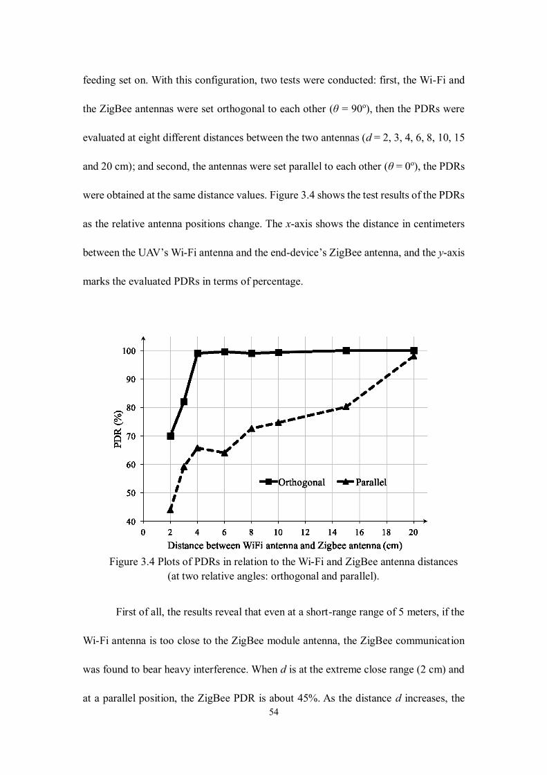
54
feeding set on. With this configuration, two tests were conducted: first, the Wi-Fi and
the ZigBee antennas were set orthogonal to each other (θ = 90o), then the PDRs were
evaluated at eight different distances between the two antennas (d = 2, 3, 4, 6, 8, 10, 15
and 20 cm); and second, the antennas were set parallel to each other (θ = 0o), the PDRs
were obtained at the same distance values. Figure 3.4 shows the test results of the PDRs
as the relative antenna positions change. The x-axis shows the distance in centimeters
between the UAV’s Wi-Fi antenna and the end-device’s ZigBee antenna, and the y-axis
marks the evaluated PDRs in terms of percentage.
Figure 3.4 Plots of PDRs in relation to the Wi-Fi and ZigBee antenna distances
(at two relative angles: orthogonal and parallel).
First of all, the results reveal that even at a short-range range of 5 meters, if the
Wi-Fi antenna is too close to the ZigBee module antenna, the ZigBee communication
was found to bear heavy interference. When d is at the extreme close range (2 cm) and
at a parallel position, the ZigBee PDR is about 45%. As the distance d increases, the
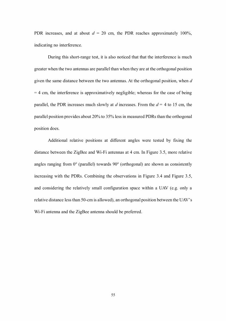
55
PDR increases, and at about d = 20 cm, the PDR reaches approximately 100%,
indicating no interference.
During this short-range test, it is also noticed that that the interference is much
greater when the two antennas are parallel than when they are at the orthogonal position
given the same distance between the two antennas. At the orthogonal position, when d
= 4 cm, the interference is approximatively negligible; whereas for the case of being
parallel, the PDR increases much slowly at d increases. From the d = 4 to 15 cm, the
parallel position provides about 20% to 35% less in measured PDRs than the orthogonal
position does.
Additional relative positions at different angles were tested by fixing the
distance between the ZigBee and Wi-Fi antennas at 4 cm. In Figure 3.5, more relative
angles ranging from 0o (parallel) towards 90o (orthogonal) are shown as consistently
increasing with the PDRs. Combining the observations in Figure 3.4 and Figure 3.5,
and considering the relatively small configuration space within a UAV (e.g. only a
relative distance less than 50-cm is allowed), an orthogonal position between the UAV’s
Wi-Fi antenna and the ZigBee antenna should be preferred.
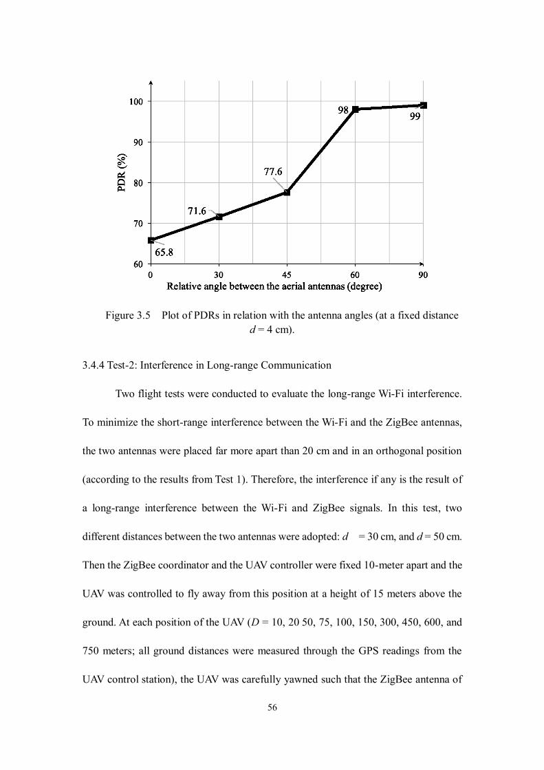
56
Figure 3.5 Plot of PDRs in relation with the antenna angles (at a fixed distance
d = 4 cm).
3.4.4 Test-2: Interference in Long-range Communication
Two flight tests were conducted to evaluate the long-range Wi-Fi interference.
To minimize the short-range interference between the Wi-Fi and the ZigBee antennas,
the two antennas were placed far more apart than 20 cm and in an orthogonal position
(according to the results from Test 1). Therefore, the interference if any is the result of
a long-range interference between the Wi-Fi and ZigBee signals. In this test, two
different distances between the two antennas were adopted: d = 30 cm, and d = 50 cm.
Then the ZigBee coordinator and the UAV controller were fixed 10-meter apart and the
UAV was controlled to fly away from this position at a height of 15 meters above the
ground. At each position of the UAV (D = 10, 20 50, 75, 100, 150, 300, 450, 600, and
750 meters; all ground distances were measured through the GPS readings from the
UAV control station), the UAV was carefully yawned such that the ZigBee antenna of
57
the end device in the UAV is parallel with the ZigBee coordinator’s antenna to keep
maximum signal strength. At each distance, the UAV hovered until one PDR test was
done. The test is done over a flat field that is approximately 60 meters wide and 800
meters long. Figure 3.6 illustrates the test field and the flight path.
Figure 3.6 Flight field and path for the long-range interference test (courtesy of
Google Map).
Figure 3.7 shows that when the distance d between the UAV’s Wi-Fi and ZigBee
antenna is 30 cm, the ZigBee communication can overcome the Wi-Fi interference
(with a PDR close to 100%) as long as the communication distance (between the
coordinator at the ground and the end-device in the air) is within 50 meters. When d
increases to 50 cm, the distance of 100 meters is a greater threshold for the ZigBee
communication to overcome the Wi-Fi interference. In this paper, this threshold for
achieving negligible interference is defined as a ZigBee communication ‘comfort zone’
for UAV-based long-range mixed Wi-Fi and ZigBee data transmission.
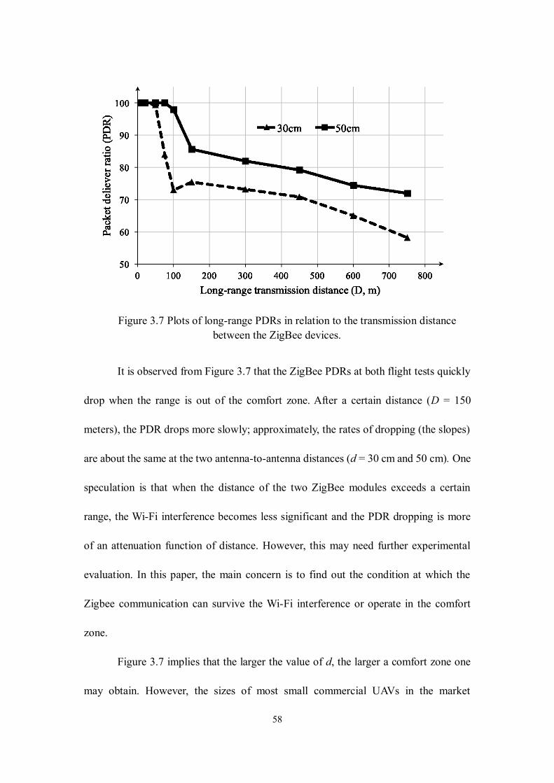
58
Figure 3.7 Plots of long-range PDRs in relation to the transmission distance
between the ZigBee devices.
It is observed from Figure 3.7 that the ZigBee PDRs at both flight tests quickly
drop when the range is out of the comfort zone. After a certain distance (D = 150
meters), the PDR drops more slowly; approximately, the rates of dropping (the slopes)
are about the same at the two antenna-to-antenna distances (d = 30 cm and 50 cm). One
speculation is that when the distance of the two ZigBee modules exceeds a certain
range, the Wi-Fi interference becomes less significant and the PDR dropping is more
of an attenuation function of distance. However, this may need further experimental
evaluation. In this paper, the main concern is to find out the condition at which the
Zigbee communication can survive the Wi-Fi interference or operate in the comfort
zone.
Figure 3.7 implies that the larger the value of d, the larger a comfort zone one
may obtain. However, the sizes of most small commercial UAVs in the market
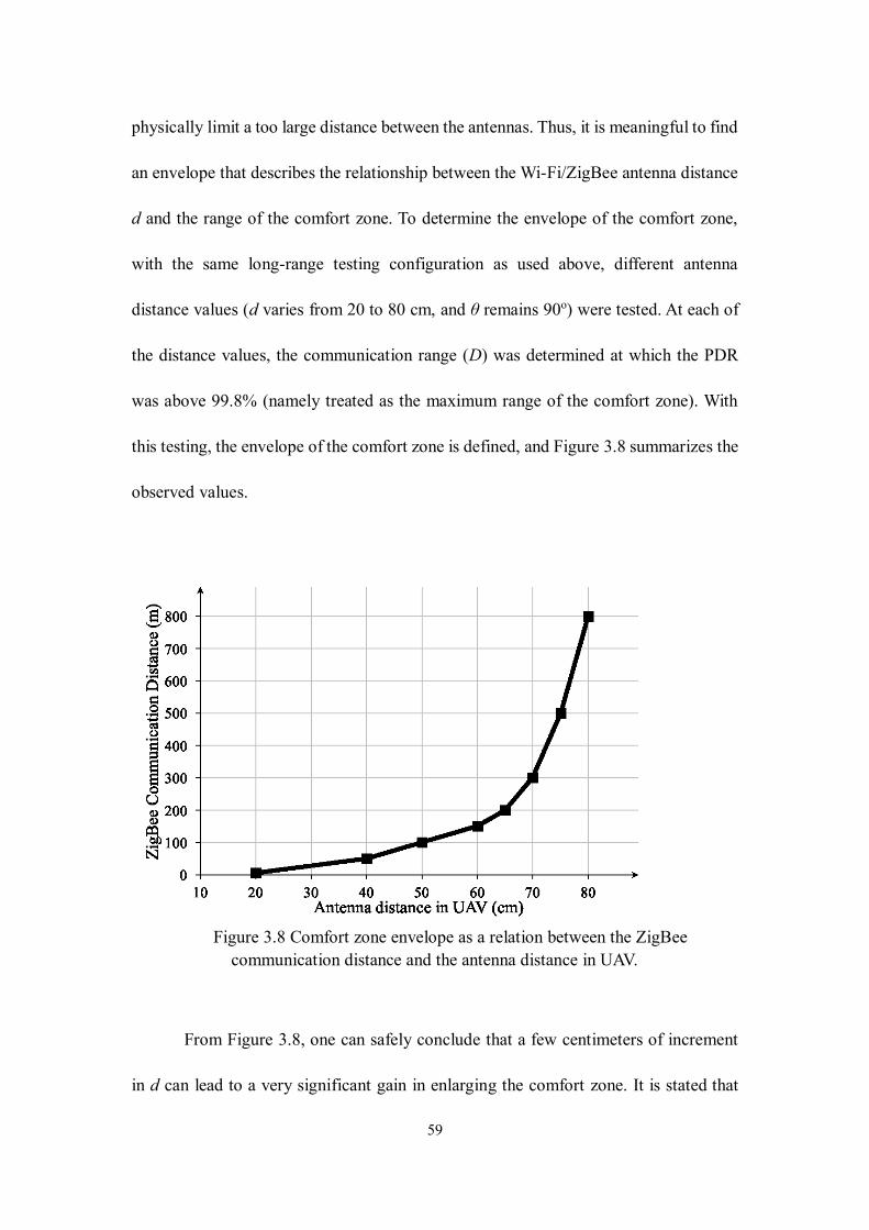
59
physically limit a too large distance between the antennas. Thus, it is meaningful to find
an envelope that describes the relationship between the Wi-Fi/ZigBee antenna distance
d and the range of the comfort zone. To determine the envelope of the comfort zone,
with the same long-range testing configuration as used above, different antenna
distance values (d varies from 20 to 80 cm, and θ remains 90o) were tested. At each of
the distance values, the communication range (D) was determined at which the PDR
was above 99.8% (namely treated as the maximum range of the comfort zone). With
this testing, the envelope of the comfort zone is defined, and Figure 3.8 summarizes the
observed values.
Figure 3.8 Comfort zone envelope as a relation between the ZigBee
communication distance and the antenna distance in UAV.
From Figure 3.8, one can safely conclude that a few centimeters of increment
in d can lead to a very significant gain in enlarging the comfort zone. It is stated that
60
this result is not found in the literature, which can assist the implementation of the
proposed AG-WSN, especially when a commercial UAV is considered that comes with
a small form-factor and limitation for adding payloads.
3.5 Discussion
Towards deploying the proposed AG-WSN network to large-scale structures or
structure clusters, there exist several major challenges. These challenges are described
as follows and the solutions that may partially resolve these challenges are suggested
as well.
Environmental and operational challenges. This category of challenges includes
the operation of UAVs (especially the multi-rotor copters) during a vehement weather
condition (e.g. heavy raining, high-wind, and very low-visibility days). If the camera is
used to measure structural displacement, as indicated in [97, 98], these challenges are
not fully resolved to this end. For instance, the wind-induced aerodynamic disturbance
to the UAV will violate the ‘small-rotation’ assumption for the UAV towards extracting
the true structural displacement from the images. Even with a benign weather condition,
the UAV in the field may often fly out of the plane when imaging the structure that
violates the in-plane motion assumption. With these challenges that are present to date,
contact-based wireless sensors are still poised to be the most reliable solution to this
end, which further ratifies the value of the proposed UAV-based AG-WSN solution. As
it is pointed out previously that since the primary goal of flying the UAV in our
proposed solution is not to employ the imaging payload to ‘measure’ structural
61
displacement, moderate weather conditions should be acceptable if the UAV is capable
of flying from an operational safety point of view, as long as the data links are
operational between the UAV and the ground sensors. Another operational challenge is
automatic obstacle avoidance when deploying the UAV over a complex space (e.g. in a
dense urban environment). If the UAV flies too close to the structures, amid the complex
aerodynamic effect (similar to the near-ground effect for any plane when landing) the
UAV needs to be equipped with an automatic obstacle-avoidance capability using a
vision or radar-based approach [112, 113].
Energy optimization challenge. When performing monitoring over a geospatial
wide-area with multiple structures and numerous local sensor networks, the UAV needs
to fly over these structures or sensors of interest. Given the limitation of battery
technology to date, the UAV needs to fly to all locations with an optimal path that
minimizes the energy cost. Theoretically, this belongs to the traditional traveling
salesman problem (TSP). With the experimental efforts and findings in this paper,
particularly the recognition of the ‘conform-zone’ radius when transmitting data in a
long distance, the resulting problem becomes a traveling salesman with neighborhood
problem (TSNP), and several analytical solutions can be found in [114, 115].
Optimized sub-structuring for sensor placement (or sub-networking topology),
and the development of decentralized sensing and computing. As described previously,
the proposed AG-WSN provides an unprecedented opportunity of implementing a SHM
solution based on decentralized sensing, wherein the UAV serves as a dynamic ‘head
sensor’ for a local sub-network and a real-time ‘edge-computing’ server. However,
62
several research challenges can be recognized. It first challenges the validity of the
existing decentralized system-identification algorithms (e.g. the random decrement
method in [102]), considering the great flexibility due to the ‘flying’ mechanism of the
UAV. Second, the network topology is not geospatially static but dynamic due to the
airborne flexibility of the UAV as the mobile gateway, which belongs to the arena of
opportunistic routing; and several UAV-based solutions are explored in the literature
[116-118]. The aforementioned energy optimization additionally imparts more
constraints to the problem.
3.6 Conclusion and future work
In this paper, starting with the motivation of developing a UAV-based aerial-
ground WSN for realizing integrated remote sensing and structural health monitoring,
the potential interference issue between Wi-Fi and ZigBee communication is
experimentally investigated. By developing a prototype system with the commercial
components, this case-study paper determines the key factors that affect short-range
interference and the long-range data transmission performance. It is observed that the
relative position of the Wi-Fi and ZigBee antennas and the distance between them are
the two major factors that impact the communication. In the long-range experiment, the
ZigBee data transmission is tested as the range varies up to 800 meters (the line-of-
sight distance). Defining the range with the packet delivery rate of 99.8% as the ZigBee
‘comfort zone’, the effect of the ZigBee/Wi-Fi antenna distance is further determined
and recognized as a sensitive parameter. It is found that with a few centimeters of
increment in this distance, the comfort zone range can be improved significantly.
63
It is worth mentioning that this test result is based on the specific UAV and
ZigBee modules that are commercially acquired. Nonetheless, the experimentation
framework should be applicable to other commercial products, and similar relations as
reported in this study should be expected. Moreover, the findings in this paper provide
the guideline in designing the mixed communication configuration in deploying the
proposed aerial-ground sensing network wherein Wi-Fi and ZigBee networking are
both involved, especially when the ranges of operating frequencies at both overlap.
Two important parameters that may impact the Zigbee PDR, the Wi-Fi video
feed quality and the power level for both Wi-Fi and Zigbee radio, need to be further
investigated in the future. In the current experimental setup, the video feed quality is
not changeable, nor the power level. On the other hand, Zigbee communication may
indeed impact the UAV Wi-Fi/video feed quality, which can be another research focus
using the setup that comes with adjustable video-streaming quality and power levels in
the UAV.
It is noted that in this effort that focuses on defining the concept of the aerial-
ground wireless sensing and investigating the network interference within such a novel
network, realistic structural response and environmental data are not analyzed. The
future efforts based on finding in this paper include the development of heterogeneous
sensing including low-speed environmental sensing (e.g. temperature and moisture data
at a rate of one data point per minute) and fast structural sensing (e.g. acceleration data
at a rate of 200 points per second), and the aerial real-time data acquisition and
computing. The subsequent investigation will include the implementation of a
64
decentralized sensing solution that is optimized for either a single large-scale structure
or a geospatially-large structure clusters in an urban area. The implementation task
further includes the edge-computing based data processing and system identification
towards fully real-time flying, sensing, and delivering of structural health and condition
assessment analytics.
65
CHAPTER 4
SPATIAL PATH-ENERGY OPTIMIZATION FOR TACTIC UNMANNED AERIAL
VEHICLES OPERATION IN ARIAL-GROUND NETWORKING
4.1 Introduction
With advances in autonomous navigation, positioning, mechatronics, and in
general robotics technologies, small to miniature-sized unmanned aerial vehicles
(UAVs; or colloquially called drones) are becoming much low-cost, agile and effective,
hence witnessing their ever-increasing use in many social / economic sectors. Today’s
professional UAVs are usually equipped with the latest GPS technology; and many
small UAVs, especially the multi-motor ones can fly following the predetermined GPS
waypoints. Some advanced drones possess small form-factor radar or vision sensors
that enable its sense-and-avoid capability [45-47], and therefore fly beyond (visual)
line-of-sight (BVLOS or BLOS).
On the other hand, particularly for the multi-rotor UAVs which can take off
vertically and fly at a hovering mode, waypoint-based flight control is not critical. As a
matter of fact, flying over many pre-determined or locations opportunistically or as
demanded in the real-time becomes a very attractive feature. Three examples are
illustrated herein. First, one of the most popular use of UAVs is to provide visual
monitoring or surveillance data through its camera payload, from which 2-dimesnioanl
(2D) or even 3D mapping products can be rapidly obtained. This capability is found
useful and effective in many arenas in the architecture, engineering, and construction
(ACE) industries, precision agriculture, environmental monitoring, disaster and
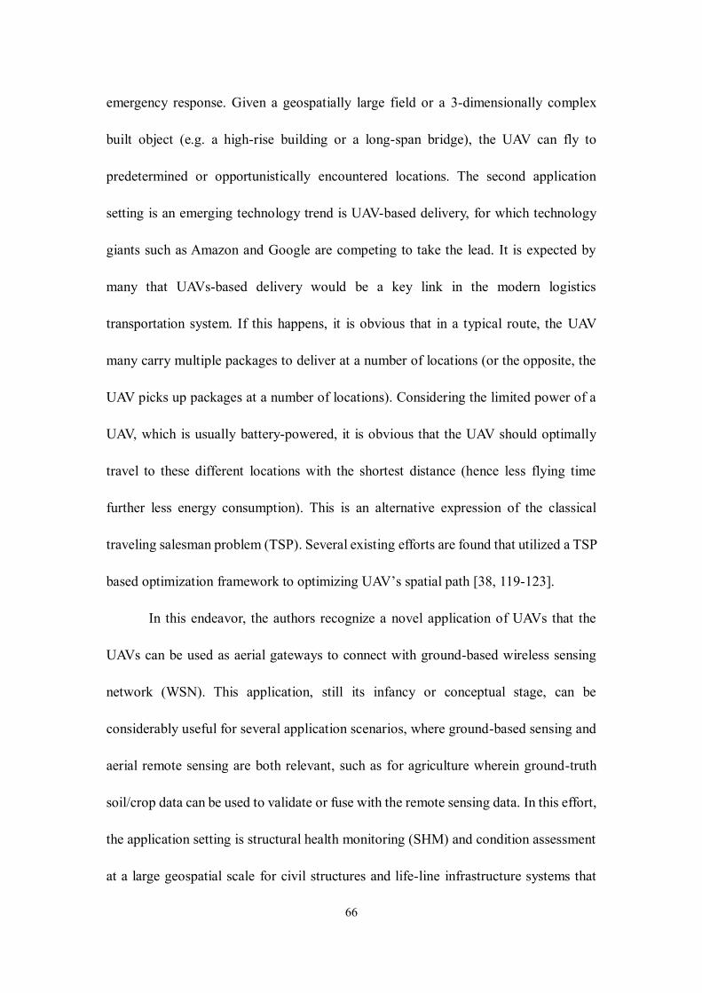
66
emergency response. Given a geospatially large field or a 3-dimensionally complex
built object (e.g. a high-rise building or a long-span bridge), the UAV can fly to
predetermined or opportunistically encountered locations. The second application
setting is an emerging technology trend is UAV-based delivery, for which technology
giants such as Amazon and Google are competing to take the lead. It is expected by
many that UAVs-based delivery would be a key link in the modern logistics
transportation system. If this happens, it is obvious that in a typical route, the UAV
many carry multiple packages to deliver at a number of locations (or the opposite, the
UAV picks up packages at a number of locations). Considering the limited power of a
UAV, which is usually battery-powered, it is obvious that the UAV should optimally
travel to these different locations with the shortest distance (hence less flying time
further less energy consumption). This is an alternative expression of the classical
traveling salesman problem (TSP). Several existing efforts are found that utilized a TSP
based optimization framework to optimizing UAV’s spatial path [38, 119-123].
In this endeavor, the authors recognize a novel application of UAVs that the
UAVs can be used as aerial gateways to connect with ground-based wireless sensing
network (WSN). This application, still its infancy or conceptual stage, can be
considerably useful for several application scenarios, where ground-based sensing and
aerial remote sensing are both relevant, such as for agriculture wherein ground-truth
soil/crop data can be used to validate or fuse with the remote sensing data. In this effort,
the application setting is structural health monitoring (SHM) and condition assessment
at a large geospatial scale for civil structures and life-line infrastructure systems that
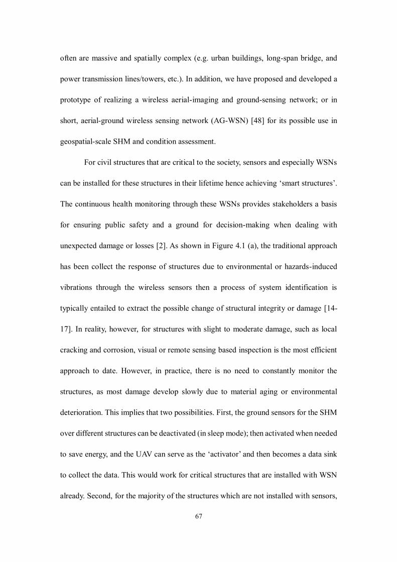
67
often are massive and spatially complex (e.g. urban buildings, long-span bridge, and
power transmission lines/towers, etc.). In addition, we have proposed and developed a
prototype of realizing a wireless aerial-imaging and ground-sensing network; or in
short, aerial-ground wireless sensing network (AG-WSN) [48] for its possible use in
geospatial-scale SHM and condition assessment.
For civil structures that are critical to the society, sensors and especially WSNs
can be installed for these structures in their lifetime hence achieving ‘smart structures’.
The continuous health monitoring through these WSNs provides stakeholders a basis
for ensuring public safety and a ground for decision-making when dealing with
unexpected damage or losses [2]. As shown in Figure 4.1 (a), the traditional approach
has been collect the response of structures due to environmental or hazards-induced
vibrations through the wireless sensors then a process of system identification is
typically entailed to extract the possible change of structural integrity or damage [14-
17]. In reality, however, for structures with slight to moderate damage, such as local
cracking and corrosion, visual or remote sensing based inspection is the most efficient
approach to date. However, in practice, there is no need to constantly monitor the
structures, as most damage develop slowly due to material aging or environmental
deterioration. This implies that two possibilities. First, the ground sensors for the SHM
over different structures can be deactivated (in sleep mode); then activated when needed
to save energy, and the UAV can serve as the ‘activator’ and then becomes a data sink
to collect the data. This would work for critical structures that are installed with WSN
already. Second, for the majority of the structures which are not installed with sensors,
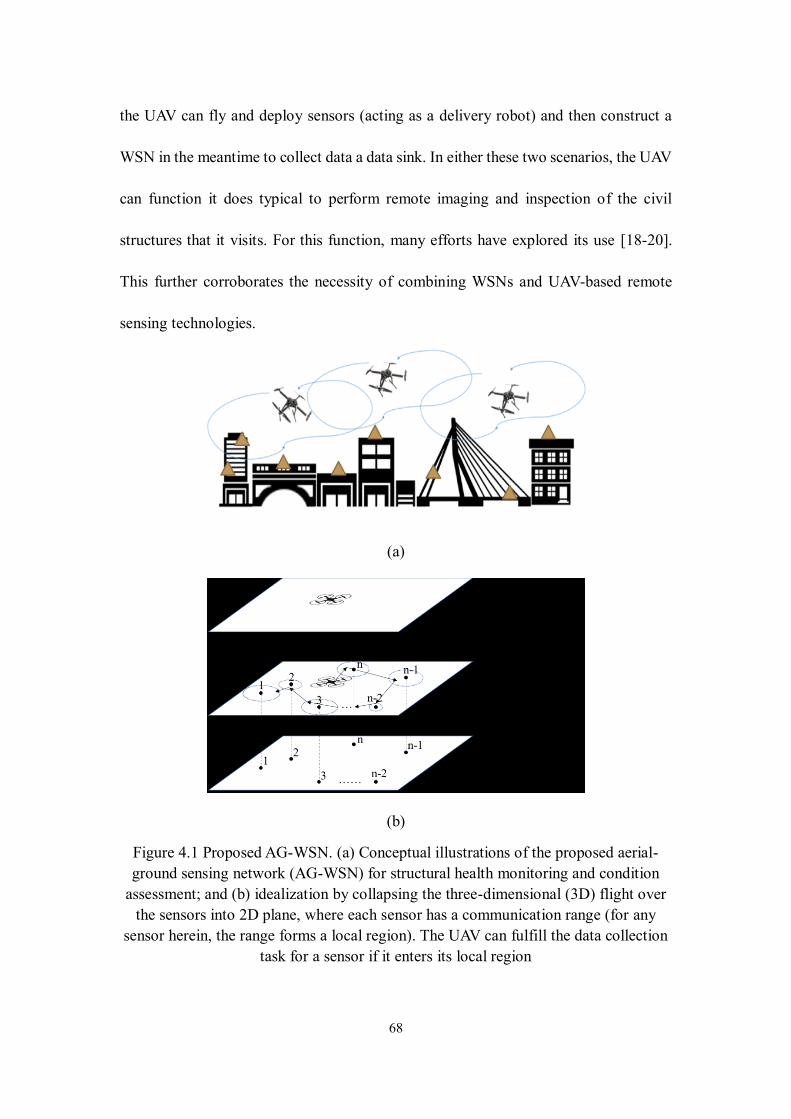
68
the UAV can fly and deploy sensors (acting as a delivery robot) and then construct a
WSN in the meantime to collect data a data sink. In either these two scenarios, the UAV
can function it does typical to perform remote imaging and inspection of the civil
structures that it visits. For this function, many efforts have explored its use [18-20].
This further corroborates the necessity of combining WSNs and UAV-based remote
sensing technologies.
(a)
(b)
Figure 4.1 Proposed AG-WSN. (a) Conceptual illustrations of the proposed aerial-
ground sensing network (AG-WSN) for structural health monitoring and condition
assessment; and (b) idealization by collapsing the three-dimensional (3D) flight over
the sensors into 2D plane, where each sensor has a communication range (for any
sensor herein, the range forms a local region). The UAV can fulfill the data collection
task for a sensor if it enters its local region
69
Given the aforementioned description of the AG-WSN concept for geospatially
large-scale SHM and condition assessment, one may recognize that the primary energy
constraint for the UAV does not vanish as it is described for the UAV-based parcel
delivery or pickup context. Nonetheless, in this effort, it is further identified that the
problem is not a typical TSP problem towards minimizing the energy cost, in which the
travel aims to precisely reach isolated points (at the sensor nodes). The primary
difference is that the UAV is not necessary to fly exactly to the ‘node’ point of the
ground sensor in order to collect data; instead, as long as it reaches a communication
range despite the possible packet loss in communication, the task of data collection can
be completed. Assuming that the sensors are in one plane and the UAV flies in a parallel
plane, either the spatial topology of the sensors or the UAV and its flight paths can be
projected onto one unified plane (a virtual configuration plane). As illustrated in Figure
4.1(b), this implies that the UAV needs to find the paths to visit the communication
ranges (i.e. neighborhoods) of the individual sensor nodes once and collect data from
all nodes with the minimal energy cost. This problem is a generalization of TSB, and is
essentially the Traveling Salesman Problem with Neighborhoods (TSPN).
With this proposition, this paper formulates the TSPN problem in the context of
spatial path-energy optimization for a UAV-based AG-WSN system. Through
exploiting a non-convex mixed-integer nonlinear programming (MINLP) framework,
this paper concerns three novel and related contributions. First, when constructing the
objective function, a new communication range function with package loss is
considered. Second, when defining the objective path-energy function, both the energy
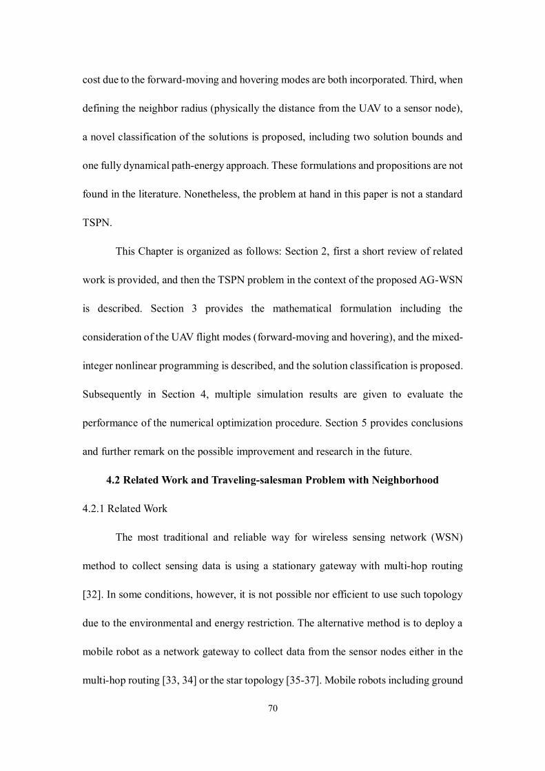
70
cost due to the forward-moving and hovering modes are both incorporated. Third, when
defining the neighbor radius (physically the distance from the UAV to a sensor node),
a novel classification of the solutions is proposed, including two solution bounds and
one fully dynamical path-energy approach. These formulations and propositions are not
found in the literature. Nonetheless, the problem at hand in this paper is not a standard
TSPN.
This Chapter is organized as follows: Section 2, first a short review of related
work is provided, and then the TSPN problem in the context of the proposed AG-WSN
is described. Section 3 provides the mathematical formulation including the
consideration of the UAV flight modes (forward-moving and hovering), and the mixed-
integer nonlinear programming is described, and the solution classification is proposed.
Subsequently in Section 4, multiple simulation results are given to evaluate the
performance of the numerical optimization procedure. Section 5 provides conclusions
and further remark on the possible improvement and research in the future.
4.2 Related Work and Traveling-salesman Problem with Neighborhood
4.2.1 Related Work
The most traditional and reliable way for wireless sensing network (WSN)
method to collect sensing data is using a stationary gateway with multi-hop routing
[32]. In some conditions, however, it is not possible nor efficient to use such topology
due to the environmental and energy restriction. The alternative method is to deploy a
mobile robot as a network gateway to collect data from the sensor nodes either in the
multi-hop routing [33, 34] or the star topology [35-37]. Mobile robots including ground
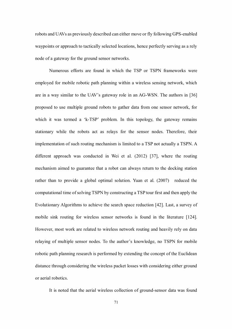
71
robots and UAVs as previously described can either move or fly following GPS-enabled
waypoints or approach to tactically selected locations, hence perfectly serving as a rely
node of a gateway for the ground sensor networks.
Numerous efforts are found in which the TSP or TSPN frameworks were
employed for mobile robotic path planning within a wireless sensing network, which
are in a way similar to the UAV’s gateway role in an AG-WSN. The authors in [36]
proposed to use multiple ground robots to gather data from one sensor network, for
which it was termed a ‘k-TSP’ problem. In this topology, the gateway remains
stationary while the robots act as relays for the sensor nodes. Therefore, their
implementation of such routing mechanism is limited to a TSP not actually a TSPN. A
different approach was conducted in Wei et al. (2012) [37], where the routing
mechanism aimed to guarantee that a robot can always return to the docking station
rather than to provide a global optimal solution. Yuan et al. (2007) reduced the
computational time of solving TSPN by constructing a TSP tour first and then apply the
Evolutionary Algorithms to achieve the search space reduction [42]. Last, a survey of
mobile sink routing for wireless sensor networks is found in the literature [124].
However, most work are related to wireless network routing and heavily rely on data
relaying of multiple sensor nodes. To the author’s knowledge, no TSPN for mobile
robotic path planning research is performed by extending the concept of the Euclidean
distance through considering the wireless packet losses with considering either ground
or aerial robotics.
It is noted that the aerial wireless collection of ground-sensor data was found
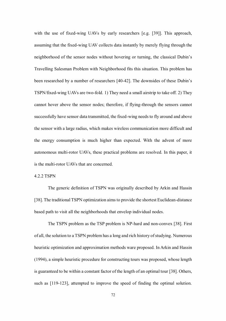
72
with the use of fixed-wing UAVs by early researchers [e.g. [39]]. This approach,
assuming that the fixed-wing UAV collects data instantly by merely flying through the
neighborhood of the sensor nodes without hovering or turning, the classical Dubin’s
Travelling Salesman Problem with Neighborhood fits this situation. This problem has
been researched by a number of researchers [40-42]. The downsides of these Dubin’s
TSPN/fixed-wing UAVs are two-fold. 1) They need a small airstrip to take off. 2) They
cannot hover above the sensor nodes; therefore, if flying-through the sensors cannot
successfully have sensor data transmitted, the fixed-wing needs to fly around and above
the sensor with a large radius, which makes wireless communication more difficult and
the energy consumption is much higher than expected. With the advent of more
autonomous multi-rotor UAVs, these practical problems are resolved. In this paper, it
is the multi-rotor UAVs that are concerned.
4.2.2 TSPN
The generic definition of TSPN was originally described by Arkin and Hassin
[38]. The traditional TSPN optimization aims to provide the shortest Euclidean-distance
based path to visit all the neighborhoods that envelop individual nodes.
The TSPN problem as the TSP problem is NP-hard and non-convex [38]. First
of all, the solution to a TSPN problem has a long and rich history of studying. Numerous
heuristic optimization and approximation methods ware proposed. In Arkin and Hassin
(1994), a simple heuristic procedure for constructing tours was proposed, whose length
is guaranteed to be within a constant factor of the length of an optimal tour [38]. Others,
such as [119-123], attempted to improve the speed of finding the optimal solution.
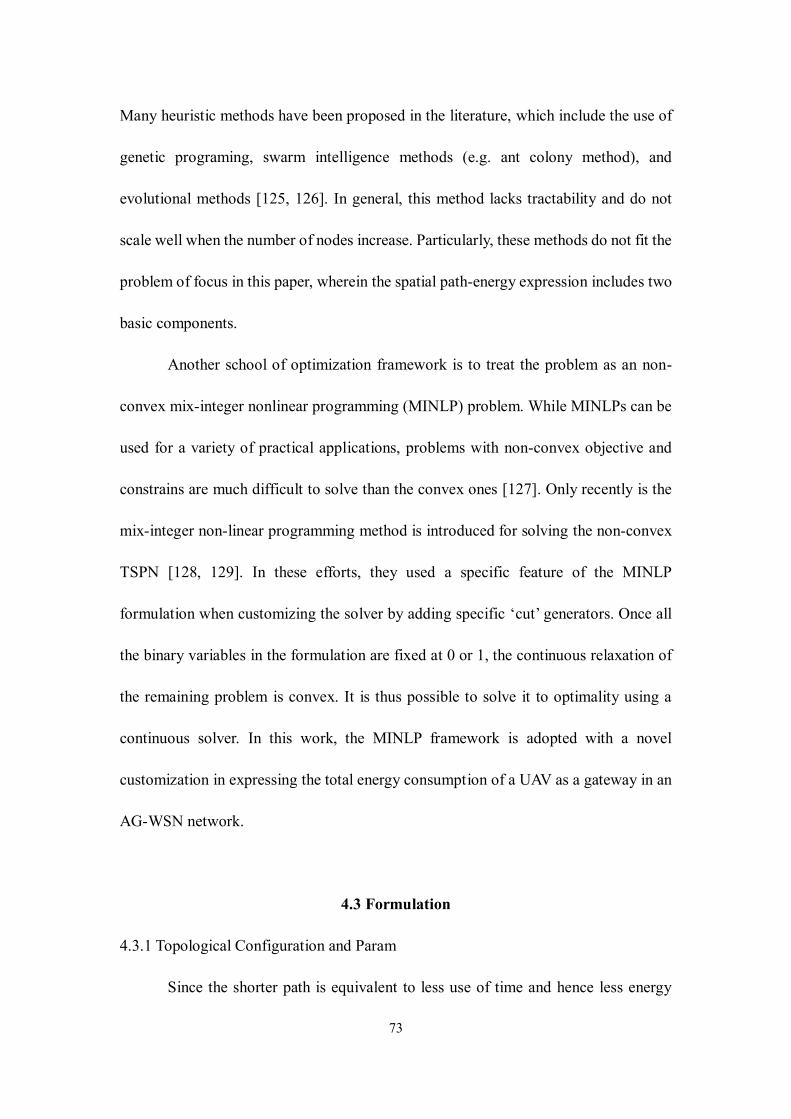
73
Many heuristic methods have been proposed in the literature, which include the use of
genetic programing, swarm intelligence methods (e.g. ant colony method), and
evolutional methods [125, 126]. In general, this method lacks tractability and do not
scale well when the number of nodes increase. Particularly, these methods do not fit the
problem of focus in this paper, wherein the spatial path-energy expression includes two
basic components.
Another school of optimization framework is to treat the problem as an non-
convex mix-integer nonlinear programming (MINLP) problem. While MINLPs can be
used for a variety of practical applications, problems with non-convex objective and
constrains are much difficult to solve than the convex ones [127]. Only recently is the
mix-integer non-linear programming method is introduced for solving the non-convex
TSPN [128, 129]. In these efforts, they used a specific feature of the MINLP
formulation when customizing the solver by adding specific ‘cut’ generators. Once all
the binary variables in the formulation are fixed at 0 or 1, the continuous relaxation of
the remaining problem is convex. It is thus possible to solve it to optimality using a
continuous solver. In this work, the MINLP framework is adopted with a novel
customization in expressing the total energy consumption of a UAV as a gateway in an
AG-WSN network.
4.3 Formulation
4.3.1 Topological Configuration and Param
Since the shorter path is equivalent to less use of time and hence less energy
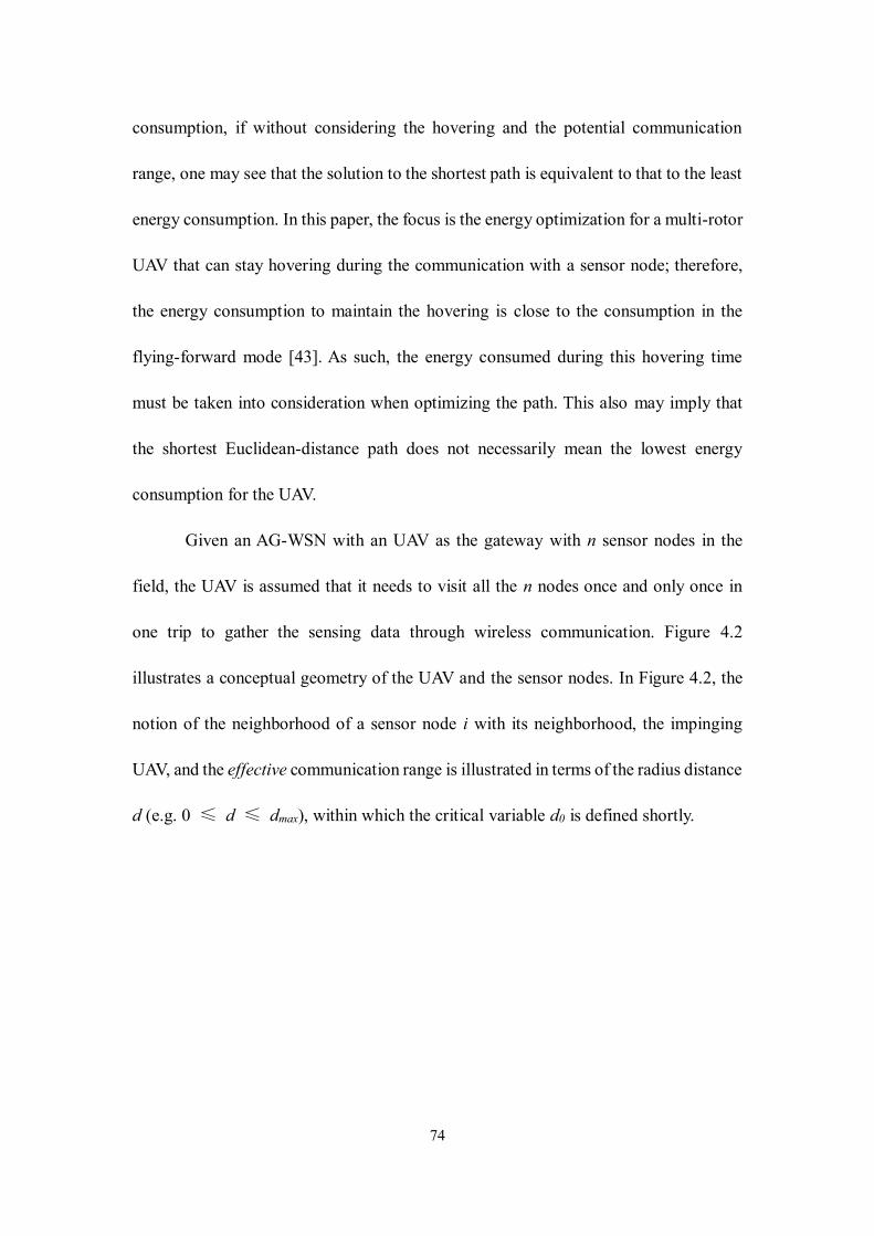
74
consumption, if without considering the hovering and the potential communication
range, one may see that the solution to the shortest path is equivalent to that to the least
energy consumption. In this paper, the focus is the energy optimization for a multi-rotor
UAV that can stay hovering during the communication with a sensor node; therefore,
the energy consumption to maintain the hovering is close to the consumption in the
flying-forward mode [43]. As such, the energy consumed during this hovering time
must be taken into consideration when optimizing the path. This also may imply that
the shortest Euclidean-distance path does not necessarily mean the lowest energy
consumption for the UAV.
Given an AG-WSN with an UAV as the gateway with n sensor nodes in the
field, the UAV is assumed that it needs to visit all the n nodes once and only once in
one trip to gather the sensing data through wireless communication. Figure 4.2
illustrates a conceptual geometry of the UAV and the sensor nodes. In Figure 4.2, the
notion of the neighborhood of a sensor node i with its neighborhood, the impinging
UAV, and the effective communication range is illustrated in terms of the radius distance
d (e.g. 0 ≤ d ≤ dmax), within which the critical variable d0 is defined shortly.
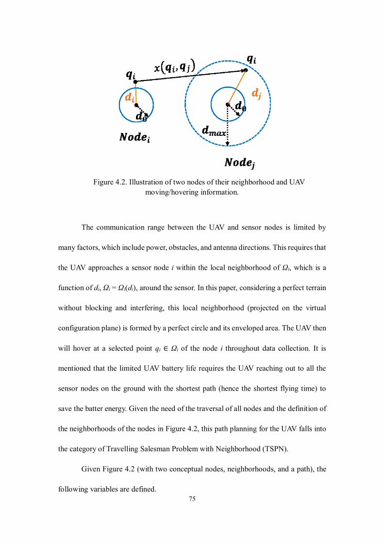
75
Figure 4.2. Illustration of two nodes of their neighborhood and UAV
moving/hovering information.
The communication range between the UAV and sensor nodes is limited by
many factors, which include power, obstacles, and antenna directions. This requires that
the UAV approaches a sensor node i within the local neighborhood of Ωi, which is a
function of di, Ωi = Ωi(di), around the sensor. In this paper, considering a perfect terrain
without blocking and interfering, this local neighborhood (projected on the virtual
configuration plane) is formed by a perfect circle and its enveloped area. The UAV then
will hover at a selected point qi ∈ Ωi of the node i throughout data collection. It is
mentioned that the limited UAV battery life requires the UAV reaching out to all the
sensor nodes on the ground with the shortest path (hence the shortest flying time) to
save the batter energy. Given the need of the traversal of all nodes and the definition of
the neighborhoods of the nodes in Figure 4.2, this path planning for the UAV falls into
the category of Travelling Salesman Problem with Neighborhood (TSPN).
Given Figure 4.2 (with two conceptual nodes, neighborhoods, and a path), the
following variables are defined.

76
• qi ,qj: UAV’s hovering location (a coordinate vector) for the sensor node
i,j;
• ϵi,j: a binary variable that if there is any traveling path selected between
the locations of qi and qj (ϵi,j =1, the path is selected; otherwise, not
selected);
• x(qi, qj): the spatial Euclidean distance from flying between the UAV
hovering positions qi and qj corresponding to the node i and j,
respectively, given a deterministic sensor network topology: x(qi, qj) = ||
qi - qj||, and it is noted that x(qi, qj) = x(qj, qi).
To simplify the formulation, the major energy consumption activity of the UAV,
which are the forward-moving and hovering modes driven by the motors, are
considered. Other energy costs, including imaging, networking, and others are ignored.
4.3.2 Communication Range with Data Loss
Interference and packet loss is a common issue in WSN and has been well
studied in the past [130-132]. Integrating a gateway device with a UAV makes the radio
environment more complicated. The first reason is that the UAV communicates with its
ground station using different wireless protocols than the WSN in the ground. It is
common that the UAV with an imaging payload needs a high-power and high-
throughput wireless protocol to send real-time video feeds back to the ground station,
while the wireless communication for the WSN is low-power due to its low energy
consumption requirements (hence low-power wireless protocols are often used, e.g.
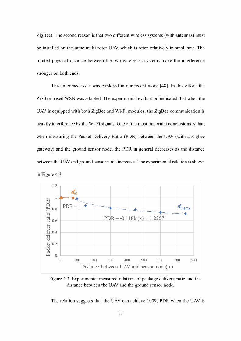
77
ZigBee). The second reason is that two different wireless systems (with antennas) must
be installed on the same multi-rotor UAV, which is often relatively in small size. The
limited physical distance between the two wirelesses systems make the interference
stronger on both ends.
This inference issue was explored in our recent work [48]. In this effort, the
ZigBee-based WSN was adopted. The experimental evaluation indicated that when the
UAV is equipped with both ZigBee and Wi-Fi modules, the ZigBee communication is
heavily interference by the Wi-Fi signals. One of the most important conclusions is that,
when measuring the Packet Delivery Ratio (PDR) between the UAV (with a Zigbee
gateway) and the ground sensor node, the PDR in general decreases as the distance
between the UAV and ground sensor node increases. The experimental relation is shown
in Figure 4.3.
Figure 4.3. Experimental measured relations of package delivery ratio and the
distance between the UAV and the ground sensor node.
The relation suggests that the UAV can achieve 100% PDR when the UAV is
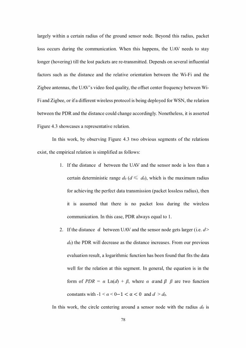
78
largely within a certain radius of the ground sensor node. Beyond this radius, packet
loss occurs during the communication. When this happens, the UAV needs to stay
longer (hovering) till the lost packets are re-transmitted. Depends on several influential
factors such as the distance and the relative orientation between the Wi-Fi and the
Zigbee antennas, the UAV’s video feed quality, the offset center frequency between Wi-
Fi and Zigbee, or if a different wireless protocol is being deployed for WSN, the relation
between the PDR and the distance could change accordingly. Nonetheless, it is asserted
Figure 4.3 showcases a representative relation.
In this work, by observing Figure 4.3 two obvious segments of the relations
exist, the empirical relation is simplified as follows:
1. If the distance 𝑑 between the UAV and the sensor node is less than a
certain deterministic range d0 (d ≤ d0), which is the maximum radius
for achieving the perfect data transmission (packet lossless radius), then
it is assumed that there is no packet loss during the wireless
communication. In this case, PDR always equal to 1.
2. If the distance 𝑑 between UAV and the sensor node gets larger (i.e. d >
d0) the PDR will decrease as the distance increases. From our previous
evaluation result, a logarithmic function has been found that fits the data
well for the relation at this segment. In general, the equation is in the
form of PDR = α Ln(d) + β, where α 𝛼 and 𝛽 β are two function
constants with -1 < α < 0−1 < α < 0 and d > d0.
In this work, the circle centering around a sensor node with the radius d0 is
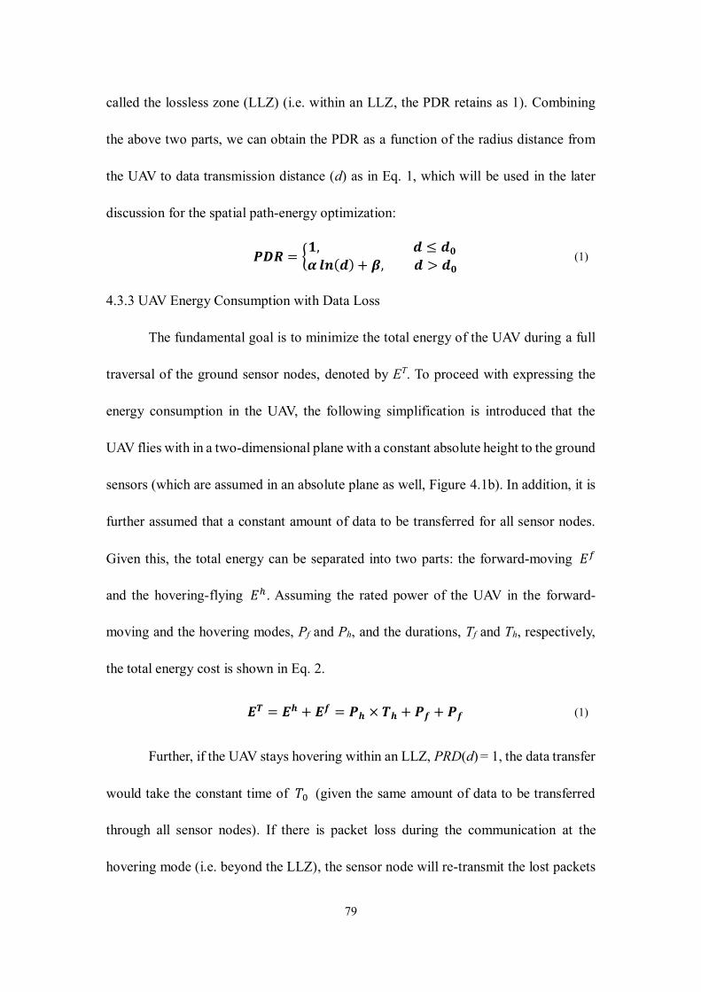
79
called the lossless zone (LLZ) (i.e. within an LLZ, the PDR retains as 1). Combining
the above two parts, we can obtain the PDR as a function of the radius distance from
the UAV to data transmission distance (d) as in Eq. 1, which will be used in the later
discussion for the spatial path-energy optimization:
𝑷𝑫𝑹 = {𝟏, 𝒅 ≤ 𝒅𝟎𝜶 𝒍𝒏(𝒅) + 𝜷, 𝒅 > 𝒅𝟎
(1)
4.3.3 UAV Energy Consumption with Data Loss
The fundamental goal is to minimize the total energy of the UAV during a full
traversal of the ground sensor nodes, denoted by ET. To proceed with expressing the
energy consumption in the UAV, the following simplification is introduced that the
UAV flies with in a two-dimensional plane with a constant absolute height to the ground
sensors (which are assumed in an absolute plane as well, Figure 4.1b). In addition, it is
further assumed that a constant amount of data to be transferred for all sensor nodes.
Given this, the total energy can be separated into two parts: the forward-moving 𝐸𝑓
and the hovering-flying 𝐸ℎ. Assuming the rated power of the UAV in the forward-
moving and the hovering modes, Pf and Ph, and the durations, Tf and Th, respectively,
the total energy cost is shown in Eq. 2.
𝑬𝑻 = 𝑬𝒉 + 𝑬𝒇 = 𝑷𝒉 × 𝑻𝒉 + 𝑷𝒇 + 𝑷𝒇 (1)
Further, if the UAV stays hovering within an LLZ, PRD(d) = 1, the data transfer
would take the constant time of 𝑇0 (given the same amount of data to be transferred
through all sensor nodes). If there is packet loss during the communication at the
hovering mode (i.e. beyond the LLZ), the sensor node will re-transmit the lost packets
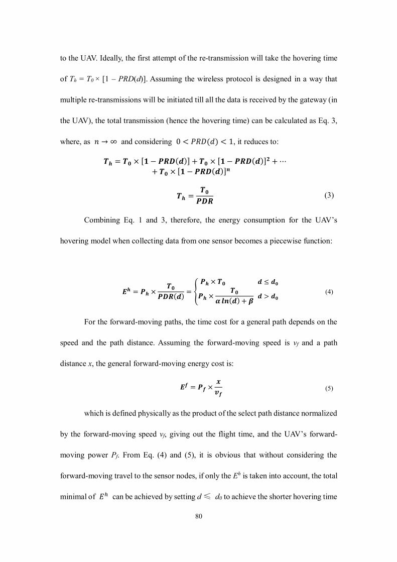
80
to the UAV. Ideally, the first attempt of the re-transmission will take the hovering time
of Th = T0 × [1 – PRD(d)]. Assuming the wireless protocol is designed in a way that
multiple re-transmissions will be initiated till all the data is received by the gateway (in
the UAV), the total transmission (hence the hovering time) can be calculated as Eq. 3,
where, as 𝑛 → ∞ and considering 0 < 𝑃𝑅𝐷(𝑑) < 1, it reduces to:
𝑻𝒉 = 𝑻𝟎 × [𝟏 − 𝑷𝑹𝑫(𝒅)] + 𝑻𝟎 × [𝟏 − 𝑷𝑹𝑫(𝒅)]
𝟐 +⋯
+ 𝑻𝟎 × [𝟏 − 𝑷𝑹𝑫(𝒅)]𝒏
𝑻𝒉 =𝑻𝟎𝑷𝑫𝑹
(3)
Combining Eq. 1 and 3, therefore, the energy consumption for the UAV’s
hovering model when collecting data from one sensor becomes a piecewise function:
𝑬𝒉 = 𝑷𝒉 ×𝑻𝟎
𝑷𝑫𝑹(𝒅)= {
𝑷𝒉 × 𝑻𝟎 𝒅 ≤ 𝒅𝟎
𝑷𝒉 ×𝑻𝟎
𝜶 𝒍𝒏(𝒅) + 𝜷 𝒅 > 𝒅𝟎
(4)
For the forward-moving paths, the time cost for a general path depends on the
speed and the path distance. Assuming the forward-moving speed is vf and a path
distance x, the general forward-moving energy cost is:
𝑬𝒇 = 𝑷𝒇 ×𝒙
𝒗𝒇 (5)
which is defined physically as the product of the select path distance normalized
by the forward-moving speed vf, giving out the flight time, and the UAV’s forward-
moving power Pf. From Eq. (4) and (5), it is obvious that without considering the
forward-moving travel to the sensor nodes, if only the Eh is taken into account, the total
minimal of 𝐸ℎ can be achieved by setting d ≤ d0 to achieve the shorter hovering time
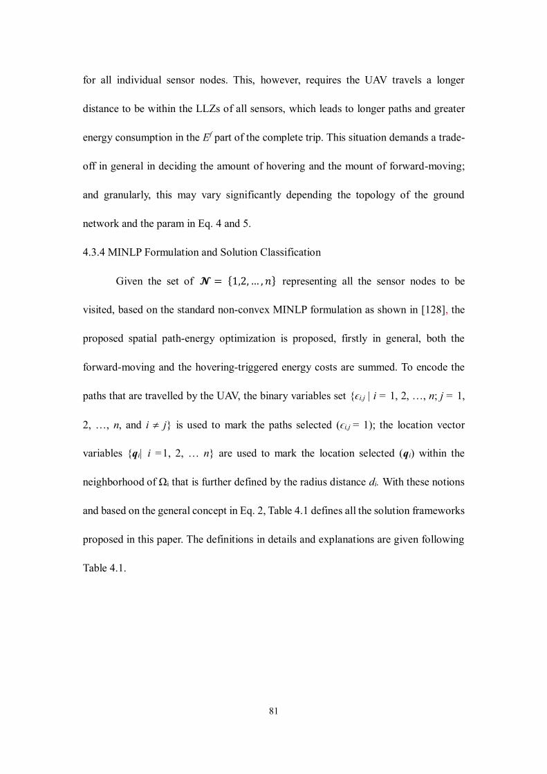
81
for all individual sensor nodes. This, however, requires the UAV travels a longer
distance to be within the LLZs of all sensors, which leads to longer paths and greater
energy consumption in the Ef part of the complete trip. This situation demands a trade-
off in general in deciding the amount of hovering and the mount of forward-moving;
and granularly, this may vary significantly depending the topology of the ground
network and the param in Eq. 4 and 5.
4.3.4 MINLP Formulation and Solution Classification
Given the set of 𝓝 = {1,2,… , 𝑛} representing all the sensor nodes to be
visited, based on the standard non-convex MINLP formulation as shown in [128], the
proposed spatial path-energy optimization is proposed, firstly in general, both the
forward-moving and the hovering-triggered energy costs are summed. To encode the
paths that are travelled by the UAV, the binary variables set {ϵi,j | i = 1, 2, …, n; j = 1,
2, …, n, and i j} is used to mark the paths selected (ϵi,j = 1); the location vector
variables {qi| i =1, 2, … n} are used to mark the location selected (qi) within the
neighborhood of Ωi that is further defined by the radius distance di. With these notions
and based on the general concept in Eq. 2, Table 4.1 defines all the solution frameworks
proposed in this paper. The definitions in details and explanations are given following
Table 4.1.
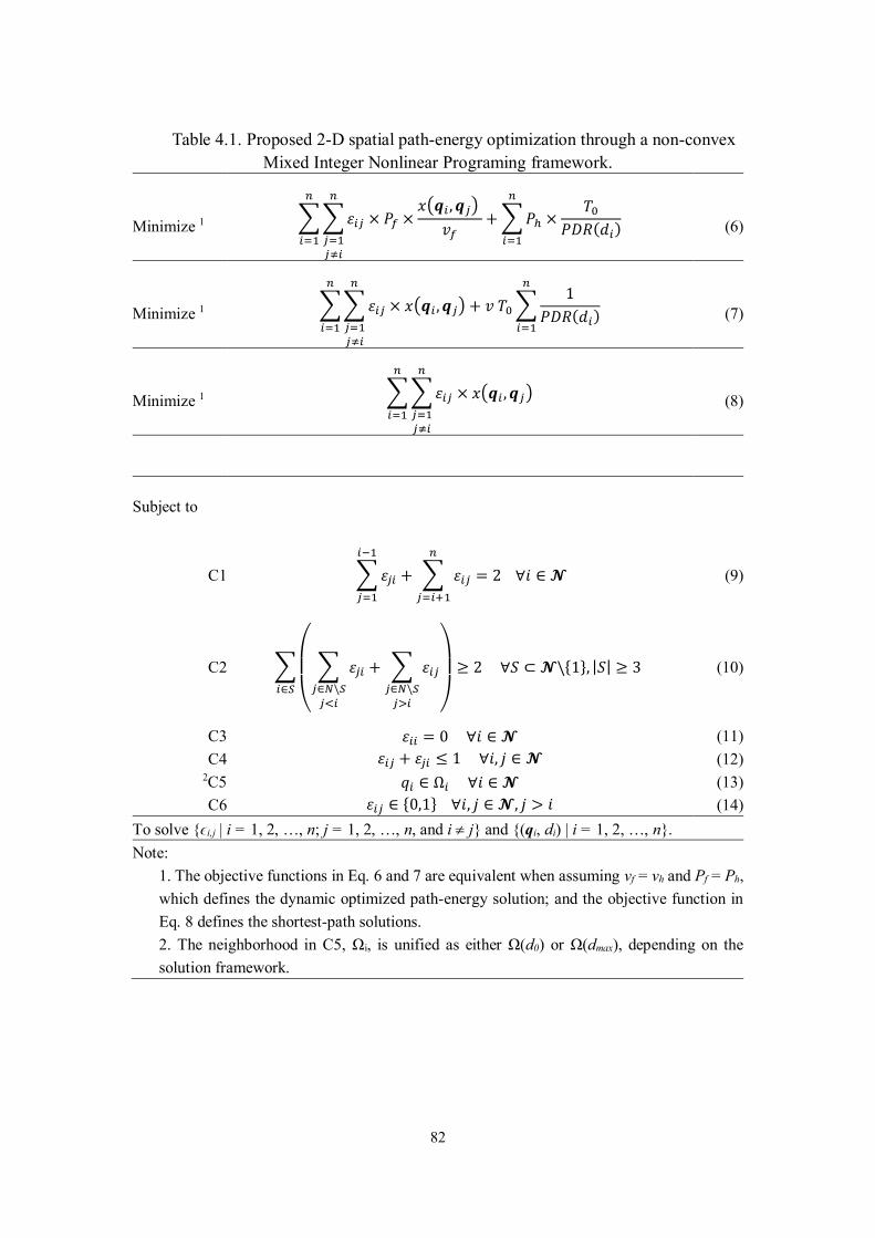
82
Table 4.1. Proposed 2-D spatial path-energy optimization through a non-convex
Mixed Integer Nonlinear Programing framework.
Minimize 1 ∑∑𝜀𝑖𝑗 × 𝑃𝑓 ×
𝑥(𝒒𝑖 , 𝒒𝑗)
𝑣𝑓
𝑛
𝑗=1𝑗≠𝑖
𝑛
𝑖=1
+∑𝑃ℎ ×𝑇0
𝑃𝐷𝑅(𝑑𝑖)
𝑛
𝑖=1
(6)
Minimize 1 ∑∑𝜀𝑖𝑗 × 𝑥(𝒒𝑖 , 𝒒𝑗)
𝑛
𝑗=1𝑗≠𝑖
𝑛
𝑖=1
+ 𝑣 𝑇0∑1
𝑃𝐷𝑅(𝑑𝑖)
𝑛
𝑖=1
(7)
Minimize 1 ∑∑𝜀𝑖𝑗 × 𝑥(𝒒𝑖 , 𝒒𝑗)
𝑛
𝑗=1𝑗≠𝑖
𝑛
𝑖=1
(8)
Subject to
C1 ∑𝜀𝑗𝑖
𝑖−1
𝑗=1
+ ∑ 𝜀𝑖𝑗
𝑛
𝑗=𝑖+1
= 2 ∀𝑖 ∈ 𝓝 (9)
C2 ∑
(
∑ 𝜀𝑗𝑖𝑗∈𝑁\𝑆𝑗<𝑖
+ ∑ 𝜀𝑖𝑗𝑗∈𝑁\𝑆𝑗>𝑖 )
𝑖∈𝑆
≥ 2 ∀𝑆 ⊂ 𝓝\{1}, |𝑆| ≥ 3 (10)
C3 𝜀𝑖𝑖 = 0 ∀𝑖 ∈ 𝓝 (11)
C4 𝜀𝑖𝑗 + 𝜀𝑗𝑖 ≤ 1 ∀𝑖, 𝑗 ∈ 𝓝 (12) 2C5 𝑞𝑖 ∈ Ω𝑖 ∀𝑖 ∈ 𝓝 (13)
C6 𝜀𝑖𝑗 ∈ {0,1} ∀𝑖, 𝑗 ∈ 𝓝, 𝑗 > 𝑖 (14)
To solve {ϵi,j | i = 1, 2, …, n; j = 1, 2, …, n, and i j} and {(qi, di) | i = 1, 2, …, n}.
Note:
1. The objective functions in Eq. 6 and 7 are equivalent when assuming vf = vh and Pf = Ph,
which defines the dynamic optimized path-energy solution; and the objective function in
Eq. 8 defines the shortest-path solutions.
2. The neighborhood in C5, Ωi, is unified as either Ω(d0) or Ω(dmax), depending on the
solution framework.
83
First, a novel and generalized objective function is proposed in Eq. 6. This
objective function comprises two summation terms with the first being the total
summed forward-moving energy cost by traveling to all the local neighborhoods
following a selected path scenario, and the second term being the total summed
hovering induced energy cost for which the hovering time depends on the
communication packet delivery rate function PDR(di). Eqs. 9 to 14 further define the
constraints (C1 to C6) that provide restriction in searching for the optimum of ϵi,j’s, qi’s,
and the associated di’s. Table 4.1 summarizes the completed expressions for executing
the nonconvex MINLP optimization framework.
Among the constraints C1 to C6, the constraint C1 ensures that each node is
visited once and only once by the UAV. C2 eliminate any sub-tour by forcing the
number of active edges departing from any subgraph induced by a subset of the vertices
with cardinality at least 2 to be at least equal to 1 [128]. Constrains C3 and C4 prevent
the node from connecting to itself, as well as from two nodes forming a circle. C5
defines the neighborhood for each sensor node (a critical condition to be elaborated
later); and C6 makes sure 𝜀𝑖𝑗 is binary.
Several parametric assumptions can be made for achieving the simplicity yet
without losing the generality:
1. The unit power of the UAV remains a constant during the hovering and
forward-moving modes; hence, Pf = Ph = P;
2. The speed of the UAV remains a constant during forward-moving
modes; hence, vf = v;
84
In reality, one may assume that the hovering power (or speed) is only a fraction
of the forward-moving power (or speed), namely vh = γ1 vf or Pf =γ2 Ph, respectively;
and similar simplification can be achieved as well. These two parametric assumptions
will simplify the expression of the resulting objective function (Eq. 7) with the same
constraints previously.
Given the objective function in Eq. 6 or 7, it is noted that this differs from the
standard objective function in the literature [128]. In a standard TSPN problem, the
objective function is simply defined as the cumulative summation of all selected paths
between the selected locations (i.e. the first term in Eq. 7). The Euclidian distance x(qi,
qj) hides a pivotal variable – the radius distance between the sensor nodes and the UAV,
correspondingly di and dj, respectively; as shown in Figure 4.2, the variable di and dj
values modify nonlinearly the Euclidian distance x(qi, qj). Herein, to achieve the
optimal (minimized) path-energy cost, the energy cost due to the hovering and data
collection is added in addition to the forward-moving traversal of all sensor
neighborhoods. As qualitatively implied earlier and further evidenced in Eq. 6 or 7,
there exists a dynamic balance between minimizing the shortest paths only hence less
in forward-moving traveling energy cost (the first term in Eq. 6 or 7;) and minimizing
the hovering energy cost (the second term in Eq. 6 or 7).
In addition, it is recognized that in a standard TSPN problem, the neighborhood
for each target location (Ωi) is user-defined with a fixed local area has been outlined
(considering other conditions). For the UAV serving as a gateway to receive data from
the ground sensors, there are no such pre-defined neighborhoods. Based on the PDR
85
function in Figure 4.3, two critical neighborhoods are recognized: the neighborhoods
defined by the aforementioned LLZ radius d0, defined by Ω(d0); and further, by
assuming a maximal packet loss radius (based on an empirical justification) dmax, at
which the packet delivery rate is as the smallest as to maintain an effective
communication link, a maximal packet-loss neighborhood Ω(dmax) is defined. In the
meantime, one can practically define that these neighborhoods do not overlap between
nodes.
With the insight into the possible tradeoff between the forward-moving
traveling energy cost and the hovering energy cost, and the flexibility in defining the
local neighborhoods, two possible lower-bound solutions are derived. First, one seeks
to minimize the forward-moving traveling energy cost (Eq. 8), namely the shortest-path
solution; then by setting the local neighborhoods, two bound solutions are obtained:
1. Set Ωi = Ω(d0), namely all local neighborhoods assume the same circular
local region defined by the LLZ radius d0. By taking this neighborhood
setting, for all sensor nodes, the data communication is lossless hence
the hovering time is less; hence the resulting solution is called Lossless
Shortest-path (LL-SP) solution in this paper. This solution tends to give
rise to less hovering energy cost.
2. Set Ωi = Ω(dmax), namely all local neighborhoods assume the same
circular local region defined by the maximal-loss radius dmax. By taking
this neighborhood setting, for all sensor nodes, the data communication
within this neighborhood possibly encounters maximal loss. However,
86
the total traversal paths across all sensor nodes may be smaller than the
solution above (due to the larger neighborhood size); therefore, the total
energy cost may still poise to be a lower-bound. This resulting solution
is called Maximal-loss Shortest-path (ML-SP) solution in this paper.
This solution tends to give rise to less forward-moving energy cost.
To carry out the originally proposed spatial path-energy optimization expressed
in the objective function in Eq. 7 and to have a fair comparison with the above two
shortest-path solutions, the local subdomains Ωi is set equal to Ω(dmax) as well.
However, as expressed earlier, this solution emphasizes a dynamic balance through
minimizing the total energy cost including both the forward-moving and hovering of
the UAV. This solution is called dynamically minimized path-energy (DM-PE) solution.
If all the three solution frameworks are solved through the MINLP procedure,
denoted by {qi*, di
*, ϵi,j*| i =1, 2, …, n; j = 1, 2, …, n, j ≠ i}, the total energy (subject
to multiplying the force constant P/v) can be inserted in the objective functions. Noted
that when using Eq. 8, the constant energy term due to the hovering needs to be added
back. This uniform total ‘energy’ function (subject to a constant multiplier P/v) is shown
below in Eq. 15. It is noted that in this equation, the optimized radius distances (di*,)
for all sensor nodes are explicitly expressed in the optimized UAV locations qi*’s.
𝑬𝑻 =∑∑𝜺𝒊𝒋 × 𝒙(𝒒𝒊
∗ [𝒅𝒊∗], 𝒒𝒋
∗[𝒅𝒋∗])
𝒏
𝒋=𝟏𝒋≠𝒊
𝒏
𝒊=𝟏
+ 𝒗 𝑻𝟎∑𝟏
𝑷𝑫𝑹(𝒅𝒊∗)
𝒏
𝒊=𝟏
(15)
With the three solution frameworks, the resulting total energy quantities are
termed 𝐸𝐿𝐿−𝑆𝑃𝑇 , 𝐸𝑀𝐿−𝑆𝑃
𝑇 , and 𝐸𝐷𝑀−𝑃𝐸𝑇 , respectively.
87
With the three total energy costs, and given the objective is to find the minimum
of the total energy cost, it is desirable to rank them without numerical evaluation.
However, due to the complexity in the nonlinearity in defining the objective function
and further due to the unforeseen possibility of the spatial topology of the ground sensor
network, it is unfortunate that no deterministic ranking is possible. The least insight as
previously pointed out is that either the LL-SP or the ML-SP solution may offer a lower-
bound energy cost.
From an optimization, theoretic point of view, the second term in Eq. 7 acts like
a regularization term. In addition, the second term is necessary in calculating the total
energy, even the shortest-path solutions are used. From this insight, the product term v
T0, denoted by λ = v T0, which physically equivalent to the flight distance if the UAV
flies instead of hovering given a speed of v and a time of T0 (the data transmission time).
The summation term (∑1
𝑃𝐷𝑅(𝑑𝑖∗)
𝑛𝑖=1 ) hence acts as the ‘penalty’ function, which imposes
additional ‘path’ cost to the total forward-moving traversal energy cost. This λ, termed
the path-energy control parameter, therefore is worthy of parametric investigation in
accordance with its physical meaning. Comprehensive numerical evaluation and the
advantage of the proposed DM-PE solution are offered below.
4.4 Implementation and Numerical Evaluation
4.4.1 Optimization Package and Implementation
We use Julia Programming Language as our programming environment, and
Juniper [133], a nonlinear branch-and-bound solver for our calculation. Juniper (Jump
Non-linear Integer Program solver) is a solver for Mixed Integer Non-Linear Programs
88
(MINLPs) written in Julia. Juniper solves these kinds of problems using an NLP solver
and then branch and bound. If the NLP solver isn't global optimal then Juniper is a
heuristic.
4.4.2 Simple Examples
Following the previously defined optimization schemes in Table 4.1, the goal
here is to compare the differences of the solution using three different optimization
schemes and compare the total energy costs. First, the following network param are
selected listed in Table 4.2 (for 𝛼, 𝛽, 𝑑0 and 𝑑𝑚𝑎𝑥).
Table 4.2 Numerical value of the network param.
Parameter Value
𝛼 -0.118
𝛽 1.225
𝑑0 50
𝑑𝑚𝑎𝑥 500
A simple 10-node instance is devised in this experiment. The LLZ radius 𝑑0
equals to 50 m, and the practical maximum data transmission range dmax is 500 m. Using
this setup, the three optimization schemes (LL-SP, ML-SP, and DM-PE) are obtained.
The results with the achieved traveling graphs are shown in Figure 4.4 and Table 4.3.
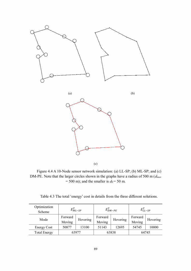
89
(a) (b)
(c)
Figure 4.4 A 10-Node sensor network simulation: (a) LL-SP; (b) ML-SP; and (c)
DM-PE. Note that the larger circles shown in the graphs have a radius of 500 m (dmax
= 500 m); and the smaller is d0 = 50 m.
Table 4.3 The total ‘energy’ cost in details from the three different solutions.
Optimization
Scheme 𝐸𝑀𝐿−𝑆𝑃𝑇 𝐸𝐷𝑀−𝑃𝐸
𝑇 𝐸𝐿𝐿−𝑆𝑃𝑇
Mode Forward
Moving Hovering
Forward
Moving Hovering
Forward
Moving Hovering
Energy Cost 50877 13100 51143 12695 54745 10000
Total Energy 63977 63838 64745
90
The different resulting traveling paths clearly show that the results are much
different. The proposed DM-PE optimization scheme, which show in Figure 4.4(c),
suggests that the UAV should neither use the dmax nor d0 as neighborhood radius and
using a traditional TSPN solution. The UAV should hover between 𝑑0 and 𝑑𝑚𝑎𝑥. The
location is determined by the parameter values of 𝛼, 𝛽, 𝑑0, 𝑣 and 𝑇0. From equation
1 we know that 𝛼, 𝛽 and 𝑑0 are related to wireless communication hardware and
cannot be changed once the hardware is implemented. The product of 𝑣 and 𝑇0 is
another important factor to determine where the UAV should hover: The larger the
product, the more energy is consumed during the hovering states, thus we want the UAV
fly closer to the node, in extreme case, our approach will have the same result as the
Lossless approach. On the contrary, if the product of 𝑣 and 𝑇0 is small, we want less
UAV travel distance and hover further from the node. In extreme case, our approach
will have the same result as the Shortest distance approach.
4.4.3 Large-scale Examples
To maximize the similarity between our simulation and the real applications, we
generate 173 nodes located in a 20000 square meter area. Each node is at least 100 m
away from the nearest neighbor to make sure their neighborhood does not overlap.
From the 173 nodes set, we randomly pick 10, 15, 20 … nodes as our node map to run
the simulation. The following tables (Table 4.4 to Table 4.6) show the total energy of
different nodes and approaches. In each table, the left column is the total number of the
nodes for each simulation instance; each row shows the total “energy” for different
approaches, the numerical value “energy” represents the sum of Euclidean distance and
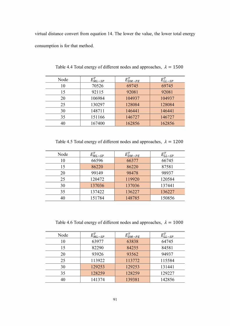
91
virtual distance convert from equation 14. The lower the value, the lower total energy
consumption is for that method.
Table 4.4 Total energy of different nodes and approaches, 𝜆 = 1500
Node 𝐸𝑀𝐿−𝑆𝑃𝑇 𝐸𝐷𝑀−𝑃𝐸
𝑇 𝐸𝐿𝐿−𝑆𝑃𝑇
10 70526 69745 69745
15 92115 92081 92081
20 106984 104937 104937
25 130297 128084 128084
30 148711 146441 146441
35 151166 146727 146727
40 167400 162856 162856
Table 4.5 Total energy of different nodes and approaches, 𝜆 = 1200
Node 𝐸𝑀𝐿−𝑆𝑃𝑇 𝐸𝐷𝑀−𝑃𝐸
𝑇 𝐸𝐿𝐿−𝑆𝑃𝑇
10 66596 66377 66745
15 86220 86220 87581
20 99149 98478 98937
25 120472 119920 120584
30 137036 137036 137441
35 137422 136227 136227
40 151784 148785 150856
Table 4.6 Total energy of different nodes and approaches, 𝜆 = 1000
Node 𝐸𝑀𝐿−𝑆𝑃𝑇 𝐸𝐷𝑀−𝑃𝐸
𝑇 𝐸𝐿𝐿−𝑆𝑃𝑇
10 63977 63838 64745
15 82290 84255 84581
20 93926 93562 94937
25 113922 113772 115584
30 129253 129253 131441
35 128259 128259 129227
40 141374 139381 142856
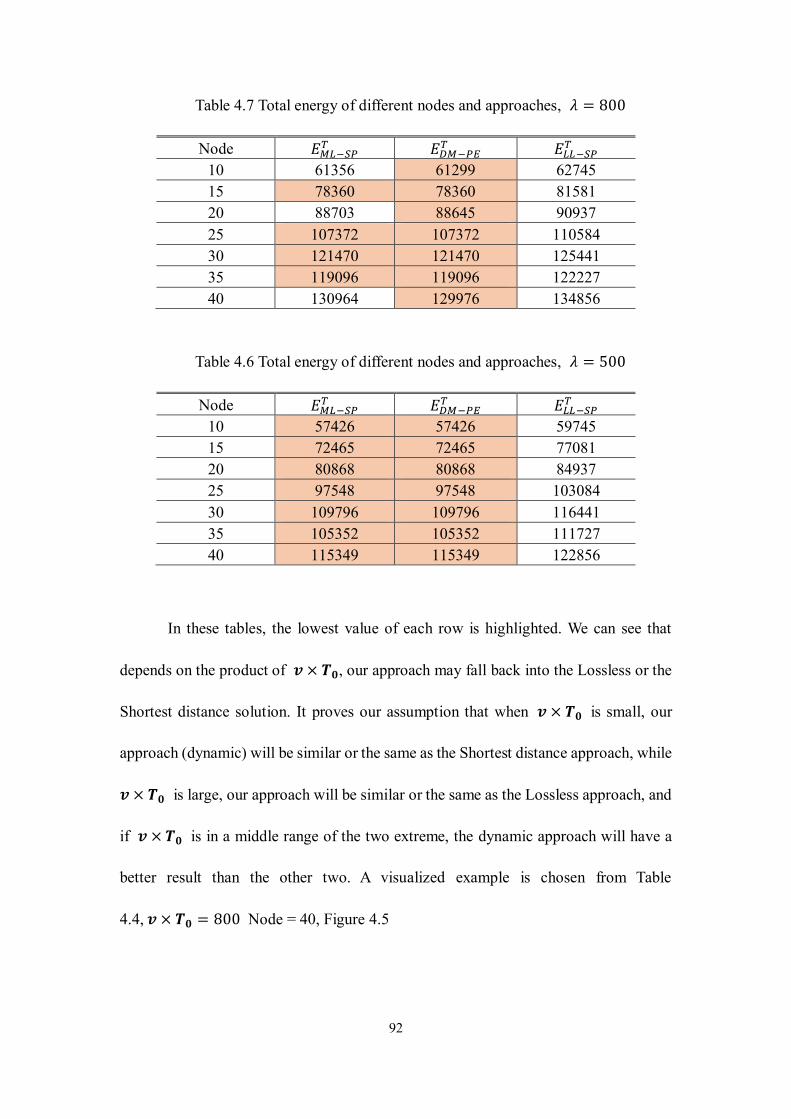
92
Table 4.7 Total energy of different nodes and approaches, 𝜆 = 800
Node 𝐸𝑀𝐿−𝑆𝑃𝑇 𝐸𝐷𝑀−𝑃𝐸
𝑇 𝐸𝐿𝐿−𝑆𝑃𝑇
10 61356 61299 62745
15 78360 78360 81581
20 88703 88645 90937
25 107372 107372 110584
30 121470 121470 125441
35 119096 119096 122227
40 130964 129976 134856
Table 4.6 Total energy of different nodes and approaches, 𝜆 = 500
Node 𝐸𝑀𝐿−𝑆𝑃𝑇 𝐸𝐷𝑀−𝑃𝐸
𝑇 𝐸𝐿𝐿−𝑆𝑃𝑇
10 57426 57426 59745
15 72465 72465 77081
20 80868 80868 84937
25 97548 97548 103084
30 109796 109796 116441
35 105352 105352 111727
40 115349 115349 122856
In these tables, the lowest value of each row is highlighted. We can see that
depends on the product of 𝒗 × 𝑻𝟎, our approach may fall back into the Lossless or the
Shortest distance solution. It proves our assumption that when 𝒗 × 𝑻𝟎 is small, our
approach (dynamic) will be similar or the same as the Shortest distance approach, while
𝒗 × 𝑻𝟎 is large, our approach will be similar or the same as the Lossless approach, and
if 𝒗 × 𝑻𝟎 is in a middle range of the two extreme, the dynamic approach will have a
better result than the other two. A visualized example is chosen from Table
4.4, 𝒗 × 𝑻𝟎 = 800 Node = 40, Figure 4.5
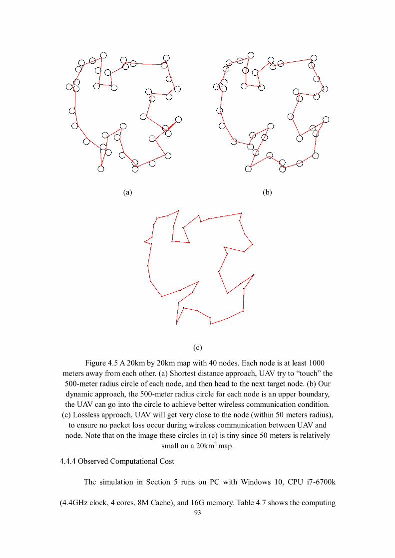
93
(a) (b)
(c)
Figure 4.5 A 20km by 20km map with 40 nodes. Each node is at least 1000
meters away from each other. (a) Shortest distance approach, UAV try to “touch” the
500-meter radius circle of each node, and then head to the next target node. (b) Our
dynamic approach, the 500-meter radius circle for each node is an upper boundary,
the UAV can go into the circle to achieve better wireless communication condition.
(c) Lossless approach, UAV will get very close to the node (within 50 meters radius),
to ensure no packet loss occur during wireless communication between UAV and
node. Note that on the image these circles in (c) is tiny since 50 meters is relatively
small on a 20km2 map.
4.4.4 Observed Computational Cost
The simulation in Section 5 runs on PC with Windows 10, CPU i7-6700k
(4.4GHz clock, 4 cores, 8M Cache), and 16G memory. Table 4.7 shows the computing
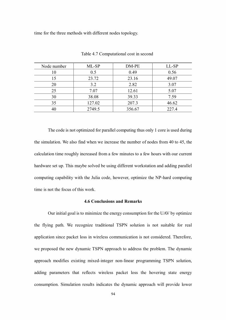
94
time for the three methods with different nodes topology.
Table 4.7 Computational cost in second
Node number ML-SP DM-PE LL-SP
10 0.5 0.49 0.56
15 23.72 23.16 49.07
20 3.2 2.82 3.07
25 7.07 12.61 5.07
30 38.08 39.33 7.59
35 127.02 207.3 46.62
40 2749.5 356.67 227.4
The code is not optimized for parallel computing thus only 1 core is used during
the simulation. We also find when we increase the number of nodes from 40 to 45, the
calculation time roughly increased from a few minutes to a few hours with our current
hardware set up. This maybe solved be using different workstation and adding parallel
computing capability with the Julia code, however, optimize the NP-hard computing
time is not the focus of this work.
4.6 Conclusions and Remarks
Our initial goal is to minimize the energy consumption for the UAV by optimize
the flying path. We recognize traditional TSPN solution is not suitable for real
application since packet loss in wireless communication is not considered. Therefore,
we proposed the new dynamic TSPN approach to address the problem. The dynamic
approach modifies existing mixed-integer non-linear programming TSPN solution,
adding parameters that reflects wireless packet loss the hovering state energy
consumption. Simulation results indicates the dynamic approach will provide lower
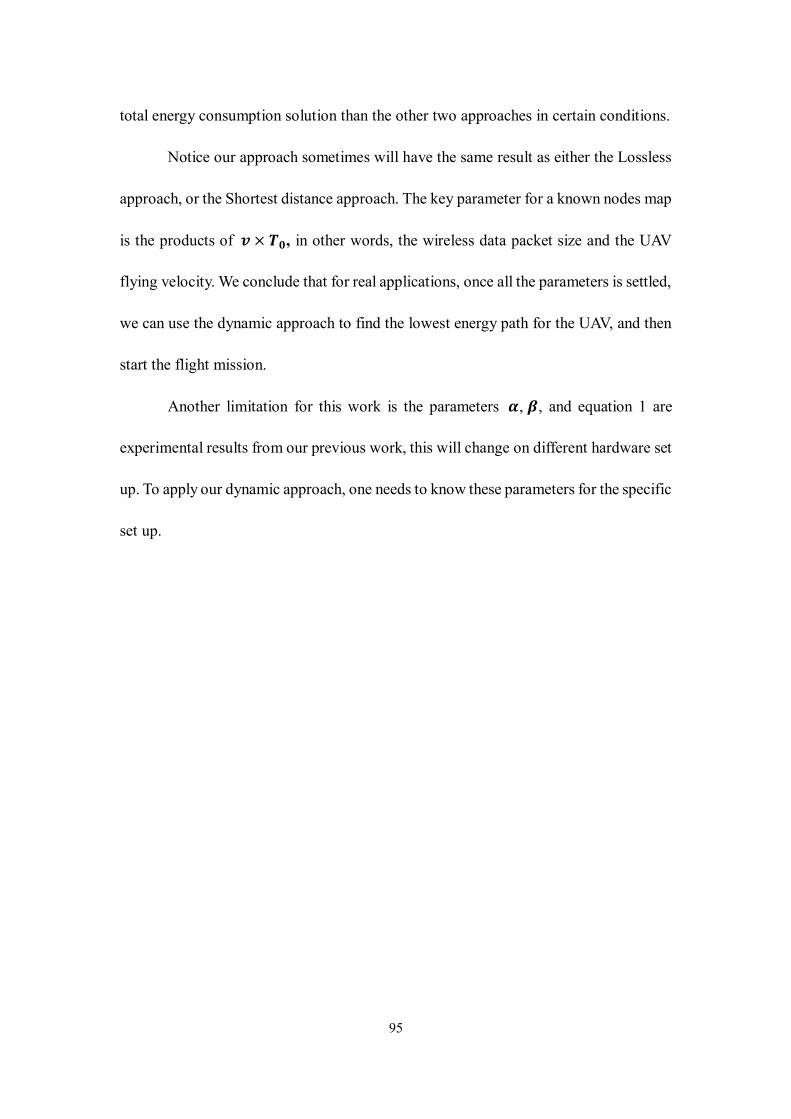
95
total energy consumption solution than the other two approaches in certain conditions.
Notice our approach sometimes will have the same result as either the Lossless
approach, or the Shortest distance approach. The key parameter for a known nodes map
is the products of 𝒗 × 𝑻𝟎, in other words, the wireless data packet size and the UAV
flying velocity. We conclude that for real applications, once all the parameters is settled,
we can use the dynamic approach to find the lowest energy path for the UAV, and then
start the flight mission.
Another limitation for this work is the parameters 𝜶 , 𝜷 , and equation 1 are
experimental results from our previous work, this will change on different hardware set
up. To apply our dynamic approach, one needs to know these parameters for the specific
set up.
96
CHAPTER 5
CONCLUSION AND FUTURE WORK
5.1 Conclusion
In this dissertation, a novel aerial-ground wireless sensing network (AG-WSN)
that aims to transform a number of critical geospatial sensing and monitoring practices,
such as precision agriculture, civil infrastructure protection, and disaster response, is
developed. To achieve maximal energy efficiency, three research problems are
concerned in this dissertation.
First, a radio-frequency (RF) wake-up mechanism is investigated for aerial
activation of ground sensors using a UAV platform. In this section, we reviewed and
compared different wake-up mechanism for WSN and chose active radio frequency
based wake-up method and implemented physically. We find that the RF-based out-
band wake-up mechanism can save a great deal of energy compared with the other two
solutions (the infrared wake-up and the default duty-cycle methods).The results show
that the RF-based wake-up mechanism can potentially save more than 98.4% of the
energy that the traditional duty-cycle method would otherwise consume, and 96.8% if
an infrared-receiver method is used.
Based on this setup, the delay of wake-up is also studied by using high speed
camera. The results indicate with a variety of wake-up RF signal combination, the delay
is less than 80 milliseconds hence will not affect the overall opportunistic sensing
applications.
Second, the data transmission under wireless interference between the UAV and
97
ground WSN, specifically between Wi-Fi and ZigBee, is experimentally investigated.
It is observed that the relative position of the Wi-Fi and ZigBee antennas and the
distance between them are the two major factors that impact the communication. In the
long-range experiment, the ZigBee data transmission is tested as the range varies up to
800 meters (the line-of-sight distance). Defining the range with the packet delivery rate
of 99.8% as the ZigBee ‘comfort zone’, the effect of the ZigBee/Wi-Fi antenna distance
is further determined and recognized as a sensitive parameter. It is found that with a
few centimeters of increment in this distance, the comfort zone range can be improved
significantly. These results provide the guideline in designing the mixed
communication configuration in deploying the proposed aerial-ground sensing network
wherein Wi-Fi and ZigBee networking are both involved, especially when the ranges
of operating frequencies at both overlap. Besides that, finding of the relation between
Zigbee packet loss and distance provides an important parameter for the last part of the
dissertation research.
Last, this dissertation theoretically explores and develops an optimization
framework for UAV's aerial path planning when collecting ground-sensor data. We
recognize traditional TSPN solution is not suitable for real application since packet loss
in wireless communication is not considered. Therefore, we proposed the new Dynamic
TSPN approach to address the problem, which used an improved mixed-integer non-
linear programming approach. Simulation results indicates the Dynamic approach will
provide lower total energy consumption solution than the other two approaches in
certain conditions.
98
We find that the products of 𝒗 × 𝑻𝟎, in other words, the wireless data packet
size and the UAV flying velocity is a key parameter that may have impact the
optimization solution. Thus, we suggest for real application this value should be
determined carefully before each flight mission.
5.2 Future Work
There are several future tasks are identified through the dissertation.
1. The method to evaluate the energy consumption of wireless sensor node in this work
is at a higher level, which provides the number of days the sensor node can work
until it turns off. An alternative approach would be using high accuracy bench
digital meters, to provide real-time power consumption of the node, which can
further strength our assumptions that RF wake-up mechanism is at advantage of
other methods.
2. The experimental in Chapter 3 is based on the commercially available DJI drone
and hence is not a platform suitable for developments. The Wi-Fi parameter on that
platform is not in our control, thus we did not conduct experiments on how the Wi-
Fi video feed quality and the power level for both Wi-Fi and Zigbee radio will affect
the interference level. Further work can be done using a customizable UAV platform
with different Wi-Fi modules.
3. It is noted that Chapter 3 focuses on defining the concept of the aerial-ground
wireless sensing and investigating the network interference within such a novel
network, realistic structural response and environmental data are not analyzed. The
future efforts based on finding in this include the development of heterogeneous
99
sensing including low-speed environmental sensing (e.g. temperature and moisture
data at a rate of one data point per minute) and fast structural sensing (e.g.
acceleration data at a rate of 200 points per second), and the aerial real-time data
acquisition and computing. The subsequent investigation will include the
implementation of a decentralized sensing solution that is optimized for either a
single large-scale structure or a geospatially-large structure clusters in an urban
area. The implementation task further includes the edge-computing based data
processing and system identification towards fully real-time flying, sensing, and
delivering of structural health and condition assessment analytics.
4. Simulation in Chapter 5 is using Julia programming language, the code is not
optimized for parallel computing, which results running on a multi-core multi-
threads CPU cannot improve the computation time. One possible improvement
would be optimizing the coding for parallel computing.
5. The result on energy consumption indicate that across the different approach, the
total energy difference is not huge compare to their total value. This may lead to a
debate that whether it is worth of trying to compute for the optimization path since
it may cost more energy for compute than it saves. We believe this can be further
investigated by take the computing cost into consider and compare the energy cost
to the UAV flying energy.
6. Some parameter provides to run the simulation in Chapter 5 are based on the
experiments done in Chapter 4. Thus, it only provides one possible wireless packet
loss model. We suggest other researches could conduct more experiments with

100
different hardware setup to get different model of wireless packet loss relative to
distance. Then apply our dynamic approach to evaluate the energy consumption
results with our setup.
101
REFERENCES
[1] L. Ruiz-Garcia, L. Lunadei, P. Barreiro, and I. Robla, "A review of wireless
sensor technologies and applications in agriculture and food industry: state of
the art and current trends," Sensors, vol. 9, no. 6, pp. 4728-4750, 2009.
[2] The Economist. (2017). Superstructures. Available:
https://www.economist.com/node/17647603
[3] C. Pohl and J. L. Van Genderen, "Review article multisensor image fusion in
remote sensing: concepts, methods and applications," International Journal of
Remote Sensing, vol. 19, no. 5, pp. 823-854, 1998.
[4] A. Singh, "Review article digital change detection techniques using remotely-
sensed data," International Journal of Remote Sensing, vol. 10, no. 6, pp. 989-
1003, 1989.
[5] F. Y. Narvaez, G. Reina, M. Torres-Torriti, G. Kantor, and F. A. Cheein, "A
Survey of Ranging and Imaging Techniques for Precision Agriculture
Phenotyping," IEEE/ASME Transactions on Mechatronics, vol. 22, no. 6, pp.
2428-2439, 2017.
[6] I. Colomina and P. Molina, "Unmanned aerial systems for photogrammetry and
remote sensing: A review," ISPRS Journal of Photogrammetry and Remote
Sensing, vol. 92, pp. 79-97, 2014.
[7] C. Zhang and J. M. Kovacs, "The application of small unmanned aerial systems
for precision agriculture: a review," Precision Agriculture, vol. 13, no. 6, pp.
693-712, 2012.
[8] E. Kayacan, H. Ramon, and W. Saeys, "Robust trajectory tracking error model-
based predictive control for unmanned ground vehicles," IEEE/ASME
Transactions on Mechatronics, vol. 21, no. 2, pp. 806-814, 2016.
[9] A. Baggio, "Wireless sensor networks in precision agriculture," in ACM
Workshop on Real-World Wireless Sensor Networks (REALWSN 2005),
Stockholm, Sweden, 2005, pp. 1567-1576.
[10] X. Dong, M. C. Vuran, and S. Irmak, "Autonomous precision agriculture
through integration of wireless underground sensor networks with center pivot
irrigation systems," Ad Hoc Networks, vol. 11, no. 7, pp. 1975-1987, 9// 2013.
[11] N. Wang, N. Zhang, and M. Wang, "Wireless sensors in agriculture and food
industry—Recent development and future perspective," Computers and
Electronics in Agriculture, vol. 50, no. 1, pp. 1-14, 1// 2006.
[12] N. Dlodlo and J. Kalezhi, "The internet of things in agriculture for sustainable
rural development," in Emerging Trends in Networks and Computer
Communications (ETNCC), 2015 International Conference on, 2015, pp. 13-
18: IEEE.
[13] J. Ma, X. Zhou, S. Li, and Z. Li, "Connecting agriculture to the internet of things
through sensor networks," in Internet of Things (iThings/CPSCom), 2011
International Conference on and 4th International Conference on Cyber,
Physical and Social Computing, 2011, pp. 184-187: IEEE.
[14] J. P. Lynch and K. J. Loh, "A summary review of wireless sensors and sensor
102
networks for structural health monitoring," Shock and Vibration Digest, vol. 38,
no. 2, pp. 91-130, 2006.
[15] Y. Gao, B. Spencer, and M. Ruiz‐Sandoval, "Distributed computing strategy for
structural health monitoring," Structural Control and Health Monitoring, vol.
13, no. 1, pp. 488-507, 2006.
[16] T. Nagayama and B. F. Spencer Jr, "Structural health monitoring using smart
sensors," Newmark Structural Engineering Laboratory. University of Illinois at
Urbana-Champaign.1940-9826, 2007.
[17] Y. Wang, J. P. Lynch, and K. H. Law, "A wireless structural health monitoring
system with multithreaded sensing devices: design and validation," Structure
and Infrastructure Engineering, vol. 3, no. 2, pp. 103-120, 2007.
[18] G. Morgenthal and N. Hallermann, "Quality assessment of unmanned aerial
vehicle (UAV) based visual inspection of structures," Advances in Structural
Engineering, vol. 17, no. 3, pp. 289-302, 2014.
[19] N. Metni and T. Hamel, "A UAV for bridge inspection: Visual servoing control
law with orientation limits," Automation in Construction, vol. 17, no. 1, pp. 3-
10, 2007.
[20] C. M. Yeum and S. J. Dyke, "Vision‐based automated crack detection for bridge
inspection," Computer‐Aided Civil and Infrastructure Engineering, vol. 30, no.
10, pp. 759-770, 2015.
[21] H. Yoon and B. F. Spencer Jr, "Enabling smart city resilience: Post-disaster
response and structural health monitoring," Newmark Structural Engineering
Laboratory. University of Illinois at Urbana-Champaign.1940-9826, 2016.
[22] M. Collotta, L. Gentile, G. Pau, and G. Scatà, "A dynamic algorithm to improve
industrial wireless sensor networks management," in IECON 2012-38th Annual
Conference on IEEE Industrial Electronics Society, 2012, pp. 2802-2807: IEEE.
[23] D. Setiawan, A. A. Aziz, D. I. Kim, and K. W. Choi, "Experiment, modeling,
and analysis of wireless-powered sensor network for energy neutral power
management," IEEE Systems Journal, 2017.
[24] J. Zhao, L. Yao, R.-F. Xue, P. Li, M. Je, and Y. P. Xu, "An integrated wireless
power management and data telemetry IC for high-compliance-voltage
electrical stimulation applications," IEEE Transactions on Biomedical Circuits
and Systems, vol. 10, no. 1, pp. 113-124, 2016.
[25] D. He and B. Fahimi, "Power management of a self-powered multi-parameter
wireless sensor for IoT application," in Applied Power Electronics Conference
and Exposition (APEC), 2018 IEEE, 2018, pp. 1380-1385: IEEE.
[26] J. Chen and Z. Chen, "Sensor Wake-up Implementation in Wireless Aerial-
ground Sensing and Comparative Evaluation," IEEE/ASME Transactions on
Mechatronics p. In Review, 2018.
[27] K. Fodor and A. Vidács, "Efficient routing to mobile sinks in wireless sensor
networks," in Proceedings of the 3rd International Conference on Wireless
Internet, 2007, p. 32: ICST (Institute for Computer Sciences, Social-Informatics
and Telecommunications Engineering).
[28] E. Pignaton de Freitas et al., "UAV relay network to support WSN connectivity,"
103
in Ultra Modern Telecommunications and Control Systems and Workshops
(ICUMT), 2010 International Congress on, 2010, pp. 309-314: IEEE.
[29] Z. Chen, J. Chen, and C. Chase, "Robotic Aerial-Imaging and Ground-Sensing
Network for Use in Rapid Emergency Response," presented at the The Joint 6th
International Conference on Advances in Experimental Structural Engineering
(6AESE) and 11th International Workshop on Advanced Smart Materials and
Smart Structures Technology (11ANCRiSST), Champaign, IL., Champaign,
IL., 2015.
[30] J.-O. Lee, T. Kang, K.-H. Lee, S. K. Im, and J. Park, "Vision-based indoor
localization for unmanned aerial vehicles," Journal of Aerospace Engineering,
vol. 24, no. 3, pp. 373-377, 2010.
[31] J. Park, S. Im, K.-H. Lee, and J.-O. Lee, "Vision-based SLAM system for small
UAVs in GPS-denied environments," Journal of Aerospace Engineering, vol.
25, no. 4, pp. 519-529, 2011.
[32] G. Werner-Allen, K. Lorincz, J. Johnson, J. Lees, and M. Welsh, "Fidelity and
yield in a volcano monitoring sensor network," in Proceedings of the 7th
Symposium on Operating Systems Design and Implementation, 2006, pp. 381-
396: USENIX Association.
[33] F. Ye, H. Luo, J. Cheng, S. Lu, and L. Zhang, "A two-tier data dissemination
model for large-scale wireless sensor networks," in Proceedings of the 8th
Annual International Conference on Mobile Computing and Networking, 2002,
pp. 148-159: ACM.
[34] E. P. De Freitas et al., "UAV relay network to support WSN connectivity," in
Ultra Modern Telecommunications and Control Systems and Workshops
(ICUMT), 2010 International Congress on, 2010, pp. 309-314: IEEE.
[35] H. Nakayama, N. Ansari, A. Jamalipour, and N. Kato, "Fault-resilient sensing
in wireless sensor networks," Computer Communications, vol. 30, no. 11, pp.
2375-2384, 2007.
[36] O. Tekdas, V. Isler, J. H. Lim, and A. Terzis, "Using mobile robots to harvest
data from sensor fields," IEEE Wireless Communications, vol. 16, no. 1, pp. 22-
28, 2009.
[37] H. Wei, B. Wang, Y. Wang, Z. Shao, and K. C. Chan, "Staying-alive path
planning with energy optimization for mobile robots," Expert Systems with
Applications, vol. 39, no. 3, pp. 3559-3571, 2012.
[38] E. M. Arkin and R. Hassin, "Approximation algorithms for the geometric
covering salesman problem," Discrete Applied Mathematics, vol. 55, no. 3, pp.
197-218, 1994.
[39] J. A. Cobano, J. Martínez-de Dios, R. Conde, J. Sánchez-Matamoros, and A.
Ollero, "Data retrieving from heterogeneous wireless sensor network nodes
using UAVs," Journal of Intelligent & Robotic Systems, vol. 60, no. 1, pp. 133-
151, 2010.
[40] D. Guimaraes Macharet, A. Alves Neto, V. Fiuza da Camara Neto, and M.
Montenegro Campos, "An evolutionary approach for the Dubins' traveling
salesman problem with neighborhoods," in Proceedings of the 14th Annual
104
Conference on Genetic and Evolutionary Computation, 2012, pp. 377-384:
ACM.
[41] J. T. Isaacs, D. J. Klein, and J. P. Hespanha, "Algorithms for the traveling
salesman problem with neighborhoods involving a dubins vehicle," in American
Control Conference (ACC), 2011, 2011, pp. 1704-1709: IEEE.
[42] B. Yuan, M. Orlowska, and S. Sadiq, "On the optimal robot routing problem in
wireless sensor networks," IEEE Transactions on Knowledge and Data
Engineering, vol. 19, no. 9, pp. 1252-1261, 2007.
[43] Z. Liu, R. Sengupta, and A. Kurzhanskiy, "A power consumption model for
multi-rotor small unmanned aircraft systems," in Unmanned Aircraft Systems
(ICUAS), 2017 International Conference on, 2017, pp. 310-315: IEEE.
[44] C. Toth and G. Jóźków, "Remote sensing platforms and sensors: A survey,"
ISPRS Journal of Photogrammetry and Remote Sensing, vol. 115, pp. 22-36,
2016.
[45] Y. Lin and S. Saripalli, "Sense and avoid for Unmanned Aerial Vehicles using
ADS-B," in Robotics and Automation (ICRA), 2015 IEEE International
Conference on, 2015, pp. 6402-6407: IEEE.
[46] S. Ramasamy and R. Sabatini, "A unified approach to cooperative and non-
cooperative Sense-and-Avoid," in Unmanned Aircraft Systems (ICUAS), 2015
International Conference on, 2015, pp. 765-773: IEEE.
[47] X. Yu and Y. Zhang, "Sense and avoid technologies with applications to
unmanned aircraft systems: Review and prospects," Progress in Aerospace
Sciences, vol. 74, pp. 152-166, 2015.
[48] J. Chen, Z. Chen, and C. Beard, "Experimental investigation of aerial–ground
network communication towards geospatially large-scale structural health
monitoring," Journal of Civil Structural Health Monitoring, vol. 8, no. 5, pp.
823-832, 2018.
[49] C. A. Trasviña-Moreno, R. Blasco, Á. Marco, R. Casas, and A. Trasviña-Castro,
"Unmanned aerial vehicle based wireless sensor network for marine-coastal
environment monitoring," Sensors, vol. 17, no. 3, p. 460, 2017.
[50] B. Sadeghi, V. Kanodia, A. Sabharwal, and E. Knightly, "Opportunistic media
access for multirate ad hoc networks," in Proceedings of the 8th Annual
International Conference on Mobile Computing and Networking, 2002, pp. 24-
35: ACM.
[51] S. Biswas and R. Morris, "ExOR: opportunistic multi-hop routing for wireless
networks," in ACM SIGCOMM Computer Communication Review, 2005, vol.
35, pp. 133-144: ACM.
[52] T. Small and Z. J. Haas, "Resource and performance tradeoffs in delay-tolerant
wireless networks," in Proceedings of the 2005 ACM SIGCOMM Workshop on
Delay-Tolerant Networking, 2005, pp. 260-267: ACM.
[53] V. Arnaboldi, M. Conti, and F. Delmastro, "Implementation of CAMEO: A
context-aware middleware for Opportunistic Mobile Social Networks," in
World of Wireless, Mobile and Multimedia Networks (WoWMoM), 2011 IEEE
International Symposium on a, 2011, pp. 1-3: IEEE.
105
[54] P. Juang, H. Oki, Y. Wang, M. Martonosi, L. S. Peh, and D. Rubenstein,
"Energy-efficient computing for wildlife tracking: Design tradeoffs and early
experiences with ZebraNet," ACM Sigplan Notices, vol. 37, no. 10, pp. 96-107,
2002.
[55] S. Guo, L. He, Y. Gu, B. Jiang, and T. He, "Opportunistic flooding in low-duty-
cycle wireless sensor networks with unreliable links," Computers, IEEE
Transactions on, vol. 63, no. 11, pp. 2787-2802, 2014.
[56] V. Raghunathan, C. Schurgers, S. Park, and M. B. Srivastava, "Energy-aware
wireless microsensor networks," IEEE Signal Processing Magazine, vol. 19, no.
2, pp. 40-50, 2002.
[57] J. Polastre, J. Hill, and D. Culler, "Versatile low power media access for wireless
sensor networks," in Proceedings of the 2nd International Conference on
Embedded Networked Sensor Systems, 2004, pp. 95-107: ACM.
[58] W. Ye, J. Heidemann, and D. Estrin, "An energy-efficient MAC protocol for
wireless sensor networks," in INFOCOM 2002. Twenty-First Annual Joint
Conference of the IEEE Computer and Communications Societies. Proceedings.
IEEE, 2002, vol. 3, pp. 1567-1576: IEEE.
[59] W. Ye, J. Heidemann, and D. Estrin, "Medium access control with coordinated
adaptive sleeping for wireless sensor networks," IEEE/ACM Trans. Netw., vol.
12, no. 3, pp. 493-506, 2004.
[60] T. v. Dam and K. Langendoen, "An adaptive energy-efficient MAC protocol for
wireless sensor networks," presented at the Proceedings of the 1st International
Conference on Embedded networked Sensor Systems, Los Angeles, California,
USA, 2003.
[61] R. Piyare, A. L. Murphy, C. Kiraly, P. Tosato, and D. Brunelli, "Ultra Low Power
Wake-Up Radios: A Hardware and Networking Survey," IEEE Communications
Surveys & Tutorials, vol. 19, no. 4, pp. 2117-2157, 2017.
[62] D. Ye, "A self-adaptive sleep/wake-up scheduling approach for wireless sensor
networks," IEEE Transactions on Cybernetics, vol. 48, no. 3, pp. 979-992, 2018.
[63] I. Demirkol, C. Ersoy, and E. Onur, "Wake-up receivers for wireless sensor
networks: benefits and challenges," IEEE Wireless Communications, vol. 16,
no. 4, pp. 88-96, 2009.
[64] T. Hakkinen and J. Vanhala, " In Proceedings of the 4th International
Conference on Intelligent Environments (IE), Seattle, USA, 21 Jul 2008; pp. 1-
4.
[65] J. Han, C. s. Choi, and I. Lee, "More efficient home energy management system
based on ZigBee communication and infrared remote controls," IEEE
Transactions on Consumer Electronics, vol. 57, no. 1, pp. 85-89, 2011.
[66] G. Kim et al., "A 695 pW standby power optical wake-up receiver for wireless
sensor nodes," in Custom Integrated Circuits Conference (CICC), 2012 IEEE,
2012, pp. 1-4: IEEE.
[67] J. Mathews, M. Barnes, A. Young, and D. Arvind, "Low power wake-up in
wireless sensor networks using free space optical communications," in Sensor
Technologies and Applications (SENSORCOMM), 2010 Fourth International
106
Conference on, 2010, pp. 256-261: IEEE.
[68] F. Hoflinger, G. U. Gamm, J. Albesa, and L. M. Reindl, "Smartphone remote
control for home automation applications based on acoustic wake-up receivers,"
in Instrumentation and Measurement Technology Conference (I2MTC)
Proceedings, 2014 IEEE International, 2014, pp. 1580-1583: IEEE.
[69] A. Sánchez, S. Blanc, P. Yuste, A. Perles, and J. J. Serrano, "An ultra-low power
and flexible acoustic modem design to develop energy-efficient underwater
sensor networks," Sensors, vol. 12, no. 6, pp. 6837-6856, 2012.
[70] K. Yadav, I. Kymissis, and P. R. Kinget, "A 4.4-$\mu $ W Wake-Up Receiver
Using Ultrasound Data," IEEE Journal of Solid-State Circuits, vol. 48, no. 3,
pp. 649-660, 2013.
[71] E. Lattanzi, M. Dromedari, V. Freschi, and A. Bogliolo, "A sub-a ultrasonic
wake-up trigger with addressing capability for wireless sensor nodes," ISRN
Sensor Networks, vol. 2013, 2013.
[72] J. C. Jackson, R. Summan, G. I. Dobie, S. M. Whiteley, S. G. Pierce, and G.
Hayward, "Time-of-flight measurement techniques for airborne ultrasonic
ranging," IEEE Transactions on Ultrasonics, Ferroelectrics, and Frequency
Control, vol. 60, no. 2, pp. 343-355, 2013.
[73] W. Jiang and W. M. Wright, "Indoor airborne ultrasonic wireless
communication using OFDM methods," IEEE Transactions on Ultrasonics,
Ferroelectrics, and Frequency Control, vol. 64, no. 9, pp. 1345-1353, 2017.
[74] H. Kim et al., "CMOS passive wake‐up circuit for sensor network applications,"
Microwave and Optical Technology Letters, vol. 52, no. 3, pp. 597-600, 2010.
[75] C. Chung, Y.-H. Kim, T.-H. Ki, K. Bae, and J. Kim, "Fully integrated ultra-low-
power 900 MHz RF transceiver for batteryless wireless microsystems," in
Electronics, Circuits and Systems (ICECS), 2011 18th IEEE International
Conference on, 2011, pp. 196-199: IEEE.
[76] P. Kamalinejad, K. Keikhosravy, M. Magno, S. Mirabbasi, V. C. Leung, and L.
Benini, "A high-sensitivity fully passive wake-up radio front-end for wireless
sensor nodes," in Consumer Electronics (ICCE), 2014 IEEE International
Conference on, 2014, pp. 209-210: IEEE.
[77] L. Gu and J. A. Stankovic, "Radio-Triggered Wake-Up for Wireless Sensor
Networks," Real-Time Systems, vol. 29, no. 2, pp. 157-182, 2005.
[78] L. Chen et al., "Range extension of passive wake-up radio systems through
energy harvesting," in 2013 IEEE International Conference on Communications
(ICC), 2013, pp. 1549-1554.
[79] L. Chen et al., "Reach2-Mote: A Range-Extending Passive Wake-Up Wireless
Sensor Node," ACM Trans. Sen. Netw., vol. 11, no. 4, pp. 1-33, 2015.
[80] L. Chen, J. Warner, W. Heinzelman, and I. Demirkol, "MH-REACH-Mote:
Supporting multi-hop passive radio wake-up for wireless sensor networks," In
Proceedings of the 2015 IEEE International Conference on Communications
(ICC), vol. 2015, pp. 6512-6518.
[81] H. Ba, I. Demirkol, and W. Heinzelman, "Feasibility and benefits of passive
RFID wake-up radios for wireless sensor networks," in Global
107
Telecommunications Conference (GLOBECOM 2010), 2010 IEEE, 2010, pp. 1-
5: IEEE.
[82] H. Ba, I. Demirkol, and W. Heinzelman, "Passive wake-up radios: From devices
to applications," Ad Hoc Networks, vol. 11, no. 8, pp. 2605-2621, 2013.
[83] C. Petrioli, D. Spenza, P. Tommasino, and A. Trifiletti, "A novel wake-up
receiver with addressing capability for wireless sensor nodes," in Distributed
Computing in Sensor Systems (DCOSS), 2014 IEEE International Conference
on, 2014, pp. 18-25: IEEE.
[84] N. M. Pletcher, S. Gambini, and J. Rabaey, "A 52$\mu $ W Wake-Up Receiver
With $-$72 dBm Sensitivity Using an Uncertain-IF Architecture," IEEE Journal
of Solid-State Circuits, vol. 44, no. 1, pp. 269-280, 2009.
[85] M. Magno, V. Jelicic, B. Srbinovski, V. Bilas, E. Popovici, and L. Benini,
"Design, implementation, and performance evaluation of a flexible low-latency
nanowatt wake-up radio receiver," IEEE Transactions on Industrial
Informatics, vol. 12, no. 2, pp. 633-644, 2016.
[86] J. Oller, I. Demirkol, J. Casademont, and J. Paradells, "Design, development,
and performance evaluation of a low-cost, low-power wake-up radio system for
wireless sensor networks," ACM Transactions on Sensor Networks (TOSN), vol.
10, no. 1, p. 11, 2013.
[87] J. Oller et al., "IEEE 802.11-enabled wake-up radio system: Design and
performance evaluation," Electronics Letters, vol. 50, no. 20, pp. 1484-1486,
2014.
[88] J. Oller, I. Demirkol, J. Casademont, J. Paradells, G. U. Gamm, and L. Reindl,
"Performance evaluation and comparative analysis of subcarrier modulation
wake-up radio systems for energy-efficient wireless sensor networks," Sensors,
vol. 14, no. 1, pp. 22-51, 2013.
[89] S. Bdiri and F. Derbel, "An Ultra-Low Power Wake-Up Receiver for Realtime
constrained Wireless Sensor Networks," in AMA Conferences Nürnberg,
Germany, Proceedings SENSOR 2015, D6-Sensor Electronic, 2015, pp. 612-
617.
[90] F. Sutton, B. Buchli, J. Beutel, and L. Thiele, "Zippy: On-demand network
flooding," in Proceedings of the 13th ACM Conference on Embedded
Networked Sensor Systems, 2015, pp. 45-58: ACM.
[91] M. Prinn, L. Moore, M. Hayes, and B. O’Flynn, "Comparing low power
listening techniques with wake-up receiver technology," in Proceedings of
SMART, 2014, pp. 20-24.
[92] Libelim. (2018). Waspmote - Open Source Sensor Node for the Internet of
Things. Available: http://www.libelium.com/products/waspmote/
[93] H. Milosiu, F. Oehler, and M. Eppel, "Sub-10 µA data reception with low
latency using a 180-nm CMOS wake-up receiver at 868 MHz," in
Semiconductor Conference Dresden (SCD), 2011, 2011, pp. 1-4: IEEE.
[94] T. Kumberg, R. Tannhaeuser, G. Gamm, and L. Reindl, "Energy improved
wake-up strategy for wireless sensor networks," in Sensors and Measuring
Systems 2014; 17. ITG/GMA Symposium; Proceedings of, 2014, pp. 1-6: VDE.
108
[95] ASCE. (2017). ASCE’s 2017 Infrastructure Report Card (D+). Available:
https://www.infrastructurereportcard.org/
[96] J. Zhao and J. T. DeWolf, "Dynamic monitoring of steel girder highway bridge,"
Journal of Bridge Engineering, vol. 7, no. 6, pp. 350-356, 2002.
[97] H. Yoon, J. Shin, and B. F. Spencer Jr, "Structural Displacement Measurement
using an Unmanned Aerial System," Computer‐Aided Civil and Infrastructure
Engineering, vol. 33, no. 3, pp. 183-192, 2018.
[98] H. Yoon, V. Hoskere, J.-W. Park, and B. F. Spencer, "Cross-correlation-based
structural system identification using unmanned aerial vehicles," Sensors, vol.
17, no. 9, p. 2075, 2017.
[99] F. Moreu, P. Garg, and E. Ayorinde, "Railroad Bridge Inspections for
Maintenance and Replacement Prioritization Using Unmanned Aerial Systems
(UAS) with Laser Capabilities," 2018.
[100] B. Spencer Jr, J.-W. Park, K. Mechitov, H. Jo, and G. Agha, "Next generation
wireless smart sensors toward sustainable civil infrastructure," Procedia
Engineering, vol. 171, pp. 5-13, 2017.
[101] S. Tang and Z. Chen, "Level-of-detail Assessment of Structural Surface Damage
using Spatially Sequential Stereo Images and Deep Learning Methods,"
presented at the The 11th International Workshop on Structural Health
Monitoring, Stanford, CA, USA, 2017.
[102] S.-H. Sim, J. F. Carbonell-Márquez, B. Spencer Jr, and H. Jo, "Decentralized
random decrement technique for efficient data aggregation and system
identification in wireless smart sensor networks," Probabilistic Engineering
Mechanics, vol. 26, no. 1, pp. 81-91, 2011.
[103] S.-H. Sim, B. Spencer Jr, M. Zhang, and H. Xie, "Automated decentralized
modal analysis using smart sensors," Structural Control and Health Monitoring,
vol. 17, no. 8, pp. 872-894, 2010.
[104] J. Hou, B. Chang, D.-K. Cho, and M. Gerla, "Minimizing 802.11 interference
on ZigBee medical sensors," in Proceedings of the Fourth International
Conference on Body Area Networks, 2009, p. 5: ICST (Institute for Computer
Sciences, Social-Informatics and Telecommunications Engineering).
[105] J. Huang, G. Xing, G. Zhou, and R. Zhou, "Beyond co-existence: Exploiting
WiFi white space for Zigbee performance assurance," in Network Protocols
(ICNP), 2010 18th IEEE International Conference on, 2010, pp. 305-314:
IEEE.
[106] C.-J. M. Liang, N. B. Priyantha, J. Liu, and A. Terzis, "Surviving wi-fi
interference in low power zigbee networks," in Proceedings of the 8th ACM
Conference on Embedded Networked Sensor Systems, 2010, pp. 309-322: ACM.
[107] R. Xu, G. Shi, J. Luo, Z. Zhao, and Y. Shu, "Muzi: Multi-channel zigbee
networks for avoiding wifi interference," in Internet of Things
(IThings/CPSCom), 2011 International Conference on and 4th International
Conference on Cyber, Physical and Social Computing, 2011, pp. 323-329:
IEEE.
[108] X. Zhang and K. G. Shin, "Enabling coexistence of heterogeneous wireless
109
systems: Case for ZigBee and WiFi," in Proceedings of the Twelfth ACM
International Symposium on Mobile Ad Hoc Networking and Computing, 2011,
p. 6: ACM.
[109] S. Y. Shin, H. S. Park, S. Choi, and W. H. Kwon, "Packet error rate analysis of
ZigBee under WLAN and Bluetooth interferences," IEEE Transactions on
Wireless Communications, vol. 6, no. 8, 2007.
[110] P. Yi, A. Iwayemi, and C. Zhou, "Developing ZigBee deployment guideline
under WiFi interference for smart grid applications," IEEE Transactions on
Smart Grid, vol. 2, no. 1, pp. 110-120, 2011.
[111] G. Thonet, P. Allard-Jacquin, and P. Colle, "Zigbee-wifi coexistence," Schneider
Electric White Paper and Test Report, vol. 1, pp. 1-38, 2008.
[112] S. Kemkemian, M. Nouvel-Fiani, P. Cornic, P. Le Bihan, and P. Garrec, "Radar
systems for “Sense and Avoid” on UAV," in Radar Conference-Surveillance for
a Safer World, 2009. RADAR. International, 2009, pp. 1-6: IEEE.
[113] Y. Watanabe, A. Calise, and E. Johnson, "Vision-based obstacle avoidance for
UAVs," in AIAA Guidance, Navigation and Control Conference and Exhibit,
2007, p. 6829.
[114] A. Dumitrescu and J. S. Mitchell, "Approximation algorithms for TSP with
neighborhoods in the plane," Journal of Algorithms, vol. 48, no. 1, pp. 135-159,
2003.
[115] X. Zhang, J. Chen, B. Xin, and Z. Peng, "A memetic algorithm for path planning
of curvature-constrained UAVs performing surveillance of multiple ground
targets," Chinese Journal of Aeronautics, vol. 27, no. 3, pp. 622-633, 2014.
[116] A. Boukerche and A. Darehshoorzadeh, "Opportunistic routing in wireless
networks: Models, algorithms, and classifications," ACM Computing Surveys
(CSUR), vol. 47, no. 2, p. 22, 2015.
[117] D. Rosario, Z. Zhao, T. Braun, E. Cerqueira, A. Santos, and I. Alyafawi,
"Opportunistic routing for multi-flow video dissemination over flying ad-hoc
networks," in 2014 IEEE 15th International Symposium on, 2014, pp. 1-6:
IEEE.
[118] D. Rosário, Z. Zhao, A. Santos, T. Braun, and E. Cerqueira, "A beaconless
opportunistic routing based on a cross-layer approach for efficient video
dissemination in mobile multimedia IoT applications," Computer
Communications, vol. 45, pp. 21-31, 2014.
[119] A. Dumitrescu and JSB. Mitchell, "Approximation algorithms for TSP with
neighborhoods in the plane," Journal of Algorithms, vol. 48, no. 1, pp. 135-159,
2003.
[120] J. Gudmundsson and C. Levcopoulos, "A fast approximation algorithm for TSP
with neighborhoods," Journal of Algorithms, vol. 6, no. 4, pp. 469-488, 1999.
[121] M. de Berg, J. Gudmundsson, M. J. Katz, C. Levcopoulos, M. H. Overmars, and
A. van der Stappen, "TSP with neighborhoods of varying size," Journal of
Algorithms, vol. 57, no. 1, pp. 22-36, 2005.
[122] K. Elbassioni, A. V. Fishkin, and R. Sitters, "Approximation algorithms for the
Euclidean traveling salesman problem with discrete and continuous
110
neighborhoods," International Journal of Computational Geometry &
Applications, vol. 19, no. 02, pp. 173-193, 2009.
[123] J. Gudmundsson and C. Levcopoulos, "A fast approximation algorithm for TSP
with neighborhoods and red-blue separation," in International Computing and
Combinatorics Conference, 1999, pp. 473-482: Springer.
[124] C. Tunca, S. Isik, M. Y. Donmez, and C. Ersoy, "Distributed mobile sink routing
for wireless sensor networks: A survey," vol. 16, no. 2, pp. 877-897, 2014.
[125] M. Gündüz, M. S. Kiran, and E. Özceylan, "A hierarchic approach based on
swarm intelligence to solve the traveling salesman problem," Turkish Journal
of Electrical Engineering & Computer Sciences, vol. 23, no. 1, pp. 103-117,
2015.
[126] A. Ouaarab, B. Ahiod, and X. Yang, "Discrete cuckoo search algorithm for the
travelling salesman problem," Neural Computing and Applications, vol. 24, no.
7-8, pp. 1659-1669, 2014.
[127] S. Burer, A. Letchford, and M. Science, "Non-convex mixed-integer nonlinear
programming: A survey," Surveys in Operations Research and Management
Science. vol. 17, no. 2, pp. 97-106, 2012.
[128] I. Gentilini, F. Margot, and K. Shimada "The travelling salesman problem with
neighbourhoods: MINLP solution," Optimization Methods and Software, vol.
28, no. 2, pp. 364-378, 2013.
[129] K. Vicencio, B. Davis, and I. Gentilini, "Multi-goal path planning based on the
generalized traveling salesman problem with neighborhoods," in Intelligent
Robots and Systems (IROS 2014), 2014 IEEE/RSJ International Conference on,
2014, pp. 2985-2990: IEEE.
[130] T. M. Chiwewe and G. Hancke, "A distributed topology control technique for
low interference and energy efficiency in wireless sensor networks," IEEE
Transactions on Industrial Informatics, vol. 8, no. 1, pp. 11-19, 2012.
[131] A. Terzis, "Minimising the effect of WiFi interference in 802.15. 4 wireless
sensor networks," International Journal of Sensor Networks, vol. 3, no. 1, pp.
43-54, 2007.
[132] G. Zhou, T. He, J. A. Stankovic, and T. Abdelzaher, "RID: Radio interference
detection in wireless sensor networks," in INFOCOM 2005. 24th Annual joint
conference of the IEEE Computer and Communications Societies. Proceedings
IEEE, 2005, vol. 2, pp. 891-901: IEEE.
[133] O. Kröger, C. Coffrin, H. Hijazi, and H. Nagarajan, "Juniper: An Open-Source
Nonlinear Branch-and-Bound Solver in Julia," in International Conference on
the Integration of Constraint Programming, Artificial Intelligence, and
Operations Research, 2018, pp. 377-386: Springer.

111
VITA
Jianfei Chen was born on April 23, 1987, in Chongqing, China. He received his
Bachelor’s degree in Telecommunication from University of Beijing Post and
Communications, Beijing, China in 2010.
Jianfei received his Master of Science degree at University of Missouri-Kansas
City in 2013 and continued pursued an Interdisciplinary PhD degree at the same
University. His primary PhD discipline is Electrical and Computer Engineering. His co-
discipline is Engineering. His research interests include remote sensing, wireless
sensing network, system integration and embedded system.