Embed Size (px)
Citation preview

134
ISSN 13921207. MECHANIKA. 2020 Volume 26(2): 134145
Development of a Wheeled and Wall-pressing Type In-Pipe Robot for
Water Pipelines Cleaning and its Traveling Capability
Guanhua FENG*,**, Wenhao LI*,**, Zhigang LI***, Zhen HE*** *Institute of Mechanics, Chinese Academy of Sciences, Beijing 100190, P. R. China, E-mail: [email protected]
**School of Engineering Sciences, University of Chinese Academy of Sciences, Beijing 100049, P. R.China,
E-mail: [email protected] (Corresponding author)
***State Key Laboratory of Robotics, Shenyang Institute of Automation, Chinese Academy of Sciences, Shenyang 110016,
P. R. China, E-mail: [email protected]
http://dx.doi.org/10.5755/j01.mech.26.2.18783
1. Introduction
Recently, pipelines, being widely applied in many
fields, are the safest, environmentally friendly, energy-effi-
cient, and economic way to transport goods or material, such
as gas, oil and water etc. [1-3]. However, with the long-term
transportation, corrosion of transported medium and envi-
ronmental effects, there will be sediment and it is possible
to block the pipe when the sediment accumulates to a certain
level in the time, causing accidents and heavy loss [4].
Certainly, water pipelines are useful for transport-
ing drinking water, improving the quality of people’s life
greatly. New pipelines need to be thoroughly cleaned to
transport drinking water, whereas the serious corrosion and
sediment appear in old pipelines for long-term operation,
not only reducing efficiency of water supplies because of
the de-crease of cross sectional area, also affecting water
quality and threatening people’s health and safety [5]. So
these problems motivated the development of in-pipe mech-
anism for pipelines cleaning [6-7].
1.1. Development of IPCR
Until now, many in-pipe robots have been devel-
oped by researchers, but most are used for maintenance, in-
spection in conventional pipeline and “cursory” cleaning in-
side ventilating or central air-conditioning pipelines [8-13].
There is almost no in-pipe cleaning robot with high pressure
water jet for cleaning large diameter pipelines, most of
which are unpowered and towed-streamer in-pipe cleaning
bracket drawn by auxiliary devices outside pipelines, as
shown in Fig. 1, a [14]. In-pipe jet cleaning robot designed
by Stoneage company in America, as shown in Fig. 1, b, is
the only in-pipe caterpillar type robot equipped with high
pressure water jet at the level of application, but it still has
problems:
1. Poor capability to suit multi-radius pipelines.
2. The robot cannot travel in the curved pipelines.
3. The cleaning effect is unsatisfactory.
4. The energy supply is unreliable so that the robot
cannot achieve long distance cleaning task [14].
Considering the problems above and to finish the
in-pipe cleaning task well, we proposed a novel IPCR with
high pressure water jet and must consider some key factors
in our design:
1. Powerful with traction force.
2. Wide application range of pipe diameters, espe-
cially the large diameter.
3. Mobility in curved pipelines.
4. Good cleaning effect and high energy efficiency.
a b
Fig. 1 Pipelines cleaning: a – bracket with no power, b –in-
pipe jet cleaning robot of Stoneage company
1.2. Integration of mechanisms
In this paper, the proposed IPCR for water pipe-
lines cleaning was introduced, and it was applied to the wa-
ter pipelines whose diameter is range from 1200 to 1500 mm
and filled or half-filled with water. And its objective dis-
tance of cleaning operation should reach 1500 m and oper-
ation speed is adjustable. Fig. 2 is the cleaning system of
water pipelines we proposed, including cleaning robot (pull-
ing cables and water pipe), winch of cables and water pipe,
control system, power system, etc., where winch, control
system and power system are outside the water pipelines.
Control system
WinchRolling BracketIPCR
Power system
Pipe wall
Fig. 2 Cleaning system of water pipelines
Now, the mechanisms of in-pipe robots developed
by re-searchers can be classified into eight types [15], and
the IPCR with high pressure water jet was designed in this
paper by combining two mechanism types, wheeled and
wall-pressing type, as shown in Fig. 3. Some basic parame-
ters of the proposed IPCR are listed in Table 1.
As is shown in Fig. 3, a, the main body of IPCR
consists of three main parts: front frame, middle frame and
rear frame, and it is detachable and convenient for IPCR to
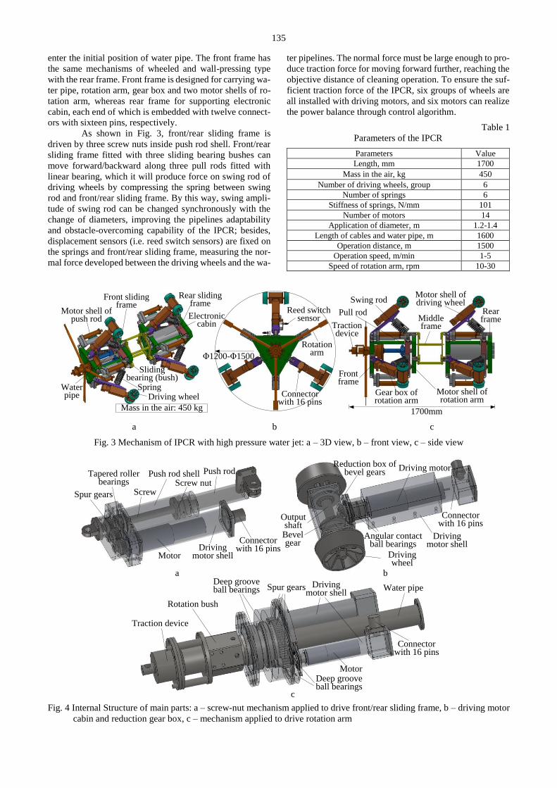
135
enter the initial position of water pipe. The front frame has
the same mechanisms of wheeled and wall-pressing type
with the rear frame. Front frame is designed for carrying wa-
ter pipe, rotation arm, gear box and two motor shells of ro-
tation arm, whereas rear frame for supporting electronic
cabin, each end of which is embedded with twelve connect-
ors with sixteen pins, respectively.
As shown in Fig. 3, front/rear sliding frame is
driven by three screw nuts inside push rod shell. Front/rear
sliding frame fitted with three sliding bearing bushes can
move forward/backward along three pull rods fitted with
linear bearing, which it will produce force on swing rod of
driving wheels by compressing the spring between swing
rod and front/rear sliding frame. By this way, swing ampli-
tude of swing rod can be changed synchronously with the
change of diameters, improving the pipelines adaptability
and obstacle-overcoming capability of the IPCR; besides,
displacement sensors (i.e. reed switch sensors) are fixed on
the springs and front/rear sliding frame, measuring the nor-
mal force developed between the driving wheels and the wa-
ter pipelines. The normal force must be large enough to pro-
duce traction force for moving forward further, reaching the
objective distance of cleaning operation. To ensure the suf-
ficient traction force of the IPCR, six groups of wheels are
all installed with driving motors, and six motors can realize
the power balance through control algorithm.
Table 1
Parameters of the IPCR
Parameters Value
Length, mm 1700
Mass in the air, kg 450
Number of driving wheels, group 6
Number of springs 6
Stiffness of springs, N/mm 101
Number of motors 14
Application of diameter, m 1.2-1.4
Length of cables and water pipe, m 1600
Operation distance, m 1500
Operation speed, m/min 1-5
Speed of rotation arm, rpm 10-30
Driving wheel
Reed switch sensor
Rear frameMiddle
frameTraction device
Rotation arm
Water pipe
Spring
Swing rod
Pull rodElectroniccabin
Front sliding frame
Rear sliding frame
Motor shell of rotation arm
Gear box of rotation arm
Motor shell of driving wheel
Motor shell of push rod
Sliding bearing (bush)
Connector with 16 pins
Mass in the air: 450 kg
Φ1200-Φ1500
1700mm
Front frame
a b c
Fig. 3 Mechanism of IPCR with high pressure water jet: a – 3D view, b – front view, c – side view
Motor
Screw nutScrewSpur gears
Push rod Push rod shell Driving motor
Driving motor shell
Driving wheel
Bevel gear
Reduction box of bevel gears
Connector with 16 pins
Connector with 16 pins
Angular contact ball bearings
Tapered roller bearings
Output shaft
Motor
Driving motor shell
Connector with 16 pins
Water pipe
Traction device
Deep groove ball bearings Spur gears
Deep groove ball bearings
Rotation bush
Driving motor shell
a b
c
Fig. 4 Internal Structure of main parts: a – screw-nut mechanism applied to drive front/rear sliding frame, b – driving motor
cabin and reduction gear box, c – mechanism applied to drive rotation arm

136
Fig. 4 is the internal structure of some main parts
of the IPCR. Fig. 4, b is the internal structure of driving mo-
tor cabin and reduction gear box, and driving torque is de-
veloped for driving wheels by reduction transmission of a
pair of bevel gears. Also, Fig. 4, c is the internal structure of
mechanism applied to drive rotation arm. Rotation bush fit-
ted with rotation arm can be rotated by reduction transmis-
sion of spur gears.
2. Traction force analysis of the IPCR
When the IPCR is running inside the water pipe-
lines, its output of traction force depends on the pressure ex-
erted on the driving wheels and friction factor between the
driving wheel and pipe wall; yet the self-weight of the IPCR
is relatively small, preload mechanism is applied to ensure
the full contact between driving wheels and pipe wall, real-
izing proper operation of the IPCR and exporting enough
traction force [16, 17].
2.1. Mechanical principle analysis of preload mechanism
Fig. 5 is the free-body diagram of preload mecha-
nism applied by the IPCR. With the symmetry of preload
mechanism, only a set of driving wheel was analyzed below.
By screw-nut mechanism driven by motor, the front/rear
sliding frame will move forward along pull rods to produce
the tension force F. The force F will compress the tension
spring, producing the spring force Fs on the hinge joint D.
Finally, three sets of driving wheels are evenly distributed
around the circumference through links BC, CD and CB and
are in full contact with the water pipe, producing the normal
pressure Fn and fraction force Ft. Supposing the IPCR
moves along the water pipelines with uniform velocity, and
preload mechanism can therefore be considered to be at rest
and be analyzed further, where the body of IPCR is fixed
[18].
As shown in Fig. 5, the coordinate Oxy is set at the
centerline of the water pipelines. The xy plane coincides
with the symmetrical cross section of the water pipelines
while y axis passes through the hinge joint C. Where T is the
driving torque exerted on the driving wheels; rd is the radius
of the driving wheels; α, β and γ are the structure angle of
preload mechanism respectively; L, L1 and L2 are the length
of links BC, CD and DB respectively; H is the distance from
hinge joint C to x axis.
The constraint equations of hinge joint A and B are
established as follows:
0 1
0 1
,
A
B
B
x L x cos L cos
x Lcos
y Lsin H
L x sin L sin
BCD
(1)
where:
2 2,
2
dd H rarcsin
L
(2)
2 2 2
1 2
1
,2
L L Larccos
LL
(3)
where: d is the inner diameter of the water pipelines; and L0, Δx are the original length and amount of compression of the
tension springs respectively.
Ft
T
v
Fs
F
αβ
Ox
yH
Pull rod
Tension spring
Screw
Screw nutPull rod
shell
Pipe wall
Driving wheel
Sliding frame
L
L2
L1
A
B
C
D
E J
Centerline of pipelines
rd
γ
Fn
Fig. 5 Free-body diagram of preload mechanism
According to the principle of virtual work, the sys-
tem of preload mechanism which is in equilibrium at this
position is given an arbitrary virtual displacement, the net
work done by the external forces (including the normal pres-
sure Fn, fraction force Ft and spring force Fs) during the dis-
placement is zero [19], i.e.:
0.iF n B s A t BW F y F x cos F x (4)
Eq. (1) can be differentiated and the following
equations are obtained:
1
.
A
B
B
x L tan cos sin
x Lsin
y Lcos
(5)
A relation exists between the fraction force Ft and
normal pressure Fn, the spring force Fs and compression of
tension spring Δx. And the relation can be expressed as:
,t nF F (6)
,sF k x (7)
where: μ is the fraction coefficient between the driving
wheels and water pipelines wall; k is the stiffness coefficient
of the tension springs.
Also, a relation exists between the spring force Fs
and the tension force F. And the relation can be expressed
as:
,sF Fcos (8)

137
Substituting Eqs. (5)–(7) into Eq. (4), the normal
pressure Fn developed by the preload mechanism can be ob-
tained:
1 .n
k tan cos sin cosLF x
L cos sin
(9)
2.2. Analysis of traction force
To realize proper operation of the IPCR and export
enough traction force, we must guarantee the adequate nor-
mal pressure Fn between driving wheels and water pipelines
wall. The normal pressure depends on the force developed
by the preload mechanism and the self-weight of the ICPR
[20]. The normal force generated by self-weight of the IPCR
under the condition of the full contact between driving
wheels and pipe wall will be analyzed below. Supposing the
axis of the IPCR is parallel to the pipelines’ axis, while the
mass of the IPCR is not uniformly distributed so that the
gravity shared by the front wheels and rear wheels is incon-
sistent. We therefore firstly studied the gravity shared by the
front wheels and rear wheels respectively.
Fig. 6 is the free-body diagram of the cross section
of the driving wheels when the attitude angle of the IPCR
inside the pipelines is φ. As shown in Fig. 6, the coordinate
Oxy is set at the intersection point of the cross section of the
driving wheels and the centerline of the water pipelines. The
xy plane coincides with the cross section of the driving
wheels while x axis is horizontal. Where FnGi (i=1, 2,...,6) is
the normal force developed by the gravity of the IPCR and
exerted on each wheel; Gf and Gr
are the gravity shared by
the front wheels and rear wheels respectively while fG and
rG are the reaction force of Gf and Gr respectively; s is the
distance between the front wheel and rear wheel; θ (
0 90 ) is the obliquity angle of the pipelines; s1 and
s2 are the distance from the front/rear wheel to the gravity
center of the IPCR respectively.
O x
y
C
ss1
s2
Pipe wall
G
Wheel 1(4)
Wheel 2(5)
Wheel 3(6)
Gf(r)
FnG3(6)
FnG1(4)
FnG2(5)
φ
Gfʹ
Grʹ
θ
Wheel 1Wheel 4
Wheel 3
Wheel 6
Wheel 2
Wheel 5
y
y
Fig. 6 Free-body diagram of the cross section of the driv-
ing wheels
According to the equilibrium condition of general
planar force system, equilibrium equations within the verti-
cal section of pipelines can be obtained:
0, 0,y f rF G G Gcos (10)
1 20, 0,C f rM G s G s (11)
where:
1 2 ,s s s (12)
, ,f f r rG G G G (13)
By solving Eqs. (11)–(13), the force Gf and Gr can
be obtained:
2
1
.f
r
sG Gcos
s
sG Gcos
s
(14)
Also, equilibrium equations within the horizontal
section of pipelines can be obtained:
1(4) 2(5)
3(6)
0, 120
120 0,
x nG nG
nG
F F sin F sin
F sin
(15)
1(4) 2(5)
3(6)
0, 120
120 0,
y nG nG
nG
F F cos F cos
F sin
(16)
where: φ is the attitude angle of the IPCR inside the pipe-
lines, and the direction of increasing φ is the
clockwise di-
rection.
Owing to the structural symmetry of the IPCR, the
normal force exerted on the driving wheels only need to be
analyzed with the attitude angle φ ranged from -30° to 90°.
The normal force generated by the gravity of the IPCR and
exerted on the top driving wheel is zero within the range of
certain attitude angle [21].
When -30° ≤ φ ≤ 60°,1(4) 0nGF . Substituting it
into Eqs. (15) and (16), and the following equations can be
obtained:
( )
2(5)
( )
3(6)
120
240.
120
240
f r
nG
f r
nG
G sinF
sin
G sinF
sin
(15)
Also, when 60° ≤ φ ≤ 90°,2(5) 0nGF . Substituting
it into Eqs. (15)–(16), and the following equations can be
obtained:
( )
1(4)
( )
3(6)
120
120.
120
f r
nG
f r
nG
G sinF
sin
G sinF
sin
(16)
When each part of the IPCR is assembled together
well and the IPCR is put to the initial position of the water
pipelines, the springs on the preload mechanism are com-
pressed in a certain extent because of the self-weight of the
IPCR. Therefore, initial preloading force of the preload
mechanism can just support the self-weight of the IPCR
when all the swing rods are fully opened and the top driving

138
wheels are just in contact with the pipelines wall. Substitut-
ing Eqs. (8) and (17)–(18) into Eq. (9), the initial preloading
force generated by the preload mechanism of each spring
can be obtained:
If -30° ≤ φ ≤ 60°,
0
1(4)
( )0
2(5)
( )0
3(6)
0
120,
240
120
240
s
f r
s
f r
s
F
G sinF k
sin
G sinF k
sin
(17)
where: 0 ( 1, 2,...,6)siF i is the initial preloading force needed
for each spring, and:
1
.cos sinL
kL tan cos sin cos
(18)
Also, if 60° ≤ φ ≤ 90°,
( )0
1(4)
0
2(5)
( )0
3(6)
120
120
0 .
120
f r
s
s
f r
s
G sinF k
sin
F
G sinF k
sin
(19)
So from the Eqs. (14) and (19)–(21), the total initial
preloading force needed for supporting the self-weight of
the IPCR can be obtained:
0
( )0
, 30 60,
30 ,60 90sf r si
k GcosF F
k Gsin
(20)
where:
2(1)
1
2,
t
s cos sin cosLk
L s an cos sin cos
(21)
In Eq. (22), Fsf(r)0 is the total initial preloading force
of the three front/rear springs and is used for supporting the
self-weight of the IPCR.
Considering the type of friction between the driv-
ing wheels and pipe wall is rolling friction, so their friction
resistance can be neglected. Therefore, from Eqs. (7)–(8),
(10) and (22)–(23), the total traction force FT of the IPCR
can be obtained:
0 0 ,T sf sf sr srF F F F Fk
(22)
where: Fsf and Fsr are the total spring preloading force of all
the front and rear springs respectively.
From Eqs. (19)–(21) can be seen, when all the
swing rods are fully opened and the top driving wheels are
just in contact with the pipelines wall, the initial preloading
force values of each spring needed for supporting the swing
rods is different. However, due to the structural symmetry
of the IPCR and the constraint between the front/rear sliding
frame and pull rods, the front/rear sliding frame driven by
screw-nut mechanism moves forward to develop three ten-
sion forces F, whose values is identical. Considering the fac-
tors above, we knew each spring force is different, which
will lead to the axis of the IPCR is not parallel to the pipe-
lines’ axis, exacerbating the self-deformation of the IPCR
and increasing the power consumption. To solve this prob-
lem and increase simultaneously the total traction force of
the IPCR, the mode of multi-motor drive was used in our
design and six motors finally realize the power balance
through control algorithm.
Besides, from Eqs. (19)–(21) we can know, if the
attitude angle 0 , the following equations can be ob-
tained:
0 0 0
1(4) 2(5) 3(6) ( )0, ,s s s f rF F F k G (23)
Also, if the attitude angle 60 , the following
equations can be obtained:
0 0 0
1(4) 2(5) 3(6) ( )0, ,s s s f rF F F k G (24)
From Eqs. (25)–(26), when the IPCR enters the in-
itial position of the pipelines, the typical attitude ( 0 or
60 ) of the IPCR can be adopted to reduce the self-de-
formation.
2.3. Necessity analysis of initial preloading force
As we can know from the results described above,
when each part of the IPCR is assembled together well and
the IPCR is put to the initial position of the water pipelines,
all the springs of the preload mechanism must be exerted
preloading force, which is used for not only supporting the
self-weight of the IPCR but also providing the normal force
for the generation of traction force. Supposing when the
IPCR just enters the initial position of the pipelines, all the
springs of the preload mechanism are not compressed and
are in the state of original length. In this extreme case, it will
lead to vibration of the IPCR caused by the misdistribution
mass and the mass center does not coincide with the geo-
metrical center.
According to the actual condition and performance
requirements, any vibration of an object can be simplified
as different vibration model [22]. Therefore, without con-
sidering the self-elastic deformation of the IPCR and un-
spring mass and taking the IPCR as a bar (rigid body), the
vibration of the IPCR in vertical plane can be simplified as
damped vibration of the system with two degrees of freedom
[22], as shown in Fig. 7. Where C is the mass center of the
bar, which does not coincide with the geometrical center; l
is the bar lengths; d is the distance between two springs; l1,
l2 (l1≠l2) is the distance between spring and mass center re-
spectively, and l3, l4 (l3≠l4) is the distance between bar end
and adjacent spring respectively; k1, k2 is the equivalent stiff-
ness coefficient of front and rear springs, and c1, c2 is the
equivalent damping coefficient of damper. Taking equilib-

139
rium position of the system as the origin, and only the dis-
placement of the vertical direction of the vibration system
and the pitch vibration around the mass center was consid-
ered. So the displacement xC of mass center and angle dis-
placement ψ around the mass center (the direction of in-
creasing ψ is the
clockwise direction) was defined respec-
tively as the generalized coordinates of the vibration system.
The restitution force F1 and F2 exerted on the system and the
displacement x1 and x2
are opposite in direction, so the force
F1 and F2 can be expressed as:
1 1 1 2 2 2, .F k x F k x (25)
k1 k2c1 c2
C
ld
l1 l2 l3l4
xC x2
x1
F1
F2
ψ
Fig. 7 Sketch of simplified vibration model
At this point, the coordinate of mass center xC can
be expressed as:
1
1 2 1 .C
lx x x x
d (26)
And the slight angle displacement ψ around the
mass center can be expressed as:
2 1 .x x
d
(27)
According to the differential equation of plane mo-
tion of a rigid body [19], the differential equation of plane
motion of the system can be obtained:
1 2 1 1 2 2
1 1 1 1 2 2 2 2
,C
C
mx F F c x c x
J F c x l F c x l
(28)
where: m is the mass of the bar; JC is the moment of inertia
of the bar around the axis which is through the mass center
and is perpendicular to the motion plane.
Considering all the springs mounted on the IPCR
are identical, so:
1 2 1 2, ,k k c c (29)
1 2 .d l l (30)
Substituting Eqs. (27)–(29) and (31)–(32) into the
Eq. (30), the vibration equations of the simplified vibration
system of the IPCR can be obtained:
1 1 1 2
1 1 1 2
2 2
1 2 1 1 1 2
2 2
1 2 1 1 1 2
2
2 0
.
0
C C
C
C C
C
mx c x c l l
k x k l l
J c l l x c l l
k l l x k l l
(31)
Eqs. (33) can be simplified to matrix form as fol-
low:
0,MU CU KU (32)
When time 0t , the initial conditions of the sim-
plified vibration system are as follow:
0 0 0 0
1
, 0; 0, ,2
C C
mgx x g
k (33)
where: g is the acceleration of gravity. And in Eq. (34),
,Cx
U
(34)
,C
mM
J
(35)
1 1 2 1
2 2
1 2 1 1 1 2
2,
c c l lC
c l l c l l
(36)
1 1 2 1
2 2
1 2 1 1 1 2
2,
k k l lK
k l l k l l
(37)
where: U is the generalized coordinate matrix of the system,
M is the mass matrix of the system, C is the damping matrix
of the system, K is the stiffness matrix of the system.
From the analysis above, we conclude the vibration
of the IPCR in vertical plane can be simplified as damped
vibration of the system with two degrees of freedom and its
vibration equations is as shown in Eq. (34). According to the
mechanical vibration theory, the vibration of the IPCR be-
longs to free vibration with viscous damping, and its initial
excitation is the self-weight of the IPCR.
As we know, the system with slight damping is
damped free vibration while the system with large damping
is not damped free vibration but exponential attenuation mo-
tion, which will attenuate to zero in a short time [23]. How-
ever, no matter what vibration form the IPCR is, the IPCR
may fail to start properly to move forward and the high pres-
sure water jet cleaning device cannot work properly in initial
position of the pipelines, which is most likely to cause the
cleaning system crash. Therefore, its initial excitation
caused the self-weight of the IPCR will be weaken by add-
ing initial preloading force of all springs, and this is the most
efficient way to ensure proper operation of the IPCR.
Also, from the analysis of traction force, when the
attitude angle of the IPCR is 0°, the deformation of all
springs is relatively small; besides, the equivalent stiffness
coefficient k1 and k2 of simplified vibration system becomes
relatively larger, which can reduce vibration of the IPCR.

140
So setting the attitude angle 0 is in initial position also
an efficient way to ensure proper operation of the IPCR.
3. Obstacle-overcoming capability analysis of the IPCR
To ensure the traveling capability of the IPCR, in
our design, the mode of multi-motor drive was used for in-
creasing the total traction force of the IPCR and six motors
can be controlled separately. And front/rear sliding frame
which can move forward/backward along three pull rods
was applied for improving the pipelines adaptability and ob-
stacle-overcoming capability of the IPCR. All possible ob-
stacles inside pipelines may stop the IPCR from proper op-
eration, so obstacle-overcoming is a necessary capability of
the IPCR.
3.1. Mechanical model of obstacle-overcoming
In this paper, only the typical obstacle inside pipe-
lines is analyzed due to length limitations, i.e. the change of
diameters. Also, supposing the IPCR moves along the water
pipelines with uniform velocity and the axis of the IPCR
keeps in the horizontal direction before meeting the obsta-
cle. Fig. 8 is the mechanical model of obstacle-overcoming.
Where Fnλi (i =1, 2, 3 or 4, 5, 6) is the normal pressure and
Ftλi (i =1, 2, 3 or 4, 5, 6) is the fraction force exerted on driv-
ing wheel at contact point; λ is the angle of obstacle-over-
coming and θ (0° ≤ θ ≤ 90°) is the obliquity angle of the
pipelines; h is the height of obstacle-overcoming; rd is the
radius of driving wheel.
T
Pipe wall
Driving wheel
B
rd
Fnλi
Ftλi
λ h
θ
Fig. 8 Mechanical model of obstacle-overcoming (diameter
becomes smaller)
The normal pressure and fraction force exerted on
three front/rear driving wheels will be changed at the mo-
ment of contacting the obstacle. From Eq. (9), the normal
pressure Fnλi of obstacle-overcoming wheel without sliding
can be obtained:
1 ,n i
k tan cos sin cosLF x
L cos sin
(38)
In Eq. (40):
1 ,d
harccos
r
(39)
If the wheels of obstacle-overcoming are the front
(rear) three driving wheels, and we know the traction force
of rear (front) three driving wheels keeps constant. Suppos-
ing the force Gf (Gr) shared by front (rear) driving wheels is
ignored at the moment of contacting the obstacle, while the
total traction force of rear (front) driving wheels is still cal-
culated according to Eq. (24). So when the IPCR can suc-
ceed in overcoming obstacle, the mechanical equation must
be met:
0,t i n i T LF cos F sin F F (40)
where:TF can be obtained according to Eq. (24); FL is the
total load on the IPCR.
0
0
, 1, 2,3
,
, 4,5,6
sr sr
T
sf sf
F F ik
F
F F ik
(41)
1 .L W IF uL gcos F Gsin (42)
In Eq. (44), μ1 ( 1 0.06 ) is the resistance coeffi-
cient between rolling bracket and pipe wall; u 3 kg mu
is the total mass per unit length of cables and water pipe; LW
( 0 1600mWL ) is the length of cables and water pipe
pulled by the IPCR; g is the gravity acceleration; FI is the
rolling friction resistance of the IPCR.
After the IPCR succeeds in overcoming obstacle,
the total traction force of front (rear) driving wheels can be
obtained by replacing d with ( 2d h ) in Eq. (24). Obvi-
ously the total traction force becomes large, so front (rear)
sliding frame should move backward properly to reduce the
deformation of front (rear) springs. Also, after the IPCR suc-
ceeds in overcoming obstacle (diameter becomes larger),
front (rear) sliding frame should move forward properly to
increase the deformation of front (rear) spring, providing
enough traction force for the IPCR.
3.2. Improvement of obstacle-overcoming
In Eq. (34), it was established based on the two
generalized coordinates xC and ψ, and they are principal co-
ordinates of the vibration system. Also, the displacement x1
and x2 can be defined as the generalized coordinates of the
vibration system [23]. Substituting Eqs. (27)–(29) and (31)–
(32) into the Eqs. (30), and Eqs. (33) can also be expressed
as:
2 1
1 2 1 1 1 2 1 1 1 2
1 2 1 1 1 1 2 2 1 1 1 1 2 2
0
,
0C C
ml mlx x c x c x k x k x
d d
J Jx x c l x c l x k l x k l x
d d
(43)
when time 0t , the initial conditions of the vibration sys-
tem are as follow:
10 20 10 20
1
, 0.2
mgx x x x
k (44)
In Eqs. (45), x1 and x2 can be eliminated after
proper transformation, and the following equations can be
obtained:
141
2 2 2
2 1 2
1 2 1 1 1 12 2
2 2 2
1 1 2
2 1 1 2 1 22 2
0
,
0
C C
C C
l l lm x m x c x k x
d d
l l lm x m x c x k x
d d
(45)
where: ρC is the gyration radius of the bar around the axis of
mass center.
.C
C
J
m (46)
Next, we will analyze the vibration transmission
between front and rear springs. For the convenience of
study, the damping of the vibration system is ignored, so
Eqs. (47) can be simplified as follow:
2
1 1 2 1 1
2
2 2 1 2 2
0,
0
x x x
x x x
(47)
where: η1, η2 is the coefficient of association which indicates
the relationship of x1 and x2; ω1, ω2 is the offset frequency
which indicates the vibration frequency of independent vi-
bration of front/rear springs. And if 1 0x , the vibration
frequency of the system is ω2, while if 2 0x , the vibration
frequency of the system is ω1.
2 2
1 2 1 21 22 2 2 2
2 1
, ,C C
C C
l l l l
l l
(48)
2 2
1 11 22 2 2 2
2 1
, ,C C
k d k d
m l m l
(49)
when the IPCR working inside the pipelines, we hope the
vibration of front (rear) springs of the IPCR cannot reach to
rear (front) springs. So the following relation between the
mass distribution of the IPCR and the position of front/rear
swing rods must be met:
2
1 2
1.C
l l
(50)
In Eq. (52), ε is the coefficient of mass distribution.
When ε = 1, the coefficient of association is zero,
i.e. 1 2 0 . And Eqs. (49) can be simplified as follow:
2
1 1 1
2
2 2 2
0.
0
x x
x x
(51)
Eqs. (53) shows that when 1 , the natural fre-
quency of two principal vibrations is equal to the offset fre-
quency of front and rear springs of the IPCR, i.e.:
1 11 2
2 1
, ,k k
l lm m
d d
(52)
k1 k2=k1 k1 k2=k1
ω1(x2=0) ω2(x1=0)
Fig. 9 The two principal vibrations (the natural frequency
is equal to the offset frequency ω1 and ω2)
Fig. 9 is two the principal vibrations with the fre-
quency ω1 and ω2, i.e. when rear springs vibrate up and
down at the frequency ω1, front springs keep still; when
front springs vibrate up and down at the frequency ω2, rear
springs keep still.
From Eqs. (46) and (53)–(54), the solution of Eqs.
(53) can be obtained:
1 1
1
2 2
1
2 2.
2 2
mgx sin t
k
mgx sin t
k
(53)
In the process of obstacle-overcoming, front/rear
springs of the IPCR will vibrate arising from the excitation
caused by obstacles. The stable output of traction force will
be affected. And from Eq. (55) we know, when 1 , there
is no relation between the vibration of front springs and rear
springs of the IPCR without one impacting the other. There-
fore, the reasonable arrangement of load and parts on the
IPCR should be carried out to make the coefficient of mass
distribution as equal to 1 as possible. In this way, the vibra-
tion transmission between front and rear springs can be ef-
fectively avoided, which is beneficial to the improvement of
traveling capability of the IPCR and the achievement of
power balance control for multi-motor.
4. Simulation
To testify the traveling capability of the proposed
IPCR, some basic simulations have been conducted.
4.1. Simulation environment
A virtual simulation platform including the simpli-
fied physical prototype of the IPCR and the water pipelines
is established. On the platform, the water pipelines is fixed
on the ground and the simplified physical prototype of the
IPCR complies with the actual assembly relationship shown
in Fig. 3 by the joint constraints; besides, contact constraints
are used between the driving wheels of the IPCR and the
pipe wall.
In the simulations, to fully verify the validity of the
proposed IPCR, two groups of tests including traction force
and traveling capability are implemented inside the pipe-
lines with different parameters.
4.2. Simulation of traction force
In the simulation of traction force, the typical pipe-
line in application of engineering construction is chosen and
its diameter is 1400 mm. The pipeline is placed horizontally
and is fixed on the ground. To test the maximum traction

142
force of the IPCR, a virtual spring is fixed on the back end
of the IPCR and the other end of the spring is fixed on the
ground; besides, the maximum torque exerted on the driving
wheels is the single input, and the maximum pull force is
exerted on the front/rear sliding frame to generate the max-
imum normal force between the IPCR and the pipe wall.
Fig. 10 is the obtained curves of traction force and velocity
of the IPCR, where D is the diameter of the pipelines.
As shown in Fig. 10, with the IPCR moving for-
ward, the spring fixed on the back end of the IPCR is grad-
ually stretched. As the deformation of the spring becomes
larger, the velocity of the IPCR becomes faster firstly and
then smaller. When the velocity direction of the IPCR
changes, the maximum traction force is obtained and its
value is 6865.19 N.
Setting the rolling friction resistance FI of the
IPCR is 1000 N (the coefficient of rolling friction is about
0.02), and From Eq. (44) we know, if the IPCR climbs the
sloping pipelines all the time, the maximum obliquity angle
θmax of pipelines the IPCR can conquer can be obtained:
43.8 .max (56)
Considering the water pipelines in application of
engineering construction is almost placed horizontally and
from Eq. (56) we know, the proposed IPCR is powerful with
traction force to guarantee its operation distance reach
1500 m.
1.75
-5.75
-4.5
-3.25
-2
0.5
-0.75
-70 0.5 1 1.5 2 2.5 3
1.75
-5.75
-4.5
-3.25
-2
00.5
-0.75
-7
Traction force of the IPCRVelocity of the IPCR
Time (s)
Tra
ctio
n f
orc
e (k
N)
Vel
oci
ty (
m/s
)
Fig. 10 Curves of traction force and velocity of the IPCR
(φ = 60°, θ = 0°, D = 1400 mm)
4.3. Simulation of traveling capability
4.3.1. Vibration of the IPCR in initial position
From the necessity analysis of the initial preload-
ing load, the IPCR without exerted initial preloading load
will vibrate in initial position of the water pipelines. The
way to avoid the vibration in initial position is to add initial
preloading force of all springs or set the attitude angle. In
the simulations, the pipeline is still placed horizontally and
is fixed on the ground; besides, the IPCR is not given the
torque input. Fig. 11 is the obtained curves of vibration in
initial position at the typical attitude angle.
Time (s)0 1 2 3
Dis
pla
cem
ent
(mm
)
An
gle
dis
pla
cem
ent
(°) Angle displacement of the IPCR
Displacement of mass center
0.5 1.52.
5
-50
0
50
-1.5-1
-2
-0.50
0.51
-3.5-3
-2.5
100
Time (s)0 1 2 3 4 5 6 7 8
-200
-150
-100
-50
0
50
-1.5-0.50.51.52.53.54.55.56.57.58.5
Dis
pla
cem
ent
(mm
)
An
gle
dis
pla
cem
ent
(°) Angle displacement of the IPCR
Displacement of mass center
0 1 2 3
Dis
pla
cem
ent
(mm
)
An
gle
dis
pla
cem
ent
(°) Angle displacement of the IPCR
Displacement of mass center
0.5 1.5 2.5
-0.5
0
0.5
05
-5
10152025
-20-15-10
1
-1
Time (s) Time (s)0 2 4
Dis
pla
cem
ent
(mm
)
An
gle
dis
pla
cem
ent
(°) Angle displacement of the IPCR
Displacement of mass center
1 3 5-150
-100
50
22.5
1.5
33.5
44.5
00.5
1
0a b
c d
Fig. 11 Vibration of the IPCR in initial position: a – no added initial preloading force (φ = 0°, θ = 0°); b – no added initial
preloading force (φ = 60°, θ = 0°); c – added initial preloading force (φ = 0°, θ = 0°); d – added initial preloading
force (φ = 60°, θ = 0°)
The results show there is almost no vibration after
adding the preloading force or setting the attitude angle and
the IPCR can stand still in a very short time. As shown in
Fig. 11, a–b, under the condition of no added preloading
force, the vibration with is more sharply and the amplitude
of displacement and angle displacement is much larger than
that with φ = 60°. This is because the equivalent stiffness
coefficient of simplified vibration system is relatively small
at φ = 60°. The reduction percentage of dis-placement and
angle displacement of the IPCR is shown in Table 2.
As shown in Fig. 11, c–d, after adding initial pre-
loading force, the vibration is not damped free vibration but
exponential attenuation motion, which attenuates to zero in
a short time. As the initial excitation is very small, the dis-
placement and angle displacement of the IPCR, to a great
extent, are much smaller than before (with no added initial
preloading force), as shown in Table 3. In conclusion, the
above obtained results show that setting the attitude angle in

143
initial position or adding initial preloading force of all
springs can obviously weaken vibration of the proposed
IPCR.
Table 2
Reduction percentage at two different attitude angle
(no added preloading force)
Maximum
displace-
ment
Maximum
angle dis-
placement
Final
dis-
place-
ment
Final an-
gle dis-
placement
φ=0°
vs.
φ=60°
60.5% 62.7% 0.64% 12.8%
Table 3
Reduction percentage after adding preloading force
Maximum
displace-
ment
Maximum
angle dis-
placement
Final
dis-
place-
ment
Final an-
gle dis-
placement
φ=0° 69.5% 69.7% 72.2% 73.4%
φ=60° 47.5% 48.5% 33.5% 40.4%
4.3.2. Obstacle-overcoming capability to suit multi-radius
pipeline of the IPCR
In the application of engineering construction, the
pipelines are often positioned in different posture to meet
different connection demands. So the IPCR may encounter
obstacles at the pipelines connections [2]. In the simulation,
we choose the straight pipeline with multi-radius. The diam-
eter of initial part of the pipeline is not variable and is long
enough to allow the IPCR to reach maximum velocity be-
fore meeting obstacles, as shown in Fig. 12. The torque ex-
erted on the driving wheels is the single input, and the proper
pull force is exerted on the front/rear sliding frame to gen-
erate the preloading force.
Pipe wall
v
IPCRh
Fig. 12 Straight pipeline with multi-radius (h = 30 mm,
φ = 0°, θ = 0°)
Fig. 13 shows the velocity of the driving wheels,
and the results indicate that the proposed IPCR can succeed
in passing through the pipeline with multi-radius. As shown
in Fig. 13, a–b, the velocity of all front driving wheels in-
stantly reduces and only the velocity vibration of the bot-
tom driving wheels occurs at the moment of contacting the
obstacle; the velocity instantly reduces again at the moment
of completely overcoming the obstacle. The vibration is not
transferred to the rear driving wheels. Also, when the pro-
posed IPCR jumps down the obstacle, only the velocity of
the top front driving wheel vibrates and the transition of ve-
locity is smooth. The velocity of all rear driving wheels vi-
brates with larger amplitude. This is because the mass center
of the IPCR is forward so that the front driving wheels sup-
port the majority of the IPCR’s weight; besides, the pull
force exerted on the front and rear sliding frame is identical.
So the normal pressure of rear driving wheels is relatively
small, leading to the vibration with larger amplitude.
Fig. 14 is the force on the springs at the process of
operation of the IPCR. Regardless of the front or rear
springs, the beats of force on the top spring is relatively large
and only the shock on the top spring is very large the mo-
ment the IPCR contacts the obstacle.
Driving wheel 1Driving wheel 2Driving wheel 3
Time (s)
Vel
oci
ty (
m/s
)
0
2
1
3
4
5
6
5 10 15 20 25 300
Driving wheel 4Driving wheel 5Driving wheel 6
Time (s)
Vel
oci
ty (
m/s
)
0
2
1
3
4
5
6
5 10 15 20 25 300
a b
Fig. 13 Velocity of the driving wheels: a – velocity of the front driving wheels; b – velocity of the rear driving wheels
Time (s)
Fo
rce
(kN
)
0
5
2.5
7.5
10
12.5
5 10 15 20 25 300
The bottom spring 1The top spring
The bottom spring 2
The bottom spring 1The top springThe bottom spring 2
Time (s)
Fo
rce
(kN
)
0
5
2.5
7.5
10
12.5
5 10 15 20 25 300
a b
Fig. 14 Force on the driving wheels: a – force on the front springs; b – force on the rear springs

144
To sum up, the proposed IPCR has a certain capa-
bility to overcome obstacles. Vibration between the front
and rear driving wheels in not transferred, because the ve-
locity of the IPCR is small. Considering the operation speed
of the IPCR is relatively slow or the obliquity angle of the
pipeline is not equal to zero in real application, the IPCR
needs more out-put torque to successfully overcome obsta-
cles inside pipe-lines; and the shock on the top spring can
also be decreased the moment the IPCR contacts the obsta-
cle.
5. Conclusions
This paper proposed a novel in-pipe cleaning robot
equipped with high pressure water jet and cleaning system
of water pipelines. The whole mechanism of the IPCR was
designed and the mechanisms principle of the IPCR was an-
alyzed. The total traction force of the IPCR was given out
after analyzing the mechanical principle of the preload
mechanism. The capability of obstacle-overcoming was an-
alyzed. The vibration equations of the simplified vibration
system of the IPCR were obtained. On this basis, the neces-
sity of adding initial preloading force on all springs was ver-
ified and the methods to improve the capability of obstacle-
overcoming were proposed. Simulations have been imple-
mented to verify the traveling capability of the pro-posed
IPCR. The results show that the IPCR is powerful with trac-
tion force and has a certain capability to overcome obsta-
cles. The results can give a reference to the achievement of
power balance control for multi-motor and real engineering
application in the future.
References
1. Zhu, X.; Wang, W.; Zhang, S.; Liu, S. 2017. Experi-
mental research on the frictional resistance of fluid-
driven pipeline robot with small size in gas pipeline, Tri-
bology Letters 65(2): 1-10.
https://doi.org/10.1007/s11249-017-0830-z.
2. Li, T.; Ma, S.; Li, B.; Wang, M.; Wang, Y. 2016. Ax-
iomatic design method to design a screw drive in-pipe
robot passing through varied curved pipes, Science
China Technological Sciences 59(2): 191-202.
https://doi.org/10.1007/s11431-015-5840-1.
3. Kakogawa, A.; Nishimura, T.; Ma, S. 2014. Designing
arm length of a screw drive in-pipe robot for climbing
vertically positioned bent pipes, Robotica 34(2): 306-
327.
https://doi.org/10.1017/S026357471400143X.
4. Zhang, Y.S.; Jiang, S.Y.; Zhang, X.W.; Yu, H.H.;
Wang, D.L.; Guo, D.M. 2010. Dynamic characteristics
of an intestine capsule robot with variable diameter, Chi-
nese Science Bulletin 55(17): 1813-1821.
https://doi.org/10.1007/s11434-009-3370-6.
5. Wang, Z.W.; Cao, Q.X.; Luan, N.; Zhang, L. 2010.
Development of an autonomous in-pipe robot for off-
shore pipeline maintenance, Industrial Robot: An Inter-
national Journal 37(2): 177-184.
https://doi.org/10.1108/01439911011018957.
6. Kim, H. M., Choi, Y. S., Lee, Y. G., & Choi, H. R. 2017. Novel mechanism for in-pipe robot based on a
multiaxial differential gear mechanism, IEEE/ASME
Transactions on Mechatronics 22(1), 227-235.
https://doi.org/10.1109/TMECH.2016.2621978.
7. Tătar, O.; Mandru, D.; Ardelean, I. 2007. Develop-
ment of mobile minirobots for in pipe inspection tasks,
Mechanika 68(6):60-64.
8. Jeon, W. S.; Kim, I.; Park, J.W.; Yang, H. 2013. De-
sign and control method for a high-mobility in-pipe ro-
bot with flexible links, Industrial Robot: An Interna-
tional Journal 40(3): 261-274.
https://doi.org/10.1108/01439911311309960.
9. Adria, O.; Streich, H.; Hertzberg, J. 2004. Dynamic
replanning in uncertain environments for a sewer inspec-
tion robot, International Journal of Advanced Robotic
Systems 1(1): 33-38.
https://doi.org/10.5772/5617.
10. Ma, Z.; Hu, Y.; Huang, J.; Zhang, X.; Wang, Y.;
Chen, M.; Zhu, Q.M. 2007. A novel design of in pipe
robot for inner surface inspection of large size pipes,
Mechanics Based Design of Structures and Machines
35(4): 447-465.
https://doi.org/10.1080/15397730701673296.
11. Li, P.; Ma, S.G.; Li, B.; Wang, Y. 2008. Multifunc-
tional mobile units with a same platform for in-pipe in-
spection robots, IEEE/RSJ International Conference on
Intelligent Robots and Systems, Nice, p. 22-26.
https://doi.org/10.1109/IROS.2008.4650583.
12. Liu,Q.; Chen,Y.; Ren,T.; Wei, Y. 2014. Opti-
mized inchworm motion planning for a novel in-pipe ro-
bot, Proceedings of the Institution of Mechanical Engi-
neers Part C: Journal of Mechanical Engineering Sci-
ence 228 (7):1248-1258.
https://doi.org/10.1177/0954406213502409.
13. Ratansawanya, C.; Binsirawanich, P.; Yazdanjo, M.;
Mehrandezh, M.; Poozesh, S.; Paranjape, R.; Naj-
jaran, H. 2006. Design and development of a hardware-
in-the loop simulation system for a submersible pipe in-
specting robot, IEEE Canadian Conference on Electrical
and Computer Engineering (CCECE), Ottawa, 1526-
1529.
https://doi.org/10.1109/CCECE.2006.277638.
14. Xu, F.P.; Geng, C.; Xia, Y.S. 2012. Key techniques of
robot for work of drainpipe deposit cleaning, Journal of
Harbin Institute of Technology (New Series) 19(3): 95-
99 (in Chinese).
15. Kakogawa, A.; Ma, S.G. 2010. Mobility of an in-pipe
robot with screw drive mechanism inside curved pipes,
IEEE International Conference on Robotics and Biomi-
metics (ROBIO), Tianjin p. 1530-1535.
https://doi.org/10.1109/ROBIO.2010.5723557.
16. Tang, D.W.; Li, Q.K.; Jiang, S.Y.; Deng, Z.Q.; Liu,
H. 2011. Design and analysis of a pipeline robot with the
function of differential movement, Journal of Mechani-
cal Engineering 47(13): 1-8 (in Chinese).
https://doi.org/10.3901/JME.2011.13.001.
17. Tatar, M.O.; Cirebea, C.; Mandru, D. 2012. The de-
velopment of an in-pipe minirobot for various pipe sizes,
IEEE International Conference on Automation Quality
and Testing Robotics (AQTR), Cluj-Napoca, p. 443-
448.
https://doi.org/10.1109/AQTR.2012.6237751.
18. Cai, Z.Q.; Lin, C.; Huo, D.H.; Zhu C.C. 2017. Design
and analysis of cleaning mechanism for an intermittent
screw-driven pipeline robot, Journal of Mechanical Sci-
ence and Technology, 31(2): 911–921.
https://doi.org/10.1007/s12206-017-0144-y.

145
19. Hong, J.Z.; Liu, Z.Y.; Yang, C.J. 2015. Theoretical
Mechanics, Higher Education Press, Beijing.
20. Li, Q.K.; Tang, D.W.; Jiang, S.Y.; Deng, Z.Q. 2012.
Research and simulation on the driving property of a tri-
axial differential pipeline robot, Journal of Harbin Engi-
neering University 33(6): 753–758 (in Chinese).
21. Tang, D.W.; Li, Q.K.; Jiang, S.Y.; Deng, Z.Q. 2010.
Differential property and traction force of tri-axial dif-
ferential pipeline robot in elbow, Robot, 32(1): 91-96 (in
Chinese).
https://doi.org/10.3724/SP.J.1218.2010.00091.
22. Zhang C. 2008. Machinery Dynamics. Higher Educa-
tion Press, Beijing.
G. Feng, W. Li, Z. Li, Z. He
DEVELOPMENT OF A WHEELED AND WALL-
PRESSING TYPE IN-PIPE ROBOT FOR WATER
PIPELINES CLEANING AND ITS TRAVELING
CAPABILITY
S u m m a r y
Most of existing in-pipe robots are applied to de-
fect inspection and regular maintenance, etc. There is almost
no in-pipe robot for big-diameter pipelines cleaning and are
still problems of traction force and obstacle-overcoming. To
deal with the problems, a novel wheeled and wall-pressing
type in-pipe cleaning robot (IPCR) with high pressure water
jet is proposed. Then the preload mechanism, traction force,
and obstacle-overcoming capability of the IPCR are ana-
lyzed. The vibration equations of the simplified vibration
system of the IPCR are established. Also, the necessity of
preloading force is verified and methods to improve obsta-
cle-overcoming capability are proposed. Finally, the travel-
ing capability is verified in a dynamics simulation system.
The simulation results show that the proposed IPCR is pow-
erful with traction force and has a certain capability of ob-
stacle-overcoming. Setting the attitude angle is zero and
adding preloading force to all springs can obviously weaken
vibration of the IPCR.
Keywords: wheeled and wall-pressing type in-pipe clean-
ing robot (IPCR), preload mechanism, traction force, obsta-
cle-overcoming capability, simplified vibration system.
Received August 08, 2017
Accepted April 15, 2020