Embed Size (px)
Citation preview

DEVELOPMENT OF A TOOL CHANGING ROBOT FOR A COMPUTER NUMERICALLY CONTROLLED MILLING MACHINE
Craig David Read
A research report submitted to the Faculty o f Engineering, University of the Witwatcrsrand, in partial fulfillment of the degree o f Master o f Science in Engineering
Johannesburg, .1999

D E C L A R A T IO N
I declare that this report is my own, unaided work. It is being submitted for the degree o f Master o f Science at the University o f the Witwatcrsrand, Johannesburg. It has not been submitted before for any degree or examination at any other University.
(Signature o f Candidate)
t '2 ' " day o f (S '- (year) / V / 9
ii

A B ST R A C T
The Industrial Engineering department at the University o f the Witwatcrsrand is
currently developing a Flexible Manufacturing Cell (FMC) for local application.
One o f the components o f this FMC is a Computer Numerically Controlled (CNC)
Milling Machine, for which a tool change robot was designed and built in 1991.
The project was never completed and over the years the condition o f the robot
deteriorated and parts o f the control system were damaged or lost.
This report documents the redevelopment o f the tool change robot. The control
system has been modified and suitable replacement components incorporated into
the design. An external interface with the CNC Milling Machine has been
developed, and the software has been completely rewritten in a modular manner
for increased functionality. In its current state, the Robot is capable performing an
automated tool change.

CONTENTS
Page
TITLE PAGE IDECLARATION IIABSTRACT III
LIST OF FIGURES VIL IST O F T A B LES VIIN o m e n c l a t u r e v iii
1 INTRODUCTION_____________________________________________________ 1
1.1 in t r o d u c t io n t o R o b o t ic s i
1.2 T h e M e c h a n i c a l S t r u c t u r e o k r o b o t s 21.3 R o b o t ic C o n t r o l S y s t e m s 21.3.1 Choice of Controller_____________________________________________ &1.4 S e n s o r s a n d A c t u a t o r s 51.4.1 Stepping Motors_________________________________________________6
2 HISTORY OF THE TOOL CHANGE ROBOT____________________________ §
3 _ STATEMENT OF THE PROBLEM_____________________________________IQ
3.1 S t a t e m e n t o f t h e S u b - p r o b l e m s 10M J _____Mechanical Design___________ IQ
3.1.2 Control System________________________________________ IQ
2 iU ____ Interlace to The Milling Machine_________________________________ U
3.2 D e l im it a t io n ’s 11
_4_EXISTING EQUIPMENT_____________________________________________ U
4.1 P C C o n t r o l l e r 124.2 S t e p p e r M o t o r a n d C o n t r o l l e r 124.3 r e l a y C o n t r o l C a r d 124.4 M e c h a n ic a l St r u c t u r e 134.5 INSTRUMENTATION 13
5 THE ROBOT CONTROL SYSTEM______________________ ... .14
5.1 T h e O r ig in a l C o n t r o l s y s t e m 145.2 C h o ic e o f C o n t r o l l e r i s5.3 O v e r v ie w o f C o n t r o l S y s t e m 16
iv

5.4 IN T E R F A C E W IT H T H E CNC M ILL5.5 R e p l a c e m e n t o f S e n s o r s
5.6 W ir in g o f t h e M a in C o n t r o l U n it
232425
6 THE SOFTWARE 30
6.1 O v e r v ie w o f t h e S o f t w a r e
6.2 O p e r a t in g t h e S o f t w a r e
6.3 D e t a il e d D e s c r ip t io n o f S o f t w a r e P r o c e d u r e s
303232
7 MECHANICAL MODIFICATIONS 39
8 CONCLUSION 43
9 FURTHER WORK REQUIRED 46
10 REFERENCES 47
APPENDIX A 49
APPENDIX B 83
APPENDIX C .................. 92
V

3
3
6
7
14
17
IS20
21
22
26
27
28
29
29
29
38
40
41
42
45
45
L IST OF FIG U R E S
Open Loop Control
Closed Loop Control
Rotor o f a Stepping Motor
Energi .ing Sequence o f a Four-Pole Stepping Motor
Overview o f the Original Control System
Overview o f the Implemented Control System
PCL-838 37 Pin Assignment
Pin Assignment for Main Controller 37-Pin Connector
Top View o f the Main Control Unit
Main Control Unit
Wiring o f the Stepping Motor Driver
PC-38 Computer Relay Adapter Card
Wiring Diagram for 24V Relay Card
Wiring Diagram for (9-Pin) Mill Interface
Wiring Diagram for Solenoid Actuators
Wiring Diagram for Sensor Connector
Flow Diagram for Main Software Sequence
Overview o f Robot showing new Support Frame
New Tool Holder Support Frame
New Robot Support Stand
Overview o f Robot (photograph)
Robot Ann Extended to Retrieve Tool from Mill

FUGURE PAGE
B1 Overview o f Robotic Arm with Original Frame 84
B2 Robotic Arm Gripper Assembly 85
B3 Protractor & Indicator Details 86
B4 Tool Holder 87
35 Tool Locator Details 88
B6 Main Support Frame 89
B7 Vertical & Horizontal Guides 90
B8 Vertical Guide Arm 91
L IS T O F T A B L E S
TABLE PAGE
5.1 Pin Assignments for PCL-838 Card 19
6.1 Robot Positions Corresponding to Binary Outputs 37
vii

N O M E N C L A T U R E
AC Alternating Current
CIS Computer Numerical Control
DC Direct Current
DCS Distributed Control System
FMC Flexible Manufacturing Cell
I / O Input / Output
OOP Object Orientated Programming
PC Personal Computer
PLC Programmable Logic Controller
TSR Terminate and Stay Resident software
viii

DEVELOPMENT OF A TOOL CHANGING ROBOT
1 INT RODUCTION
1.1 Introduction to Robotics
From the moment people started doing work, they began to find methods of
automating the work. However, the term robot and robotics are o f recent
origin, and were first used by a Czechoslovakian dramatist, Karel Capek in
his 1921 play (Fuller 1991). These robots were designed to perform perfect
and tireless manual labour.
The industrial robot has been developed to assist people with manual work.
Yet the term robot is commonly misunderstood, and often confused with
terms such as automation. Even within the industrial world, there is no
single definition for a robot. The Japanese have defined a robot as an all
purpose device equipped with a memory device and a terminal, and capable
o f rotation and o f replacing human labour by automatic performance o f
movement (Fuller 1991). However, this definition could include numerous
automated devices such as bottling machines, or even a modem washing
machine.
The Robotic Association o f America defines a robot as 'a reprogrammable,
multifunctional manipulator designed to move material, parts, tools, or
specialised devices, through variable programmable motions, fo r the
purpose o f a variety o f tasks'. ' r 4om industrial robots are commonly used
for repetitive, unskilled or semiskilleu, monotonous and burdensome tasks,
as well as jobs that would be hazardous for a person to perform. They are
distinguished from hard automation due to them not performing a single
specific task.
While industrial robots and automated machines are usually treated as
separate topics, most industrial robots work in co-operation with other
1

DEVELOPMENT OF A TOOL CHANGING ROBOT
automated machines. Therefore any robot must interface with the
environment in order to obtain information regarding the task to be
performed.
The study o f robotics covers many disciplines: mechanical, electrical
electronic, computing and control engineering. There are severe constraints
on any robot design, most notably that the robot must be capable of
performing useful tasks in real time, at an affordable cost.
1.2 The Mechanical Structure of Robots
A robot must have a mechanical structure to move an object around, and
also an end effector to hold a tool or grip a part. Typically the mechanical
structure is constructed from a series o f rigid links, connected by joints. The
particular type o f joint defines how one link can move relative to the other.
The two most common type o f joints are prismatic and revolute. A
prismatic joint, also known as a sliding joint, allows one link to move in a
straight line relative to another. A revolute joint takes the form o f a hinge
between one joint and another, In pranice there are a vast number of
configurations used.
A major consideration in the design o f a robot is to keep the links as light as
possible to reduce the response time and the force required to move them,
while keeping them as rigid as possible.
1.3 Robotic Control Systems
For any specific mechanical robotic structure, it will be necessary to control
the movements o f each part o f the mechanism in order that the end effector
can be moved to a required position and orientation in space. Broadly
2

DEVELOPMENT OF A TOOL CHANGING ROBOT
speaking, two types o f control can be used, namely Open Loop control and
Closed loop control.
r«)actuato r
u(t)load
Pit)
inputsignal
ou tpu t
F IG U R E t . l O PE N LO O P C O N T R O L
Oh )p control is shown schematically in Figure 1,1, No feedback or
measure o f the output position is taken, so this control relies wholly on good
calibration and the reliable behaviour of the actuator system.
loadinputsignal
ell) = r(t) - Mil Is, in this case, the e rror signal
u ( t )
outpu t
F IG U R E 1,2 C LO SE D L O O P C O N T R O L
Closed Loop control is depicted in Figure 1.2. As shown, there is a
feedback signal indicating the current position, which is used as a
dill error to continuously correct the driving signal to achieve
accuuuu control.
3

DEVELOPMENT OF A TOOL CHANGING ROBOT
1.3.1 Choice o f Controller
The choice o f the correct controller for ontomation applications has long
been the subject o f debate. Traditionally, a PLC was considered the only
option for plant automation due to their rugged construction, dedicated
control functionality and lower cost. A PC was only considered suitable for
office applications. However in more recent years, the PC has gained much
ground in this field. This is largely the result o f high power PC’s becoming
extremely economical in the highly competitive environment, and the
relative simplicity and power o f modem programming interfaces dedicated
to control software.
“Why PC’s won’t kill PLC’s” (Hohmann, 1987) reviews the situation, and
concludes that for the majority o f traditional industrial applications, the
PLC is still better suited and more economical for automation and control.
This is largely due to the dedicated architecture o f a PLC which is
specifically designed for both analogue and digital I/O, w lr 'e PC’s require
special control interfaces.
However, provided that the environment is not particularly harsh, the PC
still has the advantage o f greater flexibility and programmability, and
therefore functionality. These devices can be programmed in a number o f
standard commercial programming languages such as C, C++, Pascal or
Forth. Furthermore, ‘Soft’ PLC software allows a PC to be programmed
and function like a PLC, giving the benefit o f both systems.
“Take advantage o f control options” (Banvise, Moodley 1998) also reviews
various control options, including PLC’s, P C s and DCS’. The choice of
controller is ultimately dependent on the particular application, and the
specific requirements such as level o f desired discrete or process function,
operational speed, electrical power requirements, the environment,
flexibility for future changes, and the budget. One important consideration
4

DEVELOPMENT OF A TOOL CHANGING ROBOT
raised is the rapid technological advancement in the PC industry, which
renders a PC redundant within a few years o f purchase. This problem does
not exist in the relatively stable PLC industry.
As already discussed, there have been tremendous advances in application
software for industrial automation. The current trend in software
development is Object Orientated Programming (OOP). The goal o f this
type o f programming is to save time through developing objects that are re
usable, thus allowing software developers to create libraries f functions and
procedures. These objects differ from traditional functions and procedures
in one fundamental manner, they contain data in addition to functions that
operate on that data. Most common modem programming languages such
as Turbo Pascal 5.5 or higher, and C++ support object orientated
programming.
1.4 Sensors and Actuators
In order to move the mechanical structure o f a robot, actuators are required.
There are a number o f alternate ways o f actuating a mechanical link, which
broadly speaking can be divided into pneumatic, hydraulic and electric. All
o f these can give either rotary or linear motion.
Typically pneumatic actuators comprise a cylinder and valves which control
the flow o f fluid to it from a high pressure supply. There is an extensive
range o f standard actuators available to select from, depending on the nature
o f the movement, the distance to be moved, and the force required, which is
a function o f the pressure and diameter o f the cylinder.
Electric actuators are typically electric motors, operating using either AC
and DC supplies. Numerous specialised types are available including servo
drives and stepper motors,5

DEVELOPMENT OF A TOOL CHANGING ROBOT
1.4.1 Stepping Motors
The main feature, o f a stepping motor is that for a given sequences o f
pulses or steps, the output shaft o f the motor will rotate an angle directly
proportional to the number o f pulses. The rotor comprises a permanent
magnet with its axis lying along the axis o f rotation o f the rotor. Each end
o f the magnet is shaped like a toothed wheel, with the North-pole teeth
radially displaced one-half tooth pitch from the South-pole teeth, as is
shown in Figure 1.3 (a).
d e t a i l
e n d v ie w s i d e v ie w
FIG U R E 1.3(a) R O T O R O F A S T E PP IN G M O T O R
Multiple stator windings are distributed around the periphery. There are
energised electrically. An energising sequence for a four-phase stepping
motor is shown in Figure 1.3 (b - e),
6

DEVELOPMENT OF A TOOL CHANGING ROBOT
s ta to rw in d in g s ro to r o tf
o iloff
J 2 H
off
FIG U R E 1.3(b-c) E N E R G ISIN G SE Q U E N C E O F FO U R -PO L E S T E PP IN G M O T O R
As the windings are sequentially energised, the rotor will be displaced a
half-tooth radially in order to reach a stable state. For each successive
positive or negative step the motor will rotate a half-tooth radially,
A useful feature is the static holding torque in each stable state, which will
tend to hold the rotor in the correct position even when an external torque
is applied, The number o f teeth and stator windings determines the
resolution o f the motor, or step size.
I f an accurate pulse count is kept, then the angular position o f the rotor is
known with respect to it’s position at the start o f the count, and the
stepping motor can be operated open loop, so positional feedback sensors
(such as roraty encoders) are not required. For this reason stepping motors
are popular in applications where cost is an important constraint.
7

DEVELOPMENT OF A TOOL CHANGING ROBOT
2 HISTO RY OF THE TOOL C w A N G E R O B O T
The Industrial Engineering Department at the university o f the Witwatcrsrand is
in the process o f developing a Flexible Manufacturing Cell (FMC) in the
Mechanical Engineering Laboratory. One component required for this FMC is an
automatic tool-changing device to change the tools on a CNC controlled Maho
700 Milling Machine.
AT, Speedie first undertook this project in 1988 as an MSc project. At this time a
Dainichi-Skyes PT600 industrial robot was selected for the application. In 1991,
it was decided that this robot was no longer suitable as it was outdated and spares
were no longer readily available,
Hence the project was taken up again by M. F. Smargiasso (Smargiasso 1991) as
fourth year research and design projects. Smargiasso further developed one o f the
designs which had been proposed by A. .1. Speedie, This design used a PC based
control system, and incorporated a stepper motor for rotation o f the gripper and
pneumatic cylinders for vertical and horizontal movement,
Smargiasso completed the design o f the robot and built and demonstrated it.
Subsequently it was decided to modify this design, and this task was given to third
year groups each year from 1992 to 1994 for completion. This included
interfacing the robot to the milling machine, building a permanent base, and
correcting problems with the software. However none o f these groups were able
to meet the requirements.
During this period, numerous electronic components o f the robot were damaged
or lost. Damage o f unknown origin to the stepper motor driver occurred which
has been diagnosed by the supplier to have resulted from incorrect prior repairs to
the drive unit, causing circuit damage. It is unclear when this occurred, as the last
documented work undertaken on the robot was by a third year group in 1994. In

DEVELOPMENT OF A TOOL CHANGING ROBOT
this report, photographs show the driver complete with an original motherboard.
However at the commencement o f this project, the original motherboard had been
replaced with a simple home-made unit. It is also unclear if the current card is
the original used ft r the robot. Smargiasso (1991) documents the drive to be type
SD-5, while the damaged drive is type SD-2. The original relay control card was
also damaged in 1994. The wiring o f the robot was also damaged and there was
no tagging o f wires or circuit diagrams. In this condition, the robot was
completely inoperable.
9

DEVELOPMENT OF A TOOL CHANGING ROBOT
S T A T E M E N T OF THE P R O B L E M
The objective o f this research was to redevelop the existing tool changing
robot in the Industrial Engineering Laboratory in order for it to be capable
o f executing a completely automated tool change on the CNC Milling
machine,
Specific areas o f development were to design an interface with the existing
CNC Mill, to improve the control software to make it more accurate and
flexible, and it design a suitable mounting for the robot to position it
correctly relative to the Mill.
1 Statement of the Sub-problems
1.1 Mechanical Design
Mount the robot in a suitable position to achieve a tool change on the
milling machine. The existing frame has not been designed to
accommodate this, and modifications to the frame and possibly the robot
may me necessary.
Review the complete mechanical design o f the robot and tool holder to
ensure it is suitable for the purpose.
1.2 Control System
The complete control system for the robot, including both hardware and
software, must be redesigned and rebuilt for the following reasons:
• The original design has never met the design specification in terms of
accuracy and control.
DEVELOPMENT OF A TOOL CHANGING ROBOT
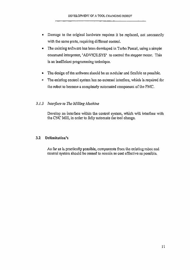
• Damage to the original hardware requires it be replaced, not necessarily
with the same parts, requiring different control.
• The existing software has been developed in Turbo Pascal, using a simple
command interpreter, ‘ADVICE.SYS’ to control the stepper motor. This
is an inefficient programming technique.
• The design o f the software should be as modular and flexible as possible,
o The existing control system has no external interface, which is required for
the robot to become a completely automated component o f the FMC.
3.1.3 Interface to The M illing Machine
Develop an interface within the control system, which will interface with the CNC Mill, in order to fully automate the tool change.
3.2 Delimitation’s
As far as is practically possible, components from the existing robot and control system should be reused to remain as cost effective as possible.
11

DEVELOPMENT OF A TOOL CHANGING ROBOT
4 EXISTING EQ UIP MEN T
Since being built in 1991, the condition o f the robot deteriorated to the
extent that it was completely unusable due to numerous components being
either damaged or lost.
4.1 PC Controller
There is an existing 286 AT PC used for control o f the robot. It is fully
functional other than losing BIOS settings as the internal battery no longer
functions. This PC is suitable for simple control in a DOS environment
using either Turbo Pascal or C to develop the software.
4.2 Stepper Motor and Controller
Rotational actuation o f the robot arm is via a stepper motor (type HY3450-
350-A8). The control o f this motor is by a PCL-838 dedicated PC control
card, which generates one digital pulse for each step o f the motor. A
terminate and stay resident (TSR) software driver, ‘PCL-S3S.EXE’ which
is independent o f the programming language, can be used to program low
level instructions via common programming languages, giving simple but
precise control o f the stepper motor. The PCL-838 card also has three 8-
Bit input and output ports which can be used for other control purposes.
The stepper motor driver, type SD-12, has been damaged to the extent that
it no longer provided accurate control, and therefore required replacement.
4.3 Relay Control Card
In 1994, the original PCLD-7S5 PC Relay control board was damaged.
12

DEVELOPMENT OF A TOOL CH ..NGING ROBOT
4.4 Mechanical Structure
The mechanical components of the arm were complete. While standing
unused it had become dirty with minor corrosion o f the i 'de shafts.
4.5 Instrumentation
All solenoid valves are still functioning, but the wiring L damaged and
untidy and required replacement. None o f the position sensors originally
used were still in existence, and required replacement.
13

DEVELOPMENT OF A TOOL CHANGING ROBOT
5 THE R O B O T C O N T R O L S Y S T E M
5.1 The Original Control System
The original control system was PC based, and incorporated two separate
PC Cards, as depicted in Figure 5.1. The Stepper Motor was controlled
via the PCL-838 Programmable Stepper Motor Driver, while the Solenoid
Valves to actuate the pneumatic cylinders were controlled using a PCLD-
785 Relay Control card which had 16 digital relay outputs. Two feedback
position sensors (reed switches) were also input using the PCLD-7S5 card
which incorporated 16 optically isolated digital inputs.
ROBOTA C T U A T O R
PC
P C L -8 3 8 PCID .785
CNC* M ill
FIGURE 5.1 OVERVIEW OF ORIGIONAL CONTROL SYSTEM
14

DEVELOPMENT OF A TOOL CHANGING ROBOT
As is depicted, there is no control interface with either the environment or
with the milling machine, which is an essential requirement for an
automated tool change.
5.2 Choice of Controller
As the original control system was no longer operable, with damage to the
PCLD-785 relay control card, wiring, and reed switches, the choice o f
controllers for the system was reviewed, and the option o f using a PLC
based control system investigated. A number o f medium priced units are
available for below R2000.
However, these low end PLC’s are not designed for Stepper Motor
applications, which require a pulse to be generated for each rotational step
o f the motor. While PLC’s are capable o f generating a series o f pulses,
they cannot easily cr Urol or vary the number and frequency o f the pulses
to achieve the accurate control, which is possible with the PC based
system. This allows precise control o f the displacement, velocity and
acceleration o f the motor, and hence the robot, in an open loop
configuration.
The SDJ2 Stepper Motor Driver, which is required for either PC or PLC
based control, has an internal pulse generator which could be switched by
a PLC to drive the motor. However this would require the control system
to be modified to closed-loop, incorporating a positional sensor at each
radial position at which the arm may stop.
The PCL-838 stepper motor drive card also includes three 8-bit digital
input ports and three 8-bit digital output ports. There are a number of
adapter relay cards available which can be driven by the PCL-S38’s digital
outputs, and these are significantly cheaper than dedicated PC-based cards
such as the original PCLD-785.
15

DEVELOPMENT OF A TOOL CHANGING ROBOT
For the above reasons, it was decided to remain with the PC based control,
;uu eplace the damaged PCLD-785 card with an electro-mechanical relay
aw pier card which would be driven by the PCL-838 stepper motor card.
For this application, the PC-38 relay adapter unit was chosen.
5.3 Overview of C ontrol System
An overview o f the implemented control system is shown in Figure 5,2
overleaf. As is shown, the only connection to the computer is via the
PCL-S38’s 37-Pin Female D connector, directly to another 37-Pin D
connector on the Main Control Unit. This 37-Pin interface includes the
wiring for the stepper motor, the solenoid valves, the interface with the
Milling Machine and the positional sensors. Wiring diagrams for the 37-
Pin connectors are shown in Figures 5.3 and 5.4 respectively.
16

DEVELOPMENT OF A TOOL CHANGING ROBOT
PC
37 PIN D-PLUG
PCL-838
MAIN CONTROL UNIT
l !
ROBOT
STEPPERMOTOR
STEPPER
i 9 PIN D-PLUG
MECHANICALUNIT
SOLENOIDVALVES
PROXIMITYSWITCH
CNCMILL
FIG U R E 5.2 O V E R V IE W O F T H E IM PL E M E N T E D C O N T R O L SY STEM
17

DEVELOPMENT OF A TOOL CHANGING ROBOT
COMMON (CHI) O l20 O
0 2DIR (CHI)
PULSE0 3
21 O EXT. VCC (CHI)22 O
0 423 O
0 524 O
0 525 O
E. STOP 0 726 O
0 8+ 12V27 0
0928 O + 5V
o 1029 O GND
o n 30 O D /0 0 -V E R TSENSOR 1 -D /1 0 0 1 2 31 0 D/01 - GRIPPERSENSOR 2 - D / l l 013
32 O D/02 - HORIZ INBINARY IN I-D /1 2 014
33 O D /0 3 -H O R IZ OUTBINARY IN 2 -D /1 3 o 15 34 O D /04-R E L E A S E TOOLBINARY IN 4-D /14 O 16
35Q D /05-IN P R O G R E S SR EQ U E ST -D /15 0 17
O IS
0 19
36 O
37 O
FIG U R E 5.3 PCL-838 37 PIN A SSIG N M EN T
18

DEVELOPMENT OF A TOOL CHANGING ROBOT
T A B L E 5.1 PIN A SSIG N M EN TS FO R PCL-838 CARD
TAG PINNo DESCRIPTION
COMM ON 1 Isolated Common for Stepper M otor
PULSE 2 Stepping Pulses for Stepper M otor
DIRN 20 Direction Signal for Stepper M otor
Ext Vcc 21 24 V Power supply from external source (SD-12 Stepper m otor Driver)
E. STOP 7 Emergency Stop for S tepper Motor.
+12 V 27 12 V Output from Computer
+ 5 V 28 5 V Output from Computer
GND 29 PC Ground
SENSOR 1 D/l 0 12 Digital Input 0: Position Sensor for Horizontal Cylinder
SENSOR 2 D/I 1 13 Digital Input 1: Micro Switch to Cheek A nn Down
BINARY 1 D/I 2 14 Digital Input 2: Mill Interface Binary Tool N um ber Digit 1
BINARY 2 D/I 3 15 Digital Input 3: Mill Interface Binary Tool Number D igit 2
BINARY 4 D /l 4 16 Digital Input 4: Mill Interface Binary Tool N um ber Digit 4
REQUEST 17 Digital Input 5: Mill Interface Tool Request
D O 0 VERT 30 Digital Output 0: Control o f Vertical Cylinder Solenoid Valve
D O 1 GRIPPER 31 Digital Output 1: Control o f G rippcr Solenoid Valve
D O 2 HORIZ IN 32 Digital Output 2: Control o f Horizontal In Solenoid Valve
D /0 3 HORIZ OUT 33 Digital Output 3: Control o f Horizontal Out Solenoid Valve
D O 4 RELEASE 34 Digital Output 4: Output to Mill to Release / Clamp Tool Chuck
D O 5 IN PROGRESS 35 Digital Output 5; Output to Mill to Indicate Tool Change in Progress
19

DEVELOPMENT OF A TOOL CHANGING ROBOT
TA B LE 5.1 P 'N A SSIG N M EN TS FO R PCL-838 CARD
TAG PINNo DESCRIPTION
COMMON 1 Isolated Common for Stepper M otor
PULSE 2 Stepping Pulses for Stepper M otor
DIRN 20 Direction Signal for Stepper M otor
Ext Vcc 21 24 V Power supply from external source (SD-12 Stepper m otor Driver)
E. STOP 7 Emergency Stop for S tepper Motor.
+ 12 V 27 12 V Output from Computer
+ 5 V 28 5 V Output from Computer
GND 29 PC Ground
SENSOR 1 D/I 0 12 Digital Input 0: Position Sensor for Horizontal Cylinder
SENSOR 2 D/I 1 13 Digital Input 1: Micro Switch to Check A rm Down
BINARY 1 D/I 2 14 Digital Input 2: Mill Interface Binary Tool Number Digit 1
BINARY 2 D 'l 3 15 Digital Input 3: Mill Interface Binary Tool Number Digit ^
BINARY 4 D/I 4 16 Digital Input 4: Mill Interface Binary Tool Number Digit 4
REQUEST 17 Digital Input 5: Mill Interface Tool Request
D/O 0 VERT 30 Digital Output 0: Control o f Vertical Cylinder Solenoid Valve
D O 1 GRIPPER 31 Digital Output 1; Control o f Grippcr Solenoid Valve
D/O 2 HORIZ IN 32 Digital Output 2: Control o f Horizontal In Solenoid Valve
D/O 3 HORIZ OUT 33 Digital Output 3: Control o f Horizontal Out Solenoid Valve
D/O 4 RELEASE 34 Digital Output 4: Output to Mill to Release / Clamp Tool Chuck
D/O 5 IN PROGRESS 35 Digital Output 5: Outpu. a Mill to Indicate Tool Change in Progress
19

DEVELOPMENT OF A TOOL CHANGING ROBOT
+12V < ------ O ^20 O ------ > EXT Vcc (24V)
+5V <----- O21 O ------ > DIRN
< ----------- . oHORIZONTAL IN <
22 OO
------ >PULSE23 0 ------> COMMON
GRIPPER < ------ O24 O <----- E. STOP
VERTICAL < ------ O25 O <— SENSOR 1
HORIZONTAL OUT < ----- • O26 O « — SEN SO R2
RELEASE < ----- O
T XT27 0 <— BINARY INI
UN° 28 O <---------- BINARY IN2O 10
29 0 < — BINARY IN40 , 1 30 O < — REQUESTO K w o
0 1 332 O
0 1 4 .33 O
0 15 34 O0 16 , ,
35 00 1 7 „
36 O0 1 8 ,
37 O-------------> GROUND
0 1 9 ^ ^ /
F IG U R E 5.4 PIN A SSIG N M E N T F O R M AIN C O N T R O L L E R 37-PIN C O N N E C T O R
20

DEVELOPMENT OF A TOOL CHANGING ROBOT
The Main Control Unit case contains the following items:
• An AC transformer to provide power to the stepper motor driver. This
supplies 26V, 18V, 0, -18V and -26V AC outputs.
® The PC-38 Relay adapter card. The relays are switched from the PCL-
838 digital outputs, and control the solenoid valves as well as a
interface signal to the Milling machine.
• A 24V Relay card, which is used to isolate the 24V output signals from
the Milling machine interface. These are then input into the PCL-838
card.
• The SD-12 Stepper Motor Driver.
Photographs o f the Main Control Unit is shown below in Figure 5.5.
t AC TRANSFORMER
SDl2SraU>t;R MOTOR ORIVT-R ____
PC-38 RELAY AD APTOR CARD
FIGURE 5.5(h) TOP VIEW OF MAIN CONTROL UNIT
21

DEVELOPMENT OF A TOOL CHANGING ROBOT
© o © ® © ®
LEGEND
I 24V POWER SUPPLY
2 STEPPER MOTOR CONNECTOR
3 COMMON EARTH SWITCH
4 SOLENOID CONNED TOR (9-P1N 0 )
5 SENSOR CONNECTOR (W IN D)
6 Mil l INTERLACE CONNECTOR (W IN D'
7 COMPV TV.R CONNECTOR (37-VIN D)
S COOLING I AN
0 220V POWER SUPPLY
10 POWER SWITCH
FIG U R E 5.5 (b) M AIN C O N T R O L UN IT
As is shown in Figure 5.5 (b), the Main Control Unit provides plug in
connections for the stepper motor, the position sensors, the solenoid valves
and the milling machine interface. The box is enclosed with clear acrylic
to prevent dirt ingrcssion, A cooling fan has also been included to remove
the heat generated by the transformer.o n

DEVELOPMENT OF A TOOL CHANCING ROBOT
5.4 Interface with the CNC Mill
Following consultation with Dana Maas (1998) of Unimation CC, the
agents for the CNC Milling Machine, a standard for the interface was
developed, using a 9-Pin RS connector. The signal voltage is 24V.
When a tool change is required, the ‘Tool Request’ output from the CNC
becomes live, and a 3 bit binary number representing the tool number is
sent. At this stage, the Robot will make the ‘Toolchange Done’ output
OV, indicating the change is in progress.
When the tool must be clamped or undamped, a one second pulse is sent
on the ‘Tool Unclamp’ Output from the Robot, which will activate the
relay on the CNC Mill tool chuck. When the tool change is complete, the
‘Toolchange Done' Output becomes live again, and the robot will proceed
The pin assignment is as follows:
CNC to Robot:
Pin 1 Binary Bit 1
Pin 2 Binary Bit 2
Pin 3 Binary Bit 4
Pin 4 Tool Request
Robot to CNC:Pin 5: Tool change in progress
Pin 6: Tool Unclamp
Pin?: OV
A quotation for the modifications (a software upgrade and the wiring up of
the 9-Pin RS connector) bos been obtained, and is included in Appendix C.
However, due to time constraints, this has not been implemented,
23

DEVELOPMENT OF A TOOL CHANGING ROBOT
In order to proceed with testing o f the Robot, a manual control box has
been built to simulate the CNC Mill. The test box includes six buttons,
and when pressed, sends a binary signal to the Robot to indicate the
requested tool number. The test box also has two lights, which represent
the ‘Tool change complete’ and ‘Tool Unclamp’ outputs from the Robot.
5.5 Replacem ent of Sensors
In order to facilitate greater operational flexibility, two positional sensors
have been incorporated in the new design. Both are optional, and can be
disabled in the software settings. This is discussed in the following
chapter.
The first sensor (connected to the SENSOR 1 input on the PCL-838 card)
is a reed switch connected to the horizontal cylinder on the arm. This is
used to position the arm in a mid position by switching the air supply to
the cylinder off when the input becomes positive. The position o f the
sensor can be adjusted along the length o f the horizontal cylinder, allowing
the grippcr extension at this state to be adjusted. This is useful to allow
the position o f the robot relative to the Mill to be adjusted.
The second sensor (connected to the SENSOR 2 input on the PCL-838
card) is a micro switch, which is used to check the arm had returned to a
down position after the tool has been removed from the Mill chuck. This
is necessary as the tool tends to get stuck in the chuck.. Should this occur,
the limit switch will not be made, and the robot will not proceed with the
remainder o f the sequence, but will give an audible beep from the
computer speaker, which repeats every couple o f seconds until the
problem is resolved.
24

DEVELOPMENT OF A TOOL CHANGING ROBOT
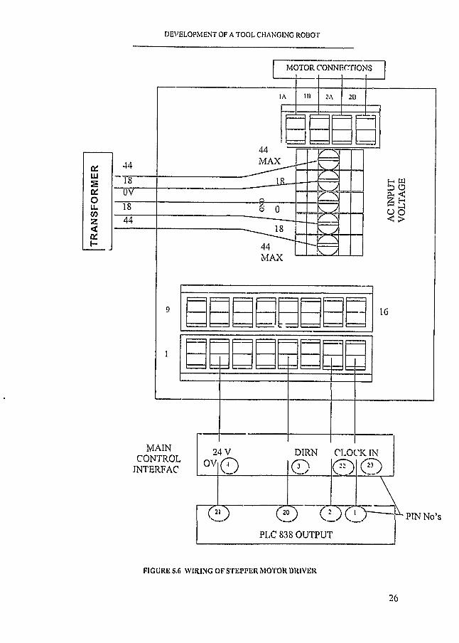
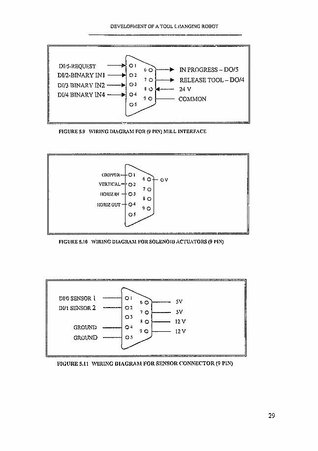
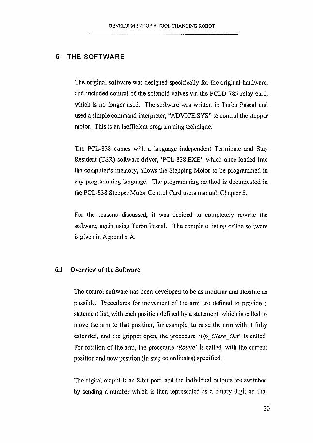
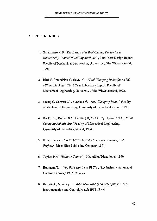
5.6 Wiring of the Main Control Unit
The Main Control Unit is hard wired to allow the Mill, Solenoids and
Sensors to plug in using standard RS 9-Pin D plugs. All wiring internal to
the unit is fully tagged for quick identification. Wiring Diagrams are
presented below for the following:
• The SD-12 Stepper Motor Driver (Figure 5.6)
• The PC-38 Relay card (Figure 5.7)
e The 24V Relay Card (Figure 5.8)
• 9-Pin D Connector to Mill Interface (Figure 5.9)
» 9-Pin D Connector to Solenoid Valves (Figure 5.10)
• 9-Pin D Connector to Position Sensors (Figure 5,11)
25
TR
AN
SF
OR
ME
R
DEVELOPMENT OF A TOOL CHANGING ROBOT
MOTOR CONNECTIONS
MAX
OV
MAX
MAINCONTROL
INTERFAC
24 V DIRN CLOCK INOV
PIN No’s
PLC 838 OUTPUT
FIGURE S.6 W IRING OF STEPPER MOTOR DRIVER
26

DEVELOPMENT OF A TOOL CHANGING ROBOT
FROM PCL-838 37 FIND
TO SOLENOIDS TO
1 >§ 5
S z ss > S
© © © © © © © O '- .PINNos
O O O G O O O G1 PC 38 RELAY CARD(SEE APPENDIX FOR CIRCUIT
DIAGRAM
AO A t A2 A3 A4 A5
N( c No N r c |n 0 N clC No Nr C No NC C No N c C NoA A A A A A
X IE D
±
ED ±
t-24
X+24
HO
RIZ
IN
GR
IPPE
RO
PEN
VE
RT
ICA
L
HO
RIZ
OU
T
SOLENOID VALVES
+ 24 +24
lO~o -
M IL L IN T E R FA C E
FIGURE 5.7 PC-38 COM PUTER RELAY ADAPTER CARD
27
CLAM
P PR
OG
RES
S TO
OL

DEVELOPMENT OF A TOOL CHANGING ROBOT
FROM MILL 9-PIN D- PLUG
oMill ground
Rz relayNC -• normally closed C - common No - normally open
24V relay cord
Nc C No
" = '• < — Computer ground
PIN MAIN CONTROL!,
PCL-838 37 PIN D-PLUG
FIGURE 5.8 WIRING DIAGRAM FOR 24 V RELAY CARD
28
DEVELOPMENT OF A TOOL C HANGING ROBOT
DI/5-REQUEST -------- ►
DI/2-BINARY I N I M
DI/3 BINARY IN 2 ------- ►DIM BINARY IN 4 ------- ►
o I 0 2
0 3
0 4
0 5
6 O
7 O
8 O9 O
► IN PROGRESS-DO/5
-> RELEASE TOOL-DOM— 24 V
— COMMON
F IG U R E 5.9 W IR IN G D IA G R A M F O R (9 PIN) M IL L IN T ER FA C E
GRIPPER— - O l
VERTICAL— 0 2OV
HORIZ IN - - 0 3
HORIZ OUT - - 0 4
05
F IG U R E 5.10 W IR IN G DIA G R A M FO R SO L E N O ID A C TU A TO R S (9 PIN)
DI/O SENSOR 1
DI/1 SENSOR 2
GROUND
GROUND
O l6 O
0 27 O
0 38 O
0 49 O
0 5
5V
5V
12 V
12 V
FIG URE S .l l W IRING DIAGRAM FO R SENSOR C ON NECTO R (9 PIN)
29
DEVELOPMENT OF A TOOL CHANGING ROBOT
6 THE S O F T W A R E
The original software was designed specifically for the original hardware,
and included control o f the solenoid valves via the PCLD-785 relay card,
which is no longer used. The software was written in Turbo Pascal and
used a simple command interpreter, “ADVICE.SYS” to control the stepper
motor. This is an inefficient programming technique.
The PCL-838 comes with a language independent Terminate and Stay
Resident (TSR) software driver, ‘PCL-83S.EXE’, which once loaded into
the computer’s memory, allows the Stepping Motor to be programmed in
any programming language. The programming method is documented in
the PCL-838 Stepper Motor Control Card users manual: Chapter 5.
For the reasons discussed, it was decided to completely rewrite the
software, again using Turbo Pascal. The complete listing o f the software
is given in Appendix A.
6.1 Overview of the Software
The control software has been developed to be as modular and flexible as
possible, Procedures for movement o f the arm are defined to provide a
statement list, with each position defined by a statement, which is called to
move the arm to that position, for example, to raise the arm with it fully
extended, and the grippcr open, the procedure 'U j^C losc^O ut' is called,
For rotation o f the arm, the procedure 'Rotate' is called, with the current
position and new position (in step co ordinates) specified.
The digital output is an 8-bit port, and the individual outputs are switched
by sending a number which is then represented as a binary digit on tha.
30

DEVELOPMENT O f A TOOL CHANGING ROBOT
port. By way o f illustration, the binary code for the number 9 is
00001001, so the first and fourth output would be switched on (last binary
digit represents the first digital output, and each subsequent digit the next
output). Each solenoid valve is controlled via a single digital output.
Therefore, the value o f the output designated which solenoid valves will
be switched. Similarly, for the digital inputs, the computer is reading a
number which when represented as an 8-bit binary number, specifies
which inputs are on and which are not.
The software has also been designed to allow any control settings to be
adjusted in a SETTINGS menu. From this the menu, the home position o f
each o f the tools can be adjusted (Positions are specified in Degrees), as
well as the angular position o f the Mill. Other variables that can be
adjusted include the rotational speed and acceleration o f the arm, the pause
time delay between movements to allow a movement to be completed.
The ‘SETTINGS’ menu also provides the option o f enabling or disabling
the two sensors. The first sensor allows the extension o f the arm to be
limited to a mid position which is adjustable by positioning the reed switch
at the appropriate position on the horizontal cylinder, This is useful
should the robot be positioned such that Mill Chuck is not located at the
correct distance for full extension o f the grippcr,
The second sensor checks that the arm had moved down after retrieving a
tool to ensure that the tool has not become stuck in the milling machine
chuck, which is a common problem. I f this function is enabled from the
software and the tool becomes stuck, the robots motion is halted and an
audible beep is repeatedly sounded until the problem is resolved,
31

DEVEl OPMENT OF A TOOL CHANGING ROBOT
6.2 Operating the Software
Operation o f the software is extremely simple. The program is initiated by
typing ‘ROBOTX’ (if necessary the computer drive assignment and / or
root directory where the software is located may be needed). The software
takes a few seconds to initiate. From there, on screen prompts specify the
options which are available. Validity and range checking is provided for
all inputs to ensure stability o f the software and prevent the system
crashing due to a user error.
6.3 Detailed Description of Software Procedures
A description o f each procedure in the software if described below:
Welcome This procedure initiates the welcome screen when the
software is run. The user is given the option of
varying the software settings (see procedure
GetJSettings below). The user is also offered the
option o f running the manual test program (sec Test
below).
Base_Active This procedure initiated control o f the PCL-838 driver
card by loading the software driver into the computer
memory.
Clteckl Ensures that the software driver ‘PCL-838,EXE’ is
correctly loaded into the computer memory
32

DEVELOPMENT OF A TOOL CHANGING ROBOT
GetJSettings
ChangeJSettings
This procedure reads the data stored in the file
‘SETTINGS.DAT’ into the computer memory. This
file contains data which is used to adjust the control
and functions o f the robot. It includes the following:
• variables which describe the radial position o f the
mill chuck, each tool in the tool holder and the
‘home’ position o f the arm (in degrees). Any of
these can be adjusted, to cater for mechanical or
positional adjustments o f the robot and tool holder.
• the acceleration rate and maximum speed o f the
stepper motor.
• variables which allow the user to select if either o f
the two position sensors are to be used (as detailed
in section 5.5).
• a variable which allows the user to specify i f the
robot is going to controlled automatically from the
mill CNC interface, or via a manual user input
using the PC keyboard.
I f the software cannot find the file 'SETTINGS,DAT’,
which would be the case the first time the software is
run on a different computer, a new file is created.
This procedure is called by the software if the user
selects the option o f changing the settings from the
Welcome menu, When called, it allows any o f the
variables stored in the file ‘SETTINGS,DAT’ to be
changed, and the new values are re-written into the file
SETTINGS.EXE, Range checking is performed at
each stage to ensure only valid values for each
parameter are entered, Should a value outside the
33

DEVELOPMENT OF A TOOL CHANGING ROBOT
specified range be entered, the software requires the
user to re-enter the value until a valid value in entered.
The software also allows either lower- or upper case
character inputs.
Test This procedure allows the user to test simple individual
movements o f the arm from a menu on the screen,
using keyboard inputs.
Waiting This sends an output to the mill, which indicates that
the robot is idle. When a tool change is in progress,
this output is low (off), and becomes high again once
the tool change is complete, indicating the mill can
continue with it’s routine.
ClampJUnclamp Sends an output to the mill for one (1) second to
activate the relay which releases the hydraulic tool
chuck. This is required to both release and clamp the
tool.
Check_Arm_Down This procedure is only called if the vertical position
sensor is turned on from the Settings menu. It checks
that the arm has returned to the down position after a
tool is retrieved from the mill chuck. If this does not
happen, the robot sequence is delayed and an audible
beep is sounded repeatedly until the problem is
resolved.
Tool_Number This procedure reads in the new tool number from
either the mill interface, or from a manual input into
the PC keyboard, depending on the configuration of
the software in the Settings menu.
34

DEVELOPMENT OF A TOOL CHANGING ROBOT
Full range checking is performed to ensure that only a
valid tool number is input.
Delay Creates a pause in the robot’s motion, the length o f
which is specified in milliseconds.
Rotate This procedure controls the stepper motor in order to
rotate the robot arm from it’s current position to a new
position, as specified by the variable 'm w jp o s '. The
arm is accelerated from rest to its maximum speed over
a specified time, which is stored the
‘SETTINGS.DAT’ file and can be adjusted. The arm
then rotates at constant speed until close to its new
position before decelerating at a rate equal to the initial
acceleration. This is to avoid unnecessary stress on the
motor. The radial position o f the arm at all times is
stored in the variable 'current_pos\
D omi_Close_In; Dowii_Close_Out; D om i_Open_In; D ow njO pcnjO ut;
Up_ClosemIns Up_Close_mOut; Up_Open_Iu; Up_Opcn_Out
These procedures form a statement list, which is used
later in the software. Each describes a position o f the
arm. By calling the procedure ‘ Up_Opcn_In \ the
arms position would move such that it was in an up
position with the grippcr retracted and open. Each
procedure sends a binary output to the solenoid valves
which control the cylinders, which corresponds to a
position o f the arm as described in Table 6.1.
35

DEVELOPMENT OF A TOOL CHANGING ROBOT
Down_Close_Half; Up_Close_Half; Down_Open_half; Up_Open_Ha!f
As above, these procedures form a statement list, each
describing a position o f the arm, which is used by the
rest o f the software. However these procedures are
only called if the option to use the reed switch on the
horizontal cylinder is specified in the Settings menu, If
this is the case, the horizontal extension o f the arm is
controlled to a position determined by the position o f
the reed switch on the cylinder. This can be adjusted
to allow any amount o f horizontal extension when
putting a tool in the mill chuck.
G ctjC unentJTool This procedure uses the above described procedures to
retrieve whichever tool is currently in use in the mill
(as stored in the variable ‘curren tJoo l ') and return it
to it’s correct location in the tool holder once a valid
tool change has been requested.
Put_New_Tool This procedure uses the above described procedures to
retrieve whichever new tool is requested during a tool
change from the tool holder, and place it in the mill
chuck before returning the robot arm to the home
position.
36

DEVELOPMENT OF A TOOL CHANGING ROBOT
Tabic 6.1 Robot Positions Corresponding to Binary Outputs
ROBOT ARM POSITION BINARYVALUE
DECIMALVALUE
Down_Close_ln 0100 4
Up_CloseJn 0101 5
DownJDpenJn 0110 6
UpjD penJn 0111 7
Down_Close_Out 1000 8
Up_Close_Out 1001 9
Down_Open_Out 1010 10
Up_Open_Out 1011 11
37

DEVELOPMENT OF A TOOL CHANGING ROBOT
Run Manual Test ProgramDisplay ll'eteome screen.
Check there is a tool in use tool
Cheek new tool isn't the same as the current tool
Load software Driver PCL-838 into memory and check
Load 'SETTINGS DA 7" Vile
Position robot arm in home position
Send output to Mill to indicate tool change in progress
Fetch Current tool ftom Mill and return it to tool holder
Run Settings Procedure to adjust Variable Settings
Position robot arm in home position
Fetch new Tool from tool holder and place in Mill Chuck
Send output to Mill to indicate tool change complete
Run Manual Test Program
Run 1 Too/j\'iim bcr' procedure until valid tool No is input from mill, or lire user enters an 'S ’ or
an "X'
Figure d.l Flow D iagram for M ain Software Sequence
38

DEVELOPMENT OF A TOOL CHANGING ROBOT
7 MECHANI CAL MODI FI CATI ONS
Mechanically, the robot was complete and fully functional. For
completeness o f this report, a set o f assembly and component drawings has
been produced and is presented in Appendix B.
However, there was no stand to mount the robot in position to perform a
tool change on the Milling machine. A problem was also experienced
with the position and alignment o f the tool holder, as the original stand
was not well constructed and offered little adjustment for the tool holder.
A new stand for the robot was built which consists o f a simple rectangular
frame, made from 38x38x2 mild steel tube, mounted on the floor, which
positions the robot at the correct height to perform a tool change. This is
shown in Figure 7.1.
The tool stand support frame was also re-built to allow for adjustability
and greater stability, while still being a far simpler construction. This is
shown in Figure 7.3
A limiting collar was also placed on each o f the two 20mm horizontal
guide shafts to restrict the maximum reach o f the arm and prevent it from
hitting the tool holder when extended. Boakes et al (1994) documented
problem = with the arm shooting out too fast m il proposed a number of
methods to overcome this, concluding that the most feasible option would
be to pulse the air supply to the cylinder by switching the solenoid valve.
Ho vever this problem was easily overcome by using the air flow
rcstrictcr, thereby slowing the flow o f air into the cylinder, and hence
reducing the velocity o f the grippcr.
39

L I N E A R B E A R I N G S — v
H O R I Z O N T A L G U I D E S — \ H O R I Z O N T A L S U P P O R T F R A M E - — ,
G R I P P E R A S S E M B L Y
C Y L I N D E R F E S T O D S N N - 1 6 - 2 0 0 P P V A
I N E / ' R S E A R I N G S
C L Y L I N O E RF E S T OD S N - 2 5 - 1 6 0 - 1
- P R O T R A C T O R - - F E S T O P R E S S U R E
R E G U L A T O RE R T I C A L G U I D E S
R T I C A L S U P P O R T — ' AME
G U I D E ^ T O P -
V E R T I C A L S H A F T -
M A I N S U P P O R T FRAMES T E P P E R MOTOR & G E AR B O X
E L E V A R O B O T I C ARM T OOL S E L E C T O R
T IT .E --R!
T i
r o b o t . d g n l i a r . 23, 1935 15 :0 7 :49
DRAW N
S C f i E

TOOL L O C A T O R
TOOL H OL D E R
C Y L I N D E R F E S T O D S N N - 1 6 - 2 0 0 P P V A
T OOL S U P P O R T FRAME
— P R O T R A C T O R -— F E S T O P R E S S U R E
R E G U L A T O R
M A I N S U P P O R T FRAME
A T I O N ON R O B O T I C ARIVl T O O L S E L E C T O R
t i t l e . R O B O T I C ARIVl T O O L S E L E C T O R
DRAW N
SCALE 1 : 5d r g . n o F | G U R E Yu1 R E V

640
ooST
9 0 0
3 0 0
P L A N
9 0 03 0 0
T Y P I C A L U . N . O .(N
" HK. C H I P B O A R D S H E L F
E L E V A T I O N R O B O T S U P P O R T F R A M E
T O L E R A N C E 0 . 5 UNO
T IT L E :
R OBO R O B O T SU
DRAW N
S C A L E 1 : 7 . 5o b o t . d g n Mar, 23, 1998 17:2d: 10

9 0 0
- = — = =_= - Vitiiiiiiiiiiiiiiiiiiii
= — =====' \rrI
f-I P L A N
I _ _ 9 0 0
3 0 0
3 0 0
3 8 X 3 8 X 2 S H S T Y P I C A L U . N . O .
8 S O . BAR ^
[ V A T I O N R O B O T S U P P O R T F R A M E
T O L E R A N C E
C H I P B O A R D S H E L F
0 . 5 UNO
TITLE'-
R O B O T I C ARMR O B O T S U P P O R T F R A M E
DRAW N D R G . N O . R E V
S C A L E 1 : 7 . 5 F I G U R E 7 .2

003Z00
OnJ
X
CM
X
L OC \J
LOh-m
O-rn
E L E V A T I O N ON T O O L H O L D E R S U P P O R T3 - R E Q ' D AS DRAWN
2 - 0 8 H O L E S
un
oro
5 0
E N D V I E W
ALL D I M E N S I O N S 0 . 2
T IT L E : ROn
S U PDRAWN
SC A L E
e :X d g n ^ o t io t .o g n Mar, 23, 1909 16:3 4 :27

y
25
- -
50
- L A N
(/)znuiCM
X
LT)( X I
X
in<NI
IDr-'V ,
o lro i
0 8 H O L E S
oro
1 2 . 5
T O O L H O L D E R S U P P O R T( E Q ' D AS DRAWM
25
L O
1 2 . 550
E N D V I E W
T IT LE: R O B O T I " ARM T O O L H O L D E R
S U P P O R T F R A M EA LL D I M E N S I O N S ± 0 . 2 DRAW N I ™ FIGURE 7.3
R E V
S C A L E 1 : 5

DEVELOPMENT OF A TOOL CHANGING ROBOT
C O N C L U S I O N
The Tool Change Robot has been modified substantially, particularly the
control system, to make it operational again and to incorporate an interface
with the environment.
The damaged PCLD-785 Relay Control Card has been replaced with a PC-
38 Relay Adapter card, which is switched by the digital outputs from the
PCL-S3S Stepper Motor Driver. Ail Electronic hardware external to the
computer has been built into the Main Control Unit, which is connected to
the PC via a single cable with 37-Pin D-type conncctors. The main
Control Unit has been hard wired to provide plugs for all auxiliary
equipment to connect easily to it.
All software has been re-developed to improve the functionality.
Procedures are used to define a statement list o f all positions for the robot
arm which can be simply called. The software also makes provision for
many control variables, such as the position o f each tool, and the
maximum speed o f rotation, to be adjusted and stored permanently in a
separate file. The software also allows for either the CMC Mill interface
to be used, or the user to select the new tool from the PC Keyboard.
The software has also been developed to be stable, and provides range
checking o f all inputs, and requires the user to re enter any value which is
incorrectly entered. It also incorporates a simple test option which allows
individual movement procedures, such as rotation o f the arm to a specific
position, to be tested individually using only keyboard inputs.
The new control system also includes two optional sensors, which can be
switched o ff from the ‘SETTINGS' menu in the main program, The first
is used to control the extension o f the arm and limit it to a mid position if
43

DEVELOPMENT OF A TOOL CHANGING ROBOT
required, and the second provides a check that the arm has lowered after
retrieving a tool from the mill, to ensure no damage occurs if the tool
becomes stuck in the mill chuck.
An interface to the CNC has been developed with the agents for the CNC
Mill and this has been incorporated into the Robot. However,
modifications are still required on the CNC Mill for the interface.
However, a manual control unit has been built to simulate the CNC
interface for testing purposes. This manual control unit plugs into the 9
pin mill interface plug (Figure 5.9)
A stand had also been built for the Robot to position it correctly to perform
a tool change on the Mill. The Tool Holder support has also been re-built
more simply but to allow better adjustment o f the Tool Holder and
increase rigidity.
The robot has been completely tested and all components are completely
operational. This was demonstrated to M r E Fielding, the project
supervisor from the Department o f Industrial Engineering. During the
demonstration, the robot performed a number o f complete tool changes on
the milling machine while using the manual control unit to simulate the
Mill interface.
44

DI V I I O l ’MI M O! A I ( ) ( ) I CIIANCHNCi R O B O I
FIG URE 8.1 OVERVIEW O F ROBOT
FIGURE 8.2 ROBOT ARM EXTENDED TO RETRIEVE TOOL FROM MILL
45

DEVELOPMENT OF A TOOL CHANGING ROBOT
9 F U R T H E R WO R K REQUI RED
The robot meets all the requirements and is capable o f performing a
completely automated tool change. However the following two items
should still be addressed:
1. The modifications to the CNC Mill should be implemented. A quote is
included in Appendix C, and includes the scope o f work required.
2. There is currently no way o f rotating the Milling Machine chuck to a
standard position during the tool change. This is necessary, as when a
tool must be put into the chuck, the driving lugs on the chuck must be
aligned with the key ways on the tool for it to fit. This problem is
discussed by Chang et al (1993) and again by Boake et al (1994).
They conclude that this can be addressed by placing a proximity
switch on the clutch spindle, and writing a routine in the CNC software
which would rotate the spindle at the lowest RPM, 40, until the sensor
is made and the spindle would be stopped. To implement this, the
agents for the CNC would be required to implement the change to wire
the sensor input into the CNC controller.
4 6
DEVELOPMENT OF A TOOL CHANGING ROBOT
10 R E F E R E N C E S
1. Smargiasso M.F 'The Design o f a Tool Change Device fo r a
Numerically Controlled Milling M achine' , Final Year Design Report,
Faculty o f Mechanical Engineering, University o f the Witwatersrand,
1991.
2. Bird V, Comodakes C, Hayti G, ‘Tool Changing Robot fo r an NC
Milling Machine ’ Third Year Laboratory Report, Faculty o f
Mechanical Engineering, University o f the Witwatersrand, 1992.
3. Chang C, Corsaro L.F, Svoboda V, 'Tool-Changing R o b o t Faculty
o f Mechanical Engineering, University o f the Witwatersrand, 1993.
4. Boake T.S, Buldeii S.M, Henning D, McCaffrey D, Smith S.A, 'Tool
Changing Robotic A n n ' Faculty o f Mechanical Engineering,
University o f the Witwatersrand, 1994.
5. Fuller, James L 'ROBOTICS. Introduction, Programming, and
Projects' Macmillan Publishing Company 1991.
6. Taylor, P.M 'Robotic Control', Macmillan Educational, 1990.
7. Hohmann T, 'W hy P C s won't kill P IC 's \ S. A Instrunn ntation and
Control, February 1997 : 72 - 75
8. Barwise C, Moodley J, 'Take advantage o f control options' S.A
Instrumentation and Control, March 1998 :2 - 4.
47

DEVELOPMENT OF A TOOL CHANGING ROBOT
9. Maas, D. Unimation CC (tel O il- 845-3278). Verbal Consultation
concerning interface to CNC Milling Machine.
10. lPCL-S3S Stepping Motor Control Card Users Manual', Advantech
Co, 1992
48

DEVELOPMENT OF A TOOL CHANG''-.’C, f ' •v;f> r
A P P E N D I X A
PRIN TO U T O F TH E SOFTW ARE

DEVELOPMENT OF A TOOL CHANGING ROBOT
{$111 8000,0,0}
PROGRAM ROBOT;
{CONTROL SOFTWARE FOR THE CNC MILL TOOL CHANGE
ROBOT}
{TH IS PROGHM! USES THE TSR SOFTWARE D RIVER, 'P C L -8 3 8 .E X E '
USES
d o s , c r t ;
CONST
{SETTING UP a PARAMETER TABLE FOR REFERENCE B Y P C L -8 3 8 DRIVER}
_ c h l = $ 0 0 0 1 ;
_ c w l = $ 0 0 0 0 ;
_ c c w l = $ 0 1 0 0 ;
C M D _ S e tT im e = 1 ;
C M D _ S e t S t e p = 2 ;
C M U _ S e t V e l o c i t y = 3 ;
C M D _ A c t iv e = 1 0 ;
C M D _ T r . i n s £ e r = 1 1 ;
CMD_Run v 1 2 ;
C M D _ P au se = 1 3 ;
C M D _ C o n t i n u e = 1 4 ;
C M D _Rem ain - 1 5 ;
C M D _F re e = 1 6 ;
CM D_H0ld = 1 7 ;
CM D_Lrop = 1 8 ;
CM D_Skcp = 1 9 ;
CMD_LoopNo = 2 0 ;

DEVELOPMENT OF A TOOL CHANGING ROBOT
C M D _ O u tp u t = 3 0 ;
C M D _ I n p u t = 3 1 ;
C M D _ D elay = 4 2 ;
C M D _ W rig h t = 5 0 ;
CMD_Read = 5 1 ;
CM D_Base = 5 3 ;
C M D _ R e s e t = 5 4 ;
C H D _ S e t T i m e r = 5 5 ;
C M D _ W a i tT im e r = 5 6 ;
CM D _R em ainLp = 5 8 ;
CMD—C l e a r = 5 9 ;
CM D_CwStep = 6 0 ;
C M D _C cw Step = 6 1 ;
C M D _ S te p S p d = 6 2 ;
C M D _S low Tim e = 6 3 ;
C M D ^ S lo w S te p = 6 4 ;
CMD—S l o w V e l o c i t y = 6 5 ;
CM D_SlowDown = 6 6 ;
CMD—C w S p e e d = 6 7 ;
CM D _Ccw Speed = 6 8 ;
G M D _ S c t S t a r t = 6 9 ;
C M D _ G e t I n d e x = 7 0 ;
C M D _ I n d n d e x = 7 1 ;
CM D_Buay = 7 2 ?
5 !

DEVELOPMENT OF A TOOL CHANGING ROBOT
F i l e N a m e = ' b : s e t t i n g s . d a t 1 ; {NAME OF DATA SETTIN G S F IL E }
S t e p s _ p e r _ D e g r e e : INTEGER = 7 0 ; (NO OF STEPS OF MOTOR PER){DEGREE}
TYPE
{DECLARATION OF TABLE FOR CONTROL OF REG ISTERS FOR P C L -8 3 8 DRIVER}
F u n T a b l e = RECORD
f u n N o : INTEGER;C h a n n e l : INTEGER; b u f f e r : ABYTE; v i . v f : INTEGER; t i m e , s t e p : L O N G IN t ; d a t a ; INTEGER; r e t u r n V a l u e : LONGINT
END; {OF RECORD DECLARATION}
{DECLARATION OF RECORD WHICH WILL CONTAIN CONTROL SETTIN G S FOR ROBOT}
S e t t i n g s = RECORD
T o o l l _ p o s ,T o o l 2 _ p o s ,T o o l 3 _ p o s ,
T o o l 4 _ p o s ,T o o l 5 _ p o s ,T o o l 6 _ p o s : INTEGER;
B a s e , M i l l : INTEGER;
A c c _ S t e p s ,M a x _ S p e e d , P a u s e _ T i m e : I n p u t _ M e t h o d • INTEGER; M i l l _ I x t : INTEGER; V e r t _ S e n s o r : CHAR;
END;
VAR
{DECLARATION OF GLOBAL VARIABLES FOR SOFTWARE}
r e g s : R e g i s t e r s ; t a b l e ; F u n T a b l e ;S e t t : S e t t i n g s ;C u r r e n t _ p o s : INTEGER; {CUTTENT ROTATIONAL P O SITIO N Of ' \ m jC u r r e n t _ T o o l : INTEGER; (NUMBER OF TOOL I N USE}
{P O SITIO N OF TOOLS I N DEGREES}
{P O SITIO N OF BASESM ILL I N DEGREES}
INTEGER; {SPEED CONTROL SE TTIN G S}{KEYBOARD OR M ILL INTERFACE INPUT} {M ILL A T FULL OR HALF EXTENSION} {FOR A SENSOR ON VERTICAL CYLINDER}

DEVELOPMENT OF A TOOL CHANGING ROBOT
N e w _ T o o l i INTEGER; {NUMBER OF NEW TOOL}T o o l _ P o s : ARRAY[ 1 . . 6 ] O f INTEGER; {ARRAY STORING THE RAD IAL
LOCATION OF TOOLS)
B a s e _ P o s ,M i l l _ P o s : IN TE G ER / {RADIAL LOCATION OF BASE AND M ILL I N STE P S)
C u r r e n t _ 0 u t p u t _ 0 : INTEGER; {CURRENT OUTPUT VALUE OF PORT 0}
H a l f _ O u t _ T e s t : BOOLEAN; {TE ST I F ARM I N MID P O SITIO N )S e t t i n g F i l e : F I L E OF S e t t i n g s ; {F IL E CONTAINING ALL}
{ADJUSTABLE SE TTIN G S)
E x i t _ V a r : CHAR; fTERMINATE PROGRAM I F 'X ' I S ){ENTERED}
PROCEDURE G e t _ S e t t i n g s ?
{T H IS PROCEDURE READS THE VARIABLE CONTROL SETTIN G S FROM THE F IL E } { ' S E T T IN G S .D A T ')
{ IF THE F IL E D O ESN 'T E X IS T , I T CREATES I T WITH STANDARD SE TTIN G S)
BEGIN
A S S I G N ( S e t t i n g F i l e , F i l e N a m e ) ;{ $ ! - )
R e s e t ( S e t t i n g F i l e ) ;{ $ i + }I F l o R e s u l t <> 0 THEN {CHECKS FOR
{WHICH WILL {E X IS T . I F {A NEW F ILE
BEGIN
S e t t . T o o l l _ p o s := - 3 0 ;S e t t , T o o l 2 _ p o s := - 1 8 ;S e t t . T o o l 3 _ p o s := - 6 ;S e t t . T o o l 4 _ p o s := 6 ;S e t t . T o o l 5 _ p o s := 1 0 ;S e t t . T o o l 6 _ _ p o s : = 3 0 ;
S e t t . M i l l := 9 0 ;S e t t . B a s e := 0 ;S e t t . A c c _ S t e p s ;= 2 0 0 ;S e t t . M a x _ S p e e d := 1 0 0 0 ;S e t t . P a u a e _ T i m e := 3 0 0 0 ;S e t t . I n p u t _ M e t h o d := 1 ;S e t t . M i l l _ E x t := 1 ;S e t t . V e r t _ S e n s o r := ' N ' ;
R E W R I T E ( S e t t i n g F i l e ) ;W R I T E ( S e t t i n g F i l e , S e t t ) ;
END
53
{TURN OFF ERROR CHECHING)
AN ERROR I N OPENING F I L E ,} OCCUR I F THE F IL E DOES NOT) THERE I S AN ERROR, )I S CREATED)

DEVELOPMENT OF A TOOL CHANGING ROBOT
ELSER E A D ( S e t t i n g F i l e , S e t t ) ;
F IL E }
C L O S E ( S e t t i n g F i l e ) ;END;
{READING DATA I N SETTINGS
PROCEDURE C h n n g e _ S e t t i n g s ;
{TH IS PROCEDURE I S USED TO CHM’tSGE THE DATA I N THE F IL E ' SE TTIN G S. D A T'}
VAR
T e s t l : BOOLEAN; {TE STS INPUT FOR 'X ' TO E X IT LOOP}T e m p i : STR IN G ; {TEMPORARY STORAGE FOR NEW VARIABLE INPUT}T e m p 2 , e r r : INTEGER; {USED I N CHECKING V A L ID IT Y OF DATA}
BEGIN
REPEAT T e s t l := F a l s e ; C l r S c r ;
{CONTINUOUS LOOP UNTIL AN 'X ' I S ENTERED}
W RITELN( 1 S E T T IN G S 1) ;
WRITELN; WRITELN;W RITELN( 1 CURRENT SETTINGS 1) ;WRITELN;WR ITELN( ’ E n t e r N u m b e r T o C h a n g e S e t t i n g ' ) ;WRITELN;W RITELN( 1A . Home P o s i t i o n :
, S e t t . B a s e ) ;W R IT E L N O B . P o s i t i o n o f T o o l l :
, S e t t . T o o l l _ p o s ) ;W R IT E L N C C . P o s i t i o n o f T o o l 2 :
, S e t t . T o o l 2 _ p o s ) ;W R IT E L N C D . P o s i t i o n o f T o o l 3 :
, S e t t . T o o l 3 _ p o s ) ;W R IT E L N ( 'E . P o s i t i o n o f T o o l 4 :
, S e t t . T o o l 4 _ p o s ) ;W RITELN( ' F . P o s i t i o n o f T o o l s :
, S e t t . T o o l 5 _ p o s ) ;W RITELN( 1G . P o s i t i o n o f T o o l s :
, S e t t . T o o l 6 _ p o s ) iW R IT E L N C H . P o s i t i o n o f M i l l C h u c k :
, S e t t . M i l l ) ;WRITELN( 11 . M axim um R o t a t i o n a l S p e e d :
, S e t t . M a x _ S p e e d ) ;W R I T E L N C J . A c c e l e r a t i o n R a t e :
, S e t t . A c c _ S t e p s ) ;
CHANGE OF ROBOT VARIABLE
54

DEVELOPMENT OF A TOOL CHANGING ROBOT
W R ITELN( 1K. P a u s e T im e D e l a y :1 , S e t t . P a u s e _ T i m e )
W R IT E L N ( 'L . I n p u t M e t h o d :' , S e t t . I n p u t _ M e t h o d ) ;
W R I T E L N 1 = M i l l I n t e r f a c e 2 = K e y b o a r d ' ) ;WRITELN C M . M i l l H o r i z o n t a l P o s i t i o n
1 , S e t t . M i l l _ E x t ) ;W R IT ELN 0 1 = F u l l E x t e n s i o n 2 = P a r t E x t e n s i o n ' ) ;WRITELN;W R IT E L N C N . SENSOR ON VERTICAL CYLINDER:
1 , S e t t . V e r t _ S e n s o r ) ;W R IT E L N ( 'P R E S S "X " t o E x i t ' ) ;
CASE R e a d K e y OF {READS INPUT AND TAKES APPROPRIATE ACTION}
' A ' , ' a ' : BEGINW R I T E ( ' E n t e r n e w Home P o s i t i o n : ' ) ;R E A D L N (T e m p i ) ;V A L ( T e m p i , T e m p 2 , e r r ) ;I F ( e r r = 0 ) {CHECKS INPUT I S AN INTEGER}
THEN S e t t . B a s e : = T em p2 ELSE W R ITEL N ('ER RO R I N I N P U T ' ) ;
END;
' B ' , ' b ' : BEGINW R I T E ( ' E n t e r T o o l 1 P o s i t i o n : ' ) ;READLN Cic-mpl) ;V A L ( T e m p i , T e m p 2 , e r r ) ;I F e r r = 0 {CHECKS INPUT I S AN INTEGER.}
THEN S e t t . T o o l l _ p o s := Temp2 ELSE W R IT ELN ('ER RO R IN I N P U T ' ) ;
END;
' C ' , ' c ' : BEGINW R I T E ( ' E n t e r T o o l 2 P o s i t i o n : ' ) ;R E A D L N (T e m p i ) ;V A L ( T e m p i , T e m p 2 , e r r ) ;I F e r r = Q {CHECKS INPUT I S AN INTEGER}
THEN S e t t . T o o l 2 _ p o s := Temp2 ELSE W R ITELN( ' ERROR I N I N P U T ' ) ;
END;
' D ' , ' d ' : BEGINW R I T E ( ' E n t e r T o o l 3 P o s i t i o n : * ) ;R E A D L N (T e m p i ) ;
V A L ( T e m p i , T e m p 2 , e r r ) ;
I F e r r = 0 {CHECKS IN P U T I S AN INTEGER)
THEN S e t t . T o o l 3 _ p o s := Temp2
ELSE W R IT ELN ('ER RO R IN I N P U T ' ) ;
END;
55

DEVELOPMENT OF A TOOL CHANGING ROBOT
1E 1 , ' e 1 : BEGIN
W R IT E ( ' E n t e r T o o l 4 P o s i t i o n : ' ) ;R E A D L N (T em p i) ;V A L ( T e m p i , T e m p 2 , e r r ) ;I F e r r = 0 {CHECKS INPUT I S AN INTEGER)
THEN S e t t . T o o l 4 _ p o s := TempS ELSE W R ITELN( ' ERROR IN I N P U T ' ) ;
END;
' F ' , : BEGINW R IT E ( 1 E n t e r T o o l 5 P o s i t i o n s ' ) ;R E A D L N (T e m p i ) ;V A L ( T e m p i , T e m p 2 , e r r ) ;I F e r r = 0
THEN S e t t . T o o l s j p o s := T em p 2 ELSE W R ITELN( ' ERROR I N I N P U T ' ) ;
END;
' G ' , ' g ' : BEGINW R IT E ( ' E n t e r T o o l 6 P o s i t i o n : ' ) ;R E A D L N (T e m p i ) ;V A L ( T e m p i , T e m p 2 , e r r ) ;I F e r r = 0
THEN S e t t . T o o l 6 _ p o s := Temp2 ELSE W RITELN( ' ERROR IN I N P U T ' ) ;
END;
' H ' , ' h ' : BEGINW R I T E ( ' E n t e r M i l l P o s i t i o n : ' ) ;R E A D L N (T e m p i ) ;V A L ( T e m p i , T e m p 2 , e r r ) ;I F e r r = 0 (CHECKS INPUT I S AN INTEGER}
THEN S e t t . M i l l := Temp2 ELSE W R ITELN( 'ERROR IN I N P U T ' ) ;
END;
' I ' , ' i ' ; BEGINW R I T E ( ' E n t e r M axim um R o t a t i o n S p e e d : ' ) ;R E A D L N (T e m p i ) ;V A L ( T e m p i , T e m p 2 , e r r ) ;I F ( e r r = 0 ) AND (Tem p2 < 3 0 0 0 )
(CHECKS INPUT I S AN INTEGER)
(W ITH IN REASONABLE RANGES)
THEN S e t t . M a x _ _ S p e e d := Temp2
ELSE W R ITELN( 'ERROR IN I N P U T ' ) ;
END;
W R I T E ( ' E n t e r A c c e l e r a t i o n R a t e : ' ) ; R E A D L N (T e m p i ) ;
56

DEVELOPMENT OF A TOOL CHANGING ROBOT
1E ' , ' e ' : BEGIN
W R I T E ( ' E n t e r T o o l 4 P o s i t i o n : ’ ) ;R E A D L N (T e m p i ) 1
V A L ( T e m p i , T e m p 2 , e r r ) ;I F e r r = 0 {CHECKS INPUT I S AN INTEGER}
THEN S e t t . T o o l 4 _ p o s := Tem p2 E LSE W R ITELN( ' ERROR IN I N P U T ' ) ;
END;
' F 1 , 1f ' : BEGINW R IT E ( 1 E n t e r T o o l 5 P o s i t i o n : ' ) ;R E A D L N (T e m p i ) ;V A L ( T e m p i , T e m p 2 , e r r ) ;I F e r r = 0
THEN S e t t . T o o l 5 _ p o s := Tem p2 ELSE WRITELN( ' ERROR I N I N P U T 1) ;
END;
' G ' , ' g ' : BEGINW R IT E ( ' E n t e r T o o l 6 P o s i t i o n ; ' ) ;R E A D L N (T e m p i ) ;V A L ( T e m p i , T e m p 2 , e r r ) ;I F e r r = 0
THEN S e t t . T o o l 6 _ j ? o s := Temp2 ELSE W R ITELN( ' ERROR IN IN P U T ’ ) ;
END;
' H 1 , ' h ' •• BEGINW R I T E ( ' E n t e r M i l l P o s i t i o n : ' ) ;READLN ( T e m p i ) ;V A L ( T e m p i , T e m p 2 , e r r ) ;I F e r r = 0 {CHECKS INPUT I S AN INTEGER}
THEN S e t t , M i l l ; = Temp2 ELSE WRITELN( 'ERROR I N I N P U T ' ) ;
END;
' 1 1 , ' i ' : BEGINW R IT E ( 1 E n t e r M aximum R o t a t i o n S p e e d : ' ) ;R E A D L N (T e m p i ) ;V A L ( T e m p i , T e m p 2 , e r r ) ;I F ( e r r = 0) AND (Tem p2 < 3 0 0 0 )
{CHECKS JM P r/ r X S AN INTEGER}
{W ITH IN REASOutitiJjE RANGES}
THEN S e t t , M ax__Speed : = T em p2
ELSE W R ITELN ('ER RO R I N I N P U T ' ) ;
END;
1J ' , 1j ' : BEGIN
W R IT E ( ' E n t e r A c c e l e r a t i o n R a t e : ' ) ;R E A D L N (T e m p i ) ;
56

DEVELOPMENT OF A TOOL CHANGING ROBOT
V A L ( T e m p i , T e m p 2 , e r r ) ;
I F ( e r r = 0 ) AND {CHECKS INPUT I S AN INTEGER}
(TempS < 4 8 0 ) AND tT e m p 2 > 2 0 ) {W ITH IN REASONABLE RANGES]
THEN S e t t , A c c _ S t e p 3 := Temp2
ELSE W RITELN( ' ERROR I N I N P U T ' ) ;END;
1K ' , ' k ' : BEGINW R I T E ( ' E n t e r P a u s e T im e D e l a y (mS) : ' ) ;R E A D L N (T e m p i ) ;V A L ( T e m p i , T e m p 2 , e r r ) ;I F ( e r r = 0 ) AND (CHECKS INPUT I S AN INTEGER)
(Tem p2 > 1 0 0 0 ) AND (Tem p2 < 8 0 0 0 ) {W ITH IN REASONABLE RANGES) THEN S e t t , P a u s e _ T i m e := T em p2 ELSE W RITELN( ' ERROR I N I N P U T ' ) ;
END;
' L ' , ' 1 ' : BEGIN
W R I T E ( ' E n t e r I n p u t M e t h o d : 1) ;
R E A D L N (T e m p i ) ;V A L ( T e m p i , T e m p 2 , e r r ) ;I F ( e r r = 0 ) AND {CHECKS INPUT I S AN INTEGER)
(Tem p2 < 3 ) AND (Tem p2 > 0 ) {W ITH IN REASONABLE RANGES}THEN S e t t . I n p u t _ M e t h o d := Tem p2 ELSE WRITELN( ' ERROR I N IN P U T ' ) ;
END;
' M ' , ' m ' ; BEGINW R IT E ( ’ E n t e r H o r i ' .1 E x t e n s i o n P a r a m e t e r : ' ) ; READLN ( T e m p i ) ;V A L ( T e m p i , T e m p 2 , e r r ) ?I F ( e r r = 0) AND {CHECKS INPUT I S AN INTEGER)
(Ternp2 < 3 ) AND (Tem p2 0) {W ITHIN REASONABLE RANGES)THEN S e t t , M i l j . _ B x t ;= Tem p2 ELSE WRITELN( 'ERROR I N I N P U T ' ) ;
END;
' N ' , ' n ' : BEGINW R IT E ( ‘ I s t h e r e a s e n s o r o n t h e V e r t i c a l C y l i n d e r (Y
/ N) : ' ) ;I F U P C A S E (R e e d K e y ) = ' Y ' THEN
S e t t . V e r t ^ S e n s o r := l Y ' ;I F U P C A S E (R e a d K e y ) = ' N ' THEN
S e t t , V e r t _ s e n s o r ;= ' N ' ;END;
' X * , ' x ' : T e s t l T r u e
END
57

DEVELOPMENT OF A TOOL CHANGING ROBOT
UNTIL T E S T 1 ;
{W RITING DATA TO F IL E }
REWtw/TE ( S e t t i n g F i l e ) ;
W R I T E ( S e t t i n g F i l e , S e t t ) ;
C L O S E ( S e t t i n g F i l e ) ;
END;
{UNTIL 'X ' ENTERED}
58

DEVELOPMENT OF A TOOL CHANGING ROBOT
PROCEDURE B a s e A c t i v e ;
{ IN IT IA T E S CONTROL FOR THE P C L -8 3 8 CARD}
BEGIN
t a b l e . f u n N o := C M D _B ase; t a b l e . d a t a : = $ 0 2 e 0 ; r e g s . a x := $ d 2 0 2 ; r e g s . b x := o f s ( t a b l e ) ; r e g s . c x := s e g ( t a b l e ) ; i n t r ( $ 2 f , r e g s ) ;
t a b l e . f u n N o : = C H D _ A c t i v e ; t a b l e . c h a n n e l : = _ C H 1 ; r e g s . a x : = $ d 2 0 2 ; r e g s . b x : = o f s ( t a b l e ) ; r e g s . c x := s e g ( t a b l e ) ; i n t r ( $ 2 f , r e g s ) ;
END;
PROCEDURE C h e c k l ;
{PROCEDURE TO CHECK SOFTWARE DRIVER 'P C L -8 3 8 ' I S INSTALLED}
VAR
i n s t a l l S t a t u s : INTEGER;
BEGIN
r e g s . a x := $ d 2 0 0 ; i n t r ( $ 2 f , r e g s ) ;I n s t a l l S t a t u s := r e g s , a x ;W R I T E L N ( i n s t a l l s t a t u s ) ; READLN;
I P i n s t a l l s t a t u s <> 2 5 5 THEN
BEGIN
W r i t e l n ( ' Y o u m u s t i n s t a l l t h e s o f t w a r e d r i v e r " P C L - 8 3 8 . E X E " ' ) ;
HALT;
END;
END?PROCEDURE S e t _ P o s n _ S t a p s ;
{CALCULATES P O SITIO N S OF STOPS I N STEP CO ORDINATES]
59

DEVELOPMENT OF A TOOL CHANGING ROBOT
BEGIN
B a s e _ p o s := M i l l _ P o s := T o o l _ P o s [1 ] T o o l _ P o s [2] T o o l _ P o s [3] T o o l _ P o s [4] T o o l _ P o s [5] T o o l P o s [6]
TRUNC ( S e t t . B a s e * 5 t e p 3 _ p e r _ D e g ' ~ 2 e ) ;T R U N C ( S e t t . M i l l * S t e p s _ p e r _ D e g r e e ) ;
= T R U N C (G e L t . T o o l l _ P o s * S t e p s _ p e r _ D e g r e e ) = T R U N C ( S e t t . T o o l 2 _ P o s * S t e p G _ p e r _ D e g r e e ) = T R U N C ( S e t t . T o o l 3 _ P o s * S t e p s _ p e r _ D e g r e e ) = Tl.UNC ( S e t t . T o o l 4 _ P o s * S t e p s _ p e r _ D e g r e e ) = T R U N C ( S e t t . T o o l 5 _ P o s * S t e p s _ p e r _ D e g r e e ) = T R U N C ( S e L t . T o o l 6 _ P o s * S t e p s _ p e r _ D e g r e e )
END;
PROCEDURE D e l a y ( T i m e : IN T E G E R ) ;
{TO CREATE A ”AUSE I N THE ROBOT SEQUENCE}
BEGIN
t a b l e . F u n N o : = C M D _ D e la y ; t a b l e . d a t a : = T i m e ;
r e g s . a x ;= $ d 2 0 2 ; r e g s . b x := o f s ( t a b l e ) ; r e g s . c x : = s e g ( t a b l e ) ; i n t r ( $ 2 f , t e g s ) ;
END;
60

DEVELOPMENT OF A TOOL CHANGING ROBOT
BEGIN
B a s e _ p o s := M i l l _ P o s := T o o l _ P o s [1 ] T o o l _ P o s [2 ] T o o l _ P o s [3] T o o l _ P o s [4] T o o l _ P o s [5] T o o l _ P o s [6]
T R U N C ( S e t t . B a s e * S t e p s _ p e r _ D e g r e e ) ;T R U N C ( S e t t . M i l l * S t e p s _ p e r _ D e g r e e ) ;
T R U N C ( S e t t . T o o l l _ P o s * S t e p s _ p e r _ D e g r e e ) T R U N C ( S e t t . T o o l 2 _ P o s * S t e p s _ p e r _ D e g r e e ) T R U N C ( S e t t . T o o l 3 _ P o s * S t e p s _ p e r _ D e g r e e ) T R U N C ( S e t t . T o o l 4 _ P o s * S t e p s j p e r _ D e g r e e ) T R U N C ( S e t t . T o o l 5 _ P o s *S t e p s _ p e i _ D e g r e e ) T R U N C ( S e t t . T o o l 6 _ P o s * S t e p s _ p e r _ D e g r e e )
END;
PROCEDURE D e l a y ( T i m e : IN T E G E R );
{TO CREATE A PAUSE I N THE ROBOT SEQUENCE}
BEGIN
t a b l e . F u n N o : = C M D _ D e la y ; t a b l e . d a t a := T i m e ;
r e g s . a x : = $ d 2 0 2 ; r e g s . b x -. = o f s ( t a b l e ) ; r e g s . c x := s e g ( t a b l e ) ; i n t r ( $ 2 £ , r e g s ) ;
END;
60

DEVELOPMENT OF A TOOL CHANGING ROBOT
{STA TE M E N T L I S T PROCEDURES FOR ARM CONTRO L}
{EAC H PROCEDURE I S A P O S IT IO N OF THE ROBOT ARM }
PROCEDURE D o w n _ C l o s e I n ;
BEGIN
t a b l e . f u n N o ;= C M D _ O u t p u t ; t a b l e . c h a n n e l : = 0 ; t a b l e . d a t a := 4 ; r e g s . a x := $ d 2 0 2 ; r e g s . b x := o f s ( t a b l e ) ; r e g s . c x := s e g ( t a b l e ) ; i n t r ( $ 2 £ , r e g s ) ;C u r r e n t _ 0 u t p u t _ 0 := t a b l e . d a t a ; D e l a y ( S e t t . P a u s e _ T i m e ) ;
END;
PROCEDURE D o w n _ C l o a e _ O u t ;
BEGIN
t a b l e . f u n N o := C M D _ O u t p u t ; t a b l e . c h a n n e l := 0 ; t a b l e . d a t a := 8 ; r e g s . a x := $ d 2 0 2 ; r e g s . b x := o f s ( t a b l e ) ; r e g s . c x := s e g ( t a b l e ) ; i n t r ( $ 2 f , r e g s )C u r r e n t _ Q u t p u t _ 0 := t a b l e . d a t a ; D e l a y ( S e t t . P a u s e _ T i m e ) ;
END;
PROCEDURE D o v m _ O p e n _ I n ;
BEGIN
t a b l e . f u n N o := C M D _ O u tp u t ; t a b l e , c h a n n e l := 0 ; t a b l e . d a t a !=> 6 ; r e g s . a x s= $ d 2 0 2 ; r e g s . b x := o f s ( t a b l e ) ; r e g s . c x := s e g ( t a b l e ) ; i n t r ( $ 2 f , r e g s ) ;C u r r e n t _ 0 u t p u t _ 0 := t a b l e . d a t a , • D e l a y ( S e t t , P a u s e j r i m e ) j
END;
6 1

DEVELOPMENT OF A TOOL CHANGING ROBOT
PROCEDURE D o w n _ O c s r ._ (M : ;
BEGIN
t a b l e . f un N o := C M D _ O u t p u t ; t a b l e . c h a n n e l := 0 ; t a b l u . d a t a := 1 0 ; r e g - i . a x := $ d 2 0 2 ; r e g s . b x := o f s ( t a b l e ) ; r e g s . c x := s e g ( t a b l e ) ; i n t r ( $ 2 f , r e g s ) ;
C u r r e n t _ 0 u t p u t _ 0 := t a b l e . d a t a ; D e l a y ( S e t t . P a u s e _ T i m e ) ;
END;
PROCEDURE U p _ C l o s e _ I n ;
BEGIN
t a b l e . f u n N o := C M D _ O u t p u t ; t a b l e . c h a n n e l := 0 ; t a b l e . d a t a := 5 ; r e g s . a x := $ d 2 0 2 ; r e g s . b x := o f s ( t a b l e ) ; r e g s . c x := s e g ( t a b l e ) ;
i n t r ( $ 2 f , r e g s ) ;C u r r e n t _ G u t p u t _ 0 := t a b l e . d a t a ; D e l a y ( S e t t . P a u s e J T i m e ) ;
END;
PROCEDURE U p _ C l o s e _ O u t ;
BEGIN
t a b l e . f u n N o ;= C M D _ O u t p u t ; t a b l e . c h a n n e l ;= 0 ; t a b l e . d a t a := 9 ; r e g s . a x := $ d 2 0 2 ; r e g s . b x := o f s ( t a b l e ) ; r e g s . c x ;= s e g ( t a b l e ) ; i n t r ( $ 2 f , r e g s ) ;
C u r r e n t _ 0 u t p u t _ 0 := t a b l e . d a t a ;D e l a y ( S e t t . P a u s e _ T i m e ) ;
END;
PROCEDURE U p _ O p e n _ I n ;BEGIN
t a b l e . f u n N o := C M D _ O u t p u t ; t a b l e . c h a n n e l ;= 0 ;

DEVELOPMENT OF A TOOL CHANGING ROBOT
t a b l e . d a t a := 7 ; r e g s . a x : = $ d 2 0 2 ; r e g s . b x := o f s ( t a b l e ) ; r e g s . c x : = s e g ( t a b l e ) ; i n t r ( $ 2 f , r e g s ) ;C u r r e n t _ 0 u t p u t _ 0 ;= t a b l e . d a t a ; D e l a y ( S e t t . P a u s e _ T i m e ) ;
END;
PROCEDURE U p _ 0 p e n _ 0 u t ;
BEGIN
t a b l e . f u n N o := C M D _ O u t p u t ; t a b l e . c h a n n e l := 0 ; t a b l e . d a t a := 1 1 ; r e g s . a x : = $ d 2 0 2 ; r e g s . b x := o f s ( t a b l e ) ; r e g s . c x := s e g ( t a b l e ) ; i n t r ( $ 2 f , r e g s ) ;C u r r e n t _ 0 u t p u t _ 0 : = t a b l e . . d a t a ; D e l a y ( S e t t . P a u s e _ T i m e ) ;
END;
63

DEVELOPMENT OF A TOOL CHANGING ROBOT
{PROCEDURES TO CONTROL H O R IZO N TA L P O S IT IO N TO H A LF OUT}
PROCEDURE D o w n _ C l o s e _ H a l f ;
VAR
O u t _ 0 _ T e m p i INTEGER; {TEMP OUTPUT TO PORT Oj
BEGIN
I F C u r r e n t _ 0 u t p u t _ 0 > 3 THEN {CHECKS I F ARM I S I N MID}{PO SITIO N}
BEGIN
I F C a r r e n t _ 0 u t p u t _ 0 > 7 THEN { I F ARM I S OUT}O u t _ 0 _ T e m p := C u r r e n t _ O u t p u t _ 0 - 4
ELSE _ _
0 u t _ ° _ T e m p : = C u r r e n t _ 0 u t p u t _ 0 + 4 ; { I F A m I S IN}
t a b l e . f u n N o := C M D _ O u t p u t ; {OUTPUT 1 0 MOVE ARM}t a b l e . c h a n n e l := 0 •t a b l e . d a t a := O u t _ 0 _ T e m p ;r e g s . a x := $ d 2 0 2 ;r e g s . b x := o f s ( t a b l e ) ;r e g s . c x := s e g ( t a b l e ) ;i n t r ( $ 2 £ , r e g s ) ;
REPEAT {LOOP UNTIL MID PROXIM ITY SWITCH I S MADE)
t a b l e . f u n N o := C M D _ I n p u t ; {READING VALUES OF INPUT PORT}t a b l e . c h a n n e l ; = 0 ;r e g s . a x := $ d 2 0 2 ;r e g s . b x := o f s ( t a b l e ) ;r e g s . c x := s e g ( t a b l e ) ;i n t r ( $ 2 f , r e g s ) ;
U UTIL NOT O D D ( t a b l e . d a t a )END;
t a b l e . f u n N o ;= C M D _ O u t p u t ; {OUTPUT TO HOLD ARM I N MID}{PO SITIO N }
t a b l e . c h a n n e l := 0 ; t a b l e . d a t a := 0 ; r e g s , a x := $ d 2 0 2 ; r e g s . b x i = o f s ( t a b l e ) ; r e g s . c x := s e g ( t a b l e ) ; i n t r ( $ 2 f , r e g s ) ;
64

DEVELOPMENT OF A TOOL CHANGING ROBOT
C u r r e n t _ 0 u t p u t _ 0 := t a b l e . d a t a ;
D e l a y ( S e t t . P a u s e _ T i m e ) ;
END;
PROCEDURE U p _ C l o s e _ H a l f ;
VAROu t _ 0 _ T e m p : INTEGER; {Tem p O u t p u t t o P o r t 0}
BEGIN
I F C u r r e n t _ 0 u t p u t _ 0 > 3 THEN
BEGIN
I F C u r r e n t _ p u t p u t _ 0 > 7 THEN 0 u t _ 0 Tem p := C u r r e n t _ 0 u t p u t _ 0 - 4
ELSEOu t _ 0 _ T e m p := C u r r e n t _ 0 u t p u t _ 0 + 4 ;
t a b l e . f u n N o := C M D _ O u t p u t ; t a b l e . c h a n n e l i= 0 ; t a b l e . d a t a ;= O u t _ 0 _ T e m p ; r e g s . a x := $ d 2 0 2 ; r e g s . b x := o f s ( t a b l e ) ; r e g s . c x := s e g ( t a b l e ) ; i n t r ( $ 2 f , r e g s ) ;
REPEATt a b l e . f u n N o := C M D _ I n p u t ; t a b l e . c h a n n e l := 0 ; r e g s . a x := $ d 2 0 2 ; r e g s . b x := o f a ( t a b l e ) ; r e g s . c x := s e g ( t a b l e ) ; i n t r ( $ 2 f , r e g s ) ;
UNTIL NOT O D D ( t a b l e . d a t a )END;
t a b l e , f u n N o := C M D _ O u t p u t ; t a b l e . c h a n n e l := 0 ; t a b l e . d a t a ;= 1 ; r e g s . a x := $ d 2 0 2 ; r e g s . b x i = o f s ( t a b l e ) ; r e g s . c x := s e g ( t a b l e ) ; i n t r ( $ 2 f , r e g s ) ;
C u r r e n t _ Q u t p u t _ 0 := t a b l e . d a t a ;
D e l a y ( S e t t . P a u s e _ T i m e ) ;
END;
65
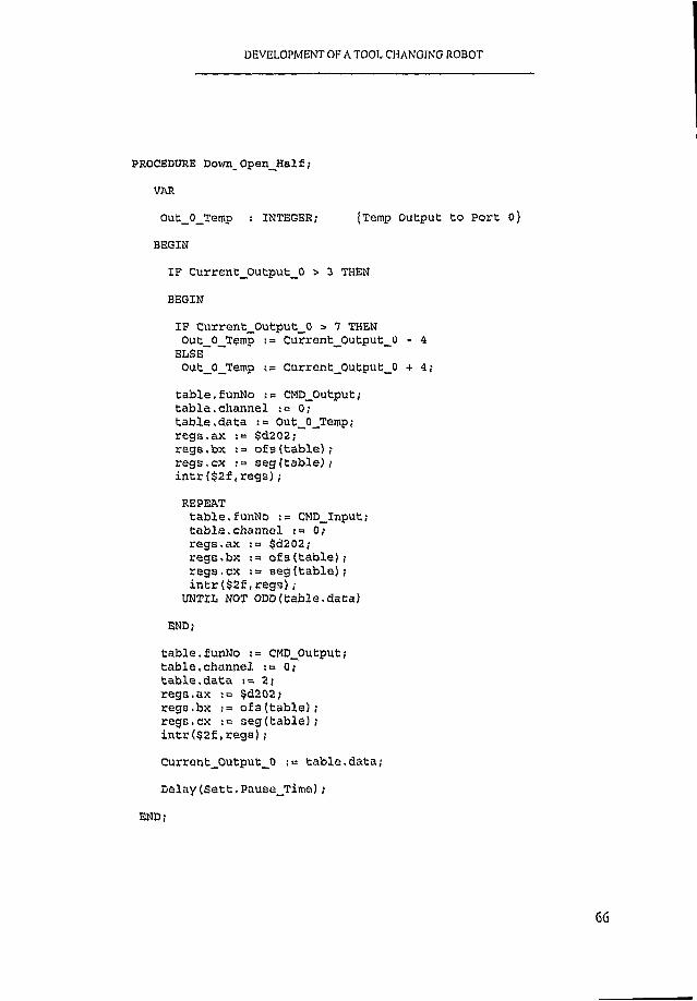
DEVELOPMENT OF A TOOL CHANGING ROBOT
PROCEDURE D o w n . O p e n J K a l f ;
VAR
G u t _ 0 _ T e m p ; INTEGER; {Temp O u t p u t t o P o r t 0}
BEGIN
I F C u r r e n t _ 0 u t p u t _ 0 > 3 THEN
BEGIN
I F G u r r e n t _ 0 u t p u t _ _ 0 > 7 THEN Qu t _ 0 _ T e m p := C u r r e n t _ O u t p u t _ 0 - 4
ELSE ~O u t _ 0 _ T e m p t = C u r r e n t _ Q u t p u t _ 0 + 4 ;
t a b l e . f u n N o := C M D _ O u tp u t ; t a b l e . c h a n n e l : = 0 ; t a b l e . d a t a := O u t _ 0 _ T e m p ; r e g s . a x : = $ 6 2 0 2 ; r e g s . b x := o f s ( t a b l e ) ; r e g s . c x := s e g ( t a b l e ) ; i n t r ( $ 2 f , r e g s ) ;
REPEATt a b l e . f u n N o := C M D _ I n p u t ; t a b l e , c h a n n e l ; = 0; r e g s . a x ;= $ d 2 0 2 ,- r e g s . b x -.= o f s ( t a b l e ) ; r e g s . c x ; = s e g ( t a b l e ) ,* i n t r ( $ 2 f , r e g s ) ;
UNTIL NOT O D D ( t a b l e . d a t a )
END;
t a b l e , f u n N o := C M D _ O u t p u t ; t a b l e . c h a n n e l := 0 ; t a b l e . d a t a : = 2 ; r e g s . a x i = $ d 2 0 2 ; r e g s . b x := o f s ( t a b l e ) ; r e g s . c x i= s e g ( t a b l e ) ; i n t r ( $ 2 f , r e g s ) ;
C u r r e n t _ o u t p u t _ _ o .•= t a b l e . d a t a ;
D e l a y ( S e t t , P a u s e j r i m e ) ;
END;

DEVELOPMENT OF \ TOOL CHANGING ROBOT
PROCEDURE n p _ O p e n _ H a 1 £ ;
VAR
O u t _ 0 _ T e m p : INTEGER; {Temp O u t p u t t o P o r t 0}
BEGIN
I F C u r r e n t _ 0 u t p u t _ 0 > 3 THEN
BEGIN
I F C u r r e n t _ 0 u t p u t _ 0 > 7 THEN O u t _ 0 _ T emp := C u r r e n t _ 0 u t p u t _ 0 - 4
ELSE "*O u t _ 0 _ T e m p := C u r r e n t _ 0 u t p u t _ 0 + 4 ;
t a b l e . f u n N o := CM D_Outpufc ; t a b l e . c h a n n e l : = 0 ; t a b l e . d a t a := O u t _ 0 _ T e m p ; r e g s . a x := $ d 2 0 2 ; r e g s . b x := o f s ( t a b l e ) ; r e g s . c x := s e g ( t a b l e ) ; i n t r ( $ 2 f , r e g s ) ;
REPEATt a b l e . f u n N o : « C M D _ l n p u t ; t a b l e . c h a n n e l ;= 0 ; r e g s . a x := $ d 2 0 2 ; r e g s . b x := o f s ( t a b l e ) ; r e g s . c x := s e g ( t a b l e ) ; i n t r ( $ 2 f , r e g s ) ;
UNTIL NOT O D D ( t a b l e . d a t a )END;
t a b l e . f u n N o := C M D _ O u t p u t ; t a b l e . c h a n n e l := 0 ; t a b l e . d a t a := 3 ; r e g s . a x : = $ d 2 0 2 ; r e g s . b x := o f s ( t a b l e ) ; r e g s . c x s= s e g ( t a b l e ) ; i n t r ( $ 2 f , r e g s ) ;
C u r r e n t _ 0 u t p u t _ 0 ;= t a b l e . d a t a ;
D e l a y ( S e t t . P a u s e _ T i m e ) ;
END;
67

DEVELOPMENT OF A TOOL CHANGING ROBOT
PROCEDURE R o t a t e ( V A R C u r r e n t _ P o s , N e w _ P o s : IN T E G E R );
{ROTATES t h e a r m t o t h e n e w p o s i t i o n , f r o m c u r r e n t _ p o s t o n em _ p o s )
VAR
S t e p s _ t o _ r o t a t e INTEGER;D i r e c t i o n : INTEGER;
BEGIN
{ IN IT IA L CALCS AND D IRN CHECKS}
S t e p s _ t o _ R o t a t e := N e w _ P o s - C u r r e n t _ p o s ;
I F S t e p s _ t o _ R o t a t e > 0 THEN D i r e c t i o n := _CW1
ELSE D i r e c t i o n := _CCW1;
S t e p s _ t o _ R o t a t e := A B S ( S t e p s _ t o _ R o t a t e ) ;
{CLEAR ANY PREVIOUS CURVES}
t a b l e . f u n N o := C M D _ C l e a r ; t a b l e . c h a n n e l := _ C H 1 ;
r e g s . a x := $ d 2 0 2 ; r e g s . b x := o f s ( t a b l e ) ; r e g s . c x s = s e g ( t a b l e ) ;
i n t r ( $ 2 f , r e g s ) ;
68

DBVEl OPMENT OF A TOOL CHANGING ROBOT
{CHECK NEW POS <> OLD POS}
I F S t e p s _ T o _ R o t a t e «> v THEN BEGIN
(ACCELERATE)
t a b l e . f u n N o := C M D _ S e t S t e p ;t a b l e . c h a n n e l •= _CH1 o r D i r e c t i o n ;t a b l e . v i := 0 ;t a b l e . v f := S e t t . M a x _ S p e e d ;t a b l e . s t e p : = S e t t . A c c _ S t e p s ;
r e g s , a x ;= $ d 2 0 2 ; r e g s . b x : = o f s ( t a b l e ) ; r e g s . c x ;= s e g ( t a b l e ) ; i n t r ( $ 2 f , r e g s ) ;
( c o n s t VELOVITY p h a s e }
t a b l e . f u n N o := C M D _ S e t S t e p ; c a b l e . c h a n n e l := _CH1 o r D i r e c t i o n ; t a b l e , v i := S e t t . M a x _ S p e e d ; t a b l e . v f := S e t t , M a x _ S p e e d ;t a b l e . s t e p := S t e p s _ t o _ R o t a t e - 2 * S e t t , A c c _ S t e p s ;
r e g s , a x := $ d 2 0 2 ; r e g s . b x := o f s ( t a b l e ) ; r e g s . c x s= s e g ( t a b l e ) ;
i n t r ( $ 2 f , r e g s ) ;
(DECELERATION PHASE}
t a b l e . f u n N o := C M D _ S e t S t e p ;t a b l e . c h a n n e l := _CH1 o r D i r e c t i o n ;
t a b l e . v i •.= S e t t , M a x _ S p e e d ;
t a b l e . v f i= Oj
t a b l e . s t e p := S e t t . A c q _ S t e p s ;
r e g s . a x := $ d 2 0 2 ;
r e g s . b x o f s ( t a b l e ) ;
r e g s . c x :«= s e g ( t a b l e ) ;
i n t r ( $ 2 f , r e g s ) ;

DEVELOPMENT OF A TOOL CHANGING ROBOT
{TRANSFER DATA TO DRIVER CARD}
t a b l e . f u n N o := C M D _ T r a n s f e r ;
t a b l e . c h a n n e l := _ C H 1 ;
r e g s . a x := $ d 2 0 2 ;
r e g s . b x := o f s ( t a b l e ) ;
r e g s . c x := s e g ( t a b l e ) ;
i n t r ( $ 2 f , r e g s ) ;
{RUN CURVES}
t a b l e . f u n N o := CMD_Run;
t a b l e . c h a n n e l := _ C H 1 ;
r e g s . a x := $ d 2 0 2 ;
r e g s . b x := o f s ( t a b l e ) ;
r e g s . c x := s o g ( t a b l e ) ;
i n t r ( $ 2 f , r e g s ) ;
END;
C u r r e n t _ P o s := N e w _ P o s ;
D e l a y ( S t e p s _ t o _ _ R o t a t e + S e t t . P a u 3 e _ T i m e ) ;
END;
PROCEDURE T o o l _ N u m b e r ;
{GETS INPUT OF TOOL NUMBER FROM EITHER THE P C L -8 3 S }{INPUT PORT ( 3 -B IT ) OR KEYBOARD)
VAR
T e m p i i S TR IN G ; {TEMPORARY STORAGE FOR TOOL NUMBER)
70

DEVELOP! Ik. T OF A TOOL CHANGING ROBOT
N u m l , Num2, C o u n t , T e m p _ x : INTEGER;e r r : INTEGER; (FOR V A L ID IT Y CHECK -KEYBOARD INPUT]
BEGIN
C l r S c r ;W RITSLN( ' T o o l C h a n g e R o b o t f o r CNC M i l l i n g
M a c h i n e 1) ;W r i t e l n ; W r i c e l n ; W r i t e l n ; v m iT E L N C P r e s s " x " t o E x i t ' ) ;W r i t e l n ;WRITELN( 1 P r e s s " wo M o d i f y C o n t r o l S e t t i n g s ' ) ;W r i t e l n ; W r i t e l n ;
E x i t _ V a r := ' a ' ;
CASE S e t t . I n p u t _ M e t h o d OP
1 : BEGIN { IF INPUT_METHOD = 1 , INPUT FROM M ILL}
W RITELN( 1 A u t o m a t i c M o d e ' ) ;
W r i t e l n ;
C o u n t : = 0 ;
REPEAT {LOOP TO READ DATA FROM PORT 0}
t a b l e . f u n N o := C M D _ I n p u t ; {UNTIL A VALID NUMBER I S INPUT}
t a b l e . c h a n n e l := 0 ;
r e g s . a x := $ d 2 0 2 , - r e g s . b x :=• o f s ( t a b l e ) ; r e g s . c x := s e g ( t a b l e ) ; i n t r ( $ 2 f , r e g s ) ;
I P K e y p r e s s e d THEN {CHECKS XF 'X ' X S PRESSED TO E X IT ]E x i t _ V a r := R e a d K e y ;
I ? T a b l e . D a t a = T c m p _ x t h e n
C o u n t := C o u n t + 1
ELSE C o u n t := 0 ;
T em p_X := T a b l e . D a t a ;
UNTIL ( ( t a b l e . d a t a < 2 2 3 ) AND <C o u n t = 1 0 ) )
OR ( U P C A S E ( E x i t _ V a r ) = ' X ' ) OR ( U P C A S E ( E x i t _ V a r ) = " = ' ) ;
71

DEVELOPMENT OF A TOOL CHANGING ROBOT
I F U P C A S E ( B x i t _ V a r ) <> ' X ' THEN
BEGIN
N u m l := t a b l e . d a t a SHR 2 ; {CALCULATING VALUE OF} { B IT S 3 - 5 }
Num2 := n u m l SHR 3 ; {FROM 8 B I T INPUT]N e w _ T o o l := (N um l - (Num2 SHL 3 ) ) ;
W r i t e l n ;
W R IT E L N ( 'N e w T o o l N o : ' , N e w _ T o o l , ' R e q u e s t e d ' )
END
END;
2 : BEGIN {lNPUT_METHOD--~. 2 , INPUT FROM KEYBOARD}
W r i t e l n ( ' E n t e r t h e New T o o l N u m b e r (1 - 6 ) ' ) ;
REPEAT {LOOP WAITING FOR VALID ENTRY}R e a d l n ( T e m p i ) ;
I F ( T e m p i = ' X ' ) OR ( T e m p i = ' X ' ) {ENTERING AN 'X ' WILLE X IT }
THEN E x i t _ V a r := 'X 'ELSE V A L ( T e m p i , N e w _ T o o l , e r r ) ;
I F ( e r r <> 0) OR ( N e w _ T o o l < 1) {V A L ID IT Y CHFCKING}OR (New_TO Ol > 6 ) THEN
W r i t e l n ( ' E r r o r - e n t e r a N u m b e r b e t w e e n 0 a r . d 6 ' ) ;
UNTIL ( ( e r r = 0) AND ( N e w j r o o l > 0) AND ( N e w _ T o o l < 7 ) )OR ( U P C A S E ( E x i t _ V a r ) = " " 'X ' ) OR ( U P C A S E ( E x i t _ V a r ) = ' S ' ) ;
END;
END { c a s e }
END;
72

DEVELOPMENT OF A TOOL CHANGING ROBOT
PROCEDURE C l a m p _ U n c l a m p ;
{SENDS OUTPUT TO RELAY 4 FOR 1 SECOND TO AC TIVATE M ILL CLAMP}
BEGIN
t a b l e . f u n N o := C M D _ O u t p u t ; t a b l e . c h a n n e l := 0 ;
t a b l e . d a t a := ( C u r r e n t _ 0 u t p u t _ 0 + 1 6 ) ;
r e g s . a x := $ d 2 0 2 ;
r e g s . b x := o f s ( t a b l e ) ;
r e g s . c x := s e g ( t a b l e ) ;
i n t r ( $ 2 f , r e g s ) ;
D e l a y ( 1 0 0 0 ) ;
t a b l e . f u n N o : = C M D _ O u t p u t ;t a b l e . c h a n n e l := 0 ;t a b l e . d a t a s= C u r r e n t _ G u t p u t _ 0 ;
r e g s . a x ;= $ d 2 0 2 ; r e g s . b x := o f s ( t a b l e ) ; r e g s . c x := s e g ( t a b l e ) ;
i n t r ( $ 2 f , r e g s ) ;
D e l a y ( 5 0 0 ) ;
END;
PROCEDURE W a i t i n g ;
{SENDS OUTPUT TO RELAY FOR 2 4 V SIGNAL TO M ILL TO IN D IC ATE}
{ROBOT ID LE AND JOB COMPLETE}
73

DEVELOPMENT OF A TOOL CHANGING ROBOT
BEGIN
t a b l e . f u n N o := C M D J D u tp u t ; t a b l e . c h a n n e l := 0 ;t a b l e . d a t a := ( C u r r e n t _ 0 u t p u t _ 0 + 3 2 ) ;
r e g s . a x -. = $ d 2 0 2 ; r e g s . b x := o f s ( t a b l e ) r e g s . c x := s e g ( t a b l e ) ;
i n t r ( $ 2 f , r e g s ) ;
D e l a y ( 1 0 0 0 ) ;
END;
PROCEDURE T e s t ;
{PROCBDUTE TO TE ST SYSTEM FUNCTIONS I N MANUAL MODE, IN D IVID U ALLY)
VAR
V a l u e j INTEGER; fTEMPORARY STORAGE OF VARIABLES}
BEGIN
C u r r e n t _ _ P o s s= 0 ;
REPEATc l r s c r ;W RITELN( 1 E n t e r t h e N u m b e r R e p r e s e n t i n g t h e F u n c t i o n 1) ; W r i t e l n ; W r i t e l n ;
W RITELN( ' 1 . D o \ m _ I n _ C l o s e ' ) ;
W RITELN( ' 2 . U p _ i n _ C l o s e ' ) ;
WRITELN( ' 3 . U p _ O u t _ C l . ) ;
W RITELN( 14 . D o w n _ O u t _ C l o s e ' ) ;
W RITELN( 15 . D o w n _ O u t _ O p e n ' ) ;
W R ITELN( ' 6 . U p _ O u t _ O p e n ' ) ;
74

DEVELOPMENT OF A TOOL CHANGING ROBOT
WRITELN( ' 7 . R o t a t e t o B a s e ' ) ;
WRITELN( ' 8 . R o t a t e T o o l l 1) ;
WRITELN( ' 9 . R o t a t e T o o l 3 ' ) ;
WRITELN( ' 1 0 . R o t a t e T o o l 6 ' ) ;
WRITELN( ' 1 1 . R o t a t e M i l l ' ) ;
WRITELN( ' 1 2 . D o w n _ C l o s e _ H a l f ' ) ;
WRITELN( ' 1 3 . D o w n _ O p e n _ H a l f ' ) ;
WRITELN( ' 1 4 . E X I T ' ) ;
R E A D L N ( V a lu e ) ;
CASE V a l u e OF {USES STATEMENT L I S T FUNCTIONS)
1 ; D o w n _ C l o s e _ I n ;
2 : U p _ C l o s e _ I n ;
3 s U p _ C l o s e _ O u t ;
4 i D o w n _ C l o s e _ O u t ;
5 : D o w n _ O p e n _ O u t ;
6 : U p _ O p e n _ o u t ;
7 i R o t a t e ( C u r r e n t _ P o s , B a s e _ P o s ) ;
8 : R o t a t e ( C u r r e n t _ P o s , T o o l _ P o s [ 1 ] ) ;
9 : R o t a t e ( C u r r e n t J ? o s , T o o l_ _ P o s [ 3 ] ) ;
1 0 : R o t a t e ( C u r r e n t _ P o s , T o o l _ P o s [ 6 ] ) ;
1 1 : R o t a t e ( C u r r e n t _ P o s , M i l l _ P o s ) ;
1 2 : D o w n _ C l o Q e _ H a l £ ;
1 3 : D o v m _ O p e n _ H a l £ ;
1 4 : W r i t e l n ( 'G o o d B u y ' ) ;
ELSE W r i t e l n ( ' E r r o r - T r y A g a i n ' )END { C a s e }
UNTIL V a l u e « 14 END;
75

DEVELOPMENT OF A TOOL CM, NGING ROBOT
PROCEDURE Check__A rm _D ovm ;
{PROCEDURE TO CHECK ARM MOVES DOWN AFTER TOOL I S RELEASED}
{FROM M ILL , INCASE I T GETS STUCK. I N SUCH CASE, THERE I S }{AN AUDABLE BEEP}
VAR
C h e c k l : INTEGER; {Temp s t o r a g e f o r c h e c k i n g s e n s o r v a l u e }T e s t l ! BOOLEAN;
BEGIN
REPEAT T e s t l sb F a l s e ;D e l a y ( 1 0 0 0 ) ;
t a b l e . f u n N o := C M D _ I n p u t ; t a b l e . C h a n n e l := 0 ; r e g s , a x i = $ d 2 0 2 ; r e g s . b x ; = o f s ( t a b l e ) ; r e g s . c x : = s e g ( t a b l e ) ; i n t r ( $ 2 f , r e g s ) ;
C h e c k l := t a b l e . d a t a s h r 1 ;
I F O D D ( C h e c k l ) THEN BEGIN
I F NOT T e s t l THEN BEGIN
WRITELN( ' T h e r e i s a p r o b l e m w i t h t h e A rm n o t m o v i n g d o w n 1) ; T e s t l : n T r u e
END;
SOUND( 7 0 0 ) i D e l a y ( 5 0 0 ) ;N o S o u n d ;D e l a y ( 1 0 0 0 ) ;
END;
U N T IL NOT O D D ( C h e c k l ) ;
I F T e s t l THEN W RITELN( 1 P r o b l e m i s r e s o l v e d ' ) ;
END;
76

DEVELOPMENT OF A TOOL CHANGING ROBOT
PROCEDURE G e b _ C u r r e n b _ T o o l ;
{MOVEMENT OF ARM VO FETCH TOOL I N USE}
BEGIN D o w n _ C l o s e _ I n ;R o t a t e ( C u r r e n t _ P o s , M i l l _ P o s ) ;U p _ O p e n _ I n ;
CASE S e t t . M i l l . _ E x t OF
1 : BEGINU p _ 0 p e n _ 0 u t ;U p _ C l o s e _ O u t ;C l a m p _ U n c l a m p ; { S e n d O u t p u t t o M i l l t o R e l e a s e } D o w n _ C l o s e _ O u t ;I F S e t t . V e r t _ S e n s o r = 1Y 1 THEN
C h e c k A rm Down END;
2 ; BEGINU p _ O p e n _ H a l f ;U p _ C l o s e _ H a l f ;C l a m p _ U n c l a m p ;D o w n _ C l o s e _ H a l £ ;I F S e t t . V e r t _ S e n s o r = ' Y ' THEN
C h e c k _ A rm _ D o w nEND
END;
D o w n _ C lo a e _ _ In ;R o t a t e ( C u r r e n t _ P o a , T o o l _ P o s [ C u r r e n t _ T o o l ] ) ; D o w n _ C l o s e _ O u t ;D o w n _ O p e n _ O u t ;D o w n _ O p e n _ I n ;D o w n _ C l o s e _ I n ;
END;
P r o c e d u r e P u t _ N e w _ T o o l ;
{MOVEMENT OF ARM TO PVT NEW TOOL ON M ILL)
BEGIN
R o t a t e ( C u r r e n t _ P o s , T o o l _ P o s [ N e w _ T o o l ] ) ;
D o w n _ O p e n _ I n ;
D o w n _ O p e n _ O u t ;
D o w n _ C l o a e _ O u t ;

DEVELOPMENT OF A TOOL CHANGING ROBOT
D o w n _ C l o s e _ I n ;
R o t a t e ( C u r r e n t _ P o s , M i l l _ P o s ) ;
CASE S e t t . M i l l _ E x t OF
1 •. BEGIN
D o w n _ C l o s e _ O u t ;
U p _ _ C l o s e _ O u t ;
C l a m p _ U n c l a m p ; f O u t p u t t o M i l l t o g r i p t o o l }
U p _ Q p e n —O u t i
END;
2 i BEGIND o w n _ C l o s e _ H a l £ ;U p _ _ C l o s e _ H a l £ ;C l a m p _ U n c l a m p ; f O u t p u t t o M i l l t o g r i p t o o l JU p _ O p e n _ H a l £ ;
END
END;
U p _ O p e n _ I n ;
D o w n _ C l o s e _ I n ;
R o t a t e ( C u r r e n t _ P o s , B a s e _ P o s ) ;
C u i ' r e n t _ T o o l : = N e w _ T o o l
END;
78

DEVELOPMENT OF A TOOL CHANGING ROBOT
PROCEDURE W e l c o m e ;
{i n t r o d u c t io n s c r e e n )
VAR
C h , C h i : CHAR;T o o l : INTEGER;
T e s t l , T e s t 2 : BOOLEAN;
BEGIN
C l r s c r ;
W R ITELN( ' T o o l C h a n g e R o b o t f o r CMC M i l l i n gM a c h i n e ' ) ;
W r i t e l n ; W r i t e l n ; W r i t e l n ;W R ITELN( ' P l e a s e P o s i t i o n t h e R o b o t A rm a t 0 d e g r e e s a n d p r e s s
[ENTER] 1 ) ;READLN;W r i t e l n ; W r i t e l n ;
W R ITELN( 1 W o u l d y o u l i k e t o m o d i f y t h e R o b o t V a r i a b l e S e t t i n g s (Y / N) ? ' ) ;
REPEAT T e s t l : = T r u e ;C h i := R e a d k e y ;
CASE U p c a s e ( C h l ) OF
' Y ' : BEGINC h a n g e _ S e t t i n g s ;T e s t l := F a l s e ;
END;
' N ' ! T e s t l ;= F a l s e ;
END; { o f CASE)
UNTIL NOT T e s t l ;
W RITELN( 1 W o u l d y o u l i k e t o r u n t h e TEST p r o g r a m ( Y / N ) 1) ;
79

DEVELOPMENT OF A TOOL CHANGING ROBOT
REPEATT e s t l := T r u e ;
C h i ;= R e a d k e y ;
CASE U p c a s e ( C h l ) OF
1Y ' : BEGIN
T e s t ;
T e s t l •= F a l s e ;
END;
' N ' : T e s t l := F a l s e
END;
U N T IL NOT T e s t l ;
C u r r e n t _ P o s : = 0 ;W r i t e l n ; W r i t e l n ;W R ITELN( 1 I s t h e r e c u r r e n t l y a T o o l i n U s e ( Y / N ) ? 1) ;
REPEAT T e s t l : = TRUE;C h := R e a d k e y ;
CASE U p c a s e ( C h ) OF
' Y ' i BEGINW r i t e ( 1 P l e a s e E n t e r T o o l N u m b e r ( 1 - 6 ) ' ) ;REPEAT
R e a d l n ( T o o l ) ;I F ( T o o l < 1 ) OR ( T o o l > 6 ) THEN
BEGIN W r i t e l n ;W RITELN( ' E r r o r - P l e a s e r e - e n t e r T o o l N u m b e r ' ) ; W r i t e l n ;
END;U N T IL ( T o o l > 0 V AND ( T o o l < 7 ) ;C u r r e n t _ T o o l ;= T o o l
END;
' N 1 ! C u r r e n t _ T o o l : = 0 ;
ELSE T e s t l := FALSE;
END; {CASE}UN TIL T e s t l ;
END;
80

DEVELOPMENT OF A TOOL CHANGING ROBOT
{M A IN PROGRAM BLOCK)
BEGIN
E x e c ( 1c ■\ r o b o t \ p r o g 8 3 8 \ p c l - 8 3 8 . e x e 1 , 1 1 ) ; {LOAD SOFTWARE DRIVER P C L -8 3 8 }
C h e c k l ; {CHECK SOFTWARE INSTALLED}
B a a e _ A c ' : i v e ; {SE TS THE CARDS BASE ADDRESS} {AND AC TIVATES CHANNEL 1}
D o w n _ C l o s e _ I n ;
G e t _ S e t t i n g s ;
C u r r e n t _ P o s := 0 ;
W e l c o m e ;
S e t _ P o s n _ S t e p a ;
H a l £ _ O u t _ T e s t := F a l s e ;
{ENSURES a r m i n h o m e p o s i t i o n }
(LOADS VARIABLE SE TTIN G S}
(INTRODUCTION SCREEN}
(CALCULATES RADIAL P O SITIO N S IN } {STEP COORDINATES}
REPEAT
(LOOP WHICH GETS TOOL NUMBER AND EXECUTES TOOL CHANGE}
W a i t i n g ; (OUTPUT TO IND ICATE NOT BUSY TO M ILL}
T o o l _ N u m b e r ; (CONTINUOUS LOOP UNTIL 3 - B I T INPUT}(FOR TOOL NO}
I F ( N e w _ T o o l <> C u r r e n t _ T o o l ) THEN (CHECK NEW TOOL I S NOT}(CURRENT ONE}
BEGIN
I F ( C u r r e n t J C o o l <> 0) AND (UPCASE ( E x i t J Z a r ) o ' X ' ) THEN (CHECKS A TOOL I S I N USE}

DEVELOPMENT OF A TOOL CHANGING ROBOT
BEGIN
W RITELN( ' G e t t i n g t o o l ' ) ;
G e t _ C u r r e n t _ T o o l ; {PROCEDURE TO GET TOOL FROM M ILL)
END;
W RITELN( 1 P u t t i n g T o o l 1) ;
P u t _ N e w _ T o o l ; {PROCEDURE TO PU1' NEW TOOL ON M ILL}
END;
I F U P C A S E ( E x i t _ V a r ) = ' S ' THEN
BEGIN
C h i . , n g e _ _ S e t t i n g s ;
S e t _ P o o n _ S t e p a ; ;
END;
UNTIL U P C A S E ( E x i t _ V a r ) = ' X 1 ; {E X IT S LOOP I F A 'X ' I S ENTERED}
R e g s . a x := $ d 2 0 1 ; {U N -IN STA LLS P C L -8 3 8 ){SOFTWARE DRIVER]
I n t r ( $ 2 E , r e g s )
END*
82

DEVELOPMENT OF A TOOL CHANGING ROBOT
A P P E N D IX B
GENERAL ASSEMBLY DRAWINGS

L I N E A R B E A R I N G S
H O R I Z O N T A L G U I D E S H O R I Z O N T A L S U P P O R T F RAME —
G R I P P E R A S S E M B L Y
C Y L I N D E R F E S T O D S N N - 1 6 - 2 0 0 P P V A
L I N E A R B E A R I N G S
C L Y L I N O E RF E S T OD S N - 2 5 - 1 6 0 - P
P R O T R A C T O R - F E ' T O P R E S S U R E
R E G U L A T O Rc rV E R T I C A L G U I D E S
V E R T I C A L S U P P O R T —F R AME
V E R T I C A L S H A F T
MA I N S U P P O R T FRAMES T E P P E R MOTOR & G EAR BOX
E L E V A T I O N ON R O B O T I C ARM T O O L S E L E C T O R
T IT L E :
DRAW N
S C A L Ee : \ d g n \ r o D o t . d g n Mar. 25, 1999 1 0 :2 4 :o ?

G R I P P E R ASSEIvi :
/ I
C Y L I N D E R F E S T O D S N N - 1 6 - 2 0 0 P P V A
P R O T R A C T O R- F E S T O P R E S S U R E R E G U L A T O R
I I I I
i—r
x— TOOL L O C A T E R
TOOL H O L D E R
, — TOOL S U P P O R T F RAME
MA I N S U P P O R T FRAME
A T I O N ON R O B O T I C ARM T O O L S E L E C T O R
TITLE: R O B O T I C ARM T O O L S E L E C T O R
P R E V I O U S U N I T :DRAW N
S C A L E : 5
DRG. NO. REV

P L A N
1 5 FINGER P IN
14 WASHER, LOCK
13 WASHER, FLAT
1 2 SCREW CAP SOCKET b
1 1 SCREW CAP SOCKET h
10 CYLINDER, PNUEMA"
9 SWIVEL BUSH
8 SWIVEL PIN
7 PLATE GUIDE I
6 GRIPPER BRACKET:
5 PUSHER BEAM P H : '
4 STRUT
3 PUSHER BEAM
2 GRIPPER FINGER1 GRIPPER CHASSIS
IT E M N . o NAME
T IT L E :
ROBIG R I P P E
DRAW N
S C A L E 1 : 1 . 5
. Q . n
tzr
E L E V A T I O N ON R O B O T G R I P P E R
e : \ d g n \ r D d o t . dgn Mar. 24, 1999 0 7 :2 9 :0 2

P L A N
c i
"CJ
E L E V A T I O N ON R O B O T G R I P P E R
15 F I N G E R P I N 2 0 5 X 15 LG. BRASS1 4 W A S H E R , L O C K 4
1 3 W A S H E R , F L A T 4
1 2 S C R E W C A P S O C K E T H D . 4 M 4 X 1 5 L G .1 1 S C R E W C A P S O C K E T H D . 4 W3 X 15 LG.10 C Y L I N D E R , P N U E M A T I C 1 DGS- 16- 40- P FESTO
9 S W I V E L B U S H 4
8 S W I V E L P I N 2
7 P L A T E G U I D E 2
6 G R I P P E R B R A C K E T 1
5 P U S H E R BEAM P I N 2 0 5 X 15 LG. BRASS4 S T R U T 2
3 P U S H E R B E A M 1
2 G R I P P E R F I N G E R 2
i G R I P P E R C H A S S I S 11 1 L M N . 0 NA ME O U A N T I ' I Y D E S C R I P T I O N
TITLE:
R O B O T I C ARIvl G R I P P E R A S S E M B L Y
DRAWN
S C A L E 1 : 1 . 5DRG. NO. REV
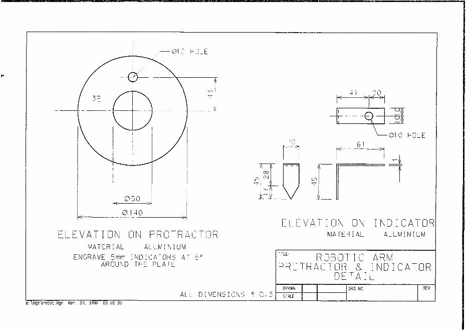
0 1 2 HOLE
0 5 0
E L E V A T I O N ON P R O T R A C T O RMATERIAL ALUMINIUM
E N G R A V E 5 m m I N D I C A T O R S AT 5 ° AROUND THE P L A T E
T T TooCM
IT LV
20
3
0 1 0 H OL E6 !
E L E V A T I O N ON I N D I C A T O RMATERIAL ALUMINIUM
ALL D I M E N S I O N S ± 0 . 5
R O B O T I C ARM P R O T R A C T O R & I N D I C A T O R
D E T A I LDRAW N
S C A L ED R G . NO. R E V
e : \ f l g n \ r a t i o t . d g n M a n . 2 4 , 1 9 9 3 OB: 2 0 : 3 0

e : \d g n \p o t io t .c lg n Mar. 23, 1999 17 :41 :53
/ / /
V // / ' •
¥
T OOL H O L D E RA L U M I N I U M
E L E V .
ALL D I M E N S I O N S I 0 . 2
T IT L E :
DRAW N
S C A L E
F.(

P L A N O N T O O L H O L D E RM A T E R I A L A L U M I N I U M
5 5 , 6 5 5 0
i—r
z— TOOL / L O C A T E R
o
“ T
E L E V . ON T O O L H O L D E R
ALL D I M E N S I O N S ± 0 . 2
TITLE'- R O B O T i C ARVIT O O L H O L D E R
DRAW N D R G . N O. R E V
SCALE 1 : 5

CHAM.
in
0 8 H O L E -D R I L L T A P M8
PLAI
LO
M8
0 8 + 0 . 0 0- 0 . 2
in
L O C A T I N G P I NM A T E R I A L M I L D S T E E L
S E C T I O N T H R O ' T O O L L O G A T E RM A T E R I A L M I L D S T E E L
T O L E R A N C E 0 . 5 UNOe: N d g n V o b o L d g n M ar, 2 < 1999 OB: -14: 35
TITLE- R O B O T I C A R M T O O L L O C A T E R D E T A I L
DRAW N D R G . N O. R E V
S C A L E 1 : !

oo
nmC D
min
i
o Jd
J
rI P L .
135 140< 5 - - - - - - - - - - - - - - - 5 > i
P L A N150
5PL .— ---
i i . i... i ~
" I ' 1 ' 1 ‘T 1 •
4 0 X 4 0 X 1 . 6 S O . T Y P . UNO
E L E V A T I O N M A I N S U P P O R T F R A M E
Oo
oxrcn
m
co
T IT L E :
R Q M A I N 3
T O L E R A N C E 0 . 5 UNO DRAW N
S C A L Ee : \ d g n \ r o t i o t . d g n Mar. 23, 1999 16 :03 :03

: 5 3 5
i i
w ,*» dd I
1 rI b
5 P L
. I /
ooN"
1\
o oT XTin
\i
OoTT
1i \ i
4 5 5 1 5 0--------- sh
AN
in
00
1. 6 S O . T Y P . UNO
U N S U P P O R T F R A M ET O L E R A N C E 0 . 5 UNO
TIT LE-R O B O T I 0 AR
M A I N S U P P O R T F R A M EDRAW N
SCALE 1 : 7 . 5DRG. NO. REV
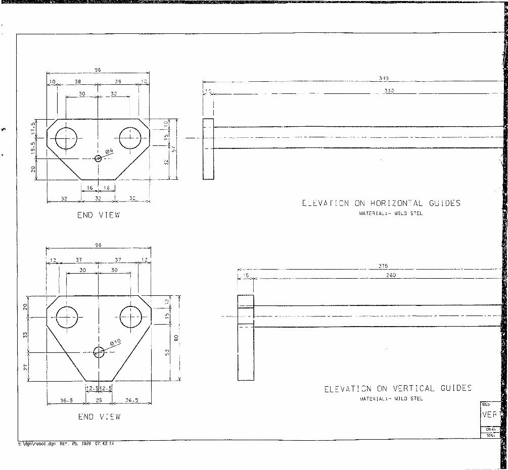
19
.
340
10 330
E N D V I E W
1 2 . 5 1 2 . 5
3 6 . 5
E N D V I E W
E L E V A T I O N O N H O R I Z O N T A L G U I D E SM A T E R I A L : - MILD STEL
275
2 6 0
E L E V A T I O N ON V E R T I C A L G U I D E SMA TE R I A L : - MILD STEL
TITLE:
V E R
o : \ d g n \ r o D o t . d g n Mar. 25, 1399 07:43: 14

3 10
10 3 3 0
E L E V A T I O N ON H O R I Z O N T A L G U I D E SM A T E R I A L : - MILD STEL
E L E V A T I O N ONMATERIAL:
V E R T I C A LMILD STEL
G U I D E S
R O B O T I C A R M V E R T I C A L & H O R I Z O N T A L
G U I D E SDRAWN
1 : 2DRG NO. T£T

102
3 7 . 5 3 7 . 535
0 3 630MILD STEEL INSERT
68
i ncxj
HOLES29 8
E N D V I E W E L E V A T I O N ON H O R I Z O N T A L G U I D E A R MMA TERIAL ALUMINIUM
e: Ndgnxrobot .ilgn Mar. 25. 1993 0 7 :0 5 :0 3

:e l i n s e r t
E L E V A T I O N O N H O R I Z O N T A L G L I D E A R MMATERIAL AL UM INI UM
i nI V
o "I V , ,
HOLES
30
2
j -j
E N D V I E W
R O B O T I C ARM H O R I Z O N T A L G U I D E A R M
1 :2

0 3 5M T T d X
STEELINSERT
E N D V I E W
e : \ d g n \ r o b o t . d g n Man. 25, 1939 06:47: 18
:72 145
50 20 167 15 30 16 99
CMGy IS)
/ I
jL
E L E V A T I O N ON V E R T I C A L G U I D E A R MMATERIAL :- AL UM I N I U M
T I T L E
D R A W !
S C ALE

272 145
50 20 167 3020
\ 012
5625. 56 .25
E L E V A T I O N ON V E R T I C A L G U I D E A R MMA TE R I A L A L U M I N I U M
E N D V I E W
R O B O T I C A R M V E R T I C A L G U I D E ARM
1 :2

DEVELOPMENT OF A TOOL CHANGING ROBOT
A P P E N D I X C
QUOTATION FOR CNC MILL MODIFICATIONS

;„s n * uC 3.3,
TEL: (Oil) 845-3278/9FAX: (Oil) 421-337320/10/1998REF NO: DBM/10/765ATTENTION: MR. GRAIG REID
RETROFU TiNG OF MACHINE .V7;SALES AND SERVICE OF CNC WC -I'NzS
Dun 5 war: !5C6
iuuT.' Afras
RE: DYNAPATH DELTA 20M CONTROL
Dear Sir
Herewith our quotation to change the software on the 1 y-nx Delua 20M control to accommodate a robot Tool changer as ’..,'11 as to supply the outputs and inputs required.Software changes (P.L.C) 16HRS S' R220-00 R 3 51Travel (1 x to Wits and Back) 1KR 0 R220-00 R 2
90KM S'" Rl-70 R If:SPARESPlugs and cables R 11= -to
R 4 043-00•14% VAT R 556-02TOTAL R 4 609-02
C.N.C TO ROBOT 24V D.CPinl « Binary Bit 1 Pin2 Binary Bit 2 Pin3 Binery Bit 4 Pin4 - Toolchangi: request
ROBOT TO C.N.C 24V D.CPin5 = Tool change, done Pin6 = Tool unciamp Pin? «=* OV
5cit' Ui-mbor D 3 Mjdi

r
As o’jr work allocation schedule is currently full till our annual Shutdown in December, I cannot commit myself co a ‘i'-ecific data, I will however try and make a plan to do the chages you requested before then but will advise you in thi regard.
T h a n k i n g y o u
D .B . Maas for Unimatin cc
■ a -E NO.
IMATIOMfisg N: C< 35 CeajEU'3

Author Read, David Craig. Name of thesis Development of a tool changing robot for a computer numerically controlled milling machine. 1999 PUBLISHER: University of the Witwatersrand, Johannesburg ©2013
LEGAL NOTICES:
Copyright Notice: All materials on the Un i ve r s i t y o f the W i twa te r s rand , Johannesburg L ib ra r y website are protected by South African copyright law and may not be distributed, transmitted, displayed, or otherwise published in any format, without the prior written permission of the copyright owner.
Disclaimer and Terms of Use: Provided that you maintain all copyright and other notices contained therein, you may download material (one machine readable copy and one print copy per page) for your personal and/or educational non-commercial use only.
The University of the Witwatersrand, Johannesburg, is not responsible for any errors or omissions and excludes any and all liability for any errors in or omissions from the information on the Library website.


![Kawasaki Robot Solutions K-ROSET · PDF fileK-ROSET Offline programming tool. K-ROSET. Kawasaki Robot. Kawasaki Robot Solutions] Materials and specifications are subject to change](https://img.pdfslide.us/doc/110x75/5a9eb5b87f8b9a8e178bb8fa/kawasaki-robot-solutions-k-roset-offline-programming-tool-k-roset-kawasaki-robot.jpg)