Embed Size (px)
Citation preview

C I R E D 20th International Conference on Electricity Distribution Prague, 8-11 June 2009
Paper 0533
DEVELOPMENT OF A TEST PROTOCOL FOR A 15 KV CLASS SOLID-STATE
CURRENT LIMITER
Ashok Sundaram Mahesh Gandhi Electric Power Research Inc., USA Silicon Power Corporation, USA [email protected] [email protected]
ABSTRACT The Solid-state Fault Current Limiter (SSFCL) is a new product for which no industry standard exists. This paper gives the overview of the effort to date to develop the test protocol for this new product. It involves the review of existing standards of several legacy electrical gears, survey of the high voltage test facilities, and review of Acceptance test criteria of several leading US-based Electrical Utilities. The resulting test protocol is a comprehensive document to apply to SSFCL to provide a reliable new product.
INTRODUCTION Growth in the generation of electrical energy, increased penetration of distributed resources and increased interconnection of the networks leads to higher fault currents. This growth in capacity requires replacing existing circuit breakers with units with higher fault current ratings, incurring a major cost and down time. Higher fault current causes more stress on the system reducing the life of critical components such as transformers. According to Pat Duggan of Con Edison, “Fault Current Limiting functionality is a critical enabler for ‘open access’ for new transmission and generation, and more cost effective infrastructure upgrades and replacements. In addition fault current limiters can mitigate recovery time of superconducting cables and give selected DGs an advanced option to serve peak loads after external faults.” [1] The SSFCL is a fault current limiter using solid-state technology providing active control of fault current limiting. In the event of fault SSFCL introduces the current limiting impedance till the fault is cleared.
SSFCL Concept:
Figure 1: SSFCL Concept Operation • Normally the continuous current flows through the fast
speed switch (Main SGTO) as shown in figure 1. • Once the fault is sensed by high-speed sensor and
declared by FPGA board, the current is commutated to Limiting Inductor (CLI).
• Introduction of CLI will limit the current to the level below the rating of the downstream breaker. The downstream breaker will trip and open the circuit within 30 cycles as shown in figure 2.
• Once the fault is cleared the SSFCL can perform Auto/Manual reset.
SSFCL Fault Current Limiting Effect
Figure 2: SSFCL limiting effect SSFCL Design Features The SSFCL incorporates the following features for ease of
CIRED2009 Session 1 Paper No 0533

C I R E D 20th International Conference on Electricity Distribution Prague, 8-11 June 2009
Paper 0533
operation, faster response, minimum system impact, improved reliability, better efficiency, and compact footprint. • Immediate recovery • Fail safe • No line current distortions • SGTO devices as shown in figure 3 • Lower losses • Reduced Overall size and weight • Modular design expandable to desired Voltage &
Current Ratings as shown in figure 4 & 5 • Robust construction for outdoor applications with
OFAF cooling, No cryogenics as shown in figure 6
Figure 3: R&D100 Award Winner SGTO Device
Figure 4 SSFCL Building Block – Internal detail
Figure 5 SSFCL Power Stack – Internal detail
Figure 6: 1200A SSFCL Outline - 12’ H 11’ W 12’D, 40000 lbs
CIRED2009 Session 1 Paper No 0533

C I R E D 20th International Conference on Electricity Distribution Prague, 8-11 June 2009
Paper 0533
SSFCL Projects SSFCL units are under development for the following projects. • 3 phase 15 kV, 1200A SSFCL funded by CEC to be
field tested at Southern California Edison on their “Avanti Circuit” in 2009.
• 3 phase 15 kV, 4000A SSFCL funded by DHS to be field tested at ConEdison, New York, on their “3G Circuit of the Future” in 2010.
• 1 phase 69 kV, 1000A SSFCL funded by DOE to be tested at an Independent Lab in 2009.
SSFCL FIELD TEST CIRCUITS
Con-Ed’s 3G Circuit of Future SSFCL in 3G Circuit of Future provides fault current limiting in the bus-tie circuit between two substations as shown in figure 7 & 8.
Figure 7 Con Edison 3G Application
Figure 8 Con Edison 3G Circuit
SCE’s “Avanti” circuit of the future SSFCL in SCE’s testing is to limit fault current in their innovative feeder circuit “Avanti” as shown in figure 9.
Figure 9 SCE Avanti Circuit
15KV SSFCL PERFORMANCE REQUIREMENTS Parameters [2]-[7] Req’t • Maximum Voltage, kV rms 15.5 • Max. Continuous Current, Ampere rms 1200/4000* • Power Frequency, Hz 60 • Available fault current, kA Sym. rms 23/11* • Let-thru Current, Sym. kA rms 9/5.5* • Let-thru Current Duration, cycles 30 • Dielectric Withstand
– Partial discharge pC @19.5kV 100 – Power Frequency 1 min, kV rms 50 – Impulse, Full-wave, kV peak 110 – Impulse, Chopped-wave, kV peak 142
• Max. Ambient Temp, Degree C 50/40* • Power Efficiency 99.75% • Line Harmonic Distortion None • Audible Noise 50dBA@20’
/58dBA@6’ *Application specific requirement
POWER TEST LAB CAPABILITIES The capability of various power labs in USA was assessed. The following is the summary of their capabilities to perform the desired tests on the SSFCL. • Partial discharge Test
– KEMA, Chalfont PA [8] – Capability: to 40 kV
• Power Frequency Voltage Withstand Test – KEMA, Chalfont PA – 150 kV
• BIL/ Impulse Full-wave Voltage Withstand Test – KEMA, Chalfont PA – 1000 kV
• Impulse, Chopped-wave Voltage Withstand Test – KEMA, Chalfont PA – 1000 kV
• Max. Continuous Current/ Temp. Rise Test – KEMA, Chalfont PA – 300 kA at 1300 V AC, 3 phase
CIRED2009 Session 1 Paper No 0533
C I R E D 20th International Conference on Electricity Distribution Prague, 8-11 June 2009
Paper 0533
• Full load Operation/ Power Efficiency/ Line
Harmonics Distortions Test – KEMA, Chalfont PA – 38 kV, 5000 A
• Fault current limiting Test – KEMA, Chalfont PA – 1000 MVA (16 kV) or 2250 MVA (16 kV)
generators available • Audible Noise test
– Noise Unlimited, Bordentown, NJ • EMI test
– Alion Science & Technology, R&B Lab, Conschohoken, PA
15KV SSFCL TEST PROTOCOL • Qualification Testing (subject of this paper)
– Design Testing – Utility Acceptance tests – Pre-connection tests – Field evaluation tests
• Production Testing
DESIGN TESTING The following tests have been formulated based on review of the industry standards for switchgears used in T&D system. • Dielectric Test [9], [12], [13], [14], [16]
– Insulation test by resistance measurement (Megger test)
– Insulation test by power factor measurement (Dobble test)
– Partial Discharge Test – Power frequency Voltage Withstand Test – Full-wave lightning impulse withstand voltage
tests – Chopped wave lightning impulse withstand
voltage tests – CLR resistance & impedance measurement
• Current Limiting Test • Efficiency (power loss) Test • Continuous Current Test/ Temperature Rise Test
[10], [11] • Audible Noise test • EMI
UTILITY ACCEPTANCE TESTS: The following tests have been derived from consultation with US based Utilities. • Insulation test by power factor measurement (Dobble
test) • Insulation test by resistance measurement (Megger
test) • Partial Discharge test • Full set of dielectric tests
PRECONNECTION TESTS AT UTILITY SUBSTATION: The following are the tests US based Utilities prefer to perform before applying power to the SSFCL in the field. • Visual Inspection • Tank Pressure test • Insulation/Dielectric tests
– Insulation test by power factor measurement (Dobble test)
– Insulation test by resistance measurement (Megger test)
FIELD EVALUATION TESTING In the field SSFCL will be evaluated for it’s performance under Steady-State and Transient (at fault) conditions
DETAILS OF TEST PROCEDURES : The following sections provide details of the procedures for key tests.
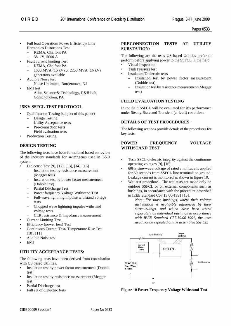
POWER FREQUENCY VOLTAGE WITHSTAND TEST • Tests SSCL dielectric integrity against the continuous
operating voltages [9], [16]. • 60Hz sine-wave voltage of rated amplitude is applied
for 60 seconds from SSFCL line terminals to ground. Leakage current is monitored as shown in figure 10.
• Wet test procedure - The wet tests are made only on outdoor SSFCL or on external components such as bushings, in accordance with the procedure described in IEEE Standard C57.19.00-1991 [15].
Note: For those bushings, where their voltage distribution is negligibly influenced by their surroundings, and which have been tested separately as individual bushings in accordance with IEEE Standard C57.19.00-1991, the tests need not be repeated on the assembled SSFCL.
Figure 10 Power Frequency Voltage Withstand Test
CIRED2009 Session 1 Paper No 0533

C I R E D 20th International Conference on Electricity Distribution Prague, 8-11 June 2009
Paper 0533
FULL-WAVE IMPULSE WITHSTAND VOLTAGE TEST • Tests to verify system’s ability to withstand rated full-
wave lightning impulse withstand voltages. • Both positive and negative, lightning impulse voltages
having a peak value equal or greater than the rated full-wave lightning impulse withstand voltage, as shown in figure 11 & 12, shall be applied between the terminals of the SSFCL and the ground / case as shown in figure 13.
• Waveform for lightning impulse tests per IEEE Standard 4-1978 [9]
Waveform for full-wave Impulse Test
Figure 11: Positive Impulse
Figure 12: Negative Impulse
Schematic for Full-wave Impulse Test
Figure 13: Full wave impulse test
CHOPPED-WAVE IMPULSE WITHSTAND VOLTAGE TEST
• To verify their ability to withstand their assigned rated chopped wave lightning impulse withstand voltage.
• The waveforms, figure 14 & 15, and the application of the chopped wave test voltage, and the type of rod gap and its location, shall be as described in IEEE Standard 4-1978 [9].
• The voltage shall be applied to the terminals of the SSFCL, without causing damage or producing a flashover, following the same procedure as for full-wave impulse test, as shown in figure 16.
Waveform for Chopped-wave Impulse Test
Figure 14: Linearly rising front chopped impulse
CIRED2009 Session 1 Paper No 0533

C I R E D 20th International Conference on Electricity Distribution Prague, 8-11 June 2009
Paper 0533
Figure 15: Lightning Impulse chopped on the tail
Schematic for Chopped-wave Impulse Test
Figure 16 Chopped wave impulse test
FULL LOAD/ EFFICIENCY/ HARMONIC DISTORTION TESTS • The purpose of the test is to evaluate the SSFCL
performance for full load operation, power losses and harmonic distortion at various current levels using the circuit as shown in figure 17 below.
• Test conditions • Input – At the lower end of operating
voltage range and higher end of input frequency.
• Output / load – At 25%/50%/75% and rated load current and 0.85 lagging power factor.
Figure 17 Efficiency Test
CONTINUOUS CURRENT / TEMPERATURE
RISE TESTS
Test conditions• Ambient – Room temperature. • Output – 3phase bolted short. • Input Voltage – Variable low voltage enough to
provide 25% and gradual rise to 50%-75% and finally to rated load current.
Temperature. Monitoring • Built in heatsink temperature. sensors • Cooling liquid temperature (Top, Mid, and lower level) • Tank (top, bottom, middle on both sides)
FAULT CURRENT LIMITING TEST • The purpose of the test is to evaluate the SSFCL
performance for fault current limiting operation. • The SSFCL is connected to the test set up as shown in
figure 18 below. • Test conditions
• Set source impedance for required available short circuit current.
• Set backup breaker for let-thru current for desired duration.
• Perform test starting with 25/50/75% of desired let-thru before hitting 100% of current.
Figure 18 Fault current Limiting Test
PRECONNECTION TEST
Visual Inspection Once received at site an external inspection of the SSFCL tank and fittings will be done which will include the following points: 1. Is there any indication of external damage? 2. Is the paint finish damaged? 3. Are the attached fittings loose or damaged? 4. Is there evidence of fluid leakage on or around the tank coolers? 5. Are any of the bushings broken or damaged?
CIRED2009 Session 1 Paper No 0533

C I R E D 20th International Conference on Electricity Distribution Prague, 8-11 June 2009
Paper 0533
6. Is there any visible damage to the parts or packaging which shipped separately from the SSFCL?
Tank Pressure The tank pressure may be positive or negative when received, depending on liquid temperature. In some cases, the vacuum pressure gauge may read zero, which could indicate a tank leak. In such cases, it is recommended to contact manufacturer before installation.
Dielectric tests Dielectric tests are the group of tests during which the SSFCL will be subjected to higher voltage levels and therefore higher voltage stresses than would normally be experienced in service. The purpose is to confirm that the design, manufacture and processing of the SSFCL and insulation structure and materials are adequate to provide many years of satisfactory life. Recommended test is power frequency voltage withstand at reduced level to 75% of rating.
FIELD PERFORMANCE EVALUATION The objective of this test is to evaluate the SSFCL performance in the field under Steady-State and transient condition of the system in which the SSFCL is connected (see figure 19 & 20).
Test Monitoring • Steady state voltage and current sensors. • High speed voltage and current sensors. • Power Monitor and data recorder • Temperature and Pressure Sensors
Figure 19 Field Evaluation
Sequence of Operation • Commissioning: Close Bypass Switch. Close Load
Disconnect Switch. Close Line Breaker. Open Bypass switch. Turn-on SSFCL.
• Decommissioning: Turn-off SSFCL. Close Bypass switch. Open Line Breaker. Open Load Disconnect Switch.
Figure 20 Field evaluations Test
Real time monitoring • Temperature Alarm • Pressure alarm • Power monitoring - V, I, kVA, kVAR • Gas relay alarm • Fault data records
Site Requirements • AC Aux Power • Internet Access for support during field testing • Working Space REFERENCES [1] Pat Duggan, Con Edison (private communication) [2] ANSI C37-04 [3] ANSI C57.16 [4] ANSI C57.12.01 [5] ANSI C57.12.90 [6] Con Edison General Engineering Specifications (private
communication) [7] SCE Specifications (private communication) [8] KEMA Labs (private communication) [9] IEEE Standard 4-1978 [10] IEEE Standard C37.04-1999 [11] IEEE Standard 119-Aug. 1950 [12] IEEE Standard C57.113-1991 [13] IEEE Standard 454-1973 [14] IEEE Standard C57.12.00-2006 [15] IEEE Standard C57.19.00-1991 [16] IEEE Standard C37.20.2-1993
CIRED2009 Session 1 Paper No 0533

C I R E D 20th International Conference on Electricity Distribution Prague, 8-11 June 2009
Paper 0533
MISCELLANEOUS
Acknowledgments The authors would like to acknowledge the support of the following individuals for their contributions to the SSFCL project and in development of the test protocol. Gil Bindewald, DOE Pat Murphy, DHS Lloyd Cibulka, CIEE Nancy Henderson, AMSC Pat Duggan, Pat Di Lillo, and John Isecke, Con Edison Syed Ahmed, Alan Hood and Ed Kamiab, SCE Professor Keyue Smedley, UCI Dr. Mischa Stuerer, FSU Rob Warren, KEMA Labs
CIRED2009 Session 1 Paper No 0533


![PowerPoint Presentation€¢ Hazelcast • memcached • OpenLink Virtuoso • Redis • XAP KV — solid-state drive or rotating disk [edit] • Aerospike • COB](https://img.pdfslide.us/doc/110x75/5b2c0a017f8b9a5c478bd75f/powerpoint-hazelcast-memcached-openlink-virtuoso-redis-xap-kv.jpg)