Embed Size (px)
Citation preview
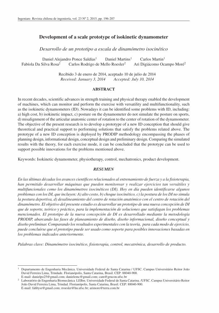
Ingeniare. Revista chilena de ingeniería, vol. 23 Nº 2, 2015, pp. 196-207
Development of a scale prototype of isokinetic dynamometer
Desarrollo de un prototipo a escala de dinamómetro isocinético
Daniel Alejandro Ponce Saldías1 Daniel Martins1 Carlos Martin1
Fabíola Da Silva Rosa2 Carlos Rodrigo de Mello Roesler2 Ari Digiácomo Ocampo Moré2
Recibido 3 de enero de 2014, aceptado 10 de julio de 2014Received: January 3, 2014 Accepted: July 10, 2014
ABSTRACT
In recent decades, scientific advances in strength training and physical therapy enabled the development of machines, which can monitor and perform the exercise with versatility and multifunctionality, such as the isokinetic dynamometers (ID). Nowadays it can be identified some problems with ID, including: a) high cost, b) isokinetic impact, c) posture on the dynamometer do not simulate the posture on sports, d) misalignment of the articular anatomic center of rotation to the center of rotation of the dynamometer. The objective of the present research is to develop a prototype of a new ID conception that should give theoretical and practical support to performing solutions that satisfy the problems related above. The prototype of a new ID conception is deployed by PRODIP methodology encompassing the phases of planning design, informational design, conceptual design and preliminary design. Comparing the simulated results with the theory, for each exercise mode, it can be concluded that the prototype can be used to support possible innovations for the problems mentioned above.
Keywords: Isokinetic dynamometer, physiotherapy, control, mechatronics, product development.
RESUMEN
En las últimas décadas los avances científicos relacionados al entrenamiento de fuerza y a la fisioterapia, han permitido desarrollar máquinas que pueden monitorear y realizar ejercicios tan versátiles y multifuncionales como los dinamómetros isocinéticos (DI). Hoy en día pueden identificarse algunos problemas con los DI, que incluyen: A) alto costo, b) choque isocinético, c) la postura de los DI no simula la postura deportiva, d) desalineamiento del centro de rotación anatómico con el centro de rotación del dinamómetro. El objetivo del presente estudio es desarrollar un prototipo de una nueva concepción de DI que de soporte, teórico y práctico, para la implementación de soluciones que satisfagan los problemas mencionados. El prototipo de la nueva concepción de DI es desarrollado mediante la metodología PRODIP, abarcando las fases de planeamiento de diseño, diseño informacional, diseño conceptual y diseño preliminar. Comparando los resultados experimentales con la teoría, para cada modo de ejercicio, puede concluirse que el prototipo puede ser usado como soporte para posibles innovaciones basadas en los problemas indicados anteriormente.
Palabras clave: Dinamómetro isocinético, fisioterapia, control, mecatrónica, desarrollo de producto.
1 Departamento de Engenharia Mecânica. Universidade Federal de Santa Catarina / UFSC. Campus Universitário Reitor João David Ferreira Lima, Trindade. Florianópolis, Santa Catarina, Brasil. CEP: 88040-900.
E-mail: [email protected]; [email protected]; [email protected] Laboratório de Engenharia Biomecânica LEBm. Universidade Federal de Santa Catarina. /UFSC. Campus Universitário Reitor
João David Ferreira Lima, Trindad. Florianópolis, Santa Catarina, Brasil. CEP: 88040-900. E-mail: [email protected]; [email protected]; [email protected]
Ponce, Martins, Martin, Da Silva, De Mello and Ocampo: Development of a scale prototype of isokinetic dynamometer
197
INTRODUCTION
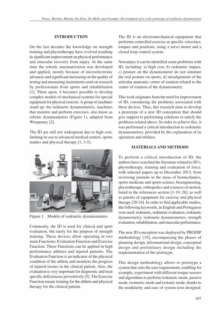
On the last decades the knowledge on strength training and physiotherapy have evolved resulting in significant improvement on physical performance and muscular recovery from injury. At the same time the robotic automatization was developed and applied, mostly because of microelectronic advances and significant increasing on the quality of testing and measuring instruments used on research by professionals from sports and rehabilitation [1]. There upon, it becomes possible to develop complex models of mechanical systems for special equipment for physical exercise. A group of machines stand up: the isokinetic dynamometers, machines that monitor and perform exercises, also know as robotic dynamometers (Figure 1), adapted from Wimpenny [2].
The ID are still not widespread due to high cost, limiting its use to advanced medical centers, sports studies and physical therapy [1, 3-5].
Figure 1. Models of isokinetic dynamometers.
Commonly, the ID is used for clinical and sport evaluation, but rarely for the purpose of strength training. These devices allow operating in two main Functions: Evaluation Function and Exercise Function. These Functions can be applied in high performance athletes and injured patients. The Evaluation Function is an indicator of the physical condition of the athlete and monitors the progress of injured tissues in the clinical patient. Also, the evaluation is very important for diagnostic and treat specific deficiencies preventively [5]. The Exercise Function means training for the athlete and physical therapy for the clinical patient.
The ID is an electromechanical equipment that performs controlled exercise at specific velocities, torques and positions, using a servo motor and a closed loop control system.
Nowadays it can be identified some problems with ID, including: a) high cost, b) isokinetic impact, c) posture on the dynamometer do not simulate the real posture on sports, d) misalignment of the articular anatomic center of rotation related to the center of rotation of the dynamometer.
This work originates from the need for improvement of ID, considering the problems associated with these devices. Thus, this research aims to develop a prototype of a new ID conception that should give support to performing solutions to satisfy the problems related above. In order to achieve this, it was performed a critical introduction to isokinetic dynamometers, provided by the explanation of its operation and utilities.
MATERIALS AND METHODS
To perform a critical introduction of ID, the authors have searched the literature related to ID’s, physiotherapy, training and evaluation of force, with selected papers up to December 2013, from reviewing journals in the areas of biomechanics, sports medicine and sports science, bioengineering, physiotherapy, orthopedics and sciences of motion, listed in the references section [1-19, 26], as well as patents of equipment for exercise and physical therapy [20-24]. In order to find applicable studies, the following keywords, in English and Portuguese were used: isokinetic, isokinetic evaluation, isokinetic dynamometry, isokinetic dynamometers, strength evaluation, rehabilitation, and muscular performance.
The new ID conception was deployed by PRODIP methodology [19], encompassing the phases of planning design, informational design, conceptual design and preliminary design including the implementation of the prototype.
This design methodology allows to prototype a system that suits the user requirements, enabling for example, experiment with different torque sensors and algorithms to perform isokinetic mode, passive mode, isometric mode and isotonic mode, thanks to the modularity and ease of system tests designed.
Ingeniare. Revista chilena de ingeniería, vol. 23 Nº 2, 2015
198
This prototype also allows proposing and testing solutions to problems on the existing equipment.
ISOKINETIC DYNAMOMETER’S STATE OF ART
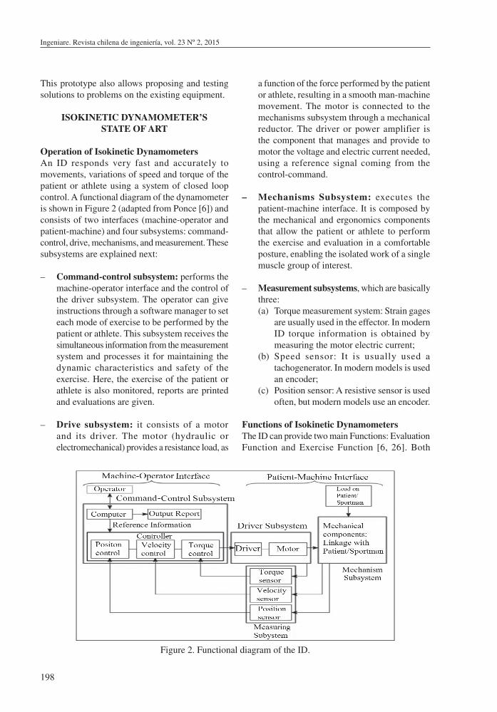
Operation of Isokinetic DynamometersAn ID responds very fast and accurately to movements, variations of speed and torque of the patient or athlete using a system of closed loop control. A functional diagram of the dynamometer is shown in Figure 2 (adapted from Ponce [6]) and consists of two interfaces (machine-operator and patient-machine) and four subsystems: command-control, drive, mechanisms, and measurement. These subsystems are explained next:
– Command-control subsystem: performs the machine-operator interface and the control of the driver subsystem. The operator can give instructions through a software manager to set each mode of exercise to be performed by the patient or athlete. This subsystem receives the simultaneous information from the measurement system and processes it for maintaining the dynamic characteristics and safety of the exercise. Here, the exercise of the patient or athlete is also monitored, reports are printed and evaluations are given.
– Drive subsystem: it consists of a motor and its driver. The motor (hydraulic or electromechanical) provides a resistance load, as
a function of the force performed by the patient or athlete, resulting in a smooth man-machine movement. The motor is connected to the mechanisms subsystem through a mechanical reductor. The driver or power amplifier is the component that manages and provide to motor the voltage and electric current needed, using a reference signal coming from the control-command.
– Mechanisms Subsystem: executes the patient-machine interface. It is composed by the mechanical and ergonomics components that allow the patient or athlete to perform the exercise and evaluation in a comfortable posture, enabling the isolated work of a single muscle group of interest.
– Measurement subsystems, which are basically three:(a) Torque measurement system: Strain gages
are usually used in the effector. In modern ID torque information is obtained by measuring the motor electric current;
(b) Speed sensor: It is usually used a tachogenerator. In modern models is used an encoder;
(c) Position sensor: A resistive sensor is used often, but modern models use an encoder.
Functions of Isokinetic DynamometersThe ID can provide two main Functions: Evaluation Function and Exercise Function [6, 26]. Both
Figure 2. Functional diagram of the ID.
Ponce, Martins, Martin, Da Silva, De Mello and Ocampo: Development of a scale prototype of isokinetic dynamometer
199
Functions are applied in healthy athletes and in patients with injuries. Evaluation Function serves as an indicator of the physical state of the athlete, and monitors the evolution of injured tissues on patient to help identifying different pathologies [7-9]. Exercise Function means training to the athlete and physiotherapy to the patient. There is evidence of improvement on muscle strength in different populations after isokinetic training [10-12].
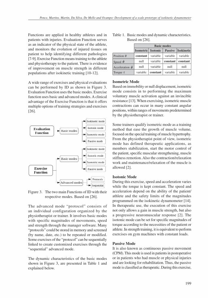
A wide range of exercises and physical evaluations can be performed by ID as shown in Figure 3. Evaluation Function uses the basic modes. Exercise function uses basic and advanced modes. A clinical advantage of the Exercise Function is that it offers multiple options of training strategies and exercises [26].
Figure 3. The two main Functions of ID with their respective modes. Based on [26].
The advanced mode “protocol” consists of an individual configuration organized by the physiotherapist or trainer. It involves basic modes with specific magnitudes of movements, speed and strength through the manager software. Many “protocols” could be stored in memory and screened (by name, date, etc.) to be repeated or modified. Some exercises of the “protocol” can be sequentially linked to create customized exercises through the “sequential” advanced mode.
The dynamic characteristics of the basic modes shown in Figure 3, are presented in Table 1 and explained below.
Table 1. Basic modes and dynamic characteristics. Based on [26].
Basic modes
Isometric Isotonic Passive Isokinetic
Position θ constant variable variable variable
Speed &θ null variable constant constant
Acceleration &&θ null variable null null
Torque τ variable constant variable variable
Isometric ModeBased on immobility or null displacement, isometric mode consists in to performing the maximum voluntary muscle activation against an invincible resistance [13]. When exercising, isometric muscle contractions can occur in many constant angular positions, within ranges of movements predetermined by the physiotherapist or trainer.
Some trainers qualify isometric mode as a training method that ease the growth of muscle volume, focused on the special training of muscle hypertrophy. From the physiotherapist point of view, isometric mode has defined therapeutic applications, as members stabilization, start the motor control of the patient, specific muscular strengthening, muscle stiffness remotion. Also the contraction/relaxation work and maintenance/relaxation of the muscle is allowed [2].
Isotonic ModeDuring this exercise, speed and acceleration varies while the torque is kept constant. The speed and acceleration depend on the ability of the patient/athlete and the safety limits of the magnitudes programmed on the isokinetic dynamometer [14]. In therapeutic use, the execution of this exercise not only allows a gain in muscle strength, but also a progressive neuromuscular response [2]. The isotonic mode can be set for specific magnitudes of torque according to the necessities of the patient or athlete. In strength training, it is equivalent to perform exercises on gym machines with constant loads.
Passive ModeIt is also known as continuous passive movement (CPM). This mode is used in patients in postoperative or in patients who had muscle or physical injuries and are looking for rehabilitation. Thus, the passive mode is classified as therapeutic. During this exercise,
Ingeniare. Revista chilena de ingeniería, vol. 23 Nº 2, 2015
200
the patient’s articulation is submitted to a movement with a low and constant speed.
The benefits of the passive mode are: increase of soft tissue elasticity, short familiarization time with the equipment and improve muscle motor control [14].
Isokinetic ModeThe isokinetic mode consists of performing muscular contractions, concentric and eccentric with a predefined speed that remains constant during the main part of movement [13], except on initial and final stages. The concentric contraction causes a shortening of the muscle during contraction, provoking an approximation of the joint segments [2]. The eccentric contraction causes an elongation of the muscle during contraction, causing a distancing of the joint segments [2].
The isokinetic term must be reserved, therefore, to designate a type of muscular action that accompanies a constant angular movement on one articulation [15]. The isokinetic contraction can only be done by special electromechanical equipment, with a control system, which the isokinetic machine responds in form of resistance directly proportional to the force exerted by the person.
The indications for performing this kind of evaluation and exercise, refers to the agonist/antagonist muscular balance (muscle performing the movement/muscle opposing the movement), and the difference between the muscular groups from one side compared to their contralateral side (muscles on the left side compared to the right side). The clinical applications of this mode are, for example: Resistance Exercises, Submaximal and Maximal Resistance, Resistance Training or Endurance Training and Motion Control of the Patient in addition to physical assessment.
Problems related to Isokinetic DynamometersNowadays, some problems related to ID are known, which consideration is pivotal for the future improvement of these equipments. The mains problems are [2, 6, 13, 16-18, 26]:
– High cost: the isokinetic allows performing evaluation, training and physiotherapy, but these equipments are less known due the high cost, limiting its use to medical centers and studies; then the evaluation and training are
usually performed in different places, therefore the continuous monitoring is impaired.
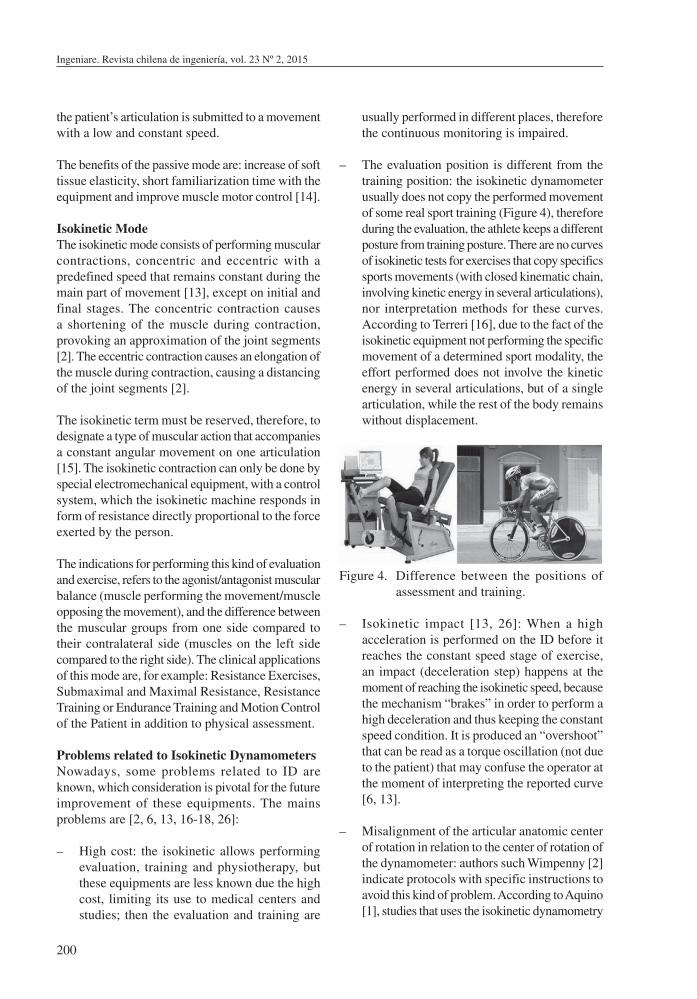
– The evaluation position is different from the training position: the isokinetic dynamometer usually does not copy the performed movement of some real sport training (Figure 4), therefore during the evaluation, the athlete keeps a different posture from training posture. There are no curves of isokinetic tests for exercises that copy specifics sports movements (with closed kinematic chain, involving kinetic energy in several articulations), nor interpretation methods for these curves. According to Terreri [16], due to the fact of the isokinetic equipment not performing the specific movement of a determined sport modality, the effort performed does not involve the kinetic energy in several articulations, but of a single articulation, while the rest of the body remains without displacement.
Figure 4. Difference between the positions of assessment and training.
– Isokinetic impact [13, 26]: When a high acceleration is performed on the ID before it reaches the constant speed stage of exercise, an impact (deceleration step) happens at the moment of reaching the isokinetic speed, because the mechanism “brakes” in order to perform a high deceleration and thus keeping the constant speed condition. It is produced an “overshoot” that can be read as a torque oscillation (not due to the patient) that may confuse the operator at the moment of interpreting the reported curve [6, 13].
– Misalignment of the articular anatomic center of rotation in relation to the center of rotation of the dynamometer: authors such Wimpenny [2] indicate protocols with specific instructions to avoid this kind of problem. According to Aquino [1], studies that uses the isokinetic dynamometry
Ponce, Martins, Martin, Da Silva, De Mello and Ocampo: Development of a scale prototype of isokinetic dynamometer
201
with several purposes often presents conflicting results, that is because differences at the subject positioning related to the evaluated articulations. The alignment process must be strict, since alignment errors may turn into low reliability and low repeatability reading data for the same patient or athlete [17-18].
– Other problems that were manifested on interviews with experts in the field during the execution of this work were [26]: appearance of looseness in bearings with short time of use, low robustness of the structure, patient/athlete accommodation on the equipment bench, electronic problems due the environment humidity and ergonomic problems at shoulder and hip.
In this context, the development of a new design is proposed. This proposal consists in a mechatronic system for algorithm and architecture test, that serves for the development of equipment technology applied to the performing of therapeutic and sports exercises.
This new design must allow to perform the functions available on ID, but in order to know better the technologies that will allow improving the current systems.
DESIGN OF ISOKINETIC DYNAMOMETER
To model, simulate and prototype the new conception it is used the process of product development PRODIP [19] until the preliminary design stage. Thus, the structure has four major stages:
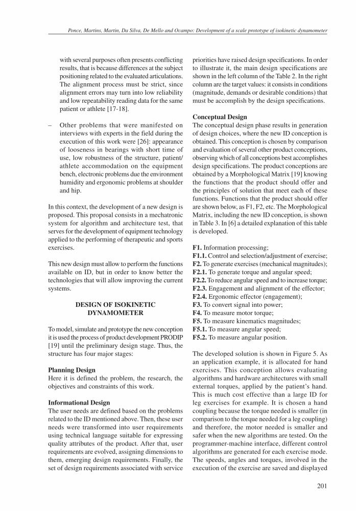
Planning DesignHere it is defined the problem, the research, the objectives and constraints of this work.
Informational DesignThe user needs are defined based on the problems related to the ID mentioned above. Then, these user needs were transformed into user requirements using technical language suitable for expressing quality attributes of the product. After that, user requirements are evolved, assigning dimensions to them, emerging design requirements. Finally, the set of design requirements associated with service
priorities have raised design specifications. In order to illustrate it, the main design specifications are shown in the left column of the Table 2. In the right column are the target values: it consists in conditions (magnitude, demands or desirable conditions) that must be accomplish by the design specifications.
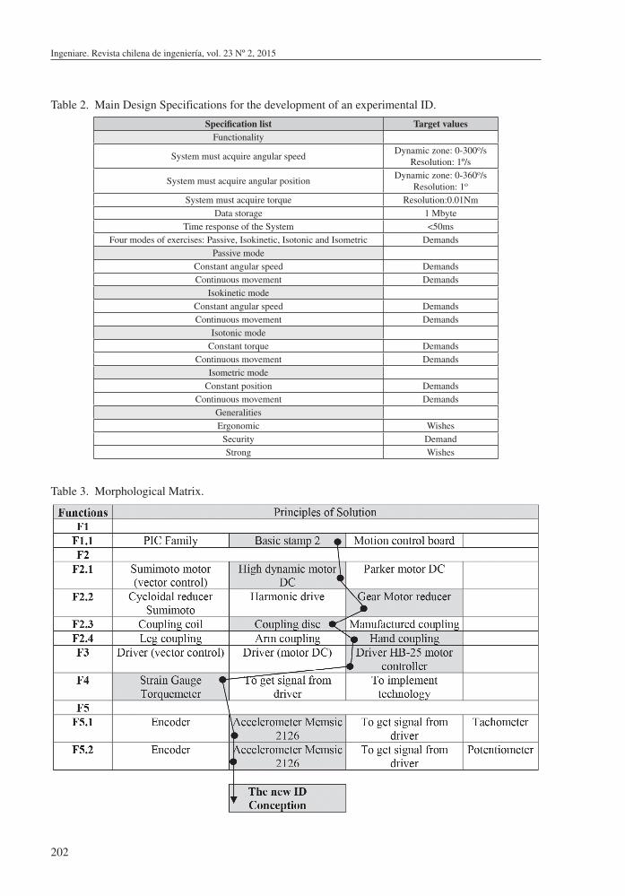
Conceptual DesignThe conceptual design phase results in generation of design choices, where the new ID conception is obtained. This conception is chosen by comparison and evaluation of several other product conceptions, observing which of all conceptions best accomplishes design specifications. The product conceptions are obtained by a Morphological Matrix [19] knowing the functions that the product should offer and the principles of solution that meet each of these functions. Functions that the product should offer are shown below, as F1, F2, etc. The Morphological Matrix, including the new ID conception, is shown in Table 3. In [6] a detailed explanation of this table is developed.
F1. Information processing;F1.1. Control and selection/adjustment of exercise;F2. To generate exercises (mechanical magnitudes);F2.1. To generate torque and angular speed;F2.2. To reduce angular speed and to increase torque;F2.3. Engagement and alignment of the effector;F2.4. Ergonomic effector (engagement);F3. To convert signal into power;F4. To measure motor torque;F5. To measure kinematics magnitudes;F5.1. To measure angular speed;F5.2. To measure angular position.
The developed solution is shown in Figure 5. As an application example, it is allocated for hand exercises. This conception allows evaluating algorithms and hardware architectures with small external torques, applied by the patient’s hand. This is much cost effective than a large ID for leg exercises for example. It is chosen a hand coupling because the torque needed is smaller (in comparison to the torque needed for a leg coupling) and therefore, the motor needed is smaller and safer when the new algorithms are tested. On the programmer-machine interface, different control algorithms are generated for each exercise mode. The speeds, angles and torques, involved in the execution of the exercise are saved and displayed
Ingeniare. Revista chilena de ingeniería, vol. 23 Nº 2, 2015
202
Table 2. Main Design Specifications for the development of an experimental ID.
Specification list Target valuesFunctionality
System must acquire angular speedDynamic zone: 0-300o/s
Resolution: 1º/s
System must acquire angular positionDynamic zone: 0-360o/s
Resolution: 1o
System must acquire torque Resolution:0.01NmData storage 1 Mbyte
Time response of the System <50msFour modes of exercises: Passive, Isokinetic, Isotonic and Isometric Demands
Passive modeConstant angular speed DemandsContinuous movement Demands
Isokinetic modeConstant angular speed DemandsContinuous movement Demands
Isotonic modeConstant torque Demands
Continuous movement DemandsIsometric mode
Constant position DemandsContinuous movement Demands
GeneralitiesErgonomic Wishes
Security DemandStrong Wishes
Table 3. Morphological Matrix.
Ponce, Martins, Martin, Da Silva, De Mello and Ocampo: Development of a scale prototype of isokinetic dynamometer
203
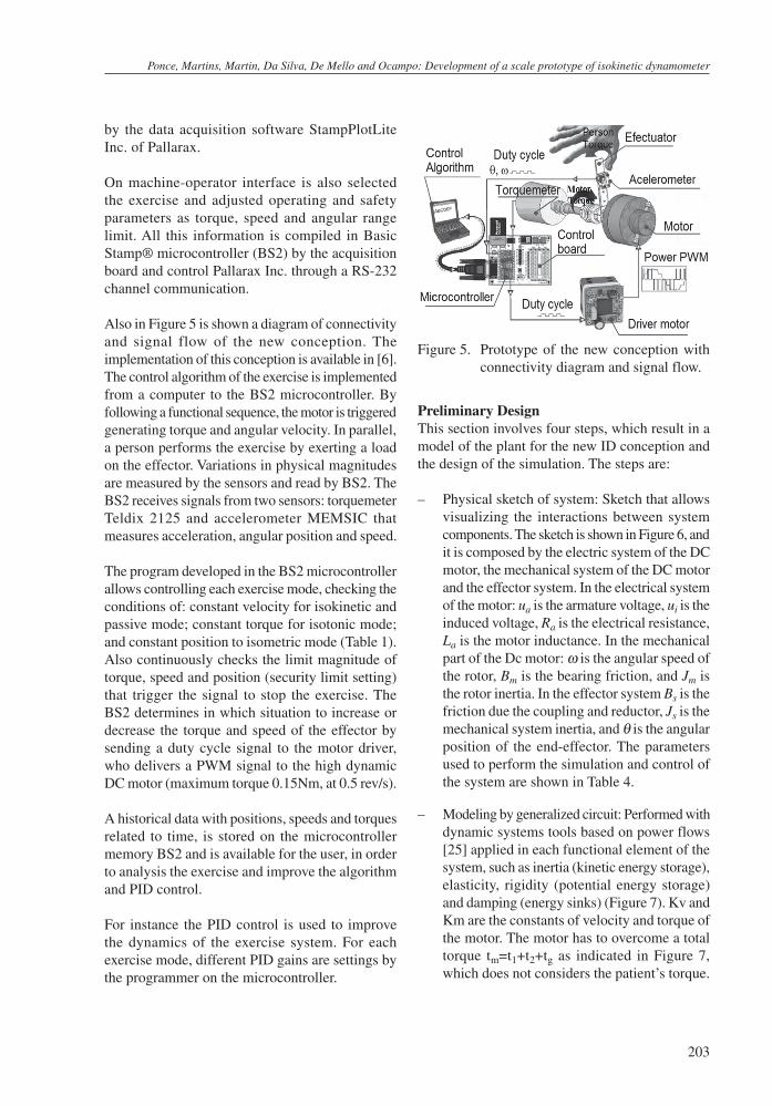
by the data acquisition software StampPlotLite Inc. of Pallarax.
On machine-operator interface is also selected the exercise and adjusted operating and safety parameters as torque, speed and angular range limit. All this information is compiled in Basic Stamp® microcontroller (BS2) by the acquisition board and control Pallarax Inc. through a RS-232 channel communication.
Also in Figure 5 is shown a diagram of connectivity and signal flow of the new conception. The implementation of this conception is available in [6]. The control algorithm of the exercise is implemented from a computer to the BS2 microcontroller. By following a functional sequence, the motor is triggered generating torque and angular velocity. In parallel, a person performs the exercise by exerting a load on the effector. Variations in physical magnitudes are measured by the sensors and read by BS2. The BS2 receives signals from two sensors: torquemeter Teldix 2125 and accelerometer MEMSIC that measures acceleration, angular position and speed.
The program developed in the BS2 microcontroller allows controlling each exercise mode, checking the conditions of: constant velocity for isokinetic and passive mode; constant torque for isotonic mode; and constant position to isometric mode (Table 1). Also continuously checks the limit magnitude of torque, speed and position (security limit setting) that trigger the signal to stop the exercise. The BS2 determines in which situation to increase or decrease the torque and speed of the effector by sending a duty cycle signal to the motor driver, who delivers a PWM signal to the high dynamic DC motor (maximum torque 0.15Nm, at 0.5 rev/s).
A historical data with positions, speeds and torques related to time, is stored on the microcontroller memory BS2 and is available for the user, in order to analysis the exercise and improve the algorithm and PID control.
For instance the PID control is used to improve the dynamics of the exercise system. For each exercise mode, different PID gains are settings by the programmer on the microcontroller.
Preliminary DesignThis section involves four steps, which result in a model of the plant for the new ID conception and the design of the simulation. The steps are:
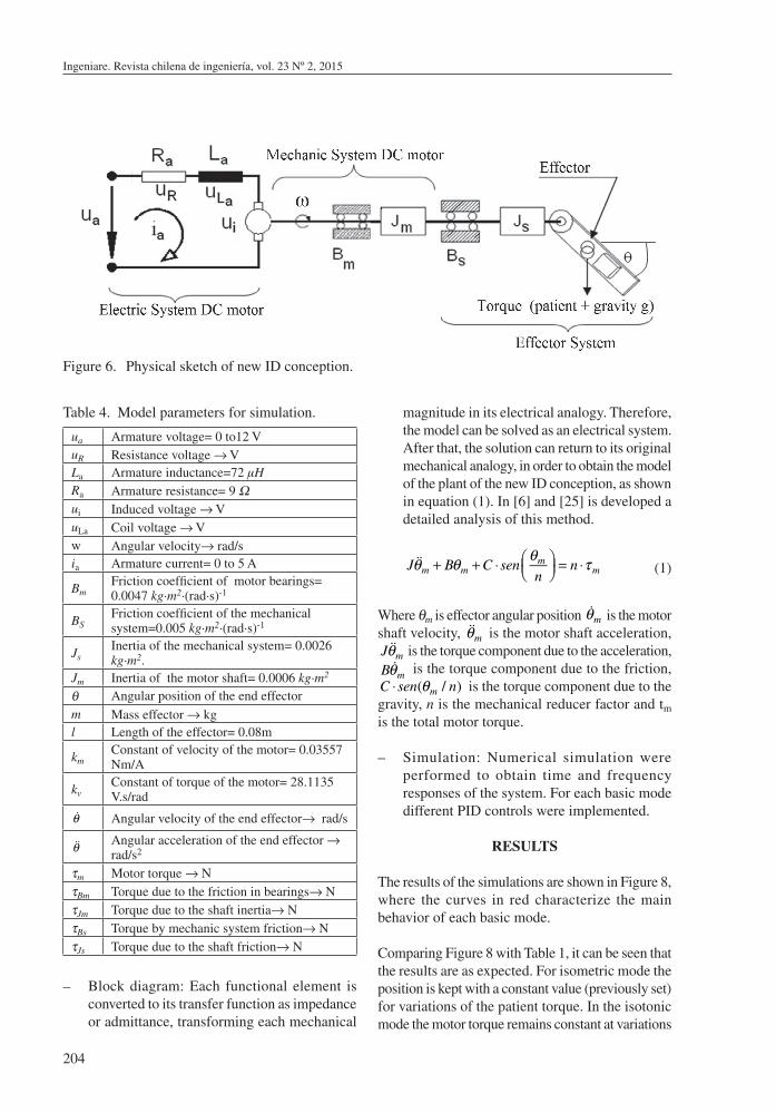
– Physical sketch of system: Sketch that allows visualizing the interactions between system components. The sketch is shown in Figure 6, and it is composed by the electric system of the DC motor, the mechanical system of the DC motor and the effector system. In the electrical system of the motor: ua is the armature voltage, ui is the induced voltage, Ra is the electrical resistance, La is the motor inductance. In the mechanical part of the Dc motor: ω is the angular speed of the rotor, Bm is the bearing friction, and Jm is the rotor inertia. In the effector system Bs is the friction due the coupling and reductor, Js is the mechanical system inertia, and θ is the angular position of the end-effector. The parameters used to perform the simulation and control of the system are shown in Table 4.
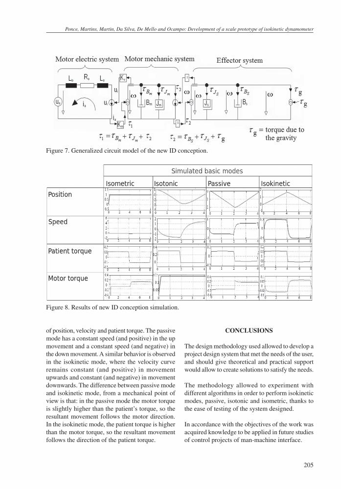
– Modeling by generalized circuit: Performed with dynamic systems tools based on power flows [25] applied in each functional element of the system, such as inertia (kinetic energy storage), elasticity, rigidity (potential energy storage) and damping (energy sinks) (Figure 7). Kv and Km are the constants of velocity and torque of the motor. The motor has to overcome a total torque tm=t1+t2+tg as indicated in Figure 7, which does not considers the patient’s torque.
Figure 5. Prototype of the new conception with connectivity diagram and signal flow.
Ingeniare. Revista chilena de ingeniería, vol. 23 Nº 2, 2015
204
magnitude in its electrical analogy. Therefore, the model can be solved as an electrical system. After that, the solution can return to its original mechanical analogy, in order to obtain the model of the plant of the new ID conception, as shown in equation (1). In [6] and [25] is developed a detailed analysis of this method.
J &&θm + Bθm +C ⋅sen θmn
⎛⎝⎜
⎞⎠⎟ = n ⋅τm (1)
Where θm is effector angular position &θm is the motor shaft velocity, &&θm is the motor shaft acceleration, J &&θm is the torque component due to the acceleration, B &θm is the torque component due to the friction, C ⋅sen(θm / n) is the torque component due to the gravity, n is the mechanical reducer factor and tm
is the total motor torque.
– Simulation: Numerical simulation were performed to obtain time and frequency responses of the system. For each basic mode different PID controls were implemented.
RESULTS
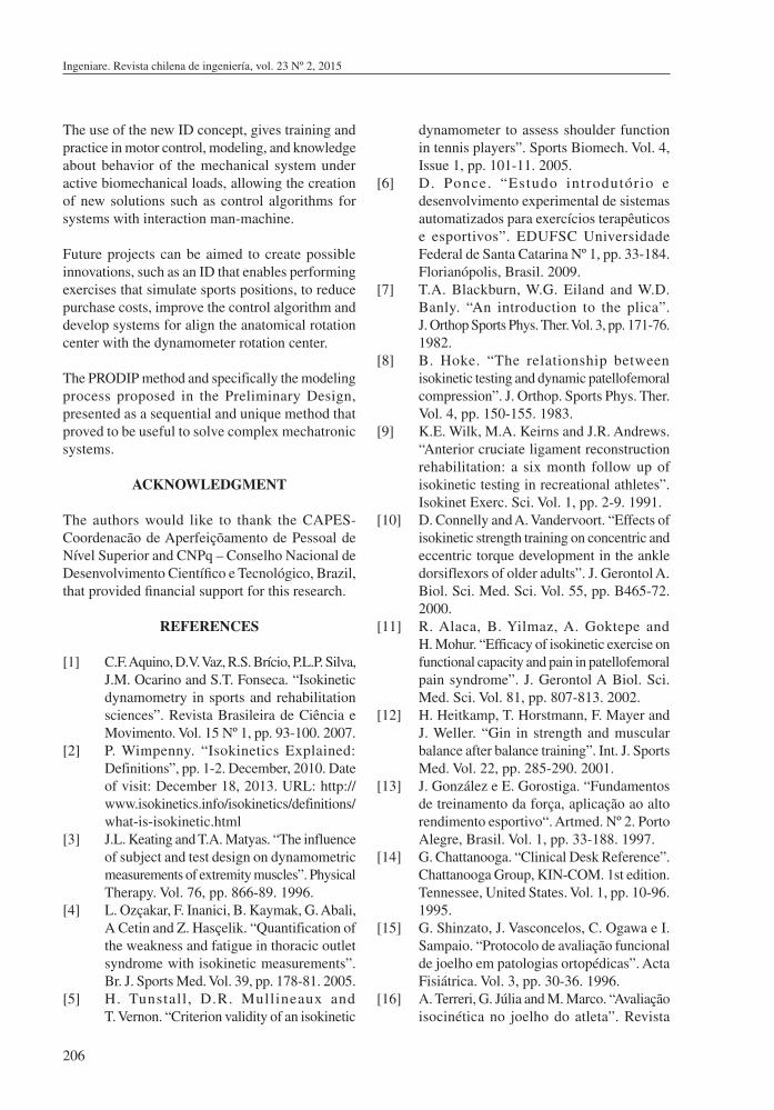
The results of the simulations are shown in Figure 8, where the curves in red characterize the main behavior of each basic mode.
Comparing Figure 8 with Table 1, it can be seen that the results are as expected. For isometric mode the position is kept with a constant value (previously set) for variations of the patient torque. In the isotonic mode the motor torque remains constant at variations
Figure 6. Physical sketch of new ID conception.
Table 4. Model parameters for simulation.
ua Armature voltage= 0 to12 VuR Resistance voltage → VLa Armature inductance=72 µHRa Armature resistance= 9 Ωui Induced voltage → VuLa Coil voltage → Vw Angular velocity→ rad/sia Armature current= 0 to 5 A
BmFriction coefficient of motor bearings= 0.0047 kg∙m2∙(rad∙s)-1
BSFriction coefficient of the mechanical system=0.005 kg∙m2∙(rad∙s)-1
JsInertia of the mechanical system= 0.0026 kg∙m2.
Jm Inertia of the motor shaft= 0.0006 kg∙m2
θ Angular position of the end effectorm Mass effector → kgl Length of the effector= 0.08m
kmConstant of velocity of the motor= 0.03557 Nm/A
kvConstant of torque of the motor= 28.1135 V.s/rad
&θ Angular velocity of the end effector→ rad/s
&&θ Angular acceleration of the end effector → rad/s2
τm Motor torque → NτBm Torque due to the friction in bearings→ NτJm Torque due to the shaft inertia→ NτBs Torque by mechanic system friction→ NτJs Torque due to the shaft friction→ N
– Block diagram: Each functional element is converted to its transfer function as impedance or admittance, transforming each mechanical
Ponce, Martins, Martin, Da Silva, De Mello and Ocampo: Development of a scale prototype of isokinetic dynamometer
205
CONCLUSIONS
The design methodology used allowed to develop a project design system that met the needs of the user, and should give theoretical and practical support would allow to create solutions to satisfy the needs.
The methodology allowed to experiment with different algorithms in order to perform isokinetic modes, passive, isotonic and isometric, thanks to the ease of testing of the system designed.
In accordance with the objectives of the work was acquired knowledge to be applied in future studies of control projects of man-machine interface.
Figure 7. Generalized circuit model of the new ID conception.
of position, velocity and patient torque. The passive mode has a constant speed (and positive) in the up movement and a constant speed (and negative) in the down movement. A similar behavior is observed in the isokinetic mode, where the velocity curve remains constant (and positive) in movement upwards and constant (and negative) in movement downwards. The difference between passive mode and isokinetic mode, from a mechanical point of view is that: in the passive mode the motor torque is slightly higher than the patient’s torque, so the resultant movement follows the motor direction. In the isokinetic mode, the patient torque is higher than the motor torque, so the resultant movement follows the direction of the patient torque.
Figure 8. Results of new ID conception simulation.
Ingeniare. Revista chilena de ingeniería, vol. 23 Nº 2, 2015
206
The use of the new ID concept, gives training and practice in motor control, modeling, and knowledge about behavior of the mechanical system under active biomechanical loads, allowing the creation of new solutions such as control algorithms for systems with interaction man-machine.
Future projects can be aimed to create possible innovations, such as an ID that enables performing exercises that simulate sports positions, to reduce purchase costs, improve the control algorithm and develop systems for align the anatomical rotation center with the dynamometer rotation center.
The PRODIP method and specifically the modeling process proposed in the Preliminary Design, presented as a sequential and unique method that proved to be useful to solve complex mechatronic systems.
ACKNOWLEDGMENT
The authors would like to thank the CAPES-Coordenacão de Aperfeiçõamento de Pessoal de Nível Superior and CNPq – Conselho Nacional de Desenvolvimento Científico e Tecnológico, Brazil, that provided financial support for this research.
REFERENCES
[1] C.F. Aquino, D.V. Vaz, R.S. Brício, P.L.P. Silva, J.M. Ocarino and S.T. Fonseca. “Isokinetic dynamometry in sports and rehabilitation sciences”. Revista Brasileira de Ciência e Movimento. Vol. 15 Nº 1, pp. 93-100. 2007.
[2] P. Wimpenny. “Isokinetics Explained: Definitions”, pp. 1-2. December, 2010. Date of visit: December 18, 2013. URL: http://www.isokinetics.info/isokinetics/definitions/what-is-isokinetic.html
[3] J.L. Keating and T.A. Matyas. “The influence of subject and test design on dynamometric measurements of extremity muscles”. Physical Therapy. Vol. 76, pp. 866-89. 1996.
[4] L. Ozçakar, F. Inanici, B. Kaymak, G. Abali, A Cetin and Z. Hasçelik. “Quantification of the weakness and fatigue in thoracic outlet syndrome with isokinetic measurements”. Br. J. Sports Med. Vol. 39, pp. 178-81. 2005.
[5] H. Tunstall, D.R. Mullineaux and T. Vernon. “Criterion validity of an isokinetic
dynamometer to assess shoulder function in tennis players”. Sports Biomech. Vol. 4, Issue 1, pp. 101-11. 2005.
[6] D. Ponce. “Estudo introdutório e desenvolvimento experimental de sistemas automatizados para exercícios terapêuticos e esportivos”. EDUFSC Universidade Federal de Santa Catarina Nº 1, pp. 33-184. Florianópolis, Brasil. 2009.
[7] T.A. Blackburn, W.G. Eiland and W.D. Banly. “An introduction to the plica”. J. Orthop Sports Phys. Ther. Vol. 3, pp. 171-76. 1982.
[8] B. Hoke. “The relationship between isokinetic testing and dynamic patellofemoral compression”. J. Orthop. Sports Phys. Ther. Vol. 4, pp. 150-155. 1983.
[9] K.E. Wilk, M.A. Keirns and J.R. Andrews. “Anterior cruciate ligament reconstruction rehabilitation: a six month follow up of isokinetic testing in recreational athletes”. Isokinet Exerc. Sci. Vol. 1, pp. 2-9. 1991.
[10] D. Connelly and A. Vandervoort. “Effects of isokinetic strength training on concentric and eccentric torque development in the ankle dorsiflexors of older adults”. J. Gerontol A. Biol. Sci. Med. Sci. Vol. 55, pp. B465-72. 2000.
[11] R. Alaca, B. Yilmaz, A. Goktepe and H. Mohur. “Efficacy of isokinetic exercise on functional capacity and pain in patellofemoral pain syndrome”. J. Gerontol A Biol. Sci. Med. Sci. Vol. 81, pp. 807-813. 2002.
[12] H. Heitkamp, T. Horstmann, F. Mayer and J. Weller. “Gin in strength and muscular balance after balance training”. Int. J. Sports Med. Vol. 22, pp. 285-290. 2001.
[13] J. González e E. Gorostiga. “Fundamentos de treinamento da força, aplicação ao alto rendimento esportivo“. Artmed. Nº 2. Porto Alegre, Brasil. Vol. 1, pp. 33-188. 1997.
[14] G. Chattanooga. “Clinical Desk Reference”. Chattanooga Group, KIN-COM. 1st edition. Tennessee, United States. Vol. 1, pp. 10-96. 1995.
[15] G. Shinzato, J. Vasconcelos, C. Ogawa e I. Sampaio. “Protocolo de avaliação funcional de joelho em patologias ortopédicas”. Acta Fisiátrica. Vol. 3, pp. 30-36. 1996.
[16] A. Terreri, G. Júlia and M. Marco. “Avaliação isocinética no joelho do atleta”. Revista
Ponce, Martins, Martin, Da Silva, De Mello and Ocampo: Development of a scale prototype of isokinetic dynamometer
207
brasileira de medicina do esporte. Vol. 7, pp. 37-45. 2001.
[17] T. Houweling and M. Hamzeh. “Does knee joint alignment with the axis of the isokinetic dynamometer affect peak torque?”. Isokinet Exerc. Sci. Vol. 18, pp. 217-21. 2010.
[18] D. Scoramuzza, R. Axtell and R. Thiel. “Effect of knee joint alignment on isokinetic torque production during leg extension and flexion exercise”. Med. Sci. Sports Exerc. Vol. 22, pp. 190-198. 2010.
[19] N. Back, A. Ogliari, A. Dias and J. Silva. “Projeto integrado de produtos”. Manole. 1st edition. São Paulo, Brasil. Vol. 1, pp. 22-124. 2008.
[20] M. Boettcher. “Exercise and monitoring machine”. Google Patents. 21. Patent number U.S.: 4565368. United States. 1983.
[21] J. Perrine. “Isokinetic exercise process and apparatus”. Google Patents. Patent number U.S.: 3465592. United States. 1969.
[22] R. Ruggles. “Isokinetic exercise device with speed control”. Google Patents. Patent number U.S.: 4374588. United States. 1983.
[23] E.M. Mattox, E.D. Mask and J.D. Beeding. “Isokinetic exerciser”. Google Patents. Patent number U.S.: 4385760. United States. 1983.
[24] S.M. Sagedahl, J.W. German and R.M. Wolfe. “Isokinetic exercise apparatus and method”. Google Patents. Patent number U.S.: 4592545. United States. 1986.
[25] K. Janschek. “Mechatronic Systems Design: Methods, Models, Concepts”. Springer. 1. Berlin, Germany. 2012. ISBN: 9783642175305.
[26] D. Ponce, C.A. Martin, M.C. Andrade and D. Martins. “Conceitualização e análise crítica dos dinamômetros isocinéticos”. Revista Brasileira de Biomecânica. Vol. 12 Nº 23, pp. 65-74. Junio 2011. ISSN: 1518-8191.