Embed Size (px)
Citation preview

SSC01-X1-7
David Dowen 1 15th Annual/USU Conference on Small Satellites
Development of a Reusable, Low-Shock Clamp Band Separation System for Small Spacecraft Release Applications
David Dowen, Scott Christiansen
Starsys Research Corporation Boulder, Colorado
303-530-1925; [email protected]; [email protected]
Andrew Peffer Air Force Research Laboratory
Albuquerque, New Mexico 505-853-6322; [email protected]
Abstract. In small spacecraft, the proximity of sensitive components to release systems has led to the need for low-shock spacecraft release systems. Marmon band systems are often desirable for their flight history, structural capability, and reliability. Until recently, only pyrotechnically released clamp bands were readily available. The clamp band system described in ths paper reduces shock in two ways: it eliminates shock typically associated with pyrotechnic release devices as well as utilizing a release device that reduces the shock associated with the rapid release of the preload strain energy. Patented Fast Acting Shockless Separation Nut (FASSN) technology is utilized to convert strain energy stored in the system into rotational energy of a flywheel. Early FASSN devices were designed for discrete point applications and were somewhat large and massive. Additional development of the FASSN device has reduced the size and weight to enable the use of the technology in a medium sized (12 to 24 inch diameter) clamp band system. This paper describes the overall design, performance, and initial test results for the FASSN-based, non-pyrotechnic, low-shock clamp band release system.
Introduction General Background Most small spacecraft operators are in pursuit of low cost launch options. The size of the spacecraft and the modest launch requirements often make secondary launch positions attractive options. Secondary positions on unmanned launch vehicle payload adapters and small payload platforms in the shuttle bay are the two basics options for launch of small spacecraft. As the number of small spacecraft to be launched has increased and as more launchers have offered secondary payload positions, the need for standardized interfaces has been identified. Clamp band systems seem to be the best choice for retention and release in these systems. Clamp band systems have been used for separation of spacecraft from launch vehicles on numerous flights. These systems offer excellent structural properties; very simple, reliable operation; and extensive flight history. The systems are typically released by operation of a pyrotechnic bolt cutter to cut a bolt that holds the clamp band in its preloaded state. This system has high strength and stiffness when clamped and releases quickly (typically <50 msec.) when operated. Both of these operational characteristics
are considered very important during launch and separation during a flight mission. FASSN Background FASSN technology was developed initially for use in a discrete point release mechanism. The three primary advantages of the technology are: • Non-pyrotechnic, fast release • Shock reduction by conversion of stored strain
energy into rotational energy • Resettablity Non-pyrotechnic, Fast Release While pyrotechnic devices are common on spacecraft and their use has an extensive history, there are several drawbacks to pyrotechnics • Their explosive nature makes their storage and
handling difficult and cumbersome. • They typically generate quite energetic shock spectra
(typical accelerations in the 3000 to 5000 g range) during operation.
• The hardware that flies cannot be tested for mechanical function.
To meet the fast response time, but eliminate the above drawbacks, the FASSN was designed to rely on a shape memory alloy (SMA) wire trigger. A SMA wire trigger was sized to utilize an electrical pulse very similar to that of a pyrotechnic device. The SMA trigger allowed fast

David Dowen 2 15th Annual/USU Conference on Small Satellites
response, elimanated source shock, and allowed for reset and repeated operation of all of the components of the device without breaking configuration. Shock Reduction Often the largest source of shock in a deployment system is the rapid release of stored strain energy. A release system requires robust structural properties during launch and prior to operation. To eliminate joint gapping and structural deadband, the interface must be preloaded to levels greater than those expected during launch. This preload results in strain energy stored in the release elements as well as the sections of the structure in the preloaded load path. Historically bolt cutters or separation nuts release this strain energy in a very short time, typically less than .5 millisecond. Rapid release of energy tends to lead to higher shock. A second aspect of this stored strain energy release is that it occurs within the structural elements of the system and, hence, the shock has a good transmission path to nearby components. The FASSN technology utilizes simple mechanical elements to increase the time over which the strain energy is released to significantly reduce strain-energy-induced structural shock. The system is based on a high-lead, backdrivable thread and a flywheel. A flywheel with the high-lead thread is held in place for launch. A mating high-lead thread is attached to the deployable portion of the device. When the interface is mated and preloaded, the high-lead thread creates a torque that wants to rotate the flywheel. When the flywheel is released, the flywheel “spins-up” as the deployable element is extracted. The inertia of the flywheel and the length of engagement of the high-lead thread can be adjusted to provide the optimal amount of energy transfer and release time for the system. In a typical application, the load drop time for a FASSN is in the 2 to 5 millisecond range compared with less than .5 milliseconds for a bolt cutter. This increase in load drop time reduces source shock by significant amounts. Release shock in a FASSN system is typically below 400 g’s. Resettability Pyrotechnics are one time use devices. While some of the mechanical components can be reused, the initiator and secondary charge (if required) must be replaced after each operation. The FASSN utilizes SMA wire triggers that respond to a pyrotechnic-type electrical signal, but can be reused without replacement. After operation, the release system can be re-mated, the release mechanism can be reset and
the system can be preloaded. In this reset process, no replacement or refurbishment is required. This capability allows for complete system test and reset without breaking flight configuration. A high degree of confidence in the operability and reliability can be achieved with a resettable system. Clamp Band System To utilize the FASSN release technology and establish a standardized release mechanism/interface the release system as described in this paper was developed. The system is based on a marmon clamp band approach. The system has two adapter rings with integral marmon ring features. A one-piece band with multiple shoes is used to clamp the adapter rings. A release mechanism based on FASSN technology is used to preload and then release the band. Integral kick-off springs are included for spacecraft separation and releasable electrical connectors allow power transfer and communication prior to separation.
Design Description The clamp band system has been designed to be used for multiple applications while maintaining as many common elements as possible. Of the two applications considered at this time, one application was for the Nanosat program, which is intended to be a standard platform for small satellites to be launched aboard NASA’s shuttle. The second was for ESPA (EELV Secondary Payload Adapter), which is a standard for secondary launch positions on the payload adapter for Lockheed Martin’s EELV (Evolved Expendable Launch Vehicle) . Clamp Band Nanosat The first application for the clamp band system was for the Nanosat program. Figure 1 shows the basic configuration of the launch platform. Several spacecraft are stacked in two stacks and attached with lightweight release systems. Both stacks are attached to a common plate with the FASSN clamp band systems. The plate is then attached in the shuttle bay using a pyrotechnic-based clamp band system called SHELS (Shuttle Hitchhiker Experiment Launch System). The release sequence begins by separating the plate and satellites (as a unit) from the shuttle bay. The plate and satellites remain together in orbit until the shuttle has landed. Both stacks are then simultaneously released from the main plate. Individual spacecraft are then separated from each other as required for their target orbits. Figure 2 illustrates the general geometry for the Nanosat application.

David Dowen 3 15th Annual/USU Conference on Small Satellites
Stack Separation Plane ( 2
3CS-3(Petey)
3CS-2(Ralphie)
3CS-1(Sparky)
IONF-3(USUSat)
IONF-2(Dawgstar)
IONF-1(HokieSat)
Stack Separation System (SSS)MSDS Baseplate
x (AFT)
z
MSDS
SHELS
Stack Interface Plane (2 PL)
SHELS/MSDS Plane
SHELS Adapter Ring
Intersatellite Separation4 PL
Intersatellite Separation"Lightband"(Planetary Systems, Inc.)4 PL
2.5 degrees cant(per Stack)
Three Corner SatNanosat Stack
ION-FNanosat Stack
Low shock release system forStack Separation
Intersatellite Separation System“Lightband”(Planetary Systems, Inc.)4PL
Figure 1. Nanosat launch configuration. This approach utilizes two stacks of small spacecraft on a single releasable platform.
Figure 2. Nanosat configuration of clamp band system.
ESPA The ESPA application involves attaching small spacecraft radially around a payload adapter ring on the EELV launcher. Figure 3 shows the basic shape of the adapter ring. Up to six small satellites can be attached to the adapter with clamp band systems. The spacecraft are then released individually as required for their target orbits. Figure 4 shows the structural components and general interface geometry for the ESPA application.
Figure 3. Six position ESPA payload adapter ring.
Common elements between these systems were the basic clamping and release system that could be qualified and used as a basis for both systems. Differing requirements included: • Relative separation velocity requirements for specific
spacecraft and orbital requirements • Connector channel requirements • Interface bolt patterns

David Dowen 4 15th Annual/USU Conference on Small Satellites
The character of the requirements led to a design that is based on a singe, common release approach and could be adapted for the variable requirements listed above.
Figure 4. Primary structural components for the ESPA application.
Clamp Band Design Features Figure 5 shows the clamp band system in its stowed, preloaded configuration. The main structural components are the Spacecraft Adapter Plate and the Launch Vehicle Adapter Plate (labeled MSDS Adapter Plate in Figure 6). The adapter plates are machined from aluminum and can be sized and shaped to meet specific stiffness, load, and interface requirements. This design is adaptable for clamp band diameters from approximately 9 inches up to 24 inches. Shown in figure 5 is the one-piece aluminum clamp band. The clamp band holds the clamping shoes against the adapter plates at the separation plane. The one-piece band allows for self-deployment and eliminates the need for retraction springs. Five simple band-catching features (Band Retention System) catch and retain the band after release. The band and retention system provide a very clean band-separation dynamic and eliminate shoe rebound. Four kick-off springs are utilized to achieve spacecraft separation velocities. The springs can be sized to achieve .5 ft/sec to 2 ft/sec separation velocities with tip-off rates less than .5 degrees/sec. The electrical connectors are also shown and can be selected to provide the number of channels required for a specific launch. The initial baseline is for a total of 38 channels across the release interface (two 19 pin connectors).
Figure 6 shows both sides of the clamp band system shown in their deployed, separated configuration. Both views show the separation interface between the adapter plates. Release Mechanism Figure 7 shows the release mechanism area of the clamp band system. Key elements of the release mechanism are the band retaining bolts, which attach the ends of the clamp band with the release mechanism, and the release mechanism itself. The mechanism is based on FASSN technology, but utilizes a flywheel with two female high-lead threads. One thread is a right-hand thread, the other a left-hand thread. The bolts both thread into the flywheel in a manner similar to a turnbuckle. The mechanism is then reset to prevent flywheel rotation. The exposed ends of the bolts are threaded to mate with the ends of the band. Preloading of the band is completed by tightening the nuts and monitoring the system load with the Strainsert instrumented bolt. Figure 8 shows the internal, flywheel-retention components of the release mechanism. When the Release Nut (flywheel) is in its latched position with the bolts installed , the notches in the Release Nut line up with the Detents that are retained by slots in the Body. The Wrap Wire is tightly wound around the Body and retains the Detents against the Release Nut. During launch, the Wrap Wire is held in position by the SMA wire trigger assembly and the system remains clamped. Upon release of the Wrap Wire by the trigger, the Wrap Wire unwinds, allowing the Detents to move radially away from the Release Nut. The backdrive torque generated by the preload and the high-lead thread causes the Release Nut to spin and the bolts to be released from the mechanism. Figure 9 shows the SMA trigger assembly in both the latched and released positions. In the latched position, the Lock Arm retains the end of the Wrap Wire and prevents release of the system. The Lock Arm is restrained from rotating by the Release Arm. Redundant SMA wire triggers are attached to the Release Arm. To operate the device, an electrical signal is supplied to either one or both circuits. As the SMA heats and shrinks, it causes rotation of the Release Arm, which in turn allows rotation of the Lock Arm. As the Lock Arm rotates, the Wrap Wire is released.

David Dowen 5 15th Annual/USU Conference on Small Satellites
ReleaseMechanism
Band
Kickoff spring(4 total, 90°apart)
Band RetentionSystem
Positive Energy ElectricalConnector(2 total, 180°apart)
Spacecraft AdapterPlate
Figure 5. Clamp band system with major components identified. System is shown in clamped, preloaded configuration.
MSDS Adapter Plate
ReleaseMechanism
Band
Kickoff spring(4 total, 90°apart)
Band Retention System
Positive Energy ElectricaConnector (2 total, 180°apart)
Spacecraft AdapterPlate
Figure 6. Clamp band system shown separated. Both views show the separation plane of the interface.

David Dowen 6 15th Annual/USU Conference on Small Satellites
ReleaseMechanism
BandRetainingBolt
Band RetainingBolt
SpacecraftAdapterPlate
MSDSAdapterPlate
Band
Anti Torque Feature
Release Mech.Mounting plate
Figure 7. Release mechanism detail view.
Housing
Release Nut
Bearing
DetentBody
Wrap Wire
Reset Ratchet
Wrap WireRetainer
Figure 8. Exploded view of Release Mechanism. Major functional components are identified.
Lock arm
SMA Wire
ReleaseArm
a. Trigger assembly latched b. Trigger assembly unlatched
Figure 9. Two views of the SMA trigger assembly showing major components.
David Dowen 7 15th Annual/USU Conference on Small Satellites
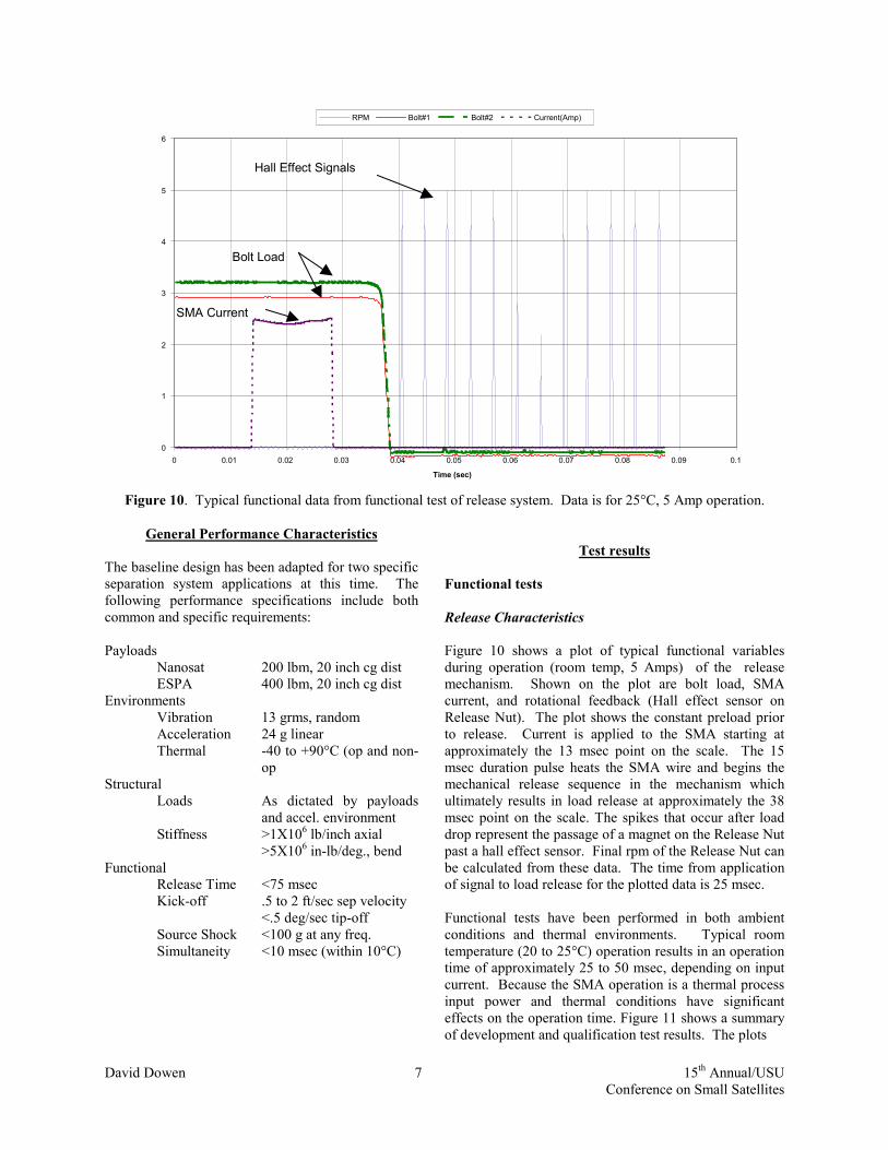
Bolt Load
SMA Current
Hall Effect Signals
0
1
2
3
4
5
6
0 0.01 0.02 0.03 0.04 0.05 0.06 0.07 0.08 0.09 0.1
Time (sec)
RPM Bolt#1 Bolt#2 Current(Amp)
Figure 10. Typical functional data from functional test of release system. Data is for 25°C, 5 Amp operation.
General Performance Characteristics
The baseline design has been adapted for two specific separation system applications at this time. The following performance specifications include both common and specific requirements: Payloads Nanosat 200 lbm, 20 inch cg dist ESPA 400 lbm, 20 inch cg dist Environments Vibration 13 grms, random Acceleration 24 g linear
Thermal -40 to +90°C (op and non-op
Structural Loads As dictated by payloads
and accel. environment Stiffness >1X10⁶ lb/inch axial >5X10⁶ in-lb/deg., bend Functional Release Time <75 msec Kick-off .5 to 2 ft/sec sep velocity <.5 deg/sec tip-off Source Shock <100 g at any freq. Simultaneity <10 msec (within 10°C)
Test results
Functional tests Release Characteristics Figure 10 shows a plot of typical functional variables during operation (room temp, 5 Amps) of the release mechanism. Shown on the plot are bolt load, SMA current, and rotational feedback (Hall effect sensor on Release Nut). The plot shows the constant preload prior to release. Current is applied to the SMA starting at approximately the 13 msec point on the scale. The 15 msec duration pulse heats the SMA wire and begins the mechanical release sequence in the mechanism which ultimately results in load release at approximately the 38 msec point on the scale. The spikes that occur after load drop represent the passage of a magnet on the Release Nut past a hall effect sensor. Final rpm of the Release Nut can be calculated from these data. The time from application of signal to load release for the plotted data is 25 msec. Functional tests have been performed in both ambient conditions and thermal environments. Typical room temperature (20 to 25°C) operation results in an operation time of approximately 25 to 50 msec, depending on input current. Because the SMA operation is a thermal process input power and thermal conditions have significant effects on the operation time. Figure 11 shows a summary of development and qualification test results. The plots

David Dowen 8 15th Annual/USU Conference on Small Satellites
0
0.01
0.02
0.03
0.04
0.05
0.06
0.07
0.08
-60 -40 -20 0 20 40 60 80 100
Temperature (deg C)
Tim
e (s
ec)
3 amp 5 amp
Figure 11. Release time dependence on applied current and environmental temperature.
illustrate the dependence of the total release time on input current and operating temperature. Source Shock Generation Accelerometers were mounted on the upper flange of the clamp band structure adjacent to the release device. Accelerometer data were recorded at this location to assess shock levels generated during release. A plot of the shock spectrum is shown in Figure 12. Peak generated shock was measured at 26 g’s at a frequency of 4300 Hz.
Nanosat SRS output (Q=10)
0.001
0.01
0.1
1
10
100
100 1000 10000
Natural Frequency (Hz)
Peak
Acc
el (G
)
PositiveNegative
Figure 12. Source shock during operation.
Release Velocity / Tip-off Release velocity and tip-off rates were measured during functional tests using a gravity off-loaded (suspended) mass simulator. High speed video was used to observe band release dynamics and initial motion of the mass simulator. Release velocities of .6 ft/sec and tip-off of .3 deg/sec were achieved. Because offloading of a mass simulator is imperfect and the technique utilized may have had potentially significant effects on the motion of the mass simulator, additional tests are scheduled to characterize these aspects of separation. Tests are to be performed on NASA’s KC-135 zero-g test facility to obtain better separation dynamics test results. Structural Tests A primary function of the clamp band system is to provide structure between the launch vehicle and the spacecraft. Static and dynamic structural tests were performed to characterize and qualify the system to the flight requirements.

David Dowen 9 15th Annual/USU Conference on Small Satellites
Static Structural Tests Figure 13 shows the clamp band system setup in the static test fixture. Loads were applied to the test fixture adapter that replicated the directions and locations of equivalent loads at the spacecraft cg. Loads were calculated based on spacecraft mass and quasistatic acceleration calculations. At this time tests have been performed at the Nanosat load requirements that have resulted in loads of 4800 lbf being applied at the equivalent spacecraft cg position (20 inches above the separation system/spacecraft interface) in both plus and minus directions in three orthogonal axes. Strain gages and deflections in the system were monitored to look for permanent deformation and /or shifts in position.
Figure 13. Clamp band system assembled in structural test fixture.
Static testing was also performed to establish the stiffness of the clamp band and adapter plates. Stiffness of the system has been measured as follows: Axial 1X10⁶ lb/inch tension 2X10⁷ lb/inch compression Bending 5.2X10⁶ in-lb/degree minimum Deflections were measured at the interface plane on the top of the clamp band structure. Dynamic Structural Tests Figure 14 shows the clamp band system and a spacecraft simulator on a vibration table. The spacecraft simulator is a structural/mass simulator of the Stanford satellite to be launched using this system. The mass of the simulator was 78 lbs with a cg at 19 inches off the interface plane. Random vibration at 12.9 grms was performed to simulate launch conditions. A sine burst test at 23.8 g was used to simulate linear accelerations. The clamp
band system was not affected as a result of these tests and subsequent functional tests showed that the release system operated nominally. Future dynamic tests will be used to characterize the system at levels closer to the maximum capacity of the design (more massive spacecraft models).
Figure 14. Stanford mass simulator supported by clamp
band system on vibration table.
Overall Results 1. Overall development and test results show that the
clamp band system meets the rquirements for both the Nanosat and ESPA applications.
2. The low shock generated during release can allow spacecraft designers and operators more latitude in instrument placement as well as reduction of shock analysis and testing requirements.
3. The system is adaptable to a large number of variations that may result from specific small satellite mission launch requirements.
Future Design Improvements • Higher kick-off rates require that the band release
and clear the ejection path of the deployable side of the interface more quickly than it does in the current design. Band dynamics need to be analyzed and improved to enable higher kick-off rates.
• Axial stiffness can be improved by optimizing the load path at the ring interface. In the current design

David Dowen 10 15th Annual/USU Conference on Small Satellites
localized bending in the interface area limits axial stiffness (in the current size) to 1X10⁶ lb/inch
• The current design has not been completely optimized for mass. Additional analysis should yield results that will reduce the overall mass of the system.
Future Applications and Adaptations • A 9 inch diameter system has been discussed
with AFRL for use with a constellation of very small (10 kg) spacecraft
• An organization has expressed interest in a 13 inch clamp band system for potential use for separation of a small kick motor
• Additional shock reduction for the spacecraft can be achieved by adding a shock isolation system to the adapter. An integrated FASSN clamp band/shock isolation system is currently being considered and worked on at CSA Engineering.
• Additional trigger technologies are being developed at Starsys that will be able to expand the thermal range of the mechanism.
• Features to impart spin to the spacecraft during separation have been proposed and are being considered as a future option.
Acknowledgements
Funding for this development program was supplied by the Air Force Research Laboratory through a Small Business Innovative Reaearch (SBIR) grant. Portions of the design and development of the clamp band system were performed in collaboration with Saab-Ericsson Aerospace in accordance with a 10 year partnership agreement.