Embed Size (px)
Citation preview

JOURNAL OF AEROSPACE COMPUTING, INFORMATION, AND COMMUNICATIONVol. 4, August 2007
Development of a Real-time Onboard and Ground StationSoftware System for a UAV Helicopter�
Miaobo Dong∗ , Ben M. Chen† , Guowei Cai‡ , Kemao Peng§
National University of Singapore, Singapore 117576
DOI: 10.2514/1.26408
We report in this paper the development of a real-time software system for an unmannedaerial vehicle (UAV) helicopter, which consists of an embedded computer onboard and aground station served by a laptop. The software system for the onboard computer per-forms multiple tasks including data acquisition and measurement, servo driving, automaticflight control implementation, communications and data logging. The system for the groundstation gives a flexible graphical interface monitoring the real-time status of the UAV heli-copter. We present the frameworks and structures of the onboard and ground station systems.The onboard system employs a framework of multiple task threads with each thread beingassigned to perform a specific task. Management and time scheduling for task threadstogether with the detailed implementation of automatic flight control laws are the mainfocuses of the onboard software system. A behavior-based architecture is designed to addresstask scheduling and event disposal for automatic control. A hierarchical and componentialstructure is developed to integrate multiple control laws and perform various helicopterbehaviors. The ground station software system employs a two-layer framework, i.e., datatransferring in background and data visualization in foreground.A variety of views are devel-oped to display in-flight data received from the UAV helicopter in different forms includinga 3D monitoring panel, which displays real-time data in 3D on the ground station.
I. Introduction
IN recent years, research on unmanned vehicles has gained much attention worldwide.1 Objects like unmannedaircraft, underwater exploiters, satellites and intelligent robotics are widely investigated as they have potential
applications in both military and civil domains. They are developed to be capable of working autonomously withouthuman pilot. Challenge is that they need to deal with various situations arisen in much complicated and uncertainenvironment, such as unexpected obstacles, enemies attacking and device failures. Besides, they are required tocommunicate with technical personnel in the ground station. Consideration on a wide range of factors needs to betaken. Control systems for the unmanned vehicles are required to integrate not only basic input-output control laws,but also high-level functionalities for decision making and task scheduling. Software systems for unmanned vehiclesare required to perform tasks from hardware driving to the management of device operation, and from traditionalinput-output control law implementation to task scheduling and event disposal. A number of works have beenpublished in the literature on the system architecture, control method and software implementation for unmanned
Received 09 July 2006; revision received 5 December 2006; accepted for publication 10 July 2007. Copyright © 2007 bythe American Institute of Aeronautics and Astronautics, Inc. All rights reserved. Copies of this paper may be made for personalor internal use, on condition that the copier pay the $10.00 per-copy fee to the Copyright Clearance Center, Inc., 222 RosewoodDrive, Danvers, MA 01923; include the code 1542-9423/04 $10.00 in correspondence with the CCC.∗ Research Fellow, Department of Electrical & Computer Engineering, [email protected]† Professor, Department of Electrical & Computer Engineering, [email protected], corresponding author‡ PhD Student, Department of Electrical & Computer Engineering, [email protected]§ Research Scientist, Temasek Laboratories, [email protected]�This work is partially supported by the Defense Science and Technology Agency (DSTA), the Republic of Singapore.
933

DONG, CHEN, CAI, AND PENG
Fig. 1 The HeLion UAV helicopter.
vehicles.2–8 An introduction of onboard software implementation for a model helicopter is presented by Kottmann,9
in which onboard tasks such as communications, data logging and control are briefly described. Wills et. al.3 developa so-called open control platform (OCP) with reconfigurability and interoperability for complex dynamic systems andpresent a demonstration prototype of simulation platform for an unmanned helicopter based on the common objectrequest broker architecture (CORBA). A practical solution of software implementation for a fixed-wing UAV is givenby Jang and Tomlin,10 which uses inter-process communications and synchronization to schedule onboard tasks anduses OCP3 for ground station software. Nevertheless, there is still much work left to explore new technologies ofsoftware implementation for unmanned vehicles.
In this paper, we aim to develop a comprehensive software system that can be used to serve as a platform formodeling and implementation of automatic flight control for a real UAV helicopter, which consists of a small-scalebasic helicopter with all necessary accessories onboard and a ground station served by a laptop. Figure 1 showsour UAV helicopter, HeLion, developed at the National University of Singapore. The basic helicopter is about 1.41meter in length and 4.85 kilogram in weight. An embedded computer system is attached at the lower portion ofHeLion. The onboard system is composed of a PC/104 computer (CRR3-650, Lippert), an inertial measurement unit(IMU) (NAV420, Crossbow), a data acquisition board (DIAMOND-MM-32-AT, Diamond), a sonar chip (UPK 500,SNT SENSORTECHNIK AG), a wireless communication board (IM-500X008, FreeWave), a set of servo drivers(HBC101, Pontech), and other necessary components.11
The automatic flight control system is directly implemented on the onboard system. During flight tests, the IMU,sonar and data acquisition board collect measurement signals of current state of the UAV helicopter. The output signalsof these devices are then utilized to generate automatic control signals to drive appropriate servo motors. The onboardsoftware system is built to be capable of performing multiple tasks including hardware driving, device management,automatic control, communications and data logging. It is also to realize multiform control laws and perform variousflight actions such as hovering, lifting, forward and backward flying. Our software framework offers good flexibilityand extensibility for new modules and control functionalities. The ground station laptop is equipped with wirelessmodem, which receives data from and sends commands to the HeLion onboard system. Another function of theground station is to provide a graphical user interface helping users monitor and command the UAV helicopter.
The onboard software system is developed using a real-time operating system, QNX Neutrino, which providesreliable support for high precision timer and synchronization operation. The ground station software system runs ona commercial operating system, Windows XP Professional, which offers an excellent environment for developing
934
DONG, CHEN, CAI, AND PENG
graphical user interfaces. A framework of multiple threads is employed for the onboard system to perform multipletasks, i.e., to operate hardware like the IMU, data acquisition board and servo system, to log all kinds of data inflying process, to communicate with the ground station, and to implement automatic control algorithms. Each threadperforms one specific task. Time table for both software and hardware processing is designed and tested. To implementautomatic control, a behavior-based architecture is employed. In such architecture, the operation of the helicopteris organized in a variety of behaviors. A hierarchical and componential structure is used to execute these behaviorsand to integrate multiple control algorithms. Our ground station system has two layers, namely, data transferring inbackground and user interface in foreground, which consists of a curve view of data in coordination style and a 3Dview simulating the attitude and motion of the actual helicopter.
The content of this paper is organized as follows. Section II presents the onboard software system, in whichthe implementation of task management and automatic control are given together with some source codes. Theframework and implementation of the ground station software are documented in Section III, in which the graphicalinterface and 3D view development are discussed. Section IV addresses a variety of practical issues involved in theprocess of software development together with some actual flight test results. Finally, we draw some concludingremarks in Section V.
II. Onboard SystemWe present in this section the development of the framework of the onboard system, which contains a number
of task blocks dealing with specific onboard devices. We demonstrate how these tasks are managed and scheduledthrough a mechanism of multiple threads, and how the automatic flight control is implemented.
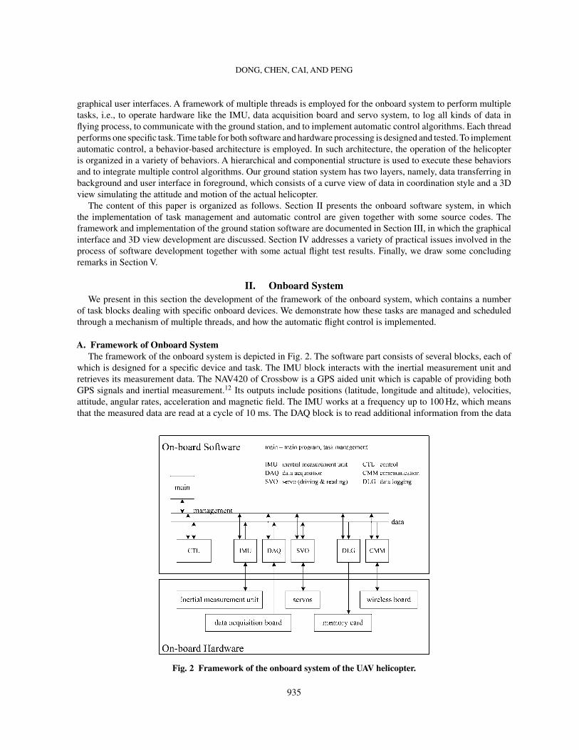
A. Framework of Onboard SystemThe framework of the onboard system is depicted in Fig. 2. The software part consists of several blocks, each of
which is designed for a specific device and task. The IMU block interacts with the inertial measurement unit andretrieves its measurement data. The NAV420 of Crossbow is a GPS aided unit which is capable of providing bothGPS signals and inertial measurement.12 Its outputs include positions (latitude, longitude and altitude), velocities,attitude, angular rates, acceleration and magnetic field. The IMU works at a frequency up to 100 Hz, which meansthat the measured data are read at a cycle of 10 ms. The DAQ block is to read additional information from the data
Fig. 2 Framework of the onboard system of the UAV helicopter.
935

DONG, CHEN, CAI, AND PENG
acquisition board, such as the rotating speed of the main rotor, the liquid level of the fuel box. The CTL block is toimplement automatic flight control laws. This is the only block that does not interact with hardware, but with theIMU block and the SVO block. During flight tests, it reads the state of the helicopter from global shared data fromthe IMU and performs calculation of control algorithm to generate automatic control signals that drive the servomotors. The upper level tasks such as navigation, task scheduling and plan interpretation can also be integrated intothis block. The SVO block is the servo driving system, which is to drive the helicopter servos and read servo position.Our helicopter servos include aileron servo (roll control), elevator servo (pitch control), auxiliary servo (collectivecontrol) and rudder servo (yaw control). The CMM block is for communications between the onboard system and theground station terminal. A duplex wireless board of bandwidth 115,200 bit per second is used to download in-flightdata of helicopter and upload user commands. The DLG block performs data logging, which is usually consideredas a background task saving all data including measurements and inner states during operations. A 256 M compactflash card is employed as the storage media for the onboard system. We do not choose hard disk because of its sizeand its vulnerability against vibration which is unavoidable on the helicopter. The main block is to manage all tasks.Mechanism of its management and scheduling will be discussed in detail in the next subsection. Exchange of databetween blocks is accomplished by a global shared data scheme, in which all data are centralized.
B. Task ManagementThe task management of all blocks is implemented using the QNX Neutrino real-time operating system, which
supports timers of high-frequency up to a nanosecond level and provides a variety of system functions forsynchronization.13,14 These characteristics are crucial for implementing automatic control laws that require fastresponses.
A scheme of multiple threads is employed to implement these tasks. Every task is performed in a separate thread,called task thread. They are periodically activated at a pre-set rate. In every period, these task threads are scheduledto run in a designed order through a mechanism of synchronization. The mechanism prevents the main thread andother threads from blocking each other. Processing times for different tasks are different. A scheduling table for bothsoftware and hardware processing is designed based on the statistics of test data.
Task scheduling is performed in the main thread. At every period, the main thread sends pulse messages to alltask threads one after another. The pulse message acts as activating signal for the task thread. It wakes up the taskthread to perform work. Programs are developed as follows to implement such mechanism.
main programinitialize task threadsinitialize timerloop {
wait for timer signalread user commandif command is for exit, exit loopsend an activating pulse to task thread 1wait some time for task 1 accomplishmentsend an activating pulse to task thread 2wait some time for task 2 accomplishment…send an activating pulse to task thread n,wait some time for task n accomplishment
}send an exit pulse to task thread 1,send an exit pulse to task thread 2,…send an exit pulse to task thread n.exit main program
task threadloop {
936
DONG, CHEN, CAI, AND PENG
wait for a pulseif pulse is for exit, exit loopdo work…set notification of accomplishment
}exit task thread
A timer is used to schedule the execution process of the main program. The timer emits a pulse signal at everyspecific period to activate task processing. The main program contains a waiting and processing loop. In the loop, themain program waits for a pulse signal from the timer. It keeps idle until a timer signal is captured. Once the signalis captured, the user command is read and executed. The loop will be terminated if an exit command is received.The main function of every cycle is to send activating pulses to task threads in a pre-scheduled order. After all thescheduled task threads are executed, the program returns to the loop and waits for the next timed pulse signal. Thefrequency used in our system is about 20 ms per cycle. When an exit command arrives to terminate the loop, themain program will send exit pulses to every task thread scheduled.
The executions of task threads are carried out in a similar fashion. In the entrance of a task thread loop, it waitsfor a pulse signal from the main program. Once an execution signal is received, all subsequent steps scheduled inthe thread are then executed. The loop is terminated when an exit pulse is received from the main thread. Afterthe thread is successfully processed, a notification signal will be sent to the main program loop. The main programthen proceeds to process the next task thread. The waiting scheme for each task thread gives the thread exclusiveoccupation of the CPU resource and prevents the main program from terminating the thread when it is running.
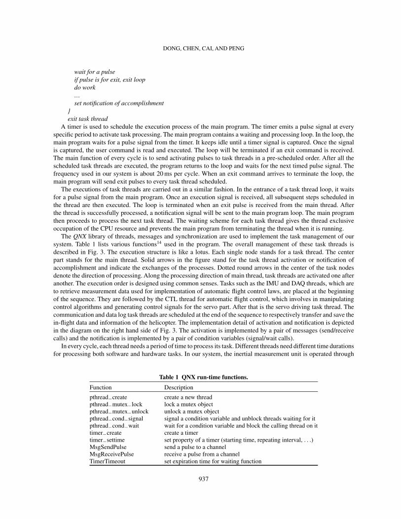
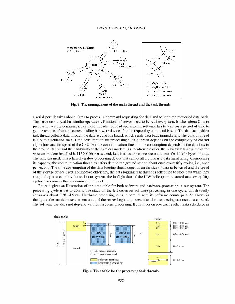
The QNX library of threads, messages and synchronization are used to implement the task management of oursystem. Table 1 lists various functions14 used in the program. The overall management of these task threads isdescribed in Fig. 3. The execution structure is like a lotus. Each single node stands for a task thread. The centerpart stands for the main thread. Solid arrows in the figure stand for the task thread activation or notification ofaccomplishment and indicate the exchanges of the processes. Dotted round arrows in the center of the task nodesdenote the direction of processing. Along the processing direction of main thread, task threads are activated one afteranother. The execution order is designed using common senses. Tasks such as the IMU and DAQ threads, which areto retrieve measurement data used for implementation of automatic flight control laws, are placed at the beginningof the sequence. They are followed by the CTL thread for automatic flight control, which involves in manipulatingcontrol algorithms and generating control signals for the servo part. After that is the servo driving task thread. Thecommunication and data log task threads are scheduled at the end of the sequence to respectively transfer and save thein-flight data and information of the helicopter. The implementation detail of activation and notification is depictedin the diagram on the right hand side of Fig. 3. The activation is implemented by a pair of messages (send/receivecalls) and the notification is implemented by a pair of condition variables (signal/wait calls).
In every cycle, each thread needs a period of time to process its task. Different threads need different time durationsfor processing both software and hardware tasks. In our system, the inertial measurement unit is operated through
Table 1 QNX run-time functions.
Function Description
pthread−create create a new threadpthread−mutex−lock lock a mutex objectpthread−mutex−unlock unlock a mutex objectpthread−cond−signal signal a condition variable and unblock threads waiting for itpthread−cond−wait wait for a condition variable and block the calling thread on ittimer−create create a timertimer−settime set property of a timer (starting time, repeating interval, . . .)MsgSendPulse send a pulse to a channelMsgReceivePulse receive a pulse from a channelTimerTimeout set expiration time for waiting function
937
DONG, CHEN, CAI, AND PENG
Fig. 3 The management of the main thread and the task threads.
a serial port. It takes about 10 ms to process a command requesting for data and to send the requested data back.The servo task thread has similar operations. Positions of servos need to be read every turn. It takes about 8 ms toprocess requesting commands. For these threads, the read operation in software has to wait for a period of time toget the response from the corresponding hardware device after the requesting command is sent. The data acquisitiontask thread collects data through the data acquisition board, which sends data back immediately. The control threadis a pure calculation task. Time consumption for processing such a thread depends on the complexity of controlalgorithms and the speed of the CPU. For the communication thread, time consumption depends on the data flux tothe ground station and the bandwidth of the wireless modem. As mentioned earlier, the maximum bandwidth of thewireless modem installed is 115200 bit per second, i.e., it takes about one second to transfer 14 kilo bytes of data.The wireless modem is relatively a slow processing device that cannot afford massive data transferring. Consideringits capacity, the communication thread transfers data to the ground station about once every fifty cycles, i.e., onceper second. The time consumption of the data logging thread depends on the size of data to be saved and the speedof the storage device used. To improve efficiency, the data logging task thread is scheduled to store data while theyare piled up to a certain volume. In our system, the in-flight data of the UAV helicopter are stored once every fiftycycles, the same as the communication thread.
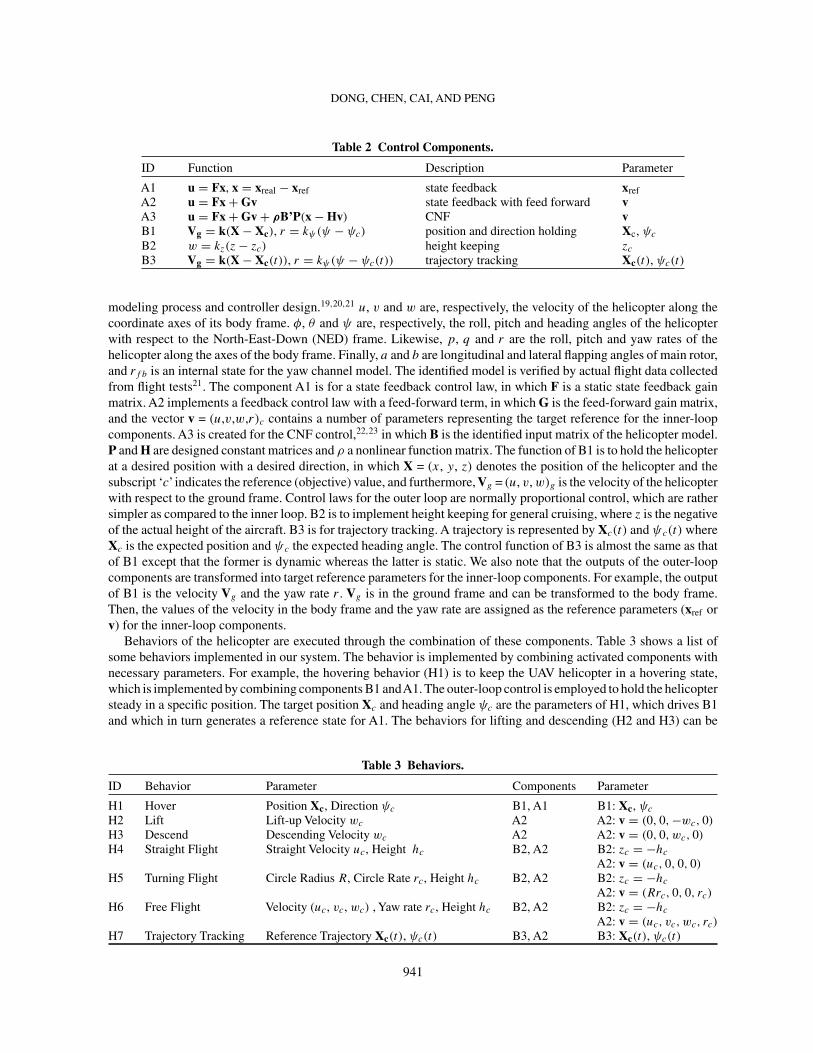
Figure 4 gives an illustration of the time table for both software and hardware processing in our system. Theprocessing cycle is set to 20 ms. The stack on the left describes software processing in one cycle, which totallyconsumes about 0.38∼4.5 ms. Hardware processing runs in parallel with its software counterpart. As shown inthe figure, the inertial measurement unit and the servos begin to process after their requesting commands are issued.The software part does not stop and wait for hardware processing. It continues on processing other tasks scheduled in
Fig. 4 Time table for the processing task threads.
938

DONG, CHEN, CAI, AND PENG
the sequence. When the requested data are ready, they will be read in next cycle. After all the tasks are executed (inabout 4.5 ms), a vacant time block is left in the software, which can be used for additional features developed in thefuture. It is also ideal for the overall software system to keep a low working load of the CPU. The detailed descriptionof software processing is depicted by the stack on the right hand side of Fig. 4, where a list of time consumptions isgiven for all task threads.
C. Implementation of Automatic ControlWith a properly designed automatic controller, the aircraft is able to perform some automatic flight patterns such
as lifting, forward or backward flying in a constant velocity, and flying along a pre-specified trajectory. To perform acomplete task, it is needed to combine a series of these flight patterns or behaviors. For example, a reconnaissance taskmay be accomplished by a series of flight actions such as lifting, flying to the target location, hovering, photo-takingand returning. A behavior-based architecture is employed to organize various behaviors or flight patterns in a plan.In the behavior-based architecture, operation of the unmanned helicopter is composed of behaviors, which form thebasic units of the agent operation. The accomplishment of a task is made up of execution of a series of behaviors.Plans are established to define the organization of these behaviors. A plan consists of a set of basic units, which theUAV helicopter needs to perform, and events upon which these behaviors are triggered. In short, the plan definesa schedule, which specifies the executing time and order of a set of behaviors. Interested readers are referred to arecent work15 for a more detailed description of the behavior-based architecture.
The behavior-based architecture of our UAV helicopter system is given in Fig. 5. It consists of two parts, thetask scheduling block and the control system block. The scheduling block hosts plans for the helicopter. They aredescribed by diagrams with nodes and lines. Each node represents a specific behavior or a sub-plan and each linerepresents an event. Events trigger switching from one behavior to another. Events can be generated through thefollowing three sources: (1) the surrounding environment or hardware situation, such as arisen obstacles, detectedtargets and hardware fault; (2) the judgment on flight state, such as the achievement of control objectives; and (3)a user command. The task scheduling block therefore employs an event-driven mechanism. Based on retrievedinformation of the state and environment, it judges what event had happened and what behavior should be executedin response to the event according to predefined plans. The determined behavior is dispatched to the control systemblock and executed. The task scheduling block is a decision maker or commander, and the control system block isan executor. Actually, the task scheduling block replaces the role of the human pilot in manned aircraft.
The control system block is for the execution of behaviors, i.e., to drive the UAV helicopter to complete certainflight actions specified by the behaviors. Each behavior is implemented for a particular control mechanism. Theoverall control system is designed in a componential and hierarchical structure to integrate multiple control laws andimplement behaviors of different levels. It contains a collection of control components with each component beingprogrammed for a specific control law to generate control signals based on internal information and measurementsignals received. The overall control system is thus implemented with one or a combination of these components.
These control components can be classified into two levels in our design, the inner loop and the outer loop. Theinner loop is designed for attitude control and for driving the helicopter to a steady state. The outer loop is fornavigation, e.g., to guide the UAV helicopter flying to a specific target location in a desired orientation or alonga designated trajectory. Multiple components are allowed in each level to implement different control laws and toperform one control task with different parameters and performance in different situations or for different purposes. Inour system, there is more than one component in both the inner-loop level and outer-loop level. Some behaviors haveto be performed by executing multiple components. Usually, the execution of the outer-loop components requiresthe cooperation of the inner-loop components.
However, it should be noted that the proposed behavior-based architecture is different from the traditional behavior-based architecture16,17,18, which was originally proposed for robotic systems. In the traditional setting, the behaviorsare considered as integral control. In this paper, the behavior is much like a concept standing for an action, a kind ofoperation of an agent, and the control system is considered as a pure behavior executor although it can be hierarchicalas well. Another note is that the scheduler is clearly separated from the control system rather than being one higherlevel in the control system as the sequencer in the traditional behavior-based architectures.
As a practical example, Figure 5 shows the structure of the control system we developed for our UAV helicopter.Three different types of control laws are implemented for the inner loop including state feedback control, state
939

DONG, CHEN, CAI, AND PENG
Fig. 5 Behavior-based architecture.
feedback control with feed-forward and composite nonlinear feedback (CNF) control. They are implemented incomponents labeled A1, A2 and A3. In the outer-loop level, three components labeled B1, B2 and B3 are respectivelydesigned to execute different operations, position and direction holding, height keeping and trajectory tracking. Theouter-loop components need to work together with the inner-loop components. When the outer-loop is activated, itdoes not send control signals directly to the servo system. Instead, it generates a set of control settings or parametersfor the inner-loop components. Descriptions of these components including their functions and parameters are listedin Table 2.
In Table 2, u = (δa , δe, δu, δr) contains the control inputs for aileron, elevator, collective and rudder, respectively.x = (u, v, p, q, φ, θ , a, b, w, r , rf b) is a collection of dynamical state variables of the helicopter identified in
940
DONG, CHEN, CAI, AND PENG
Table 2 Control Components.
ID Function Description Parameter
A1 u = Fx, x = xreal − xref state feedback xrefA2 u = Fx + Gv state feedback with feed forward vA3 u = Fx + Gv + ρB’P(x − Hv) CNF vB1 Vg = k(X − Xc), r = kψ(ψ − ψc) position and direction holding Xc, ψc
B2 w = kz(z − zc) height keeping zc
B3 Vg = k(X − Xc(t)), r = kψ(ψ − ψc(t)) trajectory tracking Xc(t), ψc(t)
modeling process and controller design.19,20,21 u, v and w are, respectively, the velocity of the helicopter along thecoordinate axes of its body frame. φ, θ and ψ are, respectively, the roll, pitch and heading angles of the helicopterwith respect to the North-East-Down (NED) frame. Likewise, p, q and r are the roll, pitch and yaw rates of thehelicopter along the axes of the body frame. Finally, a and b are longitudinal and lateral flapping angles of main rotor,and rf b is an internal state for the yaw channel model. The identified model is verified by actual flight data collectedfrom flight tests21. The component A1 is for a state feedback control law, in which F is a static state feedback gainmatrix. A2 implements a feedback control law with a feed-forward term, in which G is the feed-forward gain matrix,and the vector v = (u,v,w,r)c contains a number of parameters representing the target reference for the inner-loopcomponents. A3 is created for the CNF control,22,23 in which B is the identified input matrix of the helicopter model.P and H are designed constant matrices and ρ a nonlinear function matrix. The function of B1 is to hold the helicopterat a desired position with a desired direction, in which X = (x, y, z) denotes the position of the helicopter and thesubscript ‘c’ indicates the reference (objective) value, and furthermore, Vg = (u, v, w)g is the velocity of the helicopterwith respect to the ground frame. Control laws for the outer loop are normally proportional control, which are rathersimpler as compared to the inner loop. B2 is to implement height keeping for general cruising, where z is the negativeof the actual height of the aircraft. B3 is for trajectory tracking. A trajectory is represented by Xc(t) and ψc(t) whereXc is the expected position and ψc the expected heading angle. The control function of B3 is almost the same as thatof B1 except that the former is dynamic whereas the latter is static. We also note that the outputs of the outer-loopcomponents are transformed into target reference parameters for the inner-loop components. For example, the outputof B1 is the velocity Vg and the yaw rate r . Vg is in the ground frame and can be transformed to the body frame.Then, the values of the velocity in the body frame and the yaw rate are assigned as the reference parameters (xref orv) for the inner-loop components.
Behaviors of the helicopter are executed through the combination of these components. Table 3 shows a list ofsome behaviors implemented in our system. The behavior is implemented by combining activated components withnecessary parameters. For example, the hovering behavior (H1) is to keep the UAV helicopter in a hovering state,which is implemented by combining components B1 andA1. The outer-loop control is employed to hold the helicoptersteady in a specific position. The target position Xc and heading angle ψc are the parameters of H1, which drives B1and which in turn generates a reference state for A1. The behaviors for lifting and descending (H2 and H3) can be
Table 3 Behaviors.
ID Behavior Parameter Components Parameter
H1 Hover Position Xc, Direction ψc B1, A1 B1: Xc, ψc
H2 Lift Lift-up Velocity wc A2 A2: v = (0, 0, −wc, 0)
H3 Descend Descending Velocity wc A2 A2: v = (0, 0, wc, 0)
H4 Straight Flight Straight Velocity uc, Height hc B2, A2 B2: zc = −hc
A2: v = (uc, 0, 0, 0)
H5 Turning Flight Circle Radius R, Circle Rate rc, Height hc B2, A2 B2: zc = −hc
A2: v = (Rrc, 0, 0, rc)
H6 Free Flight Velocity (uc, vc, wc) , Yaw rate rc, Height hc B2, A2 B2: zc = −hc
A2: v = (uc, vc, wc, rc)
H7 Trajectory Tracking Reference Trajectory Xc(t), ψc(t) B3, A2 B3: Xc(t), ψc(t)
941
DONG, CHEN, CAI, AND PENG
implemented by a single inner-loop component A2 by setting either lifting or descending velocity parameter w. Threeheight-keeping flying behaviors (H4–H6) are implemented by the combining B2 and A2. The outer-loop componentB2 is to keep the flight height. The inner-loop component A2 is to control the forward velocity, lateral velocity andyaw rate. The trajectory tracking behavior (H7) is implemented by components B3 and A2. The interactions betweenthe inner- and the outer-loop components are through parameters such as (u, v, w, r). For example, a circle flightbehavior can be implemented by combining (B2, A3) or (B2, A1). Some behaviors are homological, such as lifting(H2) and descending (H3), straight flight (H4), circle flight (H5) and free flight (H6).
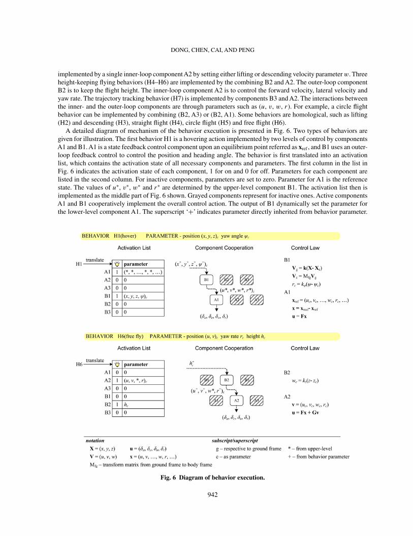
A detailed diagram of mechanism of the behavior execution is presented in Fig. 6. Two types of behaviors aregiven for illustration. The first behavior H1 is a hovering action implemented by two levels of control by componentsA1 and B1. A1 is a state feedback control component upon an equilibrium point referred as xref , and B1 uses an outer-loop feedback control to control the position and heading angle. The behavior is first translated into an activationlist, which contains the activation state of all necessary components and parameters. The first column in the list inFig. 6 indicates the activation state of each component, 1 for on and 0 for off. Parameters for each component arelisted in the second column. For inactive components, parameters are set to zero. Parameter for A1 is the referencestate. The values of u∗, v∗, w∗ and r∗ are determined by the upper-level component B1. The activation list then isimplemented as the middle part of Fig. 6 shown. Grayed components represent for inactive ones. Active componentsA1 and B1 cooperatively implement the overall control action. The output of B1 dynamically set the parameter forthe lower-level component A1. The superscript ‘+’ indicates parameter directly inherited from behavior parameter.
Fig. 6 Diagram of behavior execution.
942
DONG, CHEN, CAI, AND PENG
The superscript ‘*’ indicates parameters determined by the upper-level component. Control laws of B1 and A1 aregiven in the right hand side of the figure. The outer-loop control (B1) performs position and heading angle feedback.The position error is turned to velocity in the ground frame and transformed into values in the body frame. Theerror of the heading angle is transformed into yaw rate. The obtained velocity and yaw rate are then used by theinner-loop control (A1) as the target reference. The behavior H6, in the second portion of the figure, is to perform aheight-keeping flight with a specific forward velocity uc, a lateral velocity vc, a yaw rate rc and a flight height hc.It is translated to an activation list in which A2 and B2 are set to be active. Parameters uc, vc and rc are directlysent to the lower-level component A2 and hc is passed to the higher-level component B2. The parameter wc for A2is dynamically determined by B2. Control laws of A2 and B2 are highlighted in the figure as well. A2 performs astate feedback control action with a feed-forward term. B2 performs a negative feedback using the error between theactual height of the aircraft and the target reference.
Lastly, we note that all of control implementations presented above reside in control task thread (CTL) in thesoftware framework. Like other task threads, it is called to perform task scheduling, behavior execution and controllaw calculation in every processing cycle. In each cycle, the program is executed as in the following.
stage 1: look up plan
check all events linked to current nodeif any event occurs return corresponding behavior and parameterselse return null
stage 2: translate behavior to activation list
if behavior equals H1, set flag A1 and flag B1 on, set corresponding parameterselse if behavior equals H2, set flag A2 on, set corresponding parameterselse if behavior equals H3, . . .
. . .
else do nothing; //behavior is null, doing nothing on flag and parameters, keep current control
stage 3: execute behavior
if flag B3 is on, run B3 functionif flag B2 is on, run B2 functionif flag B1 is on, run B1 functionif flag A3 is on, run A3 functionif flag A2 is on, run A2 functionif flag A1 is on, run A1 function
In the first stage, it looks up the plan, and checks events linked to the current node, as display in the diagram.Occurrence of event is judged on information retrieved from GPS sensor, camera, etc. If a certain event occurs, itwill return a corresponding behavior triggered by this event. Otherwise, no action is taken. In the second stage, thebehavior is translated into a corresponding activation list with necessary parameters. The activation state is controlledby flags for control components. For example, the behavior H1 activates the flag A1 and flag B1 to be turned on.If no behavior is generated from the previous stage, no action will be taken on flags and parameters, which meansthat the system is performing the current control function. In the third stage, the program enters a series of controlcomponent executions. Functions of the control components are run or skipped according to the states of their flags.
III. Ground Station SoftwareThe ground station plays a role as a terminal for end users to monitor and command the UAV helicopter through
the wireless communication channel. In the flight tests, data of the UAV helicopter are transferred from the onboardsystem to the ground station and displayed. The task of the ground station is to provide a friendly and realistic interfacefor users to monitor the process of the flight tests. Different methods of data visualization are to be implemented. Inthis section, we introduce the framework for developing the ground station software system. We particularly highlight
943

DONG, CHEN, CAI, AND PENG
Fig. 7 Framework of the ground station software system.
the development of a 3D view interface, which is capable of transforming the data received from the helicopter intoa realistic 3D view on the ground station.
The framework of the ground station software system is depicted in Fig. 7, which has two layers, i.e., thebackground layer and the foreground layer. Data transferring runs in background. This layer collaborates with theonboard system (i.e., the CMM task thread) through a wireless channel, receiving data from and sending commandsto the onboard system. Two separate threads are created for the receiving and sending actions, respectively. In theprogram, the receiver thread keeps reading the serial port connected to the wireless device and adding received data toshared global storage once they are received. The sender thread keeps waiting for user’s commands and writing it tothe serial port once a command is captured. The read/write operation upon serial port collaborates with correspondingwrite/read operation on the onboard system. The shared global data are the media between the background layer andthe foreground layer. The global data are dynamically updated. The foreground layer consists of a variety of viewsdisplaying the in-flight data. Four kinds of views have been developed in our system up to now, i.e., the state view,curve view, 3D view and command view. The state view shows basic states of the helicopter in a manner of a listof texts. The curve view shows in-flight data in 2D coordination graphs, in which data are generally displayed as afunction of time. The 3D view is to reconstruct the actual motion of the helicopter in a more realistic 3D style.
The ground station software system is run on a laptop with the Windows XP Professional. Such a commercialoperating system provides strong support for the development of user interfaces and many developing tools. VisualC++ 6.0 is employed to develop the ground station software system. In this version, document-view structure based onthe MFC ( Microsoft Foundation Class) library is recommended by Microsoft for application oriented development.24
Our framework uses a similar structure as the MFC. The global shared data are hosted in a document class, in whicha variety of methods for data operation and visiting are integrated. This document class is the kernel of the program,which links all communication threads and functions of the multiple displaying views. The communication threadsreceive data from and send data to it dynamically. Displaying views, as visualization windows of document contents,periodically visit the contents of the document and update their displaying of new data received. A brief descriptionof such a program is given in the following.
document classinit
create communication threads(pass pointer to this document to threads as parameter)create views(pass pointer to this document to these views)create timer
944

DONG, CHEN, CAI, AND PENG
ontimerloop {get pointer to next viewif the pointer is null(end), exit loopcall the updating function (onupdate) of that view}
onusercommandget the user command string inputted by userparse the commandstorage the translated command code and parameter
view classonupdate
get the pointer pointing to the documentget new data in the documentdraw view according to the new data
communication thread 1 (receiver)loop {
read serial port for communicationsif new data received {
storage new data in the document}
}communication thread 2 (sender)
loop {look up to the document if new command capturedif there is new command {
translate command and parameter in telegraphwrite telegraph to communication serial port
}}
The document class has three main member functions. The init function is called to initialize the document andcreate threads, views and updating timer. When threads and views are created, a pointer of the document is passed tothem to link them together. The document itself keeps an array of pointers to these views as well. The timer is finallycreated to send updating signals periodically. The timer message is handled by the member function ontimer. Inevery cycle when the timer message is captured, the ontimer function searches all views linked to the document andcall their updating functions (onupdate) one by one. onusercommand is the user command handling function that isintegrated in the document class. Once the user input a command through some interface items such as a menu or anedit control box, this member function is called. It first gets the string the user has inputted, then parses and translatesit in an internal representation carrying command code and parameters. The translated code and parameters are thenput in the document to be sent to the onboard system by the communication thread. Views are defined in the viewclasses with respective types. A common method is use to define all view classes. The onupdate member function iscalled every time when the data displays need to be updated, mostly when new data are added to the document. Inonupdate, it first gets the pointer pointing to a document, and visits the content of the document. A drawing functionis then called to display new data. The communication threads keep working in a receiving and sending loop, inwhich the receiver thread keeps reading from the communication serial port and adding data in the document oncereceived, and the sender thread keeps looking up to the document to check if there is any new user command. Oncea new command found, it translates the command into a telegraph and writes the telegraph to the communicationserial port.
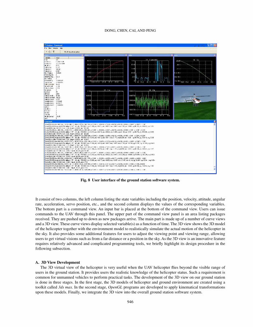
Figure 8 is a demonstration of the ground station user interface. The main window contains a number of childwindows to display the in-flight data received from the helicopter. The left hand side of the window is the state view.
945
DONG, CHEN, CAI, AND PENG
Fig. 8 User interface of the ground station software system.
It consist of two columns, the left column listing the state variables including the position, velocity, attitude, angularrate, acceleration, servo position, etc., and the second column displays the values of the corresponding variables.The bottom part is a command view. An input bar is placed at the bottom of the command view. Users can issuecommands to the UAV through this panel. The upper part of the command view panel is an area listing packagesreceived. They are pushed up to down as new packages arrive. The main part is made up of a number of curve viewsand a 3D view. These curve views display selected variable(s) as a function of time. The 3D view shows the 3D modelof the helicopter together with the environment model to realistically simulate the actual motion of the helicopter inthe sky. It also provides some additional features for users to adjust the viewing point and viewing range, allowingusers to get virtual visions such as from a far distance or a position in the sky. As the 3D view is an innovative featurerequires relatively advanced and complicated programming tools, we briefly highlight its design procedure in thefollowing subsection.
A. 3D View DevelopmentThe 3D virtual view of the helicopter is very useful when the UAV helicopter flies beyond the visible range of
users in the ground station. It provides users the realistic knowledge of the helicopter status. Such a requirement iscommon for unmanned vehicles to perform practical tasks. The development of the 3D view on our ground stationis done in three stages. In the first stage, the 3D models of helicopter and ground environment are created using atoolkit called 3ds max. In the second stage, OpenGL programs are developed to apply kinematical transformationsupon these models. Finally, we integrate the 3D view into the overall ground station software system.
946
DONG, CHEN, CAI, AND PENG
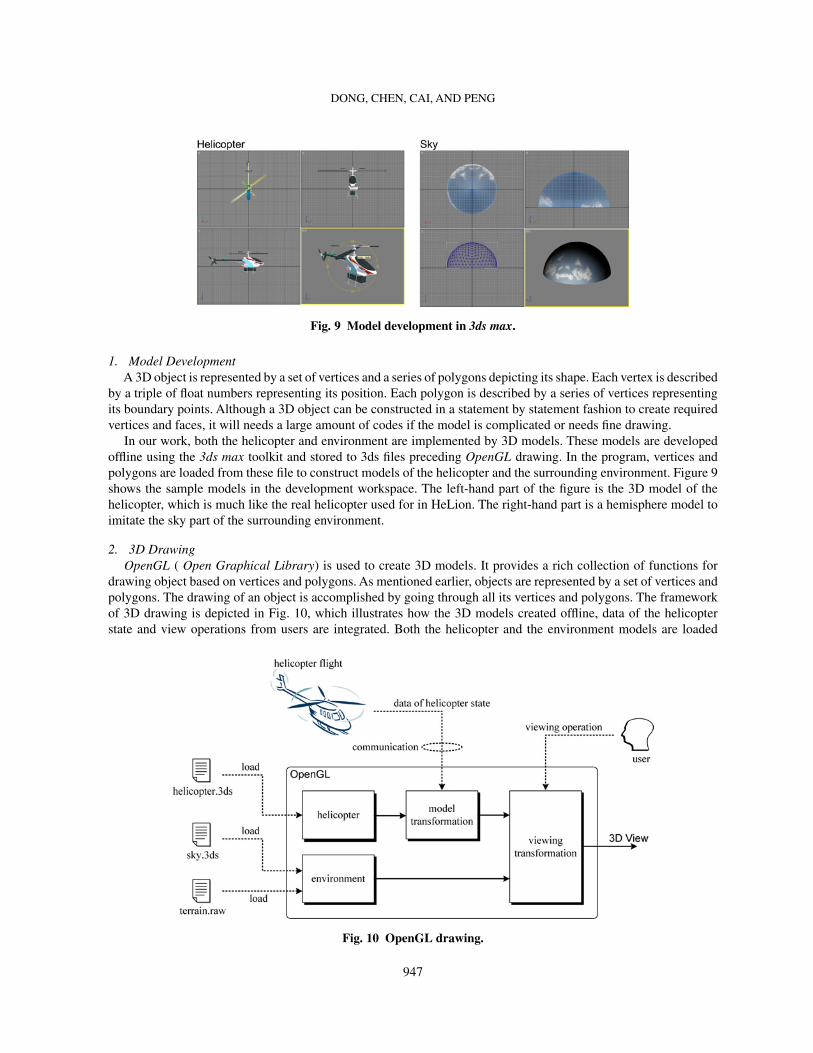
Fig. 9 Model development in 3ds max.
1. Model DevelopmentA 3D object is represented by a set of vertices and a series of polygons depicting its shape. Each vertex is described
by a triple of float numbers representing its position. Each polygon is described by a series of vertices representingits boundary points. Although a 3D object can be constructed in a statement by statement fashion to create requiredvertices and faces, it will needs a large amount of codes if the model is complicated or needs fine drawing.
In our work, both the helicopter and environment are implemented by 3D models. These models are developedoffline using the 3ds max toolkit and stored to 3ds files preceding OpenGL drawing. In the program, vertices andpolygons are loaded from these file to construct models of the helicopter and the surrounding environment. Figure 9shows the sample models in the development workspace. The left-hand part of the figure is the 3D model of thehelicopter, which is much like the real helicopter used for in HeLion. The right-hand part is a hemisphere model toimitate the sky part of the surrounding environment.
2. 3D DrawingOpenGL ( Open Graphical Library) is used to create 3D models. It provides a rich collection of functions for
drawing object based on vertices and polygons. As mentioned earlier, objects are represented by a set of vertices andpolygons. The drawing of an object is accomplished by going through all its vertices and polygons. The frameworkof 3D drawing is depicted in Fig. 10, which illustrates how the 3D models created offline, data of the helicopterstate and view operations from users are integrated. Both the helicopter and the environment models are loaded
Fig. 10 OpenGL drawing.
947
DONG, CHEN, CAI, AND PENG
from pre-created files. Real-time data required for the helicopter includes positions and attitudes transferred fromthe onboard system. View operation from users includes moving, rotating, and zooming of the virtual 3D view.
3. 3D ViewThe 3D view is lastly encapsulated in a class in C++ program. It is attached with global data, in which the in-flight
data of the UAV helicopter are stored. To dynamically simulate the motion of the helicopter, the view is updatedwith a rate of 10 Hz. In every cycle, newest values of the helicopter state are read from the global data pool and thecontent of the 3D view is repainted accordingly. The periodical update is scheduled in the program by a timer, whichis created in the initialization stage of the 3D view. In the end of each cycle, a timer message will be sent to the viewto request an update, which proceeds as in the following code.
CTDView::OnUpdate(){
double pos[3] = { _data[1], _data[2], _data[3] }; //positiondouble att[3] = { _data[7], _data[8], _data[9] }; //attitudeangle += rate*period/1000; //incremental rotor angleSetPositionAttitudeRotor(pos, att, angle); //calculate transformationGLDraw(); //redraw
}The OnUpdate function is a member of the 3D view class CTDView, which is called whenever a timer message
is captured. The front two lines get the position and attitude from the global data pool, which is updated from timeto time as the flight test progresses. The angle of the rotor is added by an incremental value every period to give aneffect of rotating. Then the member function SetPosiitonAttitudeRotor is called to assign these states to the 3D view.This function is to calculate transformation matrices and apply them to the 3d objects as described in the previoussubsection. The GLDraw member function is finally called to redraw the content of the 3D view.
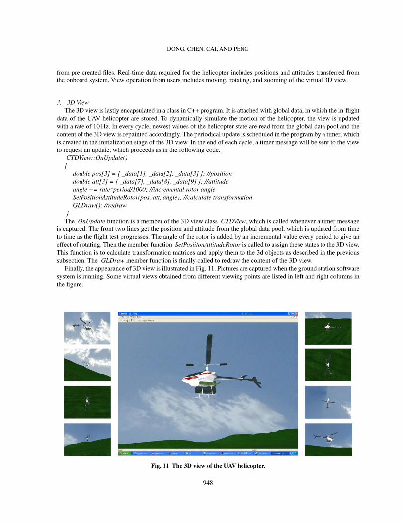
Finally, the appearance of 3D view is illustrated in Fig. 11. Pictures are captured when the ground station softwaresystem is running. Some virtual views obtained from different viewing points are listed in left and right columns inthe figure.
Fig. 11 The 3D view of the UAV helicopter.
948

DONG, CHEN, CAI, AND PENG
IV. Software Evaluation and Test ResultsIn this section, we present the evaluation and actual test results of the overall software system developed together
with some test flight results of the actual UAV helicopter.
A. Evaluation of Working Load of the Software SystemWe have performed a thorough test on the developed software system. Working load of the onboard system is
evaluated by running multiple tasks on the onboard computer. To evaluate the working load of task threads, we recordthe time used by task threads in every cycle in log file. Figure 12 shows a graph of time consumption profiles bytask threads with data being recorded from an actual test flight. We note that the communication task is scheduledto transfer data once per second due to the bandwidth limitation of the wireless communications. The data loggingthread is also operated at a slower pace as it generally requires a large amount of the CPU consumption time.
The time consumptions of all task threads are summed up in Fig. 13 as the time consumption of the main thread.The usage rate of the onboard CPU can be calculated as the ratio of the total time consumption and the length ofperiod, which is 20 ms used in the actual test. From the result shown in Fig. 13, we can determine that the lowestusage rate of the CPU is about
usagemin = τmin/T = 0.38/20 = 1.9%
Fig. 12 Time consumption by task threads.
949

DONG, CHEN, CAI, AND PENG
Fig. 13 Total time consumption of the main thread.
and the highest peak is
usagemax = τmax/T = 4.5/20 = 22.5%
where τmin and τmax stand respectively for the minimum and maximum total time consumptions by all threads in onecycle, and T is the period of the cycle. The peak of the CPU usage rate comes with the large working load of datalogging and communications, which occurs once every 50 cycles, i.e., 1 second. The average time consumption ineach cycle is about 0.52 ms. Thus, the average CPU usage rate is
usageaverage = τaverage/T = 0.52/20 = 2.6%
The low usage rate of the onboard CPU is ideal for guaranteeing the reliability of the overall software system. Tobalance working load, the communication and data logging threads have to be scheduled in a more distributive andefficient way. Some optimization technique might be utilized to yield a more efficient and optimal management ofthe system.
B. Reliability ImprovementIt is evident from the dynamic model of the UAV helicopter constructed through in-flight data collected from
actual flight tests. The UAV helicopter is an open-loop unstable system. Additional features and measures need betaken to improve the reliability of the software system and to ensure the safety of helicopter in the situation whenthe automatic control system implemented is malfunctioned. In this subsection, we present some solutions for sucha situation.
1. Onboard SimulationAlthough the control laws have to be verified by intensive simulation in MATLAB and SIMULINK offline on the
ground station or a desktop, there are still possibilities to error in the process of software implementation. Besides,faults in other parts of the onboard software system may cause serious problems in actual control of the helicopteras well. Thus, the onboard simulation is necessary for checking the validity of the software code of the control lawsimplemented. Any faults in software or in control system detected by the onboard simulation will greatly minimizepotential risks and accidences, which might happen in actual flight tests.
In our work, a software block is developed and integrated in the onboard software system to simulate the per-formance of the UAV helicopter system. It uses the dynamic model of the aircraft obtained through the modelingand identification process based on in-flight data collected from actual test flights. The function of this simulationblock acts like a virtual helicopter replacing the real UAV. Although it is also an offline simulation, its results are,however, directly sent to the ground station for verifying both the accuracy of the control system implementationand communication channels. Such an approach is proven to be very effective in detecting coding errors and faultsin the implementation of control algorithms.
950
DONG, CHEN, CAI, AND PENG
2. Emergency Handling and Black Box Data SavingThis additional safety measure is a result that we learned from a serious crash of our UAV helicopter. There are
many sources that would cause failures in the UAV control system, which includes drastic changes in environment,hardware failure, GPS disorder and problems in control system design and software implementation. A mechanismfor handling emergency situations is built in the onboard software system. At every cycle, before applying controlaction, the control task thread checks all data received from the IMU and other devices. Once any abnormality isobserved, the emergency control function is called up immediately to alert the technical people on the ground, whichmight give enough time for the ground pilot to switch the UAV system from the automatic control mode to that undermanual control.
It is also very important to keep logged data as much as possible on emergency situations as they can be used toidentify problems that cause the incidents. However, in an exceptional occasion when a crash occurs, all tasks runonboard including data logging are terminated unexpectedly. In a normal operation, the data logging file is openedat the beginning of a flight test, and is amended with in-flight data during the test, and finally closed and saved atthe end of the test. In an abnormal situation, the data logging file is likely to be corrupted, resulted in losing all data.If the process is interrupted, the whole file will be damaged. A mechanism similar to the black box in commercialaircraft is implemented to keep saving logged data even in a crash. Such a feature is illustrated in the program below:
Initialization stagedo nothing
logging stage1st time (the first 50 cycles)
open logging file in writing and appending modewrite 1st pack of data to logging fileclose logging file
2nd time (the next 50 cycles)open logging file in writing and appending modewrite 2nd pack of data to logging fileclose logging file
. . .
n-th timeopen logging file in writing and appending modewrite n-th pack of data to logging fileclose logging file
. . .
finalization stagedo nothing
As illustrated in the program above, the new feature enables the data logging process to complete data writingand saving in every 50 cycles, i.e., about 1 second. If an accident occurs, all data saved before it will remain safe andcan be used for analyzing the accident.
C. Actual Flight TestWe have performed flight tests such as hovering, forward flight, trajectory tracking and scheduled flight. We
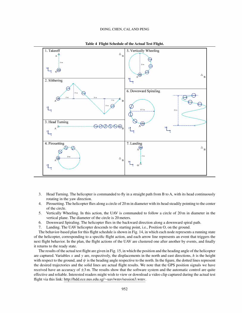
present in this subsection the test result of a scheduled flight.The schedule for demonstration is designed as in Table 4, in which the ‘x-h’ and ‘x-y’ represent the vertical plane
and horizontal plane, respectively. More specifically, the UAV helicopter is commanded to automatically take off,and then perform a series of flight actions, such as slithering, head turning, pirouetting, vertically wheeling, anddownward spiraling, and finally automatically landing to the initial position where the helicopter lifts off.
1. Takeoff. The UAV helicopter launches its engine and lifts form a ground position (marked as ‘O’) to PositionA, 15 m above the ground.
2. Slithering. The UAV moves in both forward and sideward direction, and follows a zigzag path, from PositionA to Position B. The distance between A and B is 60 m.
951
DONG, CHEN, CAI, AND PENG
Table 4 Flight Schedule of the Actual Test Flight.
3. Head Turning. The helicopter is commanded to fly in a straight path from B to A, with its head continuouslyrotating in the yaw direction.
4. Pirouetting. The helicopter flies along a circle of 20 m in diameter with its head steadily pointing to the centerof the circle.
5. Vertically Wheeling. In this action, the UAV is commanded to follow a circle of 20 m in diameter in thevertical plane. The diameter of the circle is 20 meters.
6. Downward Spiraling. The helicopter flies in the backward direction along a downward spiral path.7. Landing. The UAV helicopter descends to the starting point, i.e., Position O, on the ground.The behavior-based plan for this flight schedule is shown in Fig. 14, in which each node represents a running state
of the helicopter, corresponding to a specific flight action, and each arrow line represents an event that triggers thenext flight behavior. In the plan, the flight actions of the UAV are clustered one after another by events, and finallyit returns to the ready state.
The results of the actual test flight are given in Fig. 15, in which the position and the heading angle of the helicopterare captured. Variables x and y are, respectively, the displacements in the north and east directions, h is the heightwith respect to the ground, and ψ is the heading angle respective to the north. In the figure, the dotted lines representthe desired trajectories and the solid lines are actual flight results. We note that the GPS position signals we havereceived have an accuracy of ±3 m. The results show that the software system and the automatic control are quiteeffective and reliable. Interested readers might wish to view or download a video clip captured during the actual testflight via this link: http://hdd.ece.nus.edu.sg/∼uav/wmv/session3.wmv.
952

DONG, CHEN, CAI, AND PENG
Fig. 14 Flight Plan of the Actual Test Flight.
Fig. 15 Result of the Actual Test Flight.
953

DONG, CHEN, CAI, AND PENG
V. ConclusionA software system for an unmanned helicopter is presented in this paper. Both the onboard and ground station
systems are developed. The onboard software system has used a framework of multiple task threads to perform tasksincluding inertial measurement, data acquisition, automatic control, servo driving, communications and data logging.Software methods of synchronization are employed to manage these tasks. A scheme of time allocation is designedfor both software and hardware together with a behavior-based architecture for implementing automatic controlalgorithms. The ground station software has used a framework with two layers, i.e., data transferring in backgroundand information visualization in foreground. A unique feature of a 3D monitoring system has also been developedon the ground station for a more realistic reconstruction of the helicopter movement in the sky. The software systemhas been thoroughly tested through actual flight tests of the UAV helicopter.
The paper actually covers a range of common subjects for all unmanned vehicles such as hardware driving, taskthreads scheduling and control implementation. The software solution presented in this work can also be used toother unmanned vehicles with minimal modifications. Indeed, the development of a universal software frameworkfor all unmanned vehicles is our primarily focus in the near future.
References1Meyrowitz, A. L., Blidberg, D. R., and Michelson, R. C., “Autonomous Vehicles”, Proceedings of the IEEE, Vol. 84, No. 8,
1996, pp. 1147–1164.2Ollero, A., Lacroix, S., Merino, L., et al., “Multiple Eyes in the Skies: Architecture and Perception Issues in the COMETS
Unmanned Air Vehicles Project”, IEEE Robotics & Automation Magazine, Vol. 12, No. 2, 2005, pp. 46–57.3Wills, L., Kannan, S., Sander, S., et al., “An Open Platform for Reconfigurable Control”, IEEE Control Systems Magazine,
Vol. 21, 2001, pp. 49–64.4Kim, H. J., Shim, D. H., and Sastry, S., “A Flight Control System for Aerial Robots: Algorithms and Experiments”, Control
Engineering Practice, Vol. 11, No. 12, 2003, pp. 1389–1400.5Valavanis, K. P., Gracanin, D., Matijasevic, M., Kolluru, R., and Demetriou, G. A., “Control Architectures for Autonomous
Underwater Vehicles”, IEEE Control Systems Magazine, Vol. 17, No. 6, 1997, pp. 48–64.6Harbick, K., Montgomery, J. F., and Sukhatme, G. S., “Planar Spline Trajectory Following for an Autonomous Helicopter”,
Journal of Advanced Computational Intelligence – Computational Intelligence in Robotics and Automation, Vol. 8, No. 3, 2004,pp. 237–242.
7Corfield, S. J., Fraser, R. J. C., and Harris, C. J., “Architecture for Real-time Intelligent Control of Autonomous Vehicles”,Computing & Control Engineering Journal, Vol. 2, No. 6, 1991, pp. 254–262.
8Mataric, M. J., Sukhatme, G. S., and Østergaard, E., “Multi-robot Task Allocation in Uncertain Environments”, AutonomousRobots, Vol. 14, No. 2, 2003, pp. 255–263.
9Kottmann M., “Software for Model Helicopter Flight Control”, Technical Report, Eidgenössisches Technische HochschuleZurich, 1999.
10Jang, J. S., and Tomlin, C. J., “Design and Implementation of a Low Cost, hierarchical and Modular Avionics – Architecturefor the DragonFly UAVs”, Proceedings of AIAA Guidance, Navigation, and Control Conference, Monterey, California, 2002,pp. 4465–4477.
11Cai, G., Peng K., Chen, B. M., and Lee, T. H., “Design and Assembling of a UAV Helicopter System”, Proceedings of the5th International Conference on Control & Automation, Budapest, Hungary, 2005, pp. 697–702.
12NAV420 Series User’s Manual, Crossbow Technology Inc., 2004.13Krten, R., Getting Started with QNX Neutrino 2 – A Guide for Real-time Programmers, PARSE Software Devices, Kanata
Ontario, 1999.14QNX Momentics (v6.3 SP2) Documentation, QNX Software Systems Corporation.15Dong M. and Sun Z., “A Behavior-based Architecture for Unmanned Aerial Vehicles”, Proceedings of International
Symposium on Intelligent Control. Taipei, Taiwan, 2004, pp. 149–155.16Mali, A. D., “On the Behavior-based Architectures of Autonomous Agency”, IEEE Transactions on Systems, Man and
Cybernetics, Vol. 32, No. 3, 2002, pp. 231–242.17Scheutz, M., and Andronache, V., “Architectural Mechanisms for Dynamic Changes of Behavior Selection Strategies in
Behavior-based Systems”, IEEE Transactions on Systems, Man and Cybernetics – Part B: Cybernetics, Vol. 34, No. 6, 2004, pp.2377–2395.
18Fagg, A. H., Lewis, M. A., Montgomery, J. F., and Bekey, G. A., “The USC Autonomous Flying Vehicle – an Experimentin Real-time Behavior-based Control”, Proceedings of the 1993 IEEE/RSJ International Conference on Intelligent Robots andSystems, Yokohama, Japan, 1993, pp. 1173-1180.
954
DONG, CHEN, CAI, AND PENG
19Mettler, B., Tischler, M. B., and Kanade, T., “System Identification Modeling of a Small-scale Unmanned Helicopter”,Journal of the American Helicopter Society, Vol. 47, No. 1, 2002, pp. 50–63.
20Mettler, B., Tischler, M. B., and Messner W., “Attitude Control Optimization for a Small-scale Unmanned Helicopter”,Proceedings of AIAA Guidance, Navigation and Control Conference, Denver, Colorado, 2000.
21Cai, G., Chen, B. M., Peng K., Dong, M., and Lee, T. H., “Modeling and Control System Design for a UAV Helicopter”,Proceedings of the 14th Mediterranean Conference on Control Automation, Ancona, Italy, 2006.
22Chen, B. M., Lee, T. H., Peng, K., and Venkataramanan, V., “Composite Nonlinear Feedback Control for Linear SystemsWith Input Saturation: Theory and an Application”, IEEE Transaction on Automatic Control, Vol. 48, No. 3, 2003, pp. 427–439.
23He, Y., Chen, B. M., and Wu, C., “Composite Nonlinear Control with State and Measurement Feedback for GeneralMultivariable Systems with Input Saturation”, Systems & Control Letters, Vol. 54, No. 5, 2005, pp. 455–469.
24Kruglinski, D. J., Inside Visual C++ (4th edition), Microsoft Press, Redmond, Washington, 1995.
Ella AtkinsAssociate Editor
955