Embed Size (px)
Citation preview

Development of a Method for Detecting Debris
at the Entrance to Submerged Orifices
by Alvin L. Jensen
and Clifford W. Long
December 1983
DEVELOPMENT OF A METHOD FOR DETECTING DEBRIS
AT THE ENTRANCE TO SUBMERGED ORIFICES
by Alvin L. Jensen
and Clifford W. Long
Financed by U.S. Army Corps of Engineers (Contract DACW57-83-F-0369)
and
Coastal Zone and Estuarine Studies Division Northwest and Alaska Fisheries Center
National Marine Fisheries Service National Oceanic and Atmospheric Administration
2725 Montlake Boulevard East Seattle, Washington 98112
December 1983

TABLE OF CONTENTS
Page
INTRODUCTION. 1
DESCRIPTION OF TECHNIQUES · • • • 4
Paired Aneroid Sensors. • 4
Circular Flange Load Cell . • 6
LABORATORY STUDY. • 6
Methods • • 9
Results and Discussion. • 9
Paired Aneroid SensoTs. • • • 9
Circular Flange Load Cell • • • • • • 11
FIELD TRIAL • • • • • • • • • • • • .11
Methods • • • • • • • • • .11
Results and Discussion. • • • • • • • • • • • • • 12
CONCLUSIONS AND RECOMMENDATIONS • • • • 15
LITERATURE CITED. • • • • • • • 16

INTRODUCTION
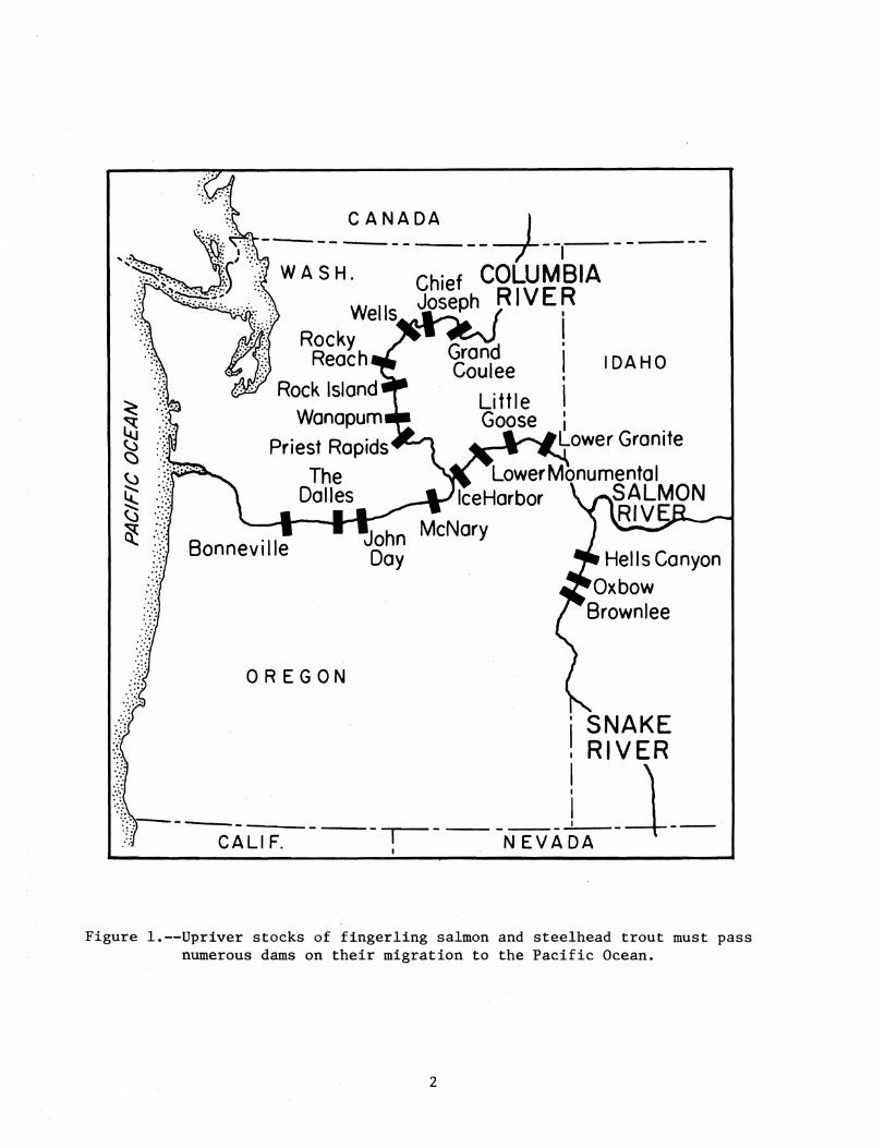
Fingerling salmon and trout migrating down the Snake and Columbia
River systems must pass a number of low-head dams (Figure 1). A high rate
of mortality may occur as the fish pass through the turbines and the large
populations of predators in the tailraces (Long et al. 1968). The
discovery that the migrating fingerlings naturally concentrate in turbine
intake gatewells has led to efforts to utilize this tendency as a means for
increasing fingerling survival (Long 1968; Long and Krcma 1969). As a
consequence, traveling screens are now in use to enhance the numbers of
fish entering the intake gatewells where they are permitted to exit through
an orifice into a fish bypass (Figure 2). A collection system at the
terminal end of the bypass may be used to concentrate the fish for trucking
or barging around the remaining dams or the fish may simply be released
into the river downstream from the dam (Matthews et ale 1977).
The orifices that permit fish to pass from the intake gatewells to the
bypass sometimes collect debris across their entrance that can injure fish.
Although turbine intakes are protected by trash racks which exclude large
debris, much small debris enters the intakes and the intake gatewells.
Sticks frequently hang up at the entrances to the gatewell orifices and
form a base upon which other materials may accumulate. When fingerlings
are trapped by the velocity of the water flowing into an orifice, they
cannot avoid contact with the debris and are often descaled or otherwise
injured.
1
'''':S'';..''i~") ROCk;ells Joseph
R h eac
'., ':. C ANA DA I ~ \\1t '<'. ------- ---r-"~(:/ WASH. Chief COLUM1SIA
R I V E r Grand I IDAHOCoulee
I
~ I ~ (.j ()
(,.)
~ ~ "-J
~
SNAKE I RIVER
-r---------11I
CALI F. - I NEVA DA - -
..... :::.
Wanapum
Priest Rapids
The Dalles
Little Goose I
__--.---Lower Granite
'.'
):: Bonneville , .' Hells Canyon
Oxbow Brownlee
OREGON
Figure l.--Upriver stocks of fingerling salmon and steelhead trout must pass numerous dams on their migration to the Pacific Ocean.
2

Ice and trash sluiceway
TURBINE INTAKE
Forebay water level
Trash rack -----'1:'\1
Figure 2.-- Transverse cross section through typical turbine intake of first powerhouse at Bonneville Dam showing location of submerged orifice and debris detector in gatewell.
3

At most dams, such as Bonneville and John Day, no simple method exists
for determining when the orifices begin accumulating debris because both
the entrances and exits of the orifices are submerged and cannot be seen.
Divers must often be used to inspect the orifices and remove accumulated
debris. This method is very expensive and does not provide for timely
action.
To develop a simple, effective means of detecting debris at orifice
entrances, the National Marine Fisheries Service, under contract to the
u.S. Army Corps of Engineers, selected two techniques for detailed testing:
paired aneroid sensors and circular flange load cells. The objectives were
to test both techniques under controlled hydraulic conditions (laboratory
study) to verify the general feasibility, and then test one or both
techniques under actual field conditions (field trial).
DESCRIPTION OF TECHNIQUES
Both techniques were able to detect changes in pressure at the
orifice entrance due to the presence of debris. The major problem was to
distinguish pressure changes due to the presence of debris from pressure
changes due to other factors, e.g., changes in water pressure due to
fluctuations in orifice submergence and changes in pressure due to
fluctuations in water veloci ty caused by changes in the hydraulic head on
the orifice.
Paired Aneroid Sensors
Figure 3 shows the aneroid sensor rings as assembled for testing. A
plastic orifice ring was grooved to accept two air-filled rings of 5/16
4

A
B
Figure 3.--Two views of paired aneroid sensor rings partly embedded in ring of plastic.
5

inch diameter surgical tubing. Each ring was connected via tubing to a
differential pressure gauge. In principle, the pressure due to submergence
or water velocity would affect both sensors the same, and only pressure
differences caused by debris in contact with the front tube would be
transmitted to the readout.
Circular Flange Load Cell
Figure 4 shows the design of the load cell and Figure 5 is the
complete assembly. Strain gauges were mounted on a carefully machined area
of a metal flange so that any deflection of the flange outputs an
electrical signal.
We anticipated that deflection (signal output) caused by changes in
water velocity due to changes in hydraulic head would occur slowly, whereas
deflection due to impingement of debris would occur rapidly. These
differences then, would be used to detect the presence of debris. In
addition, we hoped that the baseline signal (when no debris is present)
would always have a relatively narrow range for any given hydraulic head
and submergence. The more discrete this baseline signal, the more certain
the operator could be in determining that, after removal of the debris, all
the debris was indeed removed.
LABORATORY STUDY
The objectives of the laboratory study were to examine the sensitivity
of each technique for detecting debris; to verify that the presence of
debris could be consistently detected; and to discover, if possible, any
problems that might affect long-range reliability.
6

14.88 outer diameter
\45° typical
\ 11.50 inner diameter
17/64 inch diameter hole in 4 positions (CBore 0.38 inch diameter x 0.32 inch deep hole in far sides)
, ...---- Strain guage: 350 n
16 positions Outer-tension Inner-compression
0.62
~0.25 T
LOAD
Capacity: 100 pounds (uniform load) Output: 2.00 mVIV nominal Terminal resistance: 350 n Temperature range: 32° -100" F Combined accuracy: Y:z of 1° full scale
Figure 4.--Design of circular flange load cell.
7

A
B
Figure 5.--A = view of existing circular flange insert forming entrance to submerged orifice. B = circular flange load cell was constructed to replace the circular flange insert.
8

Methods
The study was conducted in an oval flume where water was pumped through
a bank of jets to obtain the desired velocity (Figure 6). A panel
containing a 12-inch diameter orifice was inserted in the path of the flow
to simulate conditions as they exist at orifices in gatewells. Hydraulic
head and submergence, however, were limited to 1.5 and 4.0 feet,
respectively.
For the sensitivity tests, we employed a 1/4-inch diameter dowel of
sufficient length to span the 12-inch diameter orifice. We judged that a
single stick of this size probably would not present a hazard to the
fingerling salmon transiting the orifice, but could be considered the
minimum debris that could present a problem because a single stick of
smaller diameter most likely would be broken and carried through the
orifice by the velocity of the flowing water.
Results and Discussion
Paired Aneroid Sensors
Sensitivity tests employing the 1/4-inch diameter dowel were conducted
at a hydraulic head of approximately 1 foot. Although the rings of
surgical tubing suffered from a lack of stability, particularly at higher
water velocities, the addition of the 1/4-inch diameter dowel produced a
significant change in the mean differential pressure at all velocities.
The inherent instability of this method at the relatively low
velocities available in the flume suggested that, under the higher
velocities which could occur in the field, fluctuations in pressure might
be severe enough to mask the presence of small debris.
9

1-41------------33 feet------------+l·1
Wate, int,:ction jets l ~ FLOW
17 feet
To pumps ~---
~ -))
Hydraulic head
Submergence 7 feet
" - ~FLOW~
Debris detector"""'-' Submerged orifice Panel
ELEVATION
Figure 6.--Oval flume in which laboratory study was conducted.
PLAN VIEW
Plexiglass / test section
10

We also found that the resiliency of the surgical tubing changed with
the duration of submergence, which in turn resulted in a difference in the
response to pressure pulses. Apparently, the surgical tubing was slowly
absorbing water.
These problems no doubt can be solved; however, continued pursuit of
this technique ·was considered to be beyond the scope of the present
contract.
Circular Flange Load Cell
The circular flange load cell was tested at hydraulic heads of 1 to 3
feet. Under all velocities, the signal produced by the load cell was
reproducible, and the addition of the 1/4-inch diameter dowel produced a
clear-cut signal. The results clearly showed that this method warranted
further study. We therefore decided to test the circular flange load cell
under actual conditions.
FIELD TRIAL
A single trial of the circular flange load cell was made in Gatewell
3B in the first powerhouse at Bonneville Dam. The objective was to
determine if the load cell would be adversely affected by field condit ions
and to verify that it would work as it did in laboratory tests.
Methods
The circular flange load cell assembly was mounted at the orifice
intake by means of an adapter that replaced the existing orifice plate
(Figure 5). This provided a mount that was essentially flush with the face
11

of the gatewell's inner wall, thereby eliminating any projections that
could interfere with normal maintenance operations. Submergence of the
orifice was approximately 8 feet, and the hydraulic head was approximately
2 feet.
The signal from the load cell was fed through signal conditioning
circuitry to a Motorola-based GIMIX Model 09 micro-computer!! with a
Televideo Model 925 terminal. The computer was programmed in Forth
language to allow various combinations of running and exponential averages
to be used in signal conditioning. The computer was interfaced to the load
sensing ring through a Tri-Coastal signal-condit ioni ng amplifier and a
triple integrating analog-to-digi tal converter. The output was converted
back to an analog signal for input to a strip chart recorder. This system
permitted adjustments to be made quickly and easily so that suitable output
signals could be obtained.
Results and Discussion
The tests indicated that the load-cell debris detector provided a
means for detecting debris which impinged upon gatewell orifices. Figure 7
is a sample of the output of the conditioned signal. Analysis of the test
data showed that the most serious concern with the load-cell detector was
the necessity to re-establish the true base line each time debris was
removed.
We found that the baseline signal (without the presence of debris) for
the submergence and hydraulic head tested varied significantly over time,
YReference to trade name does not imply endorsement by the National Marine Fisheries Service, NOAA.
12

--------------T-------~----------------_.-----------10
Removal Debris ----1--- No debris -- 9-- No debris __.L. of debris -.----- in place
--------------r-----~r-----------------r_----------8
------------+-----~~~~~~r_~~----------7
-------------~~----------------------~~----------6
------------------------------~----------------------4
----------------------------------------------------3
------------------------------------------------------2
-----------------------------------------------------1
----------~----~------~--------------------------o
~ TIM E
Figure 7.--Trace of signal output from circular flange load cell with and without 1/4-inch diameter dowel in place.
13
thus producing a wide range of output signals. It may be possible for
example, that after the removal of debris, subsequent baseline signals in
the high part of the normal range might actually be due to a combination of
a true baseline signal in the low part of the range plus a small amount of
debris that failed to be removed. Under certain ,
condi tions of flow and
submergence, it may be possible to incorrectly assume that complete debris
removal was achieved.
The possibility of utilizing a paired-sensor system as a means to
avoid the potential baseline problems was considered and appears to be
pract ical. Sufficient information was collected during testing to
establish the parameters for construction of a suitable paired-sensor
system. In essence, a detector assembly would contain two separate rings
{matched sensor arrays)--an outer ring and an inner ring. The inner ring
would not be contacted by debris but would be affected by changes in flow,
temperature, etc. and provide baseline compensation. The signal from each
array would be fed to an amplifier/filter which would permit initial
adjustment of zero and gain. The condi tioned signal from each of the
arrays would be fed to a comparator, and any signal difference would be
used as output to an alarm or signal/control system. Since both arrays
would be subjected to the same influences except for the debris itself, any
changes in baseline conditions would be compensated for automatically, and
the reference point would remain fixed. The electronics required for
signal conditioning would be simpler, less subject to outside influences,
and would require less intervention and monitoring by operating personnel.
14

CONCLUSIONS AND RECOMMENDATIONS
The testing indicated the capability of the load-cell to detect debris
under operational conditions. We feel that the sensitivity and durability
of the sensor system are adequate for the application. By using a paired
sensor system, the potential problem of base-line instability can be
circumvented and operation of the system can be simplified. Such a system
will lend itself readily to automated control of debris removal.
Based upon the information obtained thus far, we recommend the
construction and installation of three or four paired-sensor array load
cells in the orifices of operating turbine intake gatewells. These units
would be operated as a prototype system for testing and evaluation.
Various alarm/control systems could be tested at the same time to establish
the level of automation desired.
Anticipated capital costs for the proposed test system would be
approximately $4,000 each for the double-ring load cells and approximately
. $700 each for the associated electronics. These costs would be reduced in
production quantities.
15

LITERATURE CITED
Long, Clifford W. 1968. Diel movement and vertical distribution of juvenile anadromous
fish in turbine intakes. Fish. Bull., 66:3.
Long, Clifford W., Richard F. Krcma, and Frank J. Ossiander. 1968. Research on fingerling mortality in kaplan turbines - 1969.
Internal Report, Bureau of Commercial Fisheries. 2725 Montlake Boulevard East, Seattle, Washington 98112.
Long, Clifford W., and Richard F. Krcma. 1969. Research on a system for bypassing juvenile salmon and trout
around low-head dams. Comm. Fish. Rev. June 1969.
Matthews, Gene M., George A. Swan, and Jim Ross Smith. 1977. Improved bypass and collection system for protection of
juvenile salmon and steelhead trout at Lower Granite Dam. Mar. Fish. Rev. Paper 1,265. 39:7.
16