Embed Size (px)
Citation preview
Development of a kW Prototype Coal-based Fuel Cell
DE-FG36-06GO86055
Steven S. C. ChuangDepartment of Chemical and Biomolecular Engineering
The University of AkronAkron, OH 44325-3906 USA
Acknowledgement: US Department of Energy, Ohio Coal Development Office, Ohio Board of Regents; Univ. of Akron Students: J. Fisher, D. Miller, F. Guzman, R. Singh, and Z. Yu,
FCP 41
This presentation does not contain any proprietary or confidential information
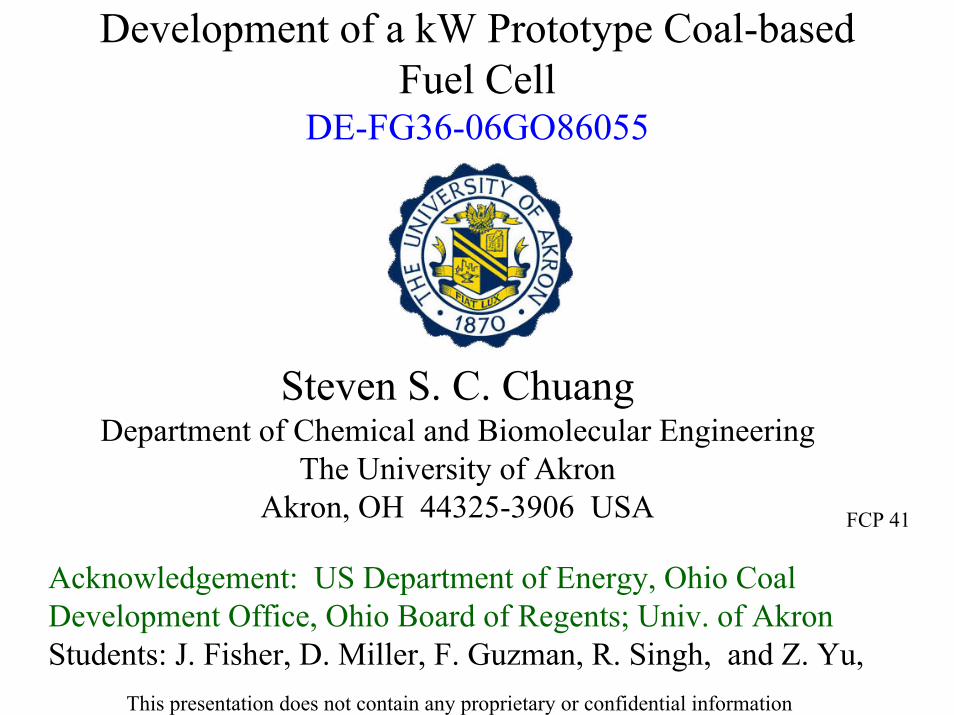
Relationship between fuel processing and fuel cells
Rita Bajura, CCPI-Round 2, Planning Workshop, Aug. 23, 2003_
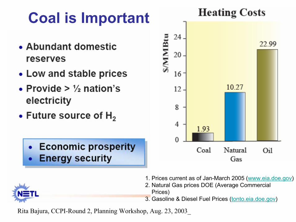
Coal is Important
1. Prices current as of Jan-March 2005 (www.eia.doe.gov)2. Natural Gas prices DOE (Average Commercial
Prices)3. Gasoline & Diesel Fuel Prices (tonto.eia.doe.gov)

Coal Fuel Cell
Source: The University of Akron
Disposal
Coal-based Fuel Cell
Coal Gasification + Cleaning + Syngas Fuel Cell and Turbine/ Generator
J. Johnson, Volume 82, Number 08, Chemical & Engineering News, February 23, 2004
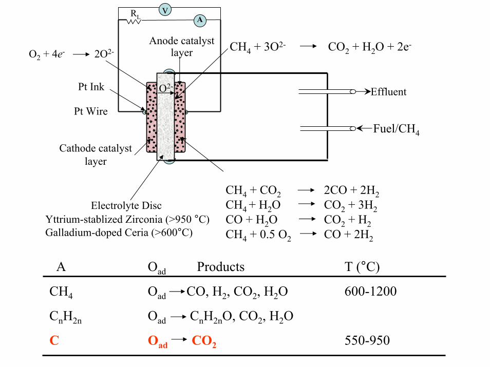
Pt Ink
Fuel/CH4
Effluent
CH4 + CO2 2CO + 2H2CH4 + H2O CO2 + 3H2CO + H2O CO2 + H2CH4 + 0.5 O2 CO + 2H2
O2-
CH4 + 3O2- CO2 + H2O + 2e-
Electrolyte Disc
Cathode catalyst layer
Anode catalyst layer
Pt Wire
Yttrium-stablized Zirconia (>950 °C)Galladium-doped Ceria (>600°C)
O2 + 4e- 2O2-
A Oad Products T (°C)
CH4 Oad CO, H2, CO2, H2O 600-1200
CnH2n Oad CnH2nO, CO2, H2O
C Oad CO2 550-950
vA
RL
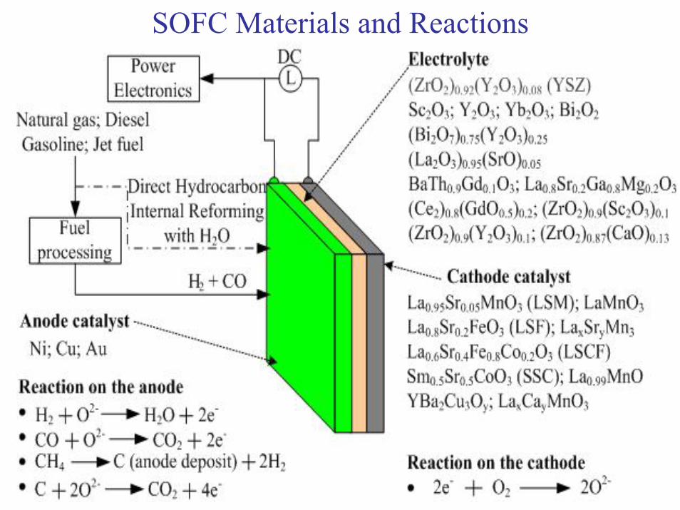
SOFC Materials and Reactions
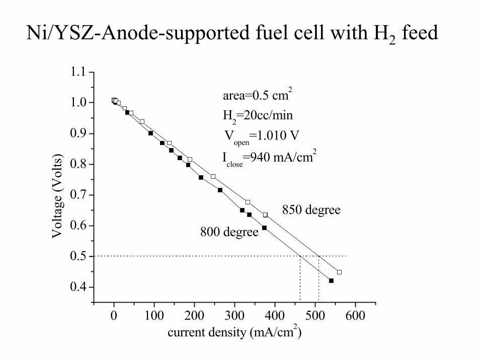
Ni/YSZ-Anode-supported fuel cell with H2 feed
0 100 200 300 400 500 600
0.4
0.5
0.6
0.7
0.8
0.9
1.0
1.1
800 degreeVol
tage
(Vol
ts)
current density (mA/cm2)
H2=20cc/minVopen=1.010 VIclose=940 mA/cm2
850 degree
area=0.5 cm2

0 100 200 300 400 500 6000.0
0.2
0.4
0.6
0.8
1.0
1.2
0
50
100
150
200
250
Current Density (mA/cm2)
volta
ge (V
)
Pow
er (m
W/c
m2 )
H2 after coking
CH4
H2
20 μm Ni-based anode/600 μm YSZ disk/50 μm LSM/YSZ cathode
Cathode area=0.5 cm2
Temperature=850 oC
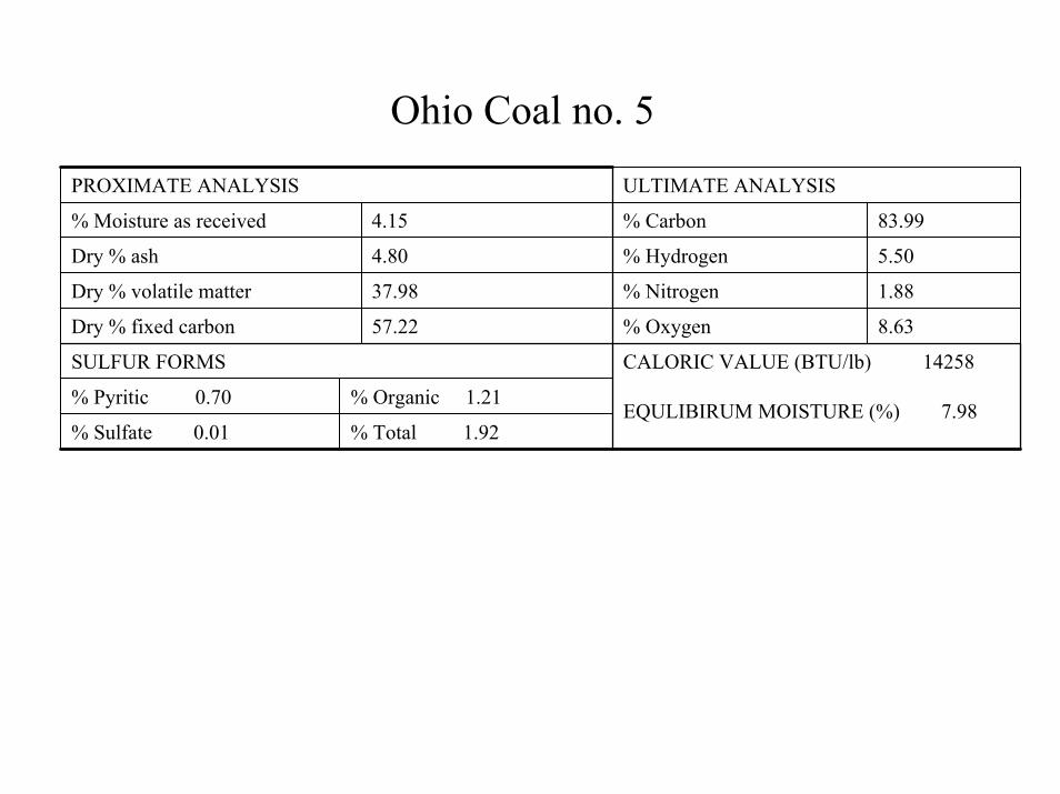
PROXIMATE ANALYSIS ULTIMATE ANALYSIS
% Moisture as received 4.15 % Carbon 83.99
Dry % ash 4.80 % Hydrogen 5.50
Dry % volatile matter 37.98 % Nitrogen 1.88
Dry % fixed carbon 57.22 % Oxygen 8.63
SULFUR FORMS
% Pyritic 0.70 % Organic 1.21
% Sulfate 0.01 % Total 1.92
CALORIC VALUE (BTU/lb) 14258
EQULIBIRUM MOISTURE (%) 7.98
Ohio Coal no. 5
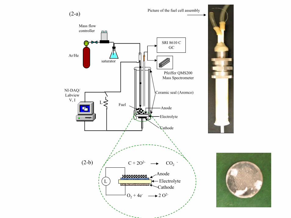
LCathode
Anode
O2 + 4e- 2 O2-
C + 2O2- CO2-
Electrolyte
Pfeiffer QMS200Mass Spectrometer
Picture of the fuel cell assembly
Anode
Cathode
Electrolyte
Ceramic seal (Aremco)
Ar/Hesaturator
Mass flow controller
NI-DAQ/Labview
V, I
SRI 8610 CGC
FuelL
(2-a)
(2-b)
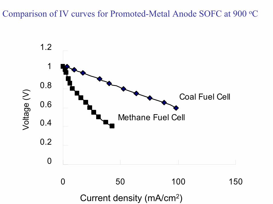
0
0.2
0.4
0.6
0.8
1
1.2
0 50 100 150
Volta
ge (V
)
Coal Fuel Cell
Methane Fuel Cell
Current density (mA/cm2)
Comparison of IV curves for Promoted-Metal Anode SOFC at 900 oC
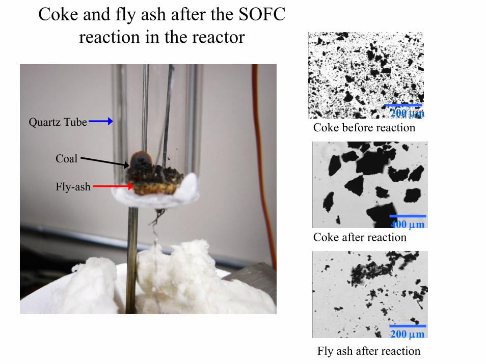
200 μm
400 μm
200 μm
Coke before reaction
Coke after reaction
Fly ash after reaction
Coke and fly ash after the SOFC reaction in the reactor
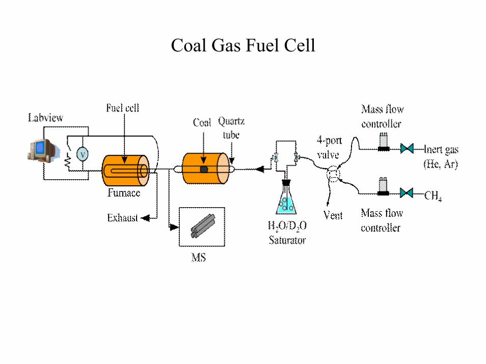
Coal Gas Fuel Cell

Temperature(degC)
H2 (m/e = 2)
HD (m/e = 3)
C (m/e = 12)
CH4 (m/e = 16)
CO ( m/e = 28)
CO2 (m/e = 44)700
(60 min)27 800
(60 min)900
(60 min)950
(60 min)
AB C D E F G H I
MS
Inte
nsity
(a.u
.)
2e-10
SO2 ( m/e = 64)
MS Profiles during Gasification of Ohio Coal # 5
0
0.2
0.4
0.6
0.8
1
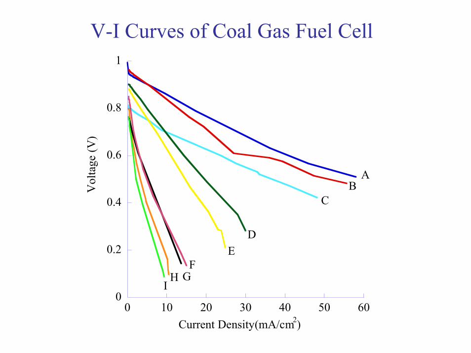
0 10 20 30 40 50 60
Vol
tage
(V)
Current Density(mA/cm2)
AB
C
DE
FGH
I
V-I Curves of Coal Gas Fuel Cell
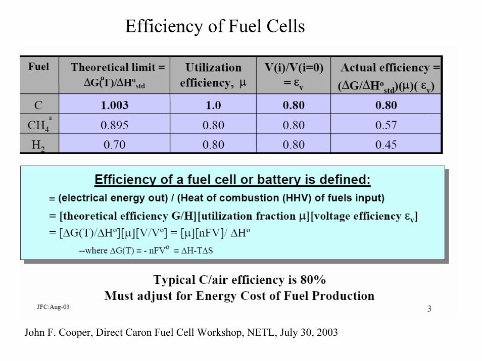
Efficiency of Fuel Cells
John F. Cooper, Direct Caron Fuel Cell Workshop, NETL, July 30, 2003
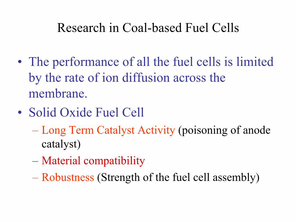
Research in Coal-based Fuel Cells
• The performance of all the fuel cells is limited by the rate of ion diffusion across the membrane.
• Solid Oxide Fuel Cell– Long Term Catalyst Activity (poisoning of anode
catalyst)– Material compatibility – Robustness (Strength of the fuel cell assembly)
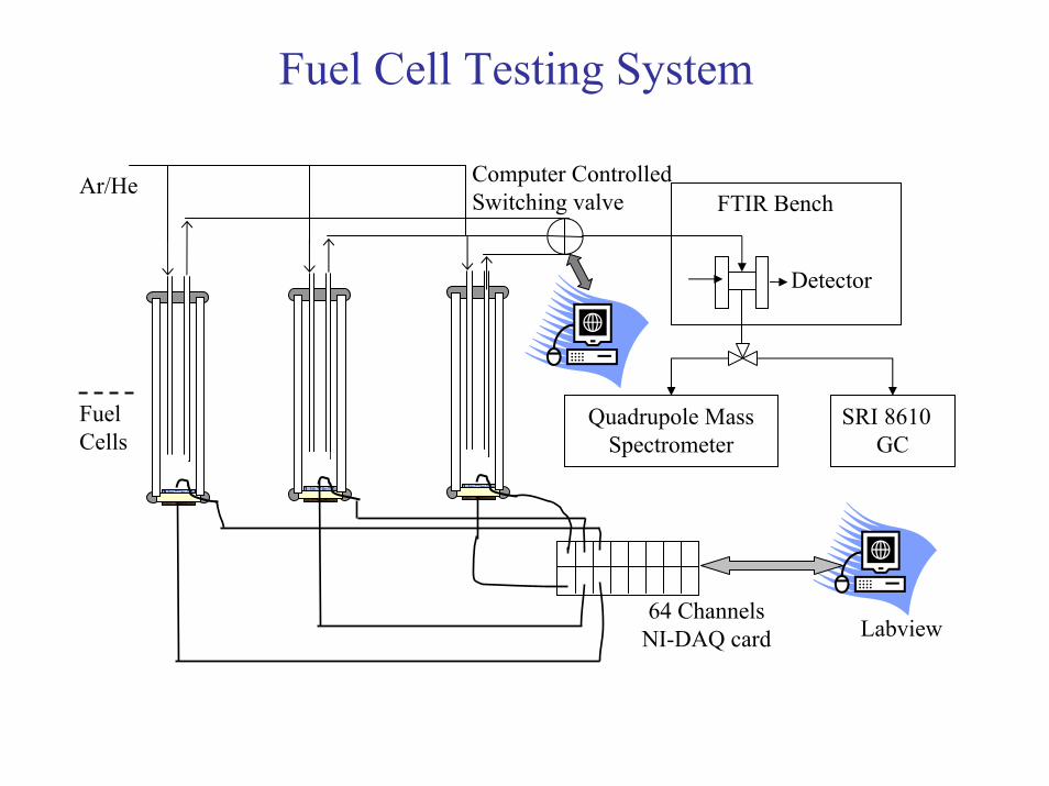
Ar/HeFTIR Bench
Detector
Computer Controlled Switching valve
64 ChannelsNI-DAQ card Labview
Quadrupole Mass Spectrometer
SRI 8610GC
Fuel Cells
Fuel Cell Testing System
Summary • Power density: Petcoke> Coal > Coal gas > CH4
• Fly ash produced from coal at 950 0C did not foul the anode catalyst surface.
• Future Tasks:– Task 1: Improvement of the anode catalyst structure and
the interface between electrode and membrane. – Task 2: Refinement of the techniques for fabrication of the
fuel cell assembly – Task 3: Selection and testing of interconnect materials for
the coal-based fuel cell. – Task 4: Investigation of the design factors for the coal
injection and flyash removal systems. – Task 5: Design and fabrication of a 5 kW prototype coal
fuel cell.


![Cofiring Biomass and Coal Agriculture for Fossil Fuel ... · per kilowatt [kW]-hour) for wood pellet combustion were less than 10 percent of those for two coal types used in Canada](https://img.pdfslide.us/doc/110x75/5edf906bad6a402d666ae63e/cofiring-biomass-and-coal-agriculture-for-fossil-fuel-per-kilowatt-kw-hour.jpg)