Embed Size (px)
Citation preview

DEVELOPMENT OF A GENERIC WIND FARM
SCADA SYSTEM
ETSU W/45/00526/REP
DTI/Pub URN 01/1124
ContractorGarrad Hassan and Partners
Prepared by G Smith
The work described in this report was carried out under contract as part of the DTI Sustainable Energy Programmes. The views and judgements expressed in this report are those of the contractor and do not necessarily reflect those of the DTI.
First published 2001 © Crown copyright 2001

Executive Summary
The aim of the project is to develop a “Generic Wind Farm Supervisory Control and Data Acquisition (SCADA) System” for the wind energy industry. A SCADA is a computer-based system that allows local and remote control of basic wind turbine functions and collects data from the wind farm that can be used to analyse and report on the operational performance. As wind farm size, complexity and remoteness of location increase an industry standard SCADA is vitally important to allow effective operation, monitoring, control and reporting.
Turbine manufacturers offer a number of existing systems but these do not always fully meet the needs of wind farm operators and owners. Operators and owners who are involved with more than one turbine supplier end up with a number of incompatible systems. This causes operational difficulties and makes it hard to compare performance data from different turbines.
This project aims to address these issues and develop a system that will communicate with all turbine types and calculate and store performance data in a consistent way.
A unit called a “Remote Interface Unit” has been developed to communicate directly with the turbine controllers and provide a standard interface to the rest of the SCADA system. It will also have local storage and processing to make the system less dependent on the reliability of the site communications network.
The site communications network is based on an industry-standard protocol (Modbus). The system has been designed so that it can operate on the simplest of networks but will also be able to make use of faster TCP/IP networks when these become cost-effective for wind farm applications.
The system runs on Windows NT and is built from software components using standard, open interfaces (e.g. OPC, ODBC, and Web technology). All user access is through standard Web browsers, allowing multi-user access and simple remote access without any special software.
The system has extensive reporting facilities that allow users to build customised reports from standard, verified options. Reports can be created on demand or can be scheduled and delivered by email. This includes the facility for automatically generating daily, weekly, monthly and annual reports.
Extensive laboratory tests have been carried out and pilot tests have taken place on a commercial wind farm in the UK.
The completed system will be available as a commercial product.
Keywords: SCADA, Wind farm, CMS, CMCS
i

CONTENTS
Page
1. BACKGROUND 1
2. DESIGN CONCEPT AND PHILOSOPHY 22.1 System Overview and Design Method 22.2 Requirements Specification 22.3 System Components 3
3. DEVELOPMENT PROCESS 43.1 System Design - Top Level 4
3.1.1 Turbine controller interface 43.1.2 Site network - Physical Layer 53.1.3 Site network - Protocol Layer 83.1.4 Selection of SCADA package 93.1.5 Server Design 103.1.6 Database Selection 113.1.7 Remote Access Options 123.1.8 GUI 12
3.2 System Design - Components 133.2.1 System Overview 133.2.2 Site Configuration Database 143.2.3 Data Database 143.2.4 Modbus Interface 153.2.5 Turbine States, Commands and Availability Definitions 153.2.6 Security 15
4. TESTING 174.1 Office Testing 174.2 Site Tests 18
5. SPECIFICATION 19
6. FURTHER WORK 19
7. EXPLOITATION AND DISSEMINATION OF RESULTS 207.1 Market Study 207.2 Value Analysis Study 217.3 Protection of Results 217.4 Exploitation Strategy 22
8. REFERENCES 23
9. GLOSSARY 24
11

Figure 1
Figure 2
APPENDIX A
APPENDIX B
General Arrangement of Generic Wind Farm SCADA System
Generic Wind Farm SCADA Components
AVAILABILITY DEFINITION
SYSTEM SPECIFICATION
iii
1. BACKGROUND
A number of existing wind farm SCADA systems are offered by turbine manufacturers but these do not fully meet the needs of wind farm operators and owners.
Operators and owners who are involved with more than one turbine supplier end up with a number of incompatible systems. This causes operational difficulties and makes it hard to compare performance data from different turbines.
The project aims to address these issues and develop a system that will communicate with all turbine types and calculate and store performance data in a consistent way.
At present there is only one well-known major supplier of a SCADA system that is independent of the wind turbine and of the wind turbine controller. Whilst this system does overcome some of the shortcomings of systems available from turbine manufacturers it has been on the market for some time and although well developed has some limitations. It is inflexible so any changes to the system are expensive to implement. It is known that users have become increasingly frustrated with not being able to change or customise systems to their own requirements.
A small number of other system developers are working on specific windfarm SCADA but so far their systems are not developed for use with any turbine or for the wider marketplace.
Some major developers/operators are known to be developing their own systems either in house or with assistance from software developers.
The project was carried out by Garrad Hassan, together with 3 project partners
• Bonus Energy A/S• Italian Vento Power Corporation (IVPC)• National Wind Power (NWP)
1

2. DESIGN CONCEPT AND PHILOSOPHY
2.1 System Overview and Design Method
Figure 1 shows a general arrangement for the generic wind farm SCADA system.
The SCADA system has been developed using the following approach:
1. Specification of system to achieve functional requirements of users2. Design and testing of software3. Design and testing of hardware4. System Testing
• Initial tests with simulations in the workshop• Initial field tests with a single wind turbine• Final testing with a wind farm
2.2 Requirements Specification
Discussions were held with the project partners and other potential users of the SCADA system to identify what functionality the system should provide and what the shortcomings of existing products are.
In addition to the project partners, GH have held discussions with the following organisations:
1. Midtkraft. Danish utility. Operations include Tuno Knob offshore wind farm.
2. Vestas. Danish wind turbine manufacturer.3. NEG Micon (DanControl). Danish wind turbine and SCADA manufacturer.
Feedback from these meetings has been very positive.
GH has additionally met with UMIST who were co-ordinators of a Joule project, “Lightning Protection of Wind Turbines” [3], to discuss lightning protection issues of wind farm SCADA systems.
GH has held discussions with DEWI on the results from the Joule project “Measuring Footprints of Wind Turbine Fatigue Loads Using Monitoring Methods” [4]. The system specification will allow for equipment used in this project to be connected to the SCADA system and for data retrieval to be carried out by the system.
The specification allows for data suitable for MEASNET measurements to be collected and retrieved by the system.
Based on these discussions and on experience from use of wind farm SCADA systems a Requirements Specification [2] has been written by GH and accepted by the project partners as the deliverable of Task 1 [1]. This covers requirements for the whole system, both hardware and software.
2

2.3 System Components
The technical options for the SCADA system have been examined in some detail in the context of the Requirements Specification.
For the purposes of system design, the generic wind farm SCADA system is divided up into the following components
1. Turbine Controller Interface
2. Site Network• Physical Layer• Protocol
3. SCADA Server• SCADA Service• Database• User Interface• Querying and Reporting Process
From a technical point of view, the site network and the method of interfacing to the individual turbines were identified as being key to the success of the SCADA system.
It has been assumed that the SCADA system will connect to turbine controllers without any changes being made to the turbine controllers. A mechanism is therefore needed to allow improved performance and additional functionality to that provided by existing wind farm SCADA systems without requiring changes to be made to the turbine controllers. This is discussed further in the following sections.
3

3. DEVELOPMENT PROCESS
3.1 System Design - Top Level
3.1.1 Turbine controller interface
The SCADA system will be required to communicate with different types of turbine. To be able to achieve this a common interface to the turbine is required. This could be implemented at the central computer or at the turbines.
It has been decided that the best approach for the system is to provide for a common interface at the turbines. This will be achieved using electronic equipment, called a Remote Interface Unit (RIU), installed at each turbine. This unit was identified as a Turbine Interface Unit in [1] but has been renamed, as it will potentially also be used to interface to meteorological masts and substations as well as turbines.
The RIU will communicate directly with the turbine controller and provide a common interface to the site network and central computer. This approach gives a number of advantages:
1. Turbine controllers are designed to interface to specific networks and will not support the option of peer-to-peer networks. Using a RIU allows the site network to be designed independently of the turbine controllers.
2. The RIU can be used to provide a common interface to the site network for all turbines.
3. The RIU can carry out local processing. Although some turbine controllers calculate statistics locally, many SCADA systems rely on polled values from the turbines to calculate statistics. Calculating these values locally gives more accurate results and reduces the loading on the network.
4. The RIU’s can have local storage. This enables information to be stored and transmitted when the network is not in use by other nodes. This allows for more efficient use to be made of the network bandwidth and makes the use of the network more flexible. It also enables information to be stored if the site network is unavailable and transmitted later when the network becomes available again rather than being lost.
5. Additional functionality. The RIU provides a mechanism for providing additional functionality often required by developers but not provided by turbine controllers. For example a keyswitch can be provided to indicate if a crew is at a turbine.
4

6. Additional Input/Output (I/O) option. The RIU provides a mechanism for providing additional I/O often required by developers but not provided by turbine controllers.
7. Condition monitoring. The RIU provides a mechanism for including special signals and processing them for condition monitoring which can involve complex data analysis algorithms.
The disadvantage of using RIU’s is the cost and complexity of adding extra equipment at each turbine.
ANNEXE 1 of the contract [1] had anticipated developing hardware for RIU’s but it has been decided that the RIU should be based on standard embedded controller hardware. A PC based embedded controller card with PC 104 format will be used. This will run DOS and provide local storage in the form of solid-state disks. The solid-state disks are a form of fixed internal nonvolatile storage. They are not intended as a mechanism for transporting data. Removable memory cards could however be fitted to the hardware selected if users required this.
Although RIU’s will be necessary in the short term, it is considered that if the generic SCADA system becomes widely accepted turbine manufacturers will, in the future, build the RIU functionality into their controllers.
RIU’s have been developed to support meteorological masts and substations as well as turbines.
The RIU code will need to be modified for each turbine type to accommodate the protocol used by the turbine controller. This will require access to the turbine manufacturers protocols.
3.1.2 Site network - Physical Layer
Networks are generally considered in terms of the OSI 7 layer model. In the context of the discussions here, the network is considered solely in terms of the physical layer and the protocol layer. The physical layer is the actual media for the network and the signal levels used. The protocol layer is how the physical layer is used to actually exchange information.
Various networking technologies have been examined, both peer-to-peer and master-slave. Initial investigations suggested that if a peer-to-peer network was used rather than the usual master-slave approach, a much better response time to events at the turbines could be achieved without requiring a faster network.
The main difficulties for wind farm applications are the distances involved and the need to have a tree or ring cabling topology. The distance is a particular problem for peer-to-peer networks as it is not always possible to extend
5

distances with drivers and where it is possible some sort of hub/repeater is needed.
The network technologies that were considered included:
Network Bus Contention Topology MaximumDistanceBetween
Nodes(approx.)
Thin Ethernet Peer-to-Peer (CSCD) Linear 180mThick Ethernet Peer-to-Peer (CSCD) Linear 500mUTP Ethernet Peer-to-Peer (CSCD) Star 100mFibre based Ethernet Peer-to-Peer (CSCD) Linear 2km (1)FDDI Peer-to-Peer (CSCD) Linear 2kmToken Ring Peer-to-Peer (Token Passing) Ring 2km (1)ArcNet Peer-to-Peer (Token Passing) Star n/aLonworks Peer-to-Peer (CSCD) Linear 2kmCAN Peer-to-Peer (CSCD) Linear 2kmRS485 Master-Slave Linear 2kmFibre Optic Daisy Chained
Master-Slave Ring 2km
(1) Distances are for multimode fibre-optic cable. Distances can be extended further by use of single-mode fibre-optic cable. There are fewer devices available for singlemode fibre and they are significantly more expensive.
6

Most of these options are unsuitable for a wind farm because of either the long distances commonly involved with a wind farm or because of the need for a tree or ring topology. The following were considered as possible suitable solutions:
Network Advantages Disadvantages Comment
Ethernet over fibre-optics
• De-facto networking standard
• High speed• Peer-to-Peer• TCP/IP Support• Large number of
equipment suppliers• No lightning problems
• Fibre optic based network is only practical option for wind farms
• Hub/Repeater needed at each node
• Expensive• Loss of power at node
will affect all nodes beyond it
Attractive due to performance, widespread use and support.However, expensive and only available on fibre- optic.
Lonworks • Peer-to-Peer• Designed for
industrial communications
• Support for wide range of media
• Repeaters/Hubs needed to extend distance
• Relatively small number of equipment suppliers
• Not widely used• Could not be used on
existing networks
Good technical solution. However, it is not used widely enough to justify selection for a generic product. Development tools are also very expensive.
Multi-dropRS485
• De-facto serial comms standard
• Cheap• Widely used• Wide range of
equipment• Sections can be
extended over wide range of media
• Likely to be compatible with existing networks
• Loss of power at a node only effects that node
• Master-slave only• Susceptible to
lightning damage
Although only master- slave, very attractive due to the wide range of standard products.
Fibre Optic Daisy Chained
• Simple• Fast• Relatively Cheap
• Master-slave only• Each device has to
echo incoming data to next device
• Ring topology so loss of power to any node on ring will affect all nodes
Attractive Master Slave option. More robust than RS485 but all communications lost if power loss to one node.
7

Although Lonworks is technically attractive, it has been rejected because of the limited number of suppliers of repeaters and drivers. It is not in widespread use and it is less likely to be compatible with existing or third-party equipment. Development tools for Lonworks are also expensive and would discourage turbine manufacturers from adopting it for future development in their controllers.
The only option for a peer-to-peer network is therefore fibre-optic based Ethernet. There will be a cost penalty of the fibre-optic based Ethernet over an RS485 network.
Although a peer-to-peer network will give improved performance and some additional functionality, it is felt that some developers will consider the extra cost is not always justified. It is considered that adequate performance will be achieved on a slower master-slave network if the communications protocol is sensibly designed.
It is concluded that there is not a suitable low-speed/low-cost peer-to-peer network suitable for generic wind farm applications. This means that the system will need to be able to work with a simple master-slave network that can be either a bussed RS485 solution or a fibre-optic ring.
However, it is expected that in the future, there will be many wind farms where the more expensive fibre-optic based Ethernet network option will be used which will allow peer-to-peer operation. The SCADA system will, therefore, be designed to be compatible with both types of network.
3.1.3 Site network - Protocol Layer
The protocol/fieldbus standards that were considered included:
• TCP/IP• Lonworks• CAN Open• Devicenet• Profibus• Modbus.
TCP/IP would be the ideal choice but requires a peer-to-peer network. While it would be used as the network protocol with fibre-optic based Ethernet, it cannot form the basis of the SCADA system.
Lonworks requires a Lonworks network and so is not suitable. Similarly CAN Open and Devicenet both require a CAN bus network and so are not suitable.
Profibus is a proprietary standard developed by Siemens and is not considered to be general enough for the requirements of this project.
8

Although originally developed by Modicon, Modbus has become a de-facto standard protocol for industrial communications. It is well established and widely used in the power industry. A large number of intelligent devices support the Modbus protocol. Specific examples from the wind energy industry include:
• SecondWind Phaser Power Transducer• CEGELEC Variable Speed Drives
Campbell Scientific loggers, which are frequently used with meteorological masts, also support Modbus although this unfortunately only covers access to instantaneous I/O values and not historical data.
Modbus can be used over any standard RS232, RS422 or RS485 network and does not place any special requirements on drivers. Virtually every SCADA package supports the Modbus protocol.
Modbus is basically designed around reading and writing values from a table of registers and a table of digital values. However, the protocol places no restrictions on how these registers and digital values are interpreted.
The Generic SCADA system will define a standard way for the Modbus address space to be used and interpreted in order to provide the functionality required. This will include the following functions:-
1. Implement a queue of turbine statistical data2. Implement a turbine event queue3. Allow access to turbine commands4. Allow access to turbine parameters and I/O values5. Allow memory read/write commands to the turbine controller6. Allow terminal emulation for turbine user interface7. Allow file transfer to remote RIU’s8. Implement utility functions (eg reprogram turbine controller)
Provision will be made in the address allocation for future expansion and for use by turbine manufacturers so that they can add specific functionality as required.
Based on the above, Modbus was selected as the network protocol for the basic network and Modbus/TCP as the network protocol for TCP/IP networks.
3.1.4 Selection of SCADA package
The SCADA system can be based on either a SCADA package or software components. It had been assumed originally (see ANNEXE 1 of the contract [1]) that a standard commercial SCADA package would be configured. Although a SCADA package may still be used, it has been recognised that it would also be possible to build a solution from software components.
9
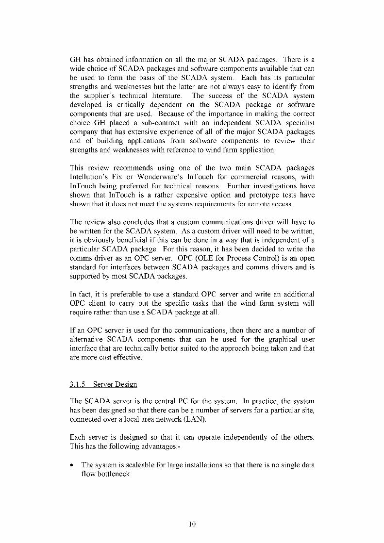
GH has obtained information on all the major SCADA packages. There is a wide choice of SCADA packages and software components available that can be used to form the basis of the SCADA system. Each has its particular strengths and weaknesses but the latter are not always easy to identify from the supplier’s technical literature. The success of the SCADA system developed is critically dependent on the SCADA package or software components that are used. Because of the importance in making the correct choice GH placed a sub-contract with an independent SCADA specialist company that has extensive experience of all of the major SCADA packages and of building applications from software components to review their strengths and weaknesses with reference to wind farm application.
This review recommends using one of the two main SCADA packages Intellution’s Fix or Wonderware’s InTouch for commercial reasons, with InTouch being preferred for technical reasons. Further investigations have shown that InTouch is a rather expensive option and prototype tests have shown that it does not meet the systems requirements for remote access.
The review also concludes that a custom communications driver will have to be written for the SCADA system. As a custom driver will need to be written, it is obviously beneficial if this can be done in a way that is independent of a particular SCADA package. For this reason, it has been decided to write the comms driver as an OPC server. OPC (OLE for Process Control) is an open standard for interfaces between SCADA packages and comms drivers and is supported by most SCADA packages.
In fact, it is preferable to use a standard OPC server and write an additional OPC client to carry out the specific tasks that the wind farm system will require rather than use a SCADA package at all.
If an OPC server is used for the communications, then there are a number of alternative SCADA components that can be used for the graphical user interface that are technically better suited to the approach being taken and that are more cost effective.
3.1.5 Server Design
The SCADA server is the central PC for the system. In practice, the system has been designed so that there can be a number of servers for a particular site, connected over a local area network (LAN).
Each server is designed so that it can operate independently of the others. This has the following advantages:-
• The system is scaleable for large installations so that there is no single data flow bottleneck
10

• The failure of a single server only results in loss of functionality of that server. Other servers will be unaffected
• Failure of the LAN will not stop the system from performing its basic functions
The SCADA servers use Windows NT. Each SCADA server runs a numberof processes, namely
• An OPC Modbus server will be used to handle communications over the site communications network
• A “SCADA Service” will control the polling of the nodes and storing of data in the database via ODBC calls
• An ODBC compliant database. This will store all data recorded from the system
• A database querying and reporting module• A user interface module• A daily task process. This will perform routine tasks such as creating
daily summaries of data, checking data for obvious errors and tidy/backup tasks
3.1.6 Database Selection
There are two main databases within the system, the configuration database and the operational data database.
All database transactions are carried out through ODBC calls. This makes the system independent of any one particular database product as any ODBC compliant database can be used.
Users can select which database they would prefer to use. The selection of database will often depend on the size of project as well as the user’s preferences.
The system has been tested with Access 97 and Microsoft SQL Server 6.5.
Although both databases have ODBC interfaces, some minor differences in the features supported and the syntax used have been identified. None of these differences cause insurmountable problems.
The system has been designed to use multiple databases for scalability and flexibility.
The database is split into two parts, the configuration information and the stored data.
11

3.1.7 Remote Access Options
The system has been designed so that all user interface functions are provided through WEB browsers.
This has the following advantages• Multi-user access• Access from any networked PC. This can either be a PC on a local area
network or a dial-up connection.• No special software or dongles required• Software updates can be implemented centrally with no need to distribute
updates.
PC Anywhere will also be used for administrative purposes.
3.1.8 GUI
The underlying technology for the remote access version of the graphics package is based on ActiveX controls and the data exchange mechanism is based on DCOM.
The use of ActiveX technology restricts remote access to browsers that support ActiveX and this in practice means Internet Explorer. Whilst this is not ideal, the widespread use of Internet Explorer makes this acceptable as an interim solution. It is recognised that this is not a satisfactory solution in the long term.
DCOM is very closely tied to Windows NT security and office tests have shown that it is not practical for remote PC’s to be automatically configured to access information with DCOM. Although it is possible to manually set up an individual PC for remote access, this requires a fair degree of expertise. For this reason it is concluded that DCOM is not suitable for general remote access.
Discussions have been held with the suppliers regards the problems with DCOM. They also recognise that DCOM is not well suited for remote access and are currently working on a solution that avoids the use of DCOM for remote access. It is hoped that this solution will become available by the time the commercial version of the SCADA system is ready.
An alternative Java based package for the GUI has also been investigated. This removes the remote access problems but the package is still in a beta form and has some other shortfalls.
Currently, neither of the two standard packages that have been investigated have proved to be entirely suitable. A custom Java based solution is therefore also being developed in parallel. This option is looking very promising.
12

3.2 System Design - Components
3.2.1 System Overview
An overview of the components of the system is shown in Figure 2.
At the turbines, RlU’s connect to the turbine controllers and communicate with them using the controller protocol.
The RIU’s are connected back to the central SCADA PC over the site network.
There will also be RIU’s for meteorological masts and substations.
The main components at the central PC are as follows:
• An OPC Modbus server is used to handle communications over the site communications network
• A “SCADA Service” controls the polling of the nodes and storing of data in the database via ODBC calls (this is labelled “GH App” on Figure 2)
• An ODBC-compliant database. This stores all data recorded from the system
• A database querying and reporting module• A user interface module• A daily task process. This performs routine tasks such as creating daily
summaries of data, checking data for obvious errors and tidy/backup tasks
The SCADA Service runs all of the time and carries out all of the background tasks. These include:• Polling process• Calling auto control function• Handling operator alerts
The polling process consists of checking the status of each turbine in turn and downloading any statistical and event data. Data are stored in the database. A copy of the current status of each turbine is stored in the OPC server for use by the user interface.
Received events are checked to see if they require an operator alert. If so, the logic for remote alerts is also checked to see if any email, fax or SMS messages need to be sent.
13

3.2.2 Site Configuration Database
The system configuration is stored in a configuration database. This database includes the following:
1. Site definition• Servers in the Wind farm• Communications networks in the wind farm• Electrical circuits in the wind farm• Turbines and turbine groups in the wind farm• Meteorological masts in the wind farm• Substations in the wind farm
2. System Options3. User Options4. Information on Turbine Types
• Power curves• Reactive power curves• Nacelle wind speed corrections
5. Report definitions
The database is used by all parts of the system. It is intended to be configured by the system administrator and so is not accessible through the web-based interface.
A copy is held on each server on the site so that individual servers can function independently. When changes are made to the configuration database, they need to be deployed to all of the servers.
3.2.3 Data Database
The data collected by the system is stored in a data database.
The data collected from the turbines are stored in two types of tables, statistical data tables and event data tables. The statistical data are nominally stored on a 10-minute basis although the actual period is configurable. The statistical data is summarised at the end of each day and daily summary tables are created.
For anything but the smallest system, 10-minute statistical data would soon become unmanageable so it is intended that this would be archived after approximately 6 months.
The daily summary data would be kept active for the duration of the project.
It is recognised that data will need to be edited and corrected from time to time and that this process will need to be traceable. In order to do this, all records in the statistical tables (10-minute and daily summary) have a “valid from”
14

and “valid to” field. When records are created, their “valid from” field is set to the current time and their “valid to” field set to the future.When a record is edited a copy of the record is made. The “valid to” date of the original record is set to be the edit time. The copy has its “valid from” field set to the edit time and the “valid to” field set to the future.
All of the reporting processes use the “valid from” and “valid to” fields to select the currently valid data.
3.2.4 Modbus Interface
The modbus address space has been defined to allow a standard interface to turbines. Methods have been developed to allow file transfers in both directions and to allow system commands to be sent to the RIU’s.
Queue handling routines have been developed to allow handling of statistical and event data.
3.2.5 Turbine States, Commands and Availability Definitions
Definitions have been developed for all statistical calculations and for calculation of availability. The definition and calculation of availability has been identified as a major requirement of manufacturers, operators and owners. A full discussion of availability is presented in Appendix 1.
Further discussions have taken place with project partners on the use of the availability data that is collected.
One requirement that has emerged from these discussions is the need to be able to override the data that has been recorded in some instances in order to either include or exclude it for availability purposes. It had originally been assumed that editing the recorded data would do this.
However, a more convenient way of doing this would be to include an override field in each record that would allow the recorded record to be automatically processed.
3.2.6 Security
Controlled access to the system will obviously be important for most users. This includes access to the system both on site and remotely. The system has been designed so that access to the different components of the system can be configured by the system administrator on a per-user basis.
The security makes use of Windows NT’s built in security model and extends to both local and remote access. Users are given Windows NT logins and a
15

number of predefined groups are set-up to allow access to various parts of the system.
16

4. TESTING
4.1 Office Testing
The system has undergone extensive office-based testing. The system set-up in the office consisted of two NT servers, Carno and Carno1, which were configured as follows:
• Server Carno• Access 97 Database• Com1: 1 Real RIU connected to Bonus 600 controller• Com2: 64 simulated RIU’s
• Server Carno 1• SQL Server 6.5 Database• Com 1: 64 simulated RIU’s
The real RIU consisted of the actual target hardware and was connected to an actual Bonus 600 controller. The Bonus 600 controller did not have any I/O signals connected to it so although it provided data in the correct format, the values of the data were not meaningful.
The simulated RIU’s would collect data and respond to all system commands and were used to realistically simulate site communications, network traffic and system loading.
The two servers were connected to GH’s internal LAN and were also provided with a dial-up connection. This allowed the system to be tested from the local servers, from a PC on a LAN and over a dial-up connection.
The following tests were carried out:
• Basic Operation- Correct restart after power loss- Correct download of software and configuration files from server to
RIU- Stable memory usage at server- Timing of poll loops- Correct data collection at RIU’s- Correct operation of queues- Correct transfer of statistical and event information from RIU to
database- Correct time keeping
• User Interface- Correct transfer of commands- Check of all information published by RIU and server
17

• Reporting- Check power curve against independent calculation- Check wind speed distribution against independent calculation.- Check daily summary calculations
• Data Browsing- Viewing of data, exercising all options.
• Remote Access- Browser access to system for local and dial-up connections- Operation with IE4, IE5 and Netscape 4.6 browsers
4.2 Site Tests
Two periods of site tests were carried out at the Carno wind farm. The server was installed at the substation on site and an RIU installed at turbine B1.
The first test period was 24 to 28 July 2000. During the week the system was connected to a turbine during the day with staff on site. The following were successfully tested:
• Communication with the turbine• Correct interpretation of and presentation of turbine information• Correct calculation and logging of statistical data• Correct operation of Stop, Reset and Release to Run commands• Correct operation of crew present switch• Communications from substation to B1 using spare multiplexor channel• Dial in through new SCADA phone line.
The system was reconnected for a second period during 13 to 22 December 2000. The system was left connected continuously during this period with no staff on site. The period of testing was used to verify
• Operation over an extended period• Data collection over an extended period• Dial in access to the system from a number of locations
18

5. SPECIFICATION
A system specification has been developed and is included as Appendix 2.
This gives an overview of the system and details of specific features from a user’s point of view.
6. FURTHER WORK
Some work remains to be carried out on the system. GH has been working with a user interface designer to finalise the layout of the user interface. This is now complete and the agreed changes will be incorporated into the system.
A graphic designer will be used to design icons and to select colour schemes and fonts.
Work has begun on writing the documentation and manuals for the system and for marketing of the system.
This is expected to act as a focus to finalise the system into a commercial product.
It is envisaged that the system will be continuously updated to incorporate users requirements. Users have already expressed interest in more advanced data analysis capability and incorporating operations and maintenance records in the database. Other areas of interest are condition monitoring and energy forecasting.
19

7. EXPLOITATION AND DISSEMINATION OF RESULTS
The potential applications for the generic SCADA system are all wind farms. The system is being developed specifically for wind farms but could potentially be used for other renewable energy projects.
There is expected to be a large number of offshore wind farms installed in the near future and the SCADA system is being developed with this in mind.
7.1 Market Study
Since every wind farm built has the potential requirement for a SCADA system the market for the system is potentially very large. 4000MW were installed in 1999 and the market is growing at up to 40% per year. The cumulative capacity achieved by 2004 is estimated to be around 50,000MW. Some of this capacity will continue to be single turbines that do not require a SCADA system but the trend is towards more and larger wind farms. Countries like Germany and Denmark, which have traditionally been dominated by single turbine market, are reaching saturation for this sort of development and are now looking to large offshore projects. The new offshore developments in Europe represent a major opportunity for wind farm SCADA system development.
In total, it is estimated there will be a potential market for SCADA systems in the next three years worth a total value of approximately □ 54,000,000. It is difficult to estimate the share of the market that the developed system will achieve but it is considered that 10 to 20% should be possible.
SecondWind, an American company, offer a SCADA system similar to the Garrad Hassan system that is independent of the wind turbine and of the wind turbine controller. The American developer/operator Seawest developed their own system in conjunction with an independent SCADA manufacturer. Zond, currently the largest American manufacturer has also developed its own system. Fenway has developed a system for the Kenetech plant in America that has also been adapted to communicate with NEG Micon turbines.
Informal discussions have been held with potential clients for the system. Turbine manufacturers, developers, operators, owners and O&M companies have all shown interest.
20

7.2 Value Analysis Study
The generic SCADA software will provide the following additional functionality over existing systems:
• Common user interface• User-definable reporting• Common data formats• Improved remote access
The generic SCADA package will be priced to provide the additional functionality at costs below that of existing systems.
The use of remote interface units connected to a basic network will allow the following additional functionality:
• Connection with all wind turbine types• Facilities for providing additional I/O• Facilities for condition monitoring• Improved use of network and tolerance of network faults• Facility for remote download of software• Improved ability of direct connection to third party equipment
For wind farms using the fibre-optic based Ethernet option the following additional functionality will be available:
• Use of network for remote access to SCADA system• Use of network for connection of additional equipment (e.g. barcode
readers, additional monitoring equipment)• Facility for high-speed datalogging over site network• Use of network for voice communications• Use of network for video
7.3 Protection of Results
It has been agreed amongst the project partners that GH will own all rights to the SCADA system developed in this project. Bonus will retain the rights to the protocol for its turbine controller but will grant a licence for its use to GH.
21

7.4 Exploitation Strategy
The project has developed a generic SCADA system with integrated facilities for O&M procedures that will enable the cost of energy from wind farms to be reduced. Operational data provided by the SCADA system will lead directly to improved maintenance scheduling of wind farms, better machine and farm performance, and contribute to improvements to machine components.
The key deliverable is the developed generic wind farm SCADA system. This will be of interest to all of the project partners for future wind farms.
The project is of strategic importance for GH because of the company’s aim to extend its machine monitoring product range and services. The SCADA system will be a natural extension to the company’s T-MON system that is widely used within the industry for performance and load measurements. GH plans to market the system vigorously to all wind farm developers and manufacturers. On completion of the project GH plans to extend immediately the number of different turbines to which the system can interface to cover all the major commercial manufacturers. Discussions with other wind turbine manufacturers have been very encouraging with a number agreeing to provide the protocols for their wind turbines and the remainder considering the matter. NWP and IVPC will also have considerable leverage with turbine manufacturers to provide the protocols for their turbines and a clear incentive to apply it.
22

8. REFERENCES
1. “Development of a Generic Wind Farm SCADA System”, ETSU Agreement No W/45/00526/00/00.
2. G Smith. “Generic Wind Farm SCADA System Requirements Specification”. Garrad Hassan specification 2228/GS/01, Issue 002, 6 January 1999.
3. Cotton, I and Jenkins, N, "Lightning Protection of Wind Turbines", UMIST, CEU Joule Project - JOR3-CT95-0052, November 1996.
4. “Measuring Footprints of Wind Turbine Fatigue Loads Using Monitoring Methods”, European Commission DG XII JOR3-CT96-0103.
23

9. GLOSSARY
Active X ActiveX® controls are a type of software component. They are a development of OLE controls and provide a number of enhancements specifically designed to allow distribution over high-latency networks and to provide integration of controls into Web browsers.
CSCD Carrier Sense Collision Detect. CSCD is a method used to control access to a network by a number of independent nodes. A device which wants to use the network first checks to see if the network is being used (Carrier Sense) and then transmits its message if the network is not being used. During transmission it checks that its message has not been corrupted by another node deciding to transmit at the same time (Collision Detect).
comms An abbreviation for Communications.DCOM Distributed Component Object Model. The Distributed
Component Object Model (DCOM) is a protocol that enables software components to communicate directly over a network in a reliable, secure, and efficient manner. Previously called "Network OLE," DCOM is designed for use across multiple network transports, including Internet protocols such as HTTP. DCOM is based on the Open Software Foundation's DCE-RPC spec and will work with both Java applets and ActiveX® components through its use of the Component Object Model (COM).
DEWI Deutsches Windenergie-Institut GmbH.DLL Dynamic Link Library. DLLs are compiled libraries that can be
called by other programs under the Windows operating system. DLLs can be written in a variety of languages.
DOS Disk Operating System. Used to refer to MS-DOS or compatible operating systems.
Force Majeure Unforeseeable and exceptional course of events or circumstance beyond either parties’ control and which cannot be reasonably avoided or overcome. May include but is not limited to war, invasion, rebellion, terrorism, revolution, insurrection, military or usurped power or civil war, riot, commotion, disorder, strike or lockout, ionising radiation or contamination by radio-activity, explosives, radiation or radio-activity and natural catastrophes such as earthquake, hurricane, typhoon or volcanic activity. Excusing from fulfilment of contract.
IE4 Internet Explorer 4.IE5 Internet Explorer 5.I/O Input/Output.IVPC Italian Vento Power Corporation.LAN Local Area Network.MEASNET MEASurement NETwork. An international network for
harmonised and recognised measurements in wind energy. A European Renewable Energy Centres Agency (EUREC-Agency) activity.
Modbus A communications protocol for simple master-slave networks.
24

NWP National Wind Power.ODBC Open Database Connectivity (ODBC) is a widely accepted
application programming interface (API) for database access. It uses Structured Query Language (SQL) as its database access language.
OLE Object Linking and Embedding (OLE) is a compound document standard developed by Microsoft Corporation. It enables you to create objects with one application and then link or embed them in a second application. Embedded objects retain their original format and links to the application that created them. Support for OLE is built into the Windows and Macintosh operating systems.
OPC The OPC (OLE for Process Control) Specification is a nonproprietary technical specification that defines a set of standard interfaces based upon Microsoft’s OLE/COM technology. The application of the OPC standard interface makes possible interoperability between automation/control applications, field systems/devices and business/office applications.
OSI Open System Interconnection (OSI), an ISO standard for worldwide communications that defines a networking framework for implementing protocols in seven layers. Control is passed from one layer to the next, starting at the application layer in one station, proceeding to the bottom layer, over the channel to the next station and back up the hierarchy.
PC 104 PC 104 is a interface standard for industrial PC cards. Electronically it is the same as the standard PC ISA bus but it uses different, stackable connector system.
RIU Remote Interface Unit.RS232 Standard for point to point serial data communications based on
single wire per signal.RS422 Standard for point to point serial data communications based on
differential signals (2 wires per signal).RS485 Standard for serial data communications which allows a number of
nodes to share the same bus. Based on differential signals (2 wires per signal).
SCADA Supervisory Control and Data Acquisition.SQL Structured Query Language (SQL) is a language for querying
relational databases.TCP/IP Transmission Control Protocol/Internet Protocol. A protocol for
routing packets of data across a network. It is the basic protocol for almost all LANs and for the internet.
UMIST University of Manchester Institute of Science and Technology.Windows NT Microsoft’s server operating system.
25


□Remote Access
y x y x y x y x y x
□Central PC
y \___________ / \___________ / \___________ / \___________ z x
Site Comms Network
y X y x y x y x y x
_y x_Sub
StationMetMast
Figure 1. General Arrangement of Generic Wind Farm SCADA System
27

Graphical Remote Access via PC AnyWhere
GraphicalUser
Interface
SCADA Server
Turbine Protocol Modbus;
PublishedWEBPages
Email/Pager/
Fax
RIU
GUIModule
ODBCDatabase
Server
GH App
OPC/ModbusDriver
TurbineController
WEB Browser Access
GH WEB Based
Reporting
(Optional)
Figure 2. Generic Wind Farm SCADA Components
28

APPENDIX A
AVAILABILITY DEFINITION
A1

INTRODUCTIONThis document defines a consistent way for measuring and recording wind turbine event and performance data by the Garrad Hassan SCADA system and calculating wind turbine availability. The definitions and logic defined in this document are generic and independent of any one turbine type.
Availability figures are important in operational and contractual terms for turbine suppliers, wind farm developers, wind farm owners and wind energy financial institutions. However, the definition of availability is not often well defined and can lead to confusion and contractual uncertainties.
It is recognised that there is a requirement to tailor definitions to suit turbine types, warranty agreements and operating agreements/strategies. In order to do this definitions need to be generic and unambiguous. They must also depend on transparent, traceable and realistic measurements. The Garrad Hassan methodology is to provide a set of mutually exclusive time categories to cover all reasonably possible wind farm operating states. These are then used to provide a set of default availability definitions along with the option for users to create their own defined availabilities from these time categories.
DISCUSSION OF AVAILABILITYIt is useful to consider by whom and for what purpose availability figures arecalculated.
1 By the wind farm operator as a performance indicator for individual turbines and the whole wind farm including balance of plant items. Used for calculation of revenue reimbursement under agreed contractual terms if turbines fail to meet a warranted availability level. May also be used for bonus payments if turbines exceed an agreed availability level.
2 By the turbine supplier as a performance indicator for their turbines and proof of meeting contractual obligations regarding availability warranties. Suppliers of turbines define a warranted power curve that also implicitly defines the wind speed range over which the turbine will generate. They also specify the grid conditions and temperature ranges over which the turbine will operate.
3 By the wind farm developer when considering turbine selection and calculating predicted energy yields for the wind farm.
Developers calculate expected energy yields by combining warranted power curves with the expected wind speed distribution for the site. The resulting annual expected energy figure is then multiplied by the turbine availability figure to make allowances for scheduled
A2

maintenance, grid availability and an assumed number of turbine faults.
The availability figure is therefore very important in the financial modelling of a wind farm. The underlying assumption here is that the turbine availability figure represents the percentage of time that the generator is on line when the wind speed, grid and temperature are within specified limits. It is also assumed to be independent of all other variables and that the periods of unavailability are evenly distributed over wind speeds.
The importance of the figure is underlined by the fact that developers usually specify the required availability in turbine supply contracts and apply penalties for failing to achieve the contracted figure.
4 By the financial institutions involved in wind energy project finance. The process of due diligence will include inspection and assessment of the warranted availability, an evaluation of suitable availability figures to be used for the financial model and the effect this will have on the expected revenues.
It can be seen that there are a number of different requirements for availability figures. Owners, operators and turbine suppliers will tend to favour calculation methods that reflect their own needs.
Availability has traditionally been simply defined as the proportion of time the turbine is generating power or is ready to produce power when the meteorological (primarily wind) conditions are within the specified operational limits of the wind turbines. This is generally known as ‘Wind Availability’.
Wind Availability = time turbine is generating or ready to generate time wind conditions suitable for generation
An owner may however favour a more overall definition of availability that does not take into account the wind conditions. From the owner’s perspective availability may be simply seen as a measure of the time the turbine was generating during a given time period. The owner tends to look more at the wind farm as a single power plant.
The turbine supplier naturally tends toward a definition that is limited to parameters directly within the control of the turbine. All parties recognise that there are a number of conditions which prevent the turbine from generating but which are not the fault of the turbine. These include grid faults, stoppages due to operational (utility and planning) constraints and stoppages ordered by
A3

the owner for non-operational reasons such as training or visitors. The turbine supplier will not include these stoppages in a calculation of availability.
Furthermore there are other possible causes of lost production, which are not currently considered in availability calculations. These are turbine conditions which prevent generation but which are not reported as faults. They are sometimes recorded as warnings that the turbine is engaged in a normal operational activity. The following are examples of this category:
Cable unwindsHold-down timers which delay turbine starts after particular operations Time to startTime to change speed (for two speed turbines)
Although these conditions should not amount to a significant amount of time, this is not always the case and they may cause disputes to arise.
Garrad Hassan has defined a number of availability terms, categories and calculations in order to be as generic as possible and give flexibility to all parties to define availability to meet their needs. These are described in the following sections.
A4

DEFINITION OF TERMS
Specific terms used by Garrad Hassan in the recording and calculation of availability are defined below.
Released to RunThe turbine has been released to run by the wind farm operator and is operating under the automatic control of the turbine controller. It is ready to generate when temperature, wind and grid conditions are within operating limits. The turbine may be On Line or Off Line.
On LineThe turbine generator is connected to the grid. The turbine may be generating or consuming electrical energy.
N.B. It is assumed that the turbine is generating electrical energy in accordance with the turbine specifications. However, it is recognised that there are a number of situations in which the turbine may be ‘On Line’ but not generating in accordance with the turbine specifications particularly the warranted power curve. Examples are:
Turbine running with blade tips partially deployed Turbine blades not pitched correctly Turbine not yawing into the wind correctly Turbine not switching between generators correctly Turbine blades fouled (dirt, bugs, ice)Turbine blades damagedTurbine blades aerodynamic modification devices not functioning correctlyGenerator and gearbox losses greater than specified
However the ability of the SCADA system to determine these situations will depend to a large extent on the level of sensors fitted to the turbines. Currently turbine suppliers do not necessarily fit sensors to automatically determine these conditions. Reliance should be made on power curve analysis and maintenance records made manually on site to detect these conditions. Automatic trips could be set if the difference between the warranted power and actual power exceeded a given level. Ultimately the owner/operator may switch off a turbine displaying these faults and categorise the downtime in agreement with the supplier.
Off LineThe turbine is grid connected but the generator is off line. The turbine may be importing energy (controllers, lights, heaters etc.) but the generator is disconnected. The turbine may be carrying out an automatic control function (cable unwind, generator change etc.) or automatically stopped and in the process of an auto restart operation.
A5

Wind In LimitsThe wind speed as seen by the nacelle anemometer controlling the turbine is within the agreed operational limits for the turbine. This wind speed may be corrected according to individual anemometer calibration factors and for the effects of nacelle and rotor on the airflow as agreed between the owner and the turbine supplier. Different corrections may be used depending on whether the turbine is generating or off line.
To avoid figures being biased by delays in starting and stopping, the limits used to test whether the wind speed is in limits may be defined as slightly different to the warranted power curve limits. The limits used would be agreed on a project-by-project basis taking into account hysteresis in restart settings particularly after resets.
Wind Out LimitsThe wind speed as seen by the nacelle anemometer controlling the turbine is outside the agreed operational limits for the turbine. This wind speed may be corrected according to individual anemometer calibration factors and for the effects of nacelle and rotor on the airflow as agreed between the owner and the turbine supplier. Different corrections may be used depending on whether the turbine is generating or off line.
To avoid figures being biased by delays in starting and stopping, the limits used to test whether the wind speed is in limits may be defined as slightly different to the warranted power curve limits. The limits used would be agreed on a project by project basis taking into account hysteresis in restart settings particularly after resets.
Ambient TemperatureAmbient temperature may be measured at a suitable point within the wind farm or on individual turbines. Stoppages for ambient temperature being outside of operational limits are assumed to be relatively infrequent. It is also assumed that the temperature is reasonably constant over a site and changes slowly or at least can be assumed to be constant over a ten-minute period.
Turbine EventA turbine event is any event that causes a change in the operational status of the turbine. It may be a control event, fault event, stop or other clearly defined change that triggers a change in the turbine state. Events have a clearly defined time.
Fault StopThe turbine has stopped automatically due to a fault condition detected by the turbine controller. The turbine will not restart automatically but requires manual intervention either remotely through the SCADA commands or from a crew present at the turbine.
Maintenance StopThe turbine has been stopped for scheduled or unscheduled maintenance.
A6

Operator StopThe turbine has been stopped by the operator either at the turbine or remotely from the SCADA system. Operator stop counts against availability by default. If the operator has been asked to stop the turbine by the owner then either a constraint stop should be used or operator records would be used to assign the downtime appropriately.
Constraint (Owner) StopThe turbine is stopped by the owner due to constraints such as curtailment, time of day or noise stoppages ordered by the local regulatory authority or the utility. A constraint stop may also be agreed with the turbine supplier to reduce array turbulence effects on closely spaced turbines in wind farms. These stops may be pre-programmed into the SCADA system or made manually.
Grid Limits StopThe turbine is stopped because the grid is unavailable or outside the agreed operational limits.
Remote Interface Unit (RIU)Remote Interface Units (RIU) are independent SCADA units fitted at each turbine, meteorological mast and grid metering point. In the turbines these units are connected between the turbine controller and the site communications network. They have local processing and storage capability.
No CommsNo communications from the turbine controller to the turbine RIU. The RIU is functioning correctly.
AVAILABILITY TIME CATEGORIES
In order to calculate availability figures the GH SCADA system divides turbine time into fifteen mutually exclusive categories. The time (seconds) spent in each of these categories is recorded every 10 minutes. The time categories are summarised in the Table A1.
A flow chart showing the decision process for assigning time into the fifteen mutually exclusive availability categories is shown as Figure A1.
A7

Table A1Availability Time Categories
AvailabilityCategory
Time Status
No SCADA t1 The SCADA system (central computer, communications network or RIU) is not functioning correctly. Note that data lost due to temporary computer or network problems will be restored from the RIU when the problem is fixed. Total data loss will therefore be due either to an RIU failure or a grid outage.
Force Majeure t2 Force Majeure condition exists on the wind farm.
No Comms t3 The SCADA communications system is functioning correctly but no data communication is available from the turbine controller.
On Line t4 Turbine generator on line.
Grid Limits Stop t5 The grid is outside agreed operational limits.
AmbientTemperature Stop
t6 The wind farm ambient temperature is outside the agreed turbine operational limits.
Off LineWind In Limits
t7 Turbine is released to run and wind is within operational limits but turbine generator is off line. This may be due to turbine operations such as cable unwinds and generator changes.
Off LineWind Out Limits
t8 Turbine is released to run but generator is off line due to wind conditions being outside the operational limits.
Fault StopWind In Limits
t9 Turbine is stopped with a turbine fault requiring operator intervention. Wind is within operational limits.
Fault StopWind Out Limits
t10 Turbine is stopped with a turbine fault requiring operator intervention. Wind is outside operational limits.
Maintenance Stop Wind In Limits
t11 Turbine is stopped for scheduled or unscheduled maintenance. Wind is within operational limits.
Maintenance Stop Wind Out Limits
t12 Turbine is stopped for scheduled or unscheduled maintenance. Wind is outside operational limits.
Operator StopWind In Limits
t13 Turbine is stopped by operator command. Wind is within operational limits.
Operator StopWind Out Limits
t14 Turbine is stopped by operator command. Wind is outside operational limits.
Constraint Stop t15 Turbine is stopped for operational constraints (time of day, noise etc). May be manual or preprogrammed.
A8

Figure A1
Flow Chart of Availability Time Categories
A9

AVAILABILITY CALCULATIONS.
The availability may be calculated over any time period. The Garrad Hassan generic wind farm SCADA system offers six default availabilities which are detailed below. The user may define up to ten of their own availability calculations based on the addition, subtraction and division of the availability time categories.
The following definitions are the default calculations.
TIME (T) = Total time (seconds) in period for which availability is to be calculated.
SCADA AVAILABILITY:
TIME - No SCADATIME
= (T - t1) /T
This represents the proportion of time for which reliable data is available. It may seem that No Comms (t3) should be included in this definition. However if the RIU is working but there is no information coming from the turbine controller the assumption is that the turbine is not working and is therefore unavailable. The RIU will return data indicating the turbine is unavailable.
GRID AVAILABILITY:
TIME - No SCADA - Grid Limits StopTIME
= (T - t1 - t5) / T
This represents the proportion of time during which the grid was available (on line and within agreed operating limits). The inclusion of No SCADA (t1) is based on the assumption that a SCADA failure to collect any reliable data is caused by a total grid loss. This would be confirmed by checking of grid loss with the utility.
A10

SITE AVAILABILITY:
TIME - No SCADA - Force Majeure - Grid Limits Stop - Ambient Temperature Stop - Constraint Stop
TIME
= (T - t1 - t2 -t5 - t6 - t15) / T
This represents the proportion of time during which the site conditions (physical and operational) were suitable for the turbines to be in the Released to Run state. The inclusion of t1 is based on the assumption that a SCADA failure to collect any reliable data is caused by a total grid loss. This would be confirmed by checking of grid loss with the utility.______________________
TURBINE SUPPLIER AVAILABILITY:
On Line + Off Line Wind In Limits + Off Line Wind Out Limits TIME - No SCADA - Force Majeure - Grid Limits Stop - Ambient Temperature Stop - Constraint Stop - Fault Stop Wind Out Limits - Maintenance Stop Wind Out Limits - Operator Stop Wind Out Limits
= (t4 + t7 + t8) / (T - t1 - t2 -t5 - t6 - t15 - t10 - t12 - t14)
This represents the time during which the turbine was generating or ready to generate given suitable wind conditions as a proportion of the time site conditions were suitable for generation. It is a figure that quantifies how well the turbines are performing when viewed from the supplier’s perspective.
No SCADA is assumed to be indicative of a grid failure. Inclusion of Fault Stop Wind Out Limits, Maintenance Stop Wind Out Limits and Operator Stop Wind Out Limits act as an incentive to supplier/operator to schedule work outside wind limits to increase the turbine supplier availability figure.
Off Line Wind In Limits is included in recognition that the turbine spends some time carrying out normal control operations such as cable unwinds. However this may be qualified by agreeing a cap on the amount of time allowed before it starts to count as unavailable during this time.
A11

TURBINE OWNER AVAILABILITY:
On Line + Off Line Wind Out Limits TIME - No SCADA - Force Majeure - Grid Limits Stop - Ambient
Temperature Stop - Constraint Stop
= (t4 + t8) / (T - t1 - t2 -t5 - t6 - t15)
This represents the time during which the turbine was generating or ready to generate given suitable wind conditions as a proportion of the time site conditions were suitable for generation. It is a figure that quantifies how well the turbines are performing when viewed from the owner’s perspective. No SCADA is assumed to be indicative of a grid failure._____________________
TURBINE & WIND FARM AVAILABILITY:
On Line + Off Line Wind out of LimitsTIME
= (t4 + t8) / T
This represents the time during which the turbine was generating or ready to generate given suitable wind conditions as a proportion of the total time for which the calculation is performed. It is a figure that quantifies how well the wind farm is performing as a percentage of the theoretical maximum as viewed from the owner’s perspective._________________________________
A12

SCADA SYSTEM LOGICLogic for deriving which of these categories the turbine is in is given in the following section. It depends on the following information being available from the turbine.
1. Grid available and within specified limits2. Turbine Faulted3. Turbine On Line4. Measurement of nacelle wind speed5. Turbine Released to Run
It is assumed that the turbine can be controlled in the following ways:
1. Operator control via SCADA system with the commands:Operator Stop Operator Release to Run Operator Reset
2. Operator control at the turbine with the commands:Operator Stop Operator Release to Run Operator Reset
3. Automatic control by the SCADA system with the commands:Run Command Stop Command Reset Command Set Constraint Stop Clear Constraint Stop
The following flags are maintained by the SCADA system.
1. Maintenance Stop flag (crew present)2. Operator Stop flag Set/Cleared by SCADA system3. Constraint Stop flag Cleared by Release to Run commands from
SCADA or Turbine. Set by Stop commands from SCADA or Turbine
To avoid conflicts between operator control via the SCADA system and operator control at the turbine, a crew present (or maintenance mode) is provided. This has two positions, normal and crew present.
If the switch is in the crew present position, only an operator at the turbine will be able to reset and release a turbine to run. If it is in the normal position, operators will only be able to reset and release a turbine to run from the SCADA system.
A13

With the switch in the crew present position it is recognised that the SCADA system would be unable to prevent local reset and start commands. For safety reasons, the turbine can be stopped either at the turbine or via the SCADA system regardless of the position of the switch.
From the point of view of the SCADA system, it is assumed that the operator commands at the turbine are not necessarily directly detectable and that only tests of whether the turbine is released to run and whether it is faulted are available.
A14

APPENDIX B
SYSTEM SPECIFICATION
B1

INTRODUCTION
The Generic Wind Farm SCADA System has been designed by Garrad Hassan in collaboration with turbine manufacturers, wind farm operators, wind farm developers and financiers to meet the needs of all parties concerned with wind farm performance.
Garrad Hassan was established in 1984 and rapidly established itself worldwide as a leading independent consultancy in wind energy. Garrad Hassan has made measurements on a large number of wind turbines using its monitoring system, T-MON, and has experience of wind turbine design, SCADA systems and data analysis from numerous wind farm projects.
This background and skill base allied to Garrad Hassan’s completely independent and impartial status means that this is a SCADA system that can be relied on to be totally independent, traceable and transparent in it’s operation.
Garrad Hassan staff are available to discuss customer requirements and to design, install and commission a system with the minimum fuss and maximum back up. Garrad Hassan’s commitment to wind energy guarantees long term system support.
Key benefits of the system are:
• Completely independent, traceable and transparent in operation. The users specify what they want to see, control, record and report.
• Independent turbine, grid and meteorological station remote interface units providing maximum data integrity.
• Easy remote access requiring only a Web Browser. No complex software set ups or dongles required.
• Easily customised to meet the different needs of turbine manufacturers, wind farm developers, wind farm operators, wind farm owners and financiers.
• Operates seamlessly with machines from any wind turbine manufacturer.
• Common graphical interface allowing users to have a common front-end display to all their wind farms.
• Common reporting enabling users to produce reports with the same format for all their wind farms.
• Common format for the database allowing the same data processing to be used for wind farms with different makes of turbine.
• Validated comparison of actual to expected energy and revenue output using wind farm power curve produced by Garrad Hassan WindFarmer the industry-leading software.
B2

• Grid and sub station interface units for control and monitoring of the wind farm electrical system.
• Meteorological station interface units for independent wind speed and meteorological parameter monitoring and analysis.
• Inclusion of condition monitoring in O&M records with input to preventative maintenance (in development).
• Integration of O&M operations into the SC ADA system control and database (in development).
SYSTEM OVERVIEW
The system consists of a central SCADA computer connected to each turbine, meteorological station and grid station using a site network as shown below. The system is expandable so that several SCADA computers can be networked together for large wind farms. There is no limit to the number of turbines that can be monitored with the system.
Utility HV Grid SCADA Computer Remote ComputerSite Sub Station
System Overview
B3

Remote Interface UnitsA key feature of the system is the Remote Interface Unit (RIU) at each turbine, meteorological station and grid station. In the turbines these units are connected between the turbine controller and the site communications network. They have local processing and storage and provide the following benefits:
• Data sample rate is independent of the site communications network and depends only on the speed of communication of the turbine controller. The higher sampling rate improves the accuracy of the summary statistics that are produced.
• Processed data can be stored locally in a queue so that no data is lost if the site communications network is temporarily unavailable. When the network is available, the queue is downloaded to the SCADA computer.
• The RIU provides a common interface to the wind farm, allowing different turbines to have the same interface.
• The RIU can provide additional functionality that is not included in the standard turbine controllers. All turbine events can be logged.
• The RIUs can be expanded to provide additional I/O so that additional sensors can be connected to the system. This may include noise monitoring stations and safety and access control equipment.
• Software updates automatically downloaded from the SCADA computer.
• Configuration information downloaded from the SCADA computer.
• Clock automatically corrected to central SCADA computer clock.
• Provision of Crew Present switch.
Site Communications NetworkThe site communications network is based on Modbus an industry standard protocol. It can operate on the simplest of networks but will be able to use the faster TCP/IP networks when these become cost effective for wind farm use.
The SCADA computer system runs on Windows NT and is built from software components using standard open interfaces (OPC, OBDC and Web technology).
B4

Local and Remote AccessAll local and remote user access is through standard web browsers allowing multi-user access and easy remote access.
Local users can access the system through a Web Browser on the SCADA PC or on any other networked PC.
Remote users can dial into the system from any PC with a modem and web browser (Internet Explorer, Netscape Navigator) without requiring any extra software or dongles.
Remote AlertsThe system can be configured to alert staff via mobile phone, pager, fax or email if any part of the wind farm requires attention.
This feature can be configured to operate continuously for unmanned sites or only during certain times of day as required.
SecuritySecurity is based on standard NT security and can be customised to meet the requirements of particular sites. The following groups are defined
• View real time status only• View real time status and allow commands• View real time status and access historical data• View real time status, allow commands and access historical data• View real time status, allow commands, access historical data and set-up
configuration access.• Full system administration access
Time Base and Date FormatsTime and date formats have been chosen to eliminate confusion arising from different time zones, summer/winter changes and different country display formats.
• All time stamps apply to the end of a period.• All time stamps are stored as UTC, regardless of local time setting used.• All times are displayed with the time zone to which they apply.• All dates are entered and displayed in the form “dd mmm yyyy”, e.g. 13
Sep 2000.
Data Back UpFull data back up facilities are provided based on CD ROM or tape drives as appropriate.
B5

SYSTEM FUNCTIONS
Control CommandsThe system allows local or remote control of individual turbines or groups of turbines.
System configuration allows for any number of user-defined groups of turbines.
In addition a number of predefined groups are automatically created• All turbines on site• All turbines connected to a grid circuit• All turbines connected to a particular PC• All turbines connected to a particular communications port
The following commands can be issued to turbines either individually or to a pre-defined group of turbines
• Release to Run• Stop• Reset
Stop and Release to Run commands are ignored if there is a crew at the turbine. Any commands issued locally at a turbine will override the SCADA system if there is a crew present. If there are no crew present, commands from the SCADA system will override the current turbine setting.
Commands to groups of turbines can optionally be staggered.
Command requests are queued so that if there are no communications to the turbine when the command is issued, it will be applied when communications return.
The system can implement auto control of the turbines. This allows automatic implementation of any constraints on wind farm operation (e.g. network restrictions, noise restrictions, time of day restrictions). A standard DLL interface is provided and the user can either implement the required control function or Garrad Hassan can provide a DLL to meet user requirements.
On Line Data ViewingThe user is able to monitor the wind farm current status through either a graphical user interface (GUI) showing a map-based representation of the wind farm or a series of tables summarising turbine, meteorological station and grid station status.
The GUI provides a top-level view of the wind farm with facilities to link to particular groups or units. Units are represented by icons identifying the unit
B6

type and name and conveying the equipment status as the user scans the wind farm. The screen incorporates a geographical map as a backdrop showing contours, vegetation, buildings and roads etc.
Commands are instantly available on selecting a unit or group of units from the map.
Direct links are available from the GUI icons to the corresponding tabular summary screens.
A single top-level tabular screen shows the complete site status at a glance. Clearly defined areas of the screen show turbines, meteorological stations, grid stations and current events. The turbine status shows turbines on line, faulted, stopped, crew present, power and energy outputs. The meteorological status shows the site mean wind speed, direction, temperature, pressure and air density. The grid status shows the grid power and energy output for the wind farm, site electrical loss and overall production efficiency.
Current site events are clearly shown at the bottom of the screen with event code, event description, response status and times.
Links are highlighted to detailed information screens on individual turbines, meteorological stations and grid stations.
The user has a choice between a ‘snapshot’ screen and a ‘dynamic’ screen. A snapshot screen shows the status of each unit on the wind farm at the time the screen was requested. A dynamic screen continuously updates the information from the wind farm while the screen is in view. At all times 10-minute average data values are stored in the working database for further analysis.
Configuration information for any unit on the wind farm and the system can be displayed by simple selection of that unit.
Historical Database ViewingTen-minute performance data and all event data are stored in an industry- standard relational database. Any ODBC compliant database can be used. The data is time stamped when received at the server and a record of the number of readings used to calculate all statistics is maintained. This ensures complete traceability of stored and edited data.
The user may browse the ten-minute data and events database and show the events for any unit for any time period.
B7

The system allows the user complete freedom in browsing the database but the more common selections are catered for in drop down menu’s.
• Browse Event Data Allows user to view turbine and wind farm event data with options to
Select turbine or group of turbinesInclude events from grid stations, meteorological stations and serversSelect time rangeList all events or show totals only
• Browse 10-minute data Allows user to browse through 10-minute data for a selected turbine, meteorological station or grid station.
• Trend view Allows user to view time series data for up to 10 selected signals. These signals can come from any turbine, meteorological station or grid station.
• Current value of signal across group Allows user to view the current value of a signal across a group of turbines.
• Past value of selected of signals across group Allows user to view values of selected signals at a point in time from the database.
ReportsSummary analysis reports are produced on demand or automatically at set times. They provide extensive analysis and viewing functions for statistical and event data.
Any number of user-defined report formats can be created. When producing a report, the user can select
• Report type• Unit or group of units• Date range
Reports can either be shown immediately or queued for delivery by email. Autogeneration of reports for specified groups of units (daily, weekly, monthly or annual) is easily programmed.
Power CurvesPower curves may be created for any user selectable date range with a selectable wind speed bin size and choice of binned or scatter data.
Power Curves are generated according to IEC 61400-12 and include the following options:
• Application of speed-up factors• Include Standard Error information• Air density correction:
- to specified value- based on measured temperature and pressure data, record by record- based on measured temperature and pressure data, average
correction for period• Wind direction exclusion sectors
B8

• Exclusion of records where icing occurred• Filtering of data based on:
- minimum sample rates- minimum number of readings- record length
Power Curves may be generated using nacelle or any meteorological station wind speed signal. It is possible to apply user-specified corrections to nacelle anemometer readings to obtain the free stream wind speed.
Power curves can be either shown immediately or queued for delivery by email at a later date. Facilities are also provided to queue a batch of Power Curves reports for groups of turbines.
Meteorological DataMeteorological data may be analysed according to wind speeds, wind direction, turbulence, temperature, pressure, density and other data from any installed sensors. This includes frequency distributions, and analysis of mean, maximum and minimum data.
Distributions can be created over any user selectable date range with a selectable bin size and choices of binned or scatter data. They may be generated from any meteorological station or nacelle anemometer with optional correction of nacelle wind speeds.
Results can either be shown immediately or queued for delivery by email.
Energy ProductionThe actual, expected and planned energy production for individual turbines, groups of turbines or the whole wind farm for any time period to date.
Expected energy output is calculated using the wind farm power curve produced by the WindFarmer code, the industry leading validated wind farm performance prediction software.
Energy lost during periods of downtime according to wind speed and warranted power curve may also be determined.
EventsEvents are any changes in the status of a unit. They are time stamped and stored in the relational database. They may then be analysed by unit, time or event and linked where appropriate to turbine performance and meteorological data. Time, energy and revenue lost due to particular events may be easily calculated.
B9

AvailabilityAvailability calculations are made on definitions that are generic, transparent, unambiguous and based on realistic measurements. All turbine time is recorded and assigned to fifteen mutually exclusive categories. The availability may be calculated over any time period.
Availability Category Time StatusNo SCADA T1 The SCADA system is out of operation.Force Majeure T2 Force Majeure condition exists on the wind
farmNo Comms T3 The SCADA communications system is
functioning correctly but no datacommunication is available from the turbine controller.
On Line T4 Turbine generator on line.Grid Limits Stop T5 The grid is outside agreed operational limits.Ambient Temperature T6 The wind farm ambient temperature is outsideStop the agreed turbine operational limitsOff Line T7 Turbine is released to run and wind is withinWind In Limits operational limits but turbine generator is off
line. This may be due to turbine operations such as cable unwinds and generator changes.
Off Line T8 Turbine is released to run but generator is offWind Out Limits line due to wind conditions being outside the
operational limits.Fault Stop T9 Turbine is stopped with a turbine faultWind In Limits requiring operator intervention. Wind is
within operational limits.Fault Stop T10 Turbine is stopped with a turbine faultWind Out Limits requiring operator intervention. Wind is
outside operational limits.Maintenance Stop T11 Turbine is stopped for scheduled orWind In Limits unscheduled maintenance while the wind is
within operational limits.Maintenance Stop T12 Turbine is stopped for scheduled orWind Out Limits unscheduled maintenance while the wind is
outside operational limits.Operator Stop T13 Turbine is stopped by operator commandWind In Limits while the wind is within operational limits.Operator Stop T14 Turbine is stopped by operator commandWind Out Limits while the wind is outside operational limits.Constraint Stop T15 Turbine is stopped for operational constraints
(time of day, noise etc). May be manual or pre-programmed.
Default calculations are supplied with the system. In addition the user may define their own availability calculations based on the addition and division of these time categories.
B10

B11