Embed Size (px)
Citation preview
Development of a Fan for Future Space Suit Applications
Heather L. Paul, NASA, Johnson Space CenterDavid Converse, Steven Dionne, Hamilton Sundstrand, Space, Land & Sea
Jeff Moser, Sierra Nevada Corporation, SpaceDev Division
Abstract
NASA's next generation space suit system will place new demands on the fan used tocirculate breathing gas through the ventilation loop of the portable life support system.Long duration missions with frequent extravehicular activities (EVAs), the requirementfor significant increases in reliability and durability, and a mission profile that imposesstrict limits on weight, volume and power create the basis for a set of requirements thatdemand more performance than is available from existing fan designs.
This paper describes the development of a new fan to meet these needs. A centrifugalfan was designed with a normal operating speed of approximately 39,400 rpm to meetthe ventilation flow requirements while also meeting the aggressive minimal packaging,weight and power requirements. The prototype fan also operates at 56,000 rpm tosatisfy a second operating condition associated with a single fan providing ventilationflow to two spacesuits connected in series. This fan incorporates a novel nonmetallic"can" to keep the oxygen flow separate from the motor electronics, thus eliminatingignition potential. The nonmetallic can enables a small package size and low powerconsumption. To keep cost and schedule within project bounds a commercial motorcontroller was used. The fan design has been detailed and implemented usingmaterials and approaches selected to address anticipated mission needs. Test data ispresented to show how this fan performs relative to anticipated ventilation requirementsfor the EVA portable life support system. Additionally, data is presented to showtolerance to anticipated environmental factors such as acoustics, shock, and vibration.Recommendations for forward work to progress the technology readiness level andprepare the fan for the next EVA space suit system are also discussed.
Introduction
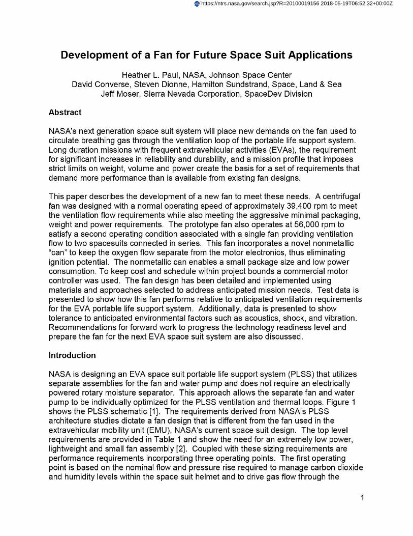
NASA is designing an EVA space suit portable life support system (PLSS) that utilizesseparate assemblies for the fan and water pump and does not require an electricallypowered rotary moisture separator. This approach allows the separate fan and waterpump to be individually optimized for the PLSS ventilation and thermal loops. Figure 1shows the PLSS schematic [1]. The requirements derived from NASA's PLSSarchitecture studies dictate a fan design that is different from the fan used in theextravehicular mobility unit (EMU), NASA's current space suit design. The top levelrequirements are provided in Table 1 and show the need for an extremely low power,lightweight and small fan assembly [2]. Coupled with these sizing requirements areperformance requirements incorporating three operating points. The first operatingpoint is based on the nominal flow and pressure rise required to manage carbon dioxideand humidity levels within the space suit helmet and to drive gas flow through the
https://ntrs.nasa.gov/search.jsp?R=20100019156 2018-05-19T06:52:32+00:00Z
Portable Life Support. System (PLSS) Pressure Garment System (PGS)
ry A ^.'^C^4{ ^ CLrtnp^t A^
.UM
OxygenSubsystem
b
ventilation loop. As this operating point is the only one with a known powerrequirement, it is the aerodynamic design point for this fan and is termed the "DesignPoint." The second operating point has been termed the "Buddy Point" and isassociated with a failure condition of one PLSS so that a single fan drives flow throughtwo space suits connected in series via an umbilical. The final point, called the"Maximum Flow Point" is based on an alternate space suit design that requires a higherflow rate in the ventilation loop than the baseline PLSS design.
,^,^t m
r O PrsSbura Sensor ,^} Prexsve sore or tdual r Ckiresrrgdef + I=] readout
Fels' • r4n eqw (^ Fft Twrcwadure ,^,^ Prossure Regurator..r Q FOuTomperature Sensor E Test Port
1 Pressty ambient 9J CeNfol VekHarde H Vane
_> ROWtre Gauge
Regubbe 9)00ntrolor^aFiler - How
'̂ siTr600mtrgi An PU*IMtygh
td^ ouick0*corrroct ^ FM
KYRequiaw
6r^4Pressrre to wrbont Filer D OWkVhha^^Aayusbndv. Maior =Carbon D-D de Ssmor ID F- -qw— 00 SolemidVetre •0 Nang VWe RCA Valves Mated Webs ^ PWW
(Note: Line replaceabte unit ILRUI fillings and filters not shown — idenliliers for inters not shown.)
Figure 1: PLSS Schematic with Fan Identified [1]
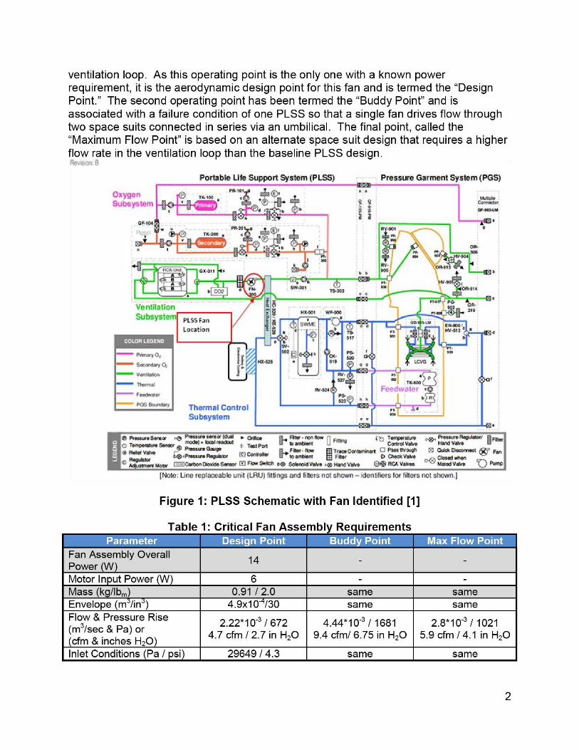
Table 1: Critical Fan Assemblv Reauirements
Fan Assembly Overall14 - -
Power WMotor Input Power (W) 6 - -Mass (kg/lb,) 0.91 / 2.0 same sameEnvelope (m /in) 4.9x10 /30 same sameFlow & Pressure Rise(M3/sec & Pa) or
2 22*10-3 / 672 4.44*10-3 / 1681 2.810-3 / 10214.7 cfm / 2.7 in H 2O 9.4 cfm/ 6.75 in H 2O 5.9 cfm / 4.1 in H2O
cfm &inches H2OInlet Conditions (Pa / psi) 29649/4.3 same same
2
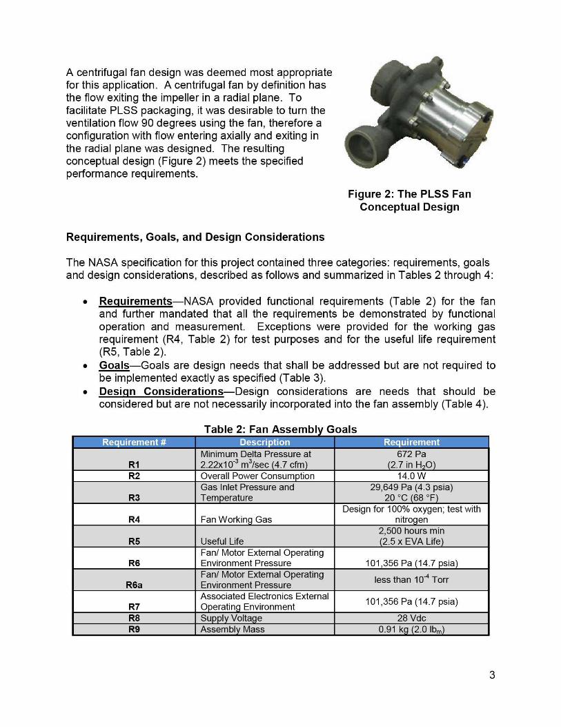
A centrifugal fan design was deemed most appropriatefor this application. A centrifugal fan by definition hasthe flow exiting the impeller in a radial plane. Tofacilitate PLSS packaging, it was desirable to turn theventilation flow 90 degrees using the fan, therefore aconfiguration with flow entering axially and exiting inthe radial plane was designed. The resultingconceptual design (Figure 2) meets the specifiedperformance requirements.
Figure 2: The PLSS FanConceptual Design
Requirements, Goals, and Design Considerations
The NASA specification for this project contained three categories: requirements, goalsand design considerations, described as follows and summarized in Tables 2 through 4:
• Requirements—NASA provided functional requirements (Table 2) for the fanand further mandated that all the requirements be demonstrated by functionaloperation and measurement. Exceptions were provided for the working gasrequirement (R4, Table 2) for test purposes and for the useful life requirement(R5, Table 2).
• Goals—Goals are design needs that shall be addressed but are not required tobe implemented exactly as specified (Table 3).
• Design Considerations—Design considerations are needs that should beconsidered but are not necessarily incorporated into the fan assembly (Table 4).
Table 2: Fan Assemblv GoalsE614-radJ!y^I
Minimum Delta Pressure at 672 PaR1 2.22x10⁻³ m 3/sec 4.7 cfm 2.7 in H20R2 Overall Power Consumption 14.0 W
Gas Inlet Pressure and 29,649 Pa (4.3 psia)R3 Temperature 20 °C 68 °F
Design for 100% oxygen; test withR4 Fan Working Gas nitrogen
2,500 hours minR5 Useful Life 2.5 x EVA Life
Fan/ Motor External OperatingR6 Environment Pressure 101,356 Pa 14.7psia)
Fan/ Motor External Operating less than 10 -4 TorrR6a Environment PressureAssociated Electronics External 101,356 Pa (14.7 psia)R7 Operating Environment
R8 Supply Voltage 28 VdcR9 Assembly Mass 0.91 k 2.0 lbm
3
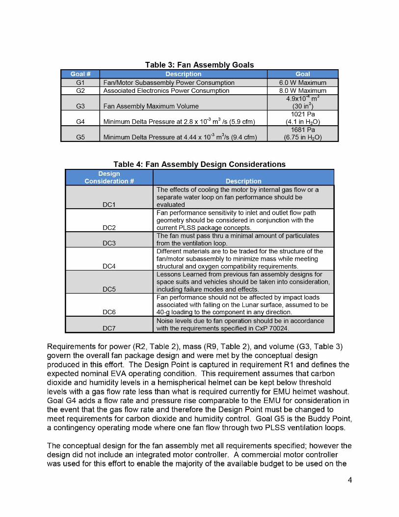
Table 3: Fan Assembly Goals.. .;r ddKCZ.G1 Fan/Motor Subassembly Power Consumption 6.0 W MaximumG2 Associated Electronics Power Consumption 8.0 W Maximum
4.9x10- mG3 Fan Assembly Maximum Volume 30 in3
1021 PaG4 Minimum Delta Pressure at 2.8 x 10⁻³ m 3 /s 5.9 cfm 4.1 in H20
1681 PaG5 Minimum Delta Pressure at 4.44 x 10 -3 m 3/s 9.4 cfm 6.75 in H20
Table 4: Fan Assembly Design Considerations
The effects of cooling the motor by internal gas flow or aseparate water loop on fan performance should be
DC1 evaluatedFan performance sensitivity to inlet and outlet flow pathgeometry should be considered in conjunction with the
DC2 current PLSS package concepts.The fan must pass thru a minimal amount of particulates
DC3 from the ventilation loop.Different materials are to be traded for the structure of thefan/motor subassembly to minimize mass while meeting
DC4 structural and oxygen compatibility requirements-Lessons Learned from previous fan assembly designs forspace suits and vehicles should be taken into consideration,
DC5 including failure modes and effects.Fan performance should not be affected by impact loadsassociated with falling on the Lunar surface, assumed to be
DC6 40-g loading to the component in any direction.Noise levels due to fan operation should be in accordance
DC7 with the requirements specified in CxP 70024.
Requirements for power (R2, Table 2), mass (R9, Table 2), and volume (G3, Table 3)govern the overall fan package design and were met by the conceptual designproduced in this effort. The Design Point is captured in requirement R1 and defines theexpected nominal EVA operating condition. This requirement assumes that carbondioxide and humidity levels in a hemispherical helmet can be kept below thresholdlevels with a gas flow rate less than what is required currently for EMU helmet washout.Goal G4 adds a flow rate and pressure rise comparable to the EMU for consideration inthe event that the gas flow rate and therefore the Design Point must be changed tomeet requirements for carbon dioxide and humidity control. Goal G5 is the Buddy Point,a contingency operating mode where one fan flow through two PLSS ventilation loops.
The conceptual design for the fan assembly met all requirements specified; however thedesign did not include an integrated motor controller. A commercial motor controllerwas used for this effort to enable the majority of the available budget to be used on the
4
Beari n c2 place!
fan design and testing. Hamilton Sundstrand has design numerous space qualifiedmotor controllers and no unusual issues are foreseen with future design of an integratedmotor controller for this fan.
Fan Design
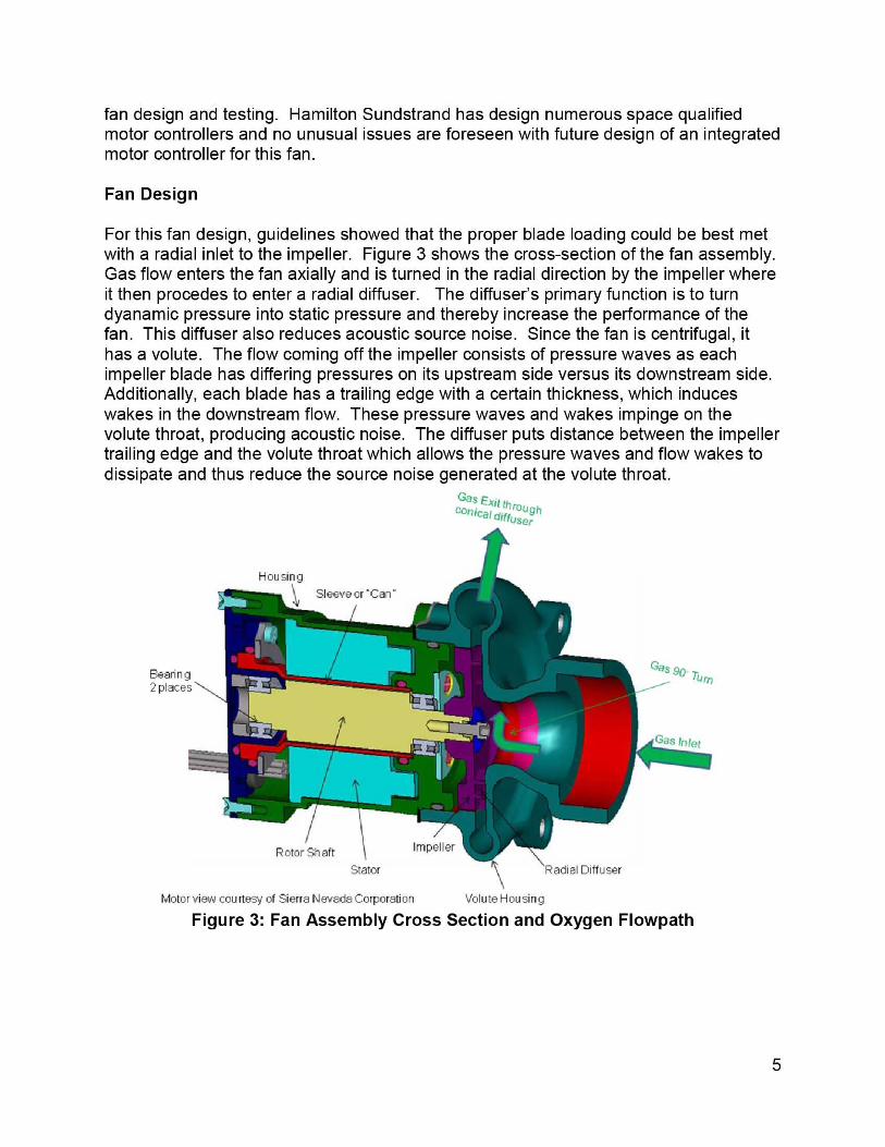
For this fan design, guidelines showed that the proper blade loading could be best metwith a radial inlet to the impeller. Figure 3 shows the cross-section of the fan assembly.Gas flow enters the fan axially and is turned in the radial direction by the impeller whereit then procedes to enter a radial diffuser. The diffuser's primary function is to turndyanamic pressure into static pressure and thereby increase the performance of thefan. This diffuser also reduces acoustic source noise. Since the fan is centrifugal, ithas a volute. The flow coming off the impeller consists of pressure waves as eachimpeller blade has differing pressures on its upstream side versus its downstream side.Additionally, each blade has a trailing edge with a certain thickness, which induceswakes in the downstream flow. These pressure waves and wakes impinge on thevolute throat, producing acoustic noise. The diffuser puts distance between the impellertrailing edge and the volute throat which allows the pressure waves and flow wakes todissipate and thus reduce the source noise generated at the volute throat.
Vas Exit throughcomical diffuser
Motor view courtesyOf Sierra Nevada Corporation volute Housing
Figure 3: Fan Assembly Cross Section and Oxygen Flowpath
5
NMII ) e, I
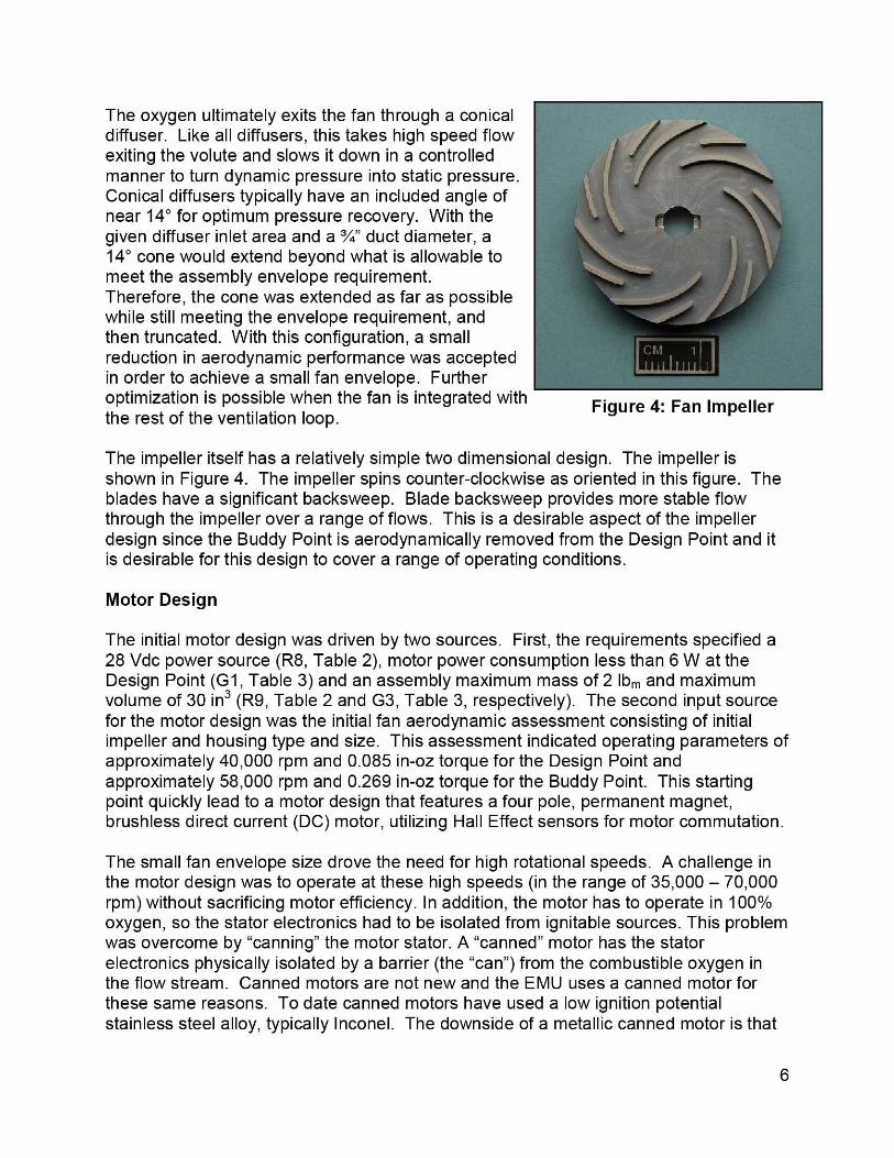
Figure 4: Fan Impeller
The oxygen ultimately exits the fan through a conicaldiffuser. Like all diffusers, this takes high speed flowexiting the volute and slows it down in a controlledmanner to turn dynamic pressure into static pressure.Conical diffusers typically have an included angle ofnear 14 0 for optimum pressure recovery. With thegiven diffuser inlet area and a %" duct diameter, a14° cone would extend beyond what is allowable tomeet the assembly envelope requirement.Therefore, the cone was extended as far as possiblewhile still meeting the envelope requirement, andthen truncated. With this configuration, a smallreduction in aerodynamic performance was acceptedin order to achieve a small fan envelope. Furtheroptimization is possible when the fan is integrated withthe rest of the ventilation loop.
The impeller itself has a relatively simple two dimensional design. The impeller isshown in Figure 4. The impeller spins counter-clockwise as oriented in this figure. Theblades have a significant backsweep. Blade backsweep provides more stable flowthrough the impeller over a range of flows. This is a desirable aspect of the impellerdesign since the Buddy Point is aerodynamically removed from the Design Point and itis desirable for this design to cover a range of operating conditions.
Motor Design
The initial motor design was driven by two sources. First, the requirements specified a28 Vdc power source (R8, Table 2), motor power consumption less than 6 W at theDesign Point (G1, Table 3) and an assembly maximum mass of 2 Ibm and maximumvolume of 30 in (R9, Table 2 and G3, Table 3, respectively). The second input sourcefor the motor design was the initial fan aerodynamic assessment consisting of initialimpeller and housing type and size. This assessment indicated operating parameters ofapproximately 40,000 rpm and 0.085 in-oz torque for the Design Point andapproximately 58,000 rpm and 0.269 in-oz torque for the Buddy Point. This startingpoint quickly lead to a motor design that features a four pole, permanent magnet,brushless direct current (DC) motor, utilizing Hall Effect sensors for motor commutation.
The small fan envelope size drove the need for high rotational speeds. A challenge inthe motor design was to operate at these high speeds (in the range of 35,000 — 70,000rpm) without sacrificing motor efficiency. In addition, the motor has to operate in 100%oxygen, so the stator electronics had to be isolated from ignitable sources. This problemwas overcome by "canning" the motor stator. A "canned" motor has the statorelectronics physically isolated by a barrier (the "can") from the combustible oxygen inthe flow stream. Canned motors are not new and the EMU uses a canned motor forthese same reasons. To date canned motors have used a low ignition potentialstainless steel alloy, typically Inconel. The downside of a metallic canned motor is that
6
Motor Controller - Front
the motor experiences losses in efficiency due to the presence of metal in the magneticfield between the motor stator and the rotor magnets. Existing canned motors havecompensated for this by allowing the motor to consume more power to overcome theselosses. However, the baseline PLSS has a very limited power budget. This fan couldnot utilize a traditional canned motor approach and meet its requirements. To avoidthese canning losses, a non-metallic can design was explored that would still providethe hermetic seal to isolate the stator electronics but avoid the losses caused bymetallic cans. Several candidate materials were considered for the can and ultimatelyzirconia was selected because it machines easily, is durable, and could provide a goodsurface finish for sealing.
A rolling element bearing is located at either end of the motor to simplify the balanceand assure smooth operation. The Hall Effect Device (HED) boards are located at theend of the motor and, for convenience; the electrical harness is routed out the back ofthe motor. Both aluminum and stainless steel were evaluated for the housing and 300series stainless steel was chosen for dimensional control, corrosion resistance, andbecause the weight impact was small due to the small overall package size. The fullyassembled motor weighs only 0.72 Ibm.
Motor Controller
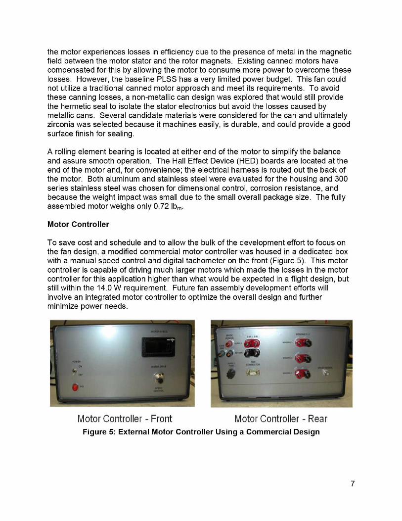
To save cost and schedule and to allow the bulk of the development effort to focus onthe fan design, a modified commercial motor controller was housed in a dedicated boxwith a manual speed control and digital tachometer on the front (Figure 5). This motorcontroller is capable of driving much larger motors which made the losses in the motorcontroller for this application higher than what would be expected in a flight design, butstill within the 14.0 W requirement. Future fan assembly development efforts willinvolve an integrated motor controller to optimize the overall design and furtherminimize power needs.
i';^' cerr[a
Motor Controller - RearFigure 5: External Motor Controller Using a Commercial Design
7
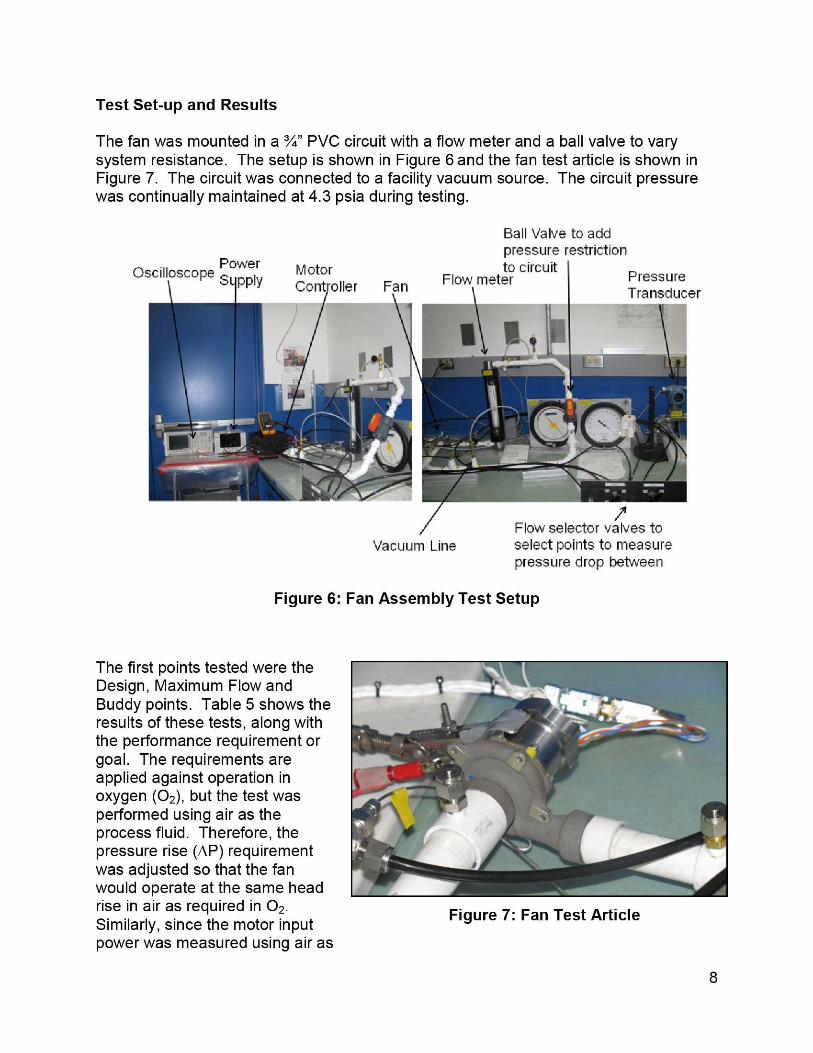
Figure 7: Fan Test Article
Test Set-up and Results
The fan was mounted in a %" PVC circuit with a flow meter and a ball valve to varysystem resistance. The setup is shown in Figure 6 and the fan test article is shown inFigure 7. The circuit was connected to a facility vacuum source. The circuit pressurewas continually maintained at 4.3 psia during testing.
Ball Valve to addpressure restriction
Oscilloscope Power Motor to circuit
p I PressureS^
pp Y Controller Fan Flow meterTransducer
n
Flow selector valves toVacuum Line select points to measure
pressure drop between
Figure 6: Fan Assembly Test Setup
The first points tested were theDesign, Maximum Flow andBuddy points. Table 5 shows theresults of these tests, along withthe performance requirement orgoal. The requirements areapplied against operation inoxygen (0 2), but the test wasperformed using air as theprocess fluid. Therefore, thepressure rise (AP) requirementwas adjusted so that the fanwould operate at the same headrise in air as required in 02.Similarly, since the motor inputpower was measured using air as
8
the process fluid, power was adjusted to account for operation in 0 2 . This adjustment isprovided in Table 5.
Table 5: Fan Performance at Specified Fan Oneratina Points^- ^f
m . e
r- Flow (cfm) 4.7 5.9 9.4d _E 0 02 AP in. H 2 O 2.70 4.10 6.75
L L Air AP (in. H2 O) 2.44 3.71 6.12LT OIX Motor Input Power, 0 2 W 6.0 -- --
Speed (rpm) 39,404 51,350 72,736Motor Input Power W 4.30 8.08 20.08
Motor Efficiency 51.6% 57.9% 62.1%Aero Efficiency 61.8% 56.3% 54.8%
Estimate Motor Input Power, 02 W 4.75 8.91 22.15
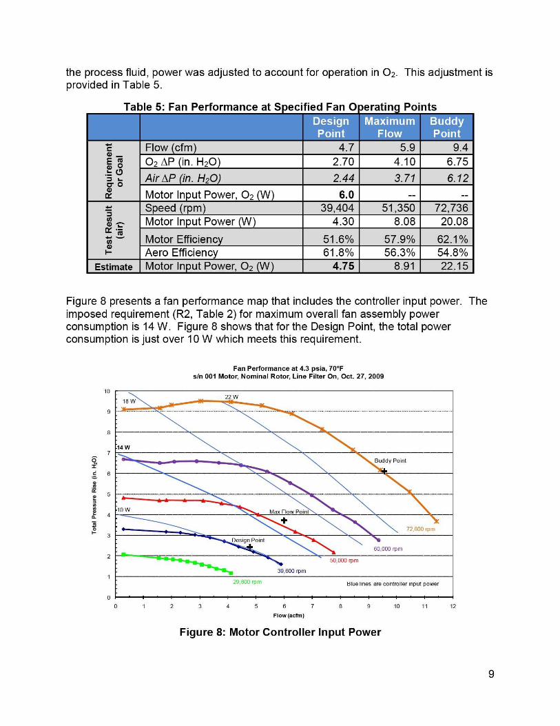
Figure 8 presents a fan performance map that includes the controller input power. Theimposed requirement (R2, Table 2) for maximum overall fan assembly powerconsumption is 14 W. Figure 8 shows that for the Design Point, the total powerconsumption is just over 10 W which meets this requirement.
Fan Performance at 4.3 psia, 70°Fsin 001 Motor, Nominal Rotor, Line Filter On, Oct. 27, 2009
22 W
18 W
14 W
Buddy Point
ow Max Flow Point
72,800 rpm
Design Point
60,000 rpm
50,000 rpm
39,600 rpm
29 ; 800 rpm Blue lines are controller input power
0
0
1 2 3 4 5 6 7 8 9 10 11 12
Flow (acfm)
Figure 8: Motor Controller Input Power
10
9
8
7
O2c 6
mN_
m 5
N
CL
4
R8
~ 3
2
9
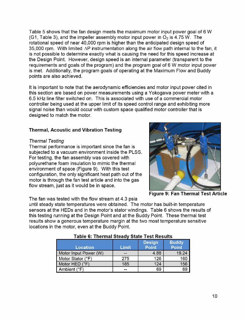
Figure 9: Fan Thermal Test Article
Table 5 shows that the fan design meets the maximum motor input power goal of 6 W(G1, Table 3), and the impeller assembly motor input power in 0 2 is 4.75 W. Therotational speed of near 40,000 rpm is higher than the anticipated design speed of35,000 rpm. With limited OP instrumentation along the air flow path internal to the fan, itis not possible to determine exactly what is causing the need for this speed increase atthe Design Point. However, design speed is an internal parameter (transparent to therequirements and goals of the program) and the program goal of 6 W motor input poweris met. Additionally, the program goals of operating at the Maximum Flow and Buddypoints are also achieved.
It is important to note that the aerodynamic efficiencies and motor input power cited inthis section are based on power measurements using a Yokogawa power meter with a6.5 kHz line filter switched on. This is associated with use of a commercial motorcontroller being used at the upper limit of its speed control range and exhibiting moresignal noise than would occur with custom space qualified motor controller that isdesigned to match the motor.
Thermal, Acoustic and Vibration Testing
Thermal TestingThermal performance is important since the fan issubjected to a vacuum environment inside the PLSS.For testing, the fan assembly was covered withpolyurethane foam insulation to mimic the thermalenvironment of space (Figure 9). With this testconfiguration, the only significant heat path out of themotor is through the fan test article and into the gasflow stream, just as it would be in space.
The fan was tested with the flow stream at 4.3 psiauntil steady state temperatures were obtained. The motor has built-in temperaturesensors at the HEDs and in the motor's stator windings. Table 6 shows the results ofthis testing running at the Design Point and at the Buddy Point. These thermal testresults show a generous temperature margin at the two most temperature sensitivelocations in the motor, even at the Buddy Point.
Table 6: Thermal Steady State Test Resultsnm Imi -,.'•
Motor Input Power (W) -- 4.88 19.24Motor Stator °F 275 126 160Motor HED °F 185 124 156Ambient (°F) 1-- 1 69 69
10
Tonal Peaks
do Exist
Broadband
Might ExceedNC-52
`p 70.0
60.0Nn 50.0
(L ^9a'40.0
Jy 30.0
0063 125 250 500 1000 2000 4000 8000 16000
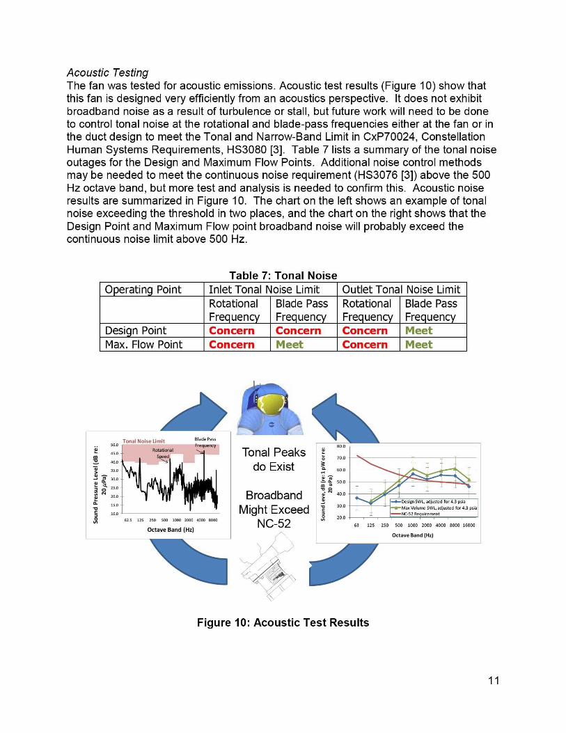
Acoustic TestingThe fan was tested for acoustic emissions. Acoustic test results (Figure 10) show thatthis fan is designed very efficiently from an acoustics perspective. It does not exhibitbroadband noise as a result of turbulence or stall, but future work will need to be doneto control tonal noise at the rotational and blade-pass frequencies either at the fan or inthe duct design to meet the Tonal and Narrow-Band Limit in CxP70024, ConstellationHuman Systems Requirements, HS3080 [3]. Table 7 lists a summary of the tonal noiseoutages for the Design and Maximum Flow Points. Additional noise control methodsmay be needed to meet the continuous noise requirement (HS3076 [3]) above the 500Hz octave band, but more test and analysis is needed to confirm this. Acoustic noiseresults are summarized in Figure 10. The chart on the left shows an example of tonalnoise exceeding the threshold in two places, and the chart on the right shows that theDesign Point and Maximum Flow point broadband noise will probably exceed thecontinuous noise limit above 500 Hz.
Table 7: Tonal NoiseOperating Point Inlet Tonal Noise Limit Outlet Tonal Noise Limit
RotationalFrequency
Blade PassFrequency
RotationalFrequency
Blade PassFre uenc
Design Point Concern Concern Concern FleetMax. Flow Point Concern Meet Concern Meet
r ^.Tonal Noise Limit Blade Pass
500 Frequency
i 95.0 RotationalSpeed
40.0
35.001^ d 30.0iN ^
25.0Ny 20.0
a 15.0V3 10.09, 62.5 125 250 500 1000 2000 4000 8000
Octave Band (Hz)Octave Band (Hz)
Figure 10: Acoustic Test Results
11
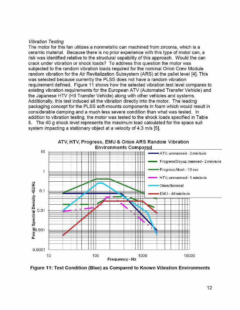
Vibration TestingThe motor for this fan utilizes a nonmetallic can machined from zirconia, which is aceramic material. Because there is no prior experience with this type of motor can, arisk was identified relative to the structural capability of this approach. Would the cancrack under vibration or shock loads? To address this question the motor wassubjected to the random vibration loads required for the nominal Orion Crew Modulerandom vibration for the Air Revitalization Subsystem (ARS) at the pallet level [4]. Thiswas selected because currently the PLSS does not have a random vibrationrequirement defined. Figure 11 shows how the selected vibration test level compares toexisting vibration requirements for the European ATV (Automated Transfer Vehicle) andthe Japanese HTV (HII Transfer Vehicle) along with other vehicles and systems.Additionally, this test induced all the vibration directly into the motor. The leadingpackaging concept for the PLSS soft-mounts components in foam which would result inconsiderable damping and a much less severe condition than what was tested. Inaddition to vibration testing, the motor was tested to the shock loads specified in Table8. The 40 g shock level represents the maximum load calculated for the space suitsystem impacting a stationary object at a velocity of 4.3 m/s [5].
ATV, HTV, Progress, EMU & Orion ARS Random VibrationEnvironments Compared
10 -ATV, unmanned- 2 mm/axis
Progressl50yuz, manned- 2 minla xis
Progress Abort - 10 sec
HTV, unmanned- 1 minlaxis
0.0001
10 100 1000 10000Frequency - Hz
Figure 11: Test Condition (Blue) as Compared to Known Vibration Environments
12
1
Table 8: Shock Input Profile
Terminal Sawtooth 40 g +/- 15% 11 milliseconds
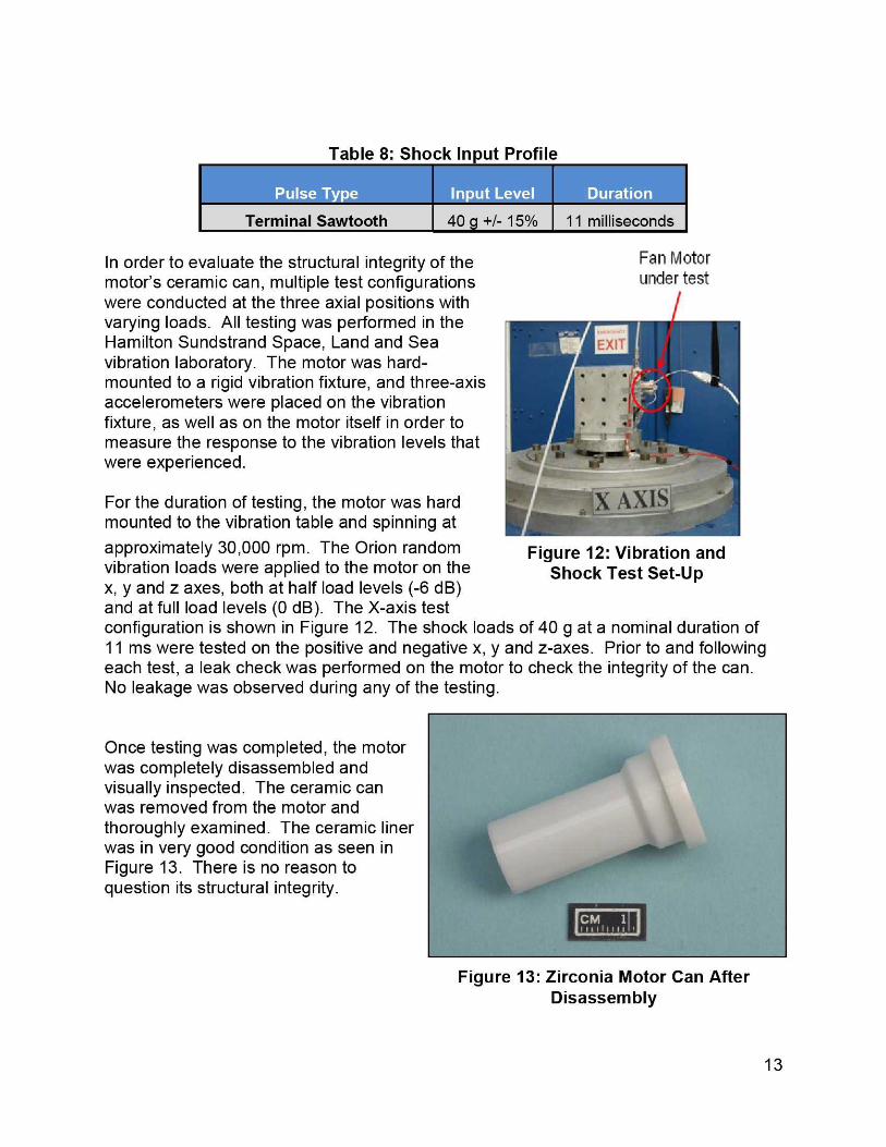
In order to evaluate the structural integrity of themotor's ceramic can, multiple test configurationswere conducted at the three axial positions withvarying loads. All testing was performed in theHamilton Sundstrand Space, Land and Seavibration laboratory. The motor was hard-mounted to a rigid vibration fixture, and three-axisaccelerometers were placed on the vibrationfixture, as well as on the motor itself in order tomeasure the response to the vibration levels thatwere experienced.
For the duration of testing, the motor was hardmounted to the vibration table and spinning at
Fan Motorunder test
approximately 30,000 rpm. The Orion random Figure 12: Vibration andvibration loads were applied to the motor on the Shock Test Set-Upx, y and z axes, both at half load levels (-6 dB)and at full load levels (0 dB). The X-axis testconfiguration is shown in Figure 12. The shock loads of 40 g at a nominal duration of11 ms were tested on the positive and negative x, y and z-axes. Prior to and followingeach test, a leak check was performed on the motor to check the integrity of the can.No leakage was observed during any of the testing.
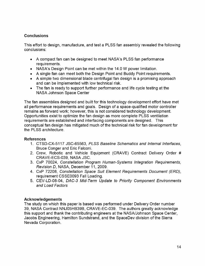
Once testing was completed, the motorwas completely disassembled andvisually inspected. The ceramic canwas removed from the motor andthoroughly examined. The ceramic linerwas in very good condition as seen inFigure 13. There is no reason toquestion its structural integrity.
Figure 13: Zirconia Motor Can AfterDisassembly
13
Conclusions
This effort to design, manufacture, and test a PLSS fan assembly revealed the followingconclusions:
• A compact fan can be designed to meet NASA's PLSS fan performancerequirements.
• NASA's Design Point can be met within the 14.0 W power limitation.• A single fan can meet both the Design Point and Buddy Point requirements.• A simple two dimensional blade centrifugal fan design is a promising approach
and can be implemented with low technical risk.• The fan is ready to support further performance and life cycle testing at the
NASA Johnson Space Center
The fan assemblies designed and built for this technology development effort have metall performance requirements and goals. Design of a space-qualified motor controllerremains as forward work; however, this is not considered technology development.Opportunities exist to optimize the fan design as more complete PLSS ventilationrequirements are established and interfacing components are designed. Thisconceptual fan design has mitigated much of the technical risk for fan development forthe PLSS architecture.
References1. CTSD-CX-5117 JSC-65563, PLSS Baseline Schematics and Internal Interfaces,
Bruce Conger and Eric Falconi.2. Crew, Robotic and Vehicle Equipment (CRAVE) Contract Delivery Order #
CRAVE-ECS-039, NASA JSC.3. CxP 70024, Constellation Program Human-Systems Integration Requirements,
Revision D, NASA, December 11, 2009.4. CxP 72208, Constellation Space Suit Element Requirements Document (ERD),
requirement CSSE0093 Fall Loading.5. CEV-LD-08-04, DAC-3 Mid-Term Update to Priority Component Environments
and Load Factors
AcknowledgementsThe study on which this paper is based was performed under Delivery Order number39, NASA Contract NNJ05HB39B, CRAVE-EC-039. The authors greatly acknowledgethis support and thank the contributing engineers at the NASA/Johnson Space Center,Jacobs Engineering, Hamilton Sundstrand, and the SpaceDev division of the SierraNevada Corporation.
14
ContactsHeather Paul, heather. l.paul(c)- nasa.gov, NASA/Johnson Space Center, Mail Code EC5,Houston TX, (281) 483-3678
Dave Converse, [email protected] , Hamilton Sundstrand, 1 Hamilton Road,Windsor Locks, CT 06096, (860) 654-7079
Steve Dionne, steve.dionne(a-)- hs.utc.com , Hamilton Sundstrand, 1 Hamilton Road,Windsor Locks, CT 06096, (860) 654-4154
Jeff Moser Sierra Nevada Corporation SpaceDev Division,Durham NC, (919) 595-8551 extension 301
15


![Space Suit Portable Life Support System (PLSS) 2.0 … International Conference on Environmental Systems ICES-2016-[86] 10-14 July 2016, Vienna, Austria Space Suit Portable Life Support](https://img.pdfslide.us/doc/110x75/5aee989e7f8b9a6625919962/space-suit-portable-life-support-system-plss-20-international-conference.jpg)