Embed Size (px)
Citation preview

Development of a combined hot isostatic pressing and solution heat-treat process for the cost effective
densification of critical aluminum castings
By:
Matthew M. Diem
A Thesis Submitted to the Faculty of:
WORCESTER POLYTECHNIC INSTITUTE
In partial fulfillment of the requirements for the
Degree of Master
In
Manufacturing Engineering
By
________________________________
December 17, 2002
APPROVED: _________________________________ Richard D. Sisson Jr. Advisor, Professor of Mechanical Engineering Materials Science and Engineering Program Head _________________________________ Christopher A. Brown, Saint Gobain Professor of Mechanical Engineering Director of Manufacturing Engineering
i
Abstract
To minimize the production cost and time of the heat treatment of critical application
aluminum castings within the automotive industry a combined hot isostatic pressing
(HIP)/solution heat treat process is desired. A successfully combined process would
produce parts of equal quality to those produced by the individual processes of HIP and
subsequent heat treatment with increased efficiency in time and energy. In this study, an
experimental combined process was designed and implemented in a production facility.
Industrially produced aluminum castings were subjected to the combined process and
results were quantified via tensile and fatigue testing and microscopic examination.
Comparisons in fatigue and tensile strength were made to traditionally HIPed and heat
treated samples, as well as un-HIPed samples in the T6 condition. Results show that
castings produced with the combined process show fatigue properties that are equal in
magnitude to castings produced with the independent HIP and heat treatment processes.
Furthermore, an order of magnitude improvement in the fatigue life in those castings that
were produced with the combined process exists compared to the castings that were only
heat treated.
This study shows no difference in the tensile properties that result from any of the
processing routes compared. Also, microstructural comparison of the castings processed
show no difference between the process routes other than porosity, which is only evident
in the un-HIPed samples. Dendrite cell size and dendritic structure of the samples that
were solutionized for the same time is identical.
Theoretical examination of the combined process was also completed to quantify the
energy consumption of the combined process compared to the independent processes.

ii
Thermodynamic calculations revealed that the energy consumed by the combined process
for a typically loaded HIP vessel is fifty percent less than the energy required to process
the same quantity of castings with the two individual processes. However, it was
determined that a critical ratio of the volume occupied in the HIP vessel by castings to the
total HIP vessel volume exists that ultimately determines the efficiency of the combined
process. This critical ratio was calculated to be approximately fifteen percent. If the
volume ratio is less than fifteen percent then the combined process is less energy efficient
then conventional processing. These thermodynamic calculations were experimentally
verified with power consumption process data in a production facility.
In addition, the time required for the combined process of HIP and solution heat
treatment was calculated as thirty-percent less than the conventional two-step process.
This calculation was verified via the comparison of data compiled from the experimental
combined process.

iii
Acknowledgements
The author wishes to thank all those involved with the Metal Processing Institute for the
opportunity to partake in this study. To Diran Apelian, Diana Lados and Libo Wang of
Worcester Polytechnic Institute for their expertise in the field of aluminum castings, as
well as the physical contributions that they made to this project.
Thanks to the staff of Bodycote IMT, Inc., in Andover, Massachusetts, and especially
those in the Research and Development department: Jonathan Hall, Jane LaGoy and Dan
Zick.
A heartfelt thank you is also extended to the entire crew at Bodycote IMT, Inc., in
Princeton, Kentucky, notably Charlie Phelps and Mark Robertson, for their tireless
efforts. Thanks are also extended to Doug Bator of Palmer Foundry, Inc. in Palmer,
Massachusetts and James Van Wert, Jr. of Amcast Aluminum.
I would especially like to thank my advisors in this project, Stephen J. Mashl and Richard
D. Sisson, for their advice, guidance and knowledge.
Most of all I would like to thank my wife Christine, for her love, patience and
understanding.

iv
Table of Contents
Abstract…………………………………………………………………………… i
Acknowledgements………………………………………………………………… iii
List of Figures……………………………………………………………………… vi
List of Tables………………………………………………………………………. vii
1. INTRODUCTION………………………………………………………………. 1
2. ARTICLE I – EXPERIMENTAL WORK……………………………………… 5
Abstract…………………………………………………………………………...
1. Introduction…………………………………………………………………….
2. Experimental Procedure………………………………………………………..
2.1. Testing Process Combination Feasibility……………………………………
2.1.1. Materials and Processing…………………………………………………
2.2. Mechanical Property Evaluation…………………………………………….
2.2.1. Materials and Processing…………………………………………………
2.2.2. Industrial Castings Tested………………………………………………...
2.2.3. Mechanical Property Evaluation………………………………………….
3. Discussion and Results………………………………………………………...
3.1. Process Combination Feasibility………………………………………..…..
3.2. Mechanical Property Evaluation…………………………………………….
3.2.1. Commercially Produced ABS Master Cylinder Housing………………...
3.2.2. Experimental Coupon Wedge Castings…………………………………..
3.2.3. Commercially Produced Steering Knuckle…………………..…………...
4. Conclusions…………………………………………………………………….
4.1. Process Combination Feasibility…………………………………………….
4.2. Mechanical Property Evaluation…………………………………………….
5. References……………………………..……………………………………….
6
7
9
12
12
14
14
15
20
20
20
21
21
28
29
32
32
32
34
3. ARTICLE II – THEORETICAL MODELING……………………………….…
Abstract…………………………………………………………………………...
1. Introduction…………………………………………………………………...
2. Procedure……………………………………………………………………..
2.1. Theoretical Framework……………………………………………………...
2.1.1. Identification of Energy Consumption…………………………………...
35
36
36
41
41
41

v
2.1.2. Calculations……………………………………………………………...
2.2. Experimental Verification of Modeling……………………………………
3. Discussion and Results………………………………………………………
3.1. Theoretical Modeling………………………………………………………
3.2. Experimental Verification………………………………………………….
4. Conclusions…………………………………………………………………...
5. References…………………………………………………………………….
45
47
50
50
54
57
58
4. CONCLUSIONS……………………………………………………………….. 60

vi
List of Figures
Article I
Figure 1 – Cast Al-Si-Mg alloy in T6 condition………………………………... 8
Figure 2 – Cast Al-Si-Mg alloy in HIPed T6 condition………………………… 8
Figure 3 – Thermal profile of combined HIP/solution heat treat process versus
Densal + T6 process……………………………………………………………..
11
Figure 4 – Sectioned ABS master cylinder housing..…………………………... 13
Figure 5 – Size and geometry of sand-cast Sr-modified A356 experimental
coupons……………………………………………………………………………
17
Figure 6 – Commercially produced sand-cast Sr-modified A356 steering
knuckle…………………………………………………………………………….
19
Figure 7 – Thermal profile of castings a pressure is vented during process
feasibility study……………………………………………………………………
21
Figure 8 – Microstructure of castings subjected to the combined 4HQ process.. 22
Figure 9 – Fatigue Life as a function of densification process…………………. 24
Figure 10 – Fatigue life as a function of densification process with
superimposed fracture initiation types…………………………………………….
26
Figure 11a, 11b – Micrographs of fracture initiation sites……………………… 27
Figure 12 – S-N fatigue data of sand-cast Sr-modified A356 steering knuckle... 31
Article II
Figure 1 – Fatigue life as a function of processing route 39
Figure 2 – Thermal profile of combined HIP/solution heat treat process versus
Densal + T6 process……………………………………………………………..
40
Figure 3 – Schematic detail of energy consumed by the individual processes… 43
Figure 4 – Schematic detail of energy consumed by combined process……….. 44
Figure 5 – Sectioned ABS master cylinder housing..…………………………... 49
Figure 6 – Theoretical energy consumed by the different processing routes as a
function of the quantity of castings being modeled……………………………….
52
Figure 7 – Theoretical energy consumed by the different processing routes as a
function of the percentage of the HIP vessel occupied by castings……………….
53

vii
Figure 8 – Temperature, furnace power and pressure as a function of time for
one casting…………………………………………………………………………
55
Figure 9 – Temperature, furnace power and pressure as a function of time for
seven castings……………………………………………………………………..
56
List of Tables
Article I
Table I – Chemical composition of ABS master cylinder housing (determined
via ICP-AES)………………………………………………………….…………..
12
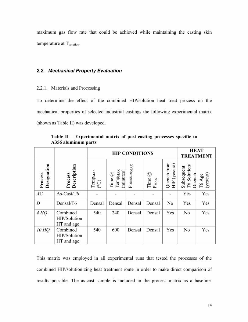
Table II – Experimental matrix of post-casting processing…………………….. 14
Table III – ASM specifications for sand-cast A356 T6 heat treatments……….. 15
Table IV – Chemical composition of experimental coupon wedge castings
(determined via ICP-AES)…………………………………………….………….
18
Table V – Tensile results of ABS master cylinder housing casting……………. 23
Table VI – Tensile results of experimental coupons…………………………… 28
Table VII – Tensile results of sand-cast Sr-modified A356 steering knuckle….. 29
Article II
Table I – Chemical composition of ABS master cylinder housing (determined
via ICP-AES)………………………………………………………….…………..
48
Table II – Properties and results for thermodynamic calculations of one casting
system……………………………………………………………………………..
50
Table III – Properties and results for thermodynamic calculations of seven
casting system……………………………………………………………………..
51

1
1. Introduction
The use of A356 (7%Si, 0.4%Mg) aluminum castings in the automotive industry is
increasing due to the high shape complexity and the good strength-to-weight ratios that
can be obtained with these parts. However, these parts in the as-cast condition are
restricted in the applications in which they can be employed due to poor mechanical
properties. These poor mechanical properties stem from two fundamental issues of the
alloy in the as-cast condition.
The first issue with these castings is caused by inhomogeneity in the casting alloy during
solidification. This non-uniformity is caused by inconsistent cooling within the mold and
leads to an uneven dispersion of coarsely formed precipitates in the alloy matrix. This in
turn leads to poor tensile properties in the as-cast condition.
The second issue inherent in as-cast microstructure is porosity. This porosity is classified
as two distinct varieties, shrinkage porosity and gas porosity. Shrinkage porosity is
caused by the volume of the liquid metal being greater than the volume of the solid metal.
Gas porosity is caused by the high solubility of hydrogen in the liquid aluminum melt and
the tendency for the hydrogen to come out of solution as temperature is reduced. Porosity
is detrimental to the ductility, fracture toughness and fatigue behavior of the casting.
Fortunately, for the casting industry, the issues inherent in the as-cast condition can be
alleviated with post casting processing. Solution heat treating followed by aging is
employed to refine the microstructure of the alloy and improve mechanical and physical
properties. A densification process can eliminate the porosity in the casting.
Heat treatment for cast aluminum alloys starts with a thermal process to solutionize the
alloy matrix, known as solution heat treatment, or solutionizing. Solution heat treatment
2
uses an elevated temperature heat treatment to dissolve the second phase precipitates,
change the morphology of the eutectic silicon phase and make the primary phase a
homogeneous solid solution. In the case of A356, the precipitates are Mg2Si. In order to
prevent the Mg2Si particulates from again precipitating out of solution, a rapid quench is
employed. Quenching the castings also insures that the homogenization that results from
the solutionizing step is maintained. To attain maximum strength in the casting a
precipitation-hardening or aging heat treatment is employed. Artificial aging takes place
at slightly elevated temperatures, 165°C, while natural aging occurs at room temperature.
The homogenization attained in the previous steps insures a uniform dispersion of the
particulates grown in the aging step. Artificial aging to reach maximum strength deems
the temper of the casting as T6, where natural aging gives the casting the temper
designation T4.
Hot isostatic pressing, or HIP, is typically performed before heat treatment and is a means
of eliminating the porosity in castings. HIP surrounds the casting with a pressurized gas,
which applies a hydrostatic force to the surface of the casting while at elevated
temperature to facilitate material flow. The dominant densification mechanism in the
casting during the initial stages of the HIP process is plastic flow. As castings spend
additional time at maximum temperature and pressure the dominant densification
mechanisms change, first to power-law creep, then to diffusional creep mechanisms
(Nabarro-Herring, and Coble creep). The overall effect is the "welding" of isolated
porosity within the casting [Atkinson].
Due to the time intensive nature of the HIP process, several variants of the original
process have been developed to maximize the returns of the HIP process while

3
minimizing process time and cost for the production of critical aluminum castings. Liquid
hot isostatic pressing (LHIP) uses a heated incompressible liquid as the pressurizing
media [Chandley]. The guiding principle behind this manufacturing process states that
the majority of the time spent in the traditional gas HIP process is spent pressurizing and
depressurizing the compressible gas media. In the LHIP process, the castings are
immersed in the liquid salt bath and the entire salt bath container is pressurized via a
hydraulic ram very quickly. By this method, maximum pressure can be reached in
seconds rather then the several hours required in the HIP process. Furthermore, this
process could be integrated into a continuous casting process [Chandley]. However, time
spent at peak pressure for an A356 casting in the LHIP process is only about thirty
seconds [Romano et al.], which does not allow any of the previously mentioned time-
dependant creep mechanisms to occur.
Bodycote PLC has taken another approach to reducing the cost of the HIP process for
aluminum castings. The Densal process is a proprietary HIP process that has tailored the
HIP process specifications and hardware specifically for aluminum castings. Time spent
at temperature and pressure allows diffusional creep mechanisms to take place. It has
been estimated that the Densal process reduces the cost of HIP for aluminum castings
by as much as seventy percent [Mashl et al.]. However, further gains in Densal process
economy may be possible. Due to the similarity of the process temperatures of solution
heat treatment and the Densal process, integrating these two processes could yield even
further reduction in the cost of HIP and heat treatment for aluminum castings.
The purpose of this thesis is to develop and evaluate the feasibility of this combined
Densal + solutionizing process. The bulk of the work completed is included here as two

4
papers to be submitted for publication. Each paper is a stand-alone work with separate
abstract, introduction, procedure, results and discussion, conclusion and reference
sections. The first paper included as Chapter 2 presents the experimental results of the
process combination of Densal and solution heat treatment on several Al-Si-Mg
commercial castings. The second paper, Chapter 3, presents the results of the theoretical
energy calculations of the combined process versus the individual processes of Densal
followed by subsequent heat treatment.

The development of a cost-effective means of producing critical application aluminum castings through simultaneous Densal
and solution heat treatment.
Matthew M. Diem Bodycote IMT, Inc.
WPI
Stephen J. Mashl Bodycote IMT, Inc.
Richard D. Sisson WPI

6
Abstract
To minimize the production cost and time of the heat treatment of critical application
aluminum castings within the automotive industry a combined hot isostatic pressing
(HIP)/solution heat treat process is desired. A successfully combined process would
produce parts of equal quality to those produced by the individual processes of HIP and
subsequent heat treatment with increased efficiency in time and energy. In this study, an
experimental combined process was designed and implemented in a production facility.
Industrially produced aluminum castings were subjected to the combined process and
results were quantified via tensile and fatigue testing and microscopic examination.
Comparisons in fatigue and tensile strength were made to traditionally HIPed and heat
treated samples, as well as un-HIPed samples in the T6 condition. Results show that
castings produced with the combined process show fatigue properties that are equal in
magnitude to castings produced with the independent HIP and heat treatment processes.
Furthermore, an order of magnitude improvement in the fatigue life in those castings that
were produced with the combined process exists compared to the castings that were only
heat treated.
This study shows no difference in the tensile properties that result from any of the
processing routes compared. Also, microstructural comparison of the castings processed
show no difference between the process routes other than porosity, which is only evident
in the un-HIPed samples. Dendrite cell size and dendritic structure of the samples that
were solutionized for the same time is identical.
The experimental combined process also showed significant time savings within the
scope of this production experiment.

7
1. Introduction
Aluminum casting represents an inexpensive method of producing parts with high shape
complexity, excellent strength-to-weight ratios, and good corrosion resistance. For these
reasons the use of aluminum castings in the automotive industry is on the rise. However,
most aluminum alloys in the as-cast condition do not display the mechanical properties
necessary for many applications, and therefore require subsequent heat treatment to
optimize the microstructure of the alloy [1]. Furthermore, with the increased use of
aluminum castings in cyclically stressed applications such as automotive suspension
systems, maximizing the fatigue life of the heat-treated components becomes
increasingly important. Densification, or the elimination of porosity inherent in the
castings, is paramount in the production of fatigue-resistant parts, as pores are most often
the fatigue-limiting characteristic in the casting. [2-6]. To date, microstructural
refinement though heat treatment and fatigue-performance optimization through
densification are completed as two independent processes.
In the case of most Al-Si alloys, the heat treatment manifests itself as an often lengthy
solutionizing step, followed immediately by a rapid quench and a subsequent controlled
age [1,7]. According to ASM International, heat treatment can take upward of eighteen
hours to achieve a T6 condition for most Al-Si alloys [1]. Novel techniques of eutectic
silicon modification do significantly reduce the solution heat treatment time, but
densification steps are still required to improve the fatigue performance of the casting [9].
To this end, hot isostatic pressing (HIP) performed before the heat treatment process has
proven to be an effective means of increasing the fatigue life of critical application parts

8
by eliminating the shrinkage and gas porosities inherent in the casting. HIPed parts can
see as much as an order of magnitude increase in fatigue life when compared to identical
un-HIPed samples [2-6]. The HIP process surrounds the castings with a pressurized gas
that imparts a hydrostatic stress on the component [10,11]. This compressive stress, in
tandem with elevated temperature, shrinks and heals potential stress-intensifying pores.
Initial densification occurs within the casting through time independent plastic flow.
Then, under the conditions of time at elevated temperature and pressure, complete
densification occurs via diffusional creep mechanisms [10,11]. The micrographs included
below show the effects of HIP densification. The pores, marked with arrows, in the un-
HIPed samples (Figure 1) are eliminated in the HIPed sample (Figure 2).
Figure 1 – Cast Al-Si-Mg alloy in T6 condition; arrows show porosity
Figure 2 – Cast Al-Si-Mg alloy in HIPed T6 condition; no evidence of porosity
Currently, HIP is an independent process that increases the manufacturing cost of
castings. In order to minimize this cost for aluminum castings, Bodycote PLC has
developed a proprietary process known as Densal. Densaloptimizes the HIP process
and hardware specifically for aluminum castings and represents an advancement in the
cost reduction of this process [6]. One of the most cost-effective current process for the

9
production of critical application castings is the Densal process followed by T6 heat
treatment [6], yet it remains that while Densal is a value-added process, costs in both
time and energy are incurred from its use.
Due to the similarity of the peak temperature in both the HIP cycle and the solutionizing
soak portion of the heat treat cycle, further integration of the two processes could save
significant time and energy. There are difficulties inherent in this proposed combination.
First, rapid quenching from the HIP vessel is currently not feasible due to the high
pressure inherent in the HIP process. Secondly, even with eutectic-modification of alloys,
the time at dwell temperature in the HIP vessel is usually not long enough for complete
solutionizing.
The goal of this study is to investigate the feasibility of a combined commercial
Densal/solution heat treat process. This will be accomplished by designing and
implementing an experimental combined process. Next, the effects of the combined
process on the microstructure and tensile and fatigue properties of industrial castings will
be investigated.
2. Experimental Procedure
A manufacturing procedure has been developed to test the feasibility of a combined
HIP/solution heat treatment. The process modifies current HIP hardware to allow full
solution heat treatment in the HIP vessel as well as the ability to quench from the
solutionizing temperature. The thermal profile that a casting is subjected to during the
combined process will be identical to that seen by a casting undergoing the independent
solution heat treatment. Specifically, the temperature of the castings will be raised to the

10
solution temperature, maintained for a certain dwell time, and then rapidly dropped via a
traditional water quench. Going on concurrently to the solutionizing however will be the
densification process. At the same time as the temperature of the casting is raised, the
pressure of the gaseous media surrounding the casting will also rise to a prescribed value.
This pressure will be only be maintained for the length of the standard Densal dwell
time and not for the entire solutionizing time. Pressure will be reduced while solution
temperature is maintained and the remainder of the solutionizing time will be fulfilled.
One of the major questions that needed to be addressed to determine the feasibility of this
combined process was whether the HIP furnace used had the sufficient power to
overcome the adiabatic cooling that occurs in the vessel when the pressurized is vented.
This issue becomes increasingly important when the heat transfer between the castings
and the pressurized gas is considered. The operating pressure in the HIP vessel insures
that this rate of heat transfer between the pressurized gas and the castings is on the order
of ~100 W/m2 K [12]. However, if the furnace can maintain the casting at the
solutionizing temperature, Tsolution, while the pressure within the vessel is reduced, then
the vessel can be opened with the castings remaining at Tsolution. This would then allow
the castings to either be transferred to a soak furnace to continue the solution heat
treatment or in special cases, water quenched. For simplicity, in this experiment the HIP
vessel is used as a solutionizing soak furnace after the pressure is vented for the
remainder of the solutionizing dwell. While this method would not be employed in an
industrial practice, it does mimic the thermal profile that the castings would see in a
production process. This process theory is further described in Figure 3, which

11
graphically compares the thermal profile of the combined process to that of the typical
Densal cycle followed by subsequent T6 treatment.
Thermal Profile of Processes
Time
Temperature Independent solution dwell and quench
Age
Independent HIP Dwell
Combined HIP and solution heat treat dwell and quench
Age
Figure 3 – Thermal profile of combined HIP/solution heat treat process (foreground) versus Densal + T6 process (background). If the area under each graph (representing the energy used by each process) is compared, quite a large difference is noted.
The area beneath each process thermal profile represents a quantitative measure of the
energy consumed during each of the processes. The graph shows that the energy
consumed in the combined cycle may be significantly lower than that of traditional
processing. Figure 3 also shows the predicted time savings that can be achieved by using
the combined process. Again, the capability for this process to work in practice depends
on the HIP furnace’s ability to maintain Tsolution within the casting during

12
depressurization. In order to determine the feasibility of the combined process, the
following experiment was designed and conducted.
2.1. Testing Process Combination Feasibility
2.1.1. Materials and Processing
A casting with a high surface area-to-volume ratio was used to represent a “worst case
scenario” of retaining heat during depressurization. The casting that was used for this
experiment was a commercially produced Al-Si-Mg automotive ABS master cylinder
housing. The casting is a relatively complex permanent mold part. Each casting is
approximately 1kg in mass and 150mm by 150mm by 30mm in dimensions. Alloy
composition of the castings, determined through Inductively Coupled Plasma-Atomic
Emission Spectroscopy (ICP-AES), is included as Table I below.
Table I - Chemical composition of Al-Si-Mg ABS master cylinder housing casting determined via ICP-AES. Values are the averages of five readings performed on two different castings (ten total readings). The standard deviations for the calculations are included to show statistical variance in data.
Si Mg Fe Ti Sr Cu, Mn, Ni, Zn
Average Weight % 6.77 0.88 0.14 0.099 0.009 <0.035
Standard Deviation 0.118 0.022 <0.005 <0.003 0.000 <0.005
To show the relative complexity of the casting used, a sectioned view is included as
Figure 4 below. Two thermocouples were used to record the thermal profile of the casting
in the initial experiments and their location in the part is shown in Figure 4. The location

13
of one thermocouple (TC) is marked in the three views with an “+”. This TC measured
the center temperature of the casting. The second TC, which is marked with an “o” in the
figure, records the “skin” temperature of the casting.
Figure 4 – Sectioned ABS master cylinder housing used in initial experiments. Location of two thermocouples marked in all views with + and o. (12-inch rule included to show scale)
The HIP vessel used was an ABB model at Bodycote IMT, Inc., in Princeton, KY. The
working height and diameter of the HIP vessel are respectively 305mm and 205mm.
Nitrogen gas was used as the HIP media. Time, temperature and pressure of the run
followed the Densal proprietary specifications. Normal processing dictates that at the
end of the dwell portion of the Densal cycle furnace power is shut off and gas pressure
is vented. For this study, various vent times were experimented with to determine the
14
maximum gas flow rate that could be achieved while maintaining the casting skin
temperature at Tsolution.
2.2. Mechanical Property Evaluation
2.2.1. Materials and Processing
To determine the effect of the combined HIP/solution heat treat process on the
mechanical properties of selected industrial castings the following experimental matrix
(shown as Table II) was developed.
Table II – Experimental matrix of post-casting processes specific to A356 aluminum parts
HIP CONDITIONS HEAT TREATMENT
Proc
ess
Des
igna
tion
Proc
ess
Des
crip
tion
Tem
p MA
X
(°C
)
Tim
e @
Te
mp M
AX
(m
inut
es)
Pres
sure
MA
X
Tim
e @
P M
AX
Que
nch
from
H
IP (y
es/n
o)
Subs
eque
nt
T6 S
olut
ion/
Q
uenc
hT6
Age
(y
es/n
o)
AC As-Cast/T6 - - - - - Yes Yes
D Densal/T6 Densal Densal Densal Densal No Yes Yes
4 HQ Combined HIP/Solution HT and age
540 240 Densal Densal Yes No Yes
10 HQ Combined HIP/Solution HT and age
540 600 Densal Densal Yes No Yes
This matrix was employed in all experimental runs that tested the processes of the
combined HIP/solutionizing heat treatment route in order to make direct comparison of
results possible. The as-cast sample is included in the process matrix as a baseline.

15
Densal followed by conventional T6 heat treatment represents an existing commercial
practice for the production of critical application parts. Two different combined process
cycles were included in the matrix. The combined processes comply with current
industrial practices of solution heat treatment. The process labeled 4HQ represents a
relatively aggressive approach to solutionizing, as the total time at Tsolution is four hours.
This dwell time is typical for solutionizing of eutectic modified alloys. 10HQ keeps the
casting at Tsolution for ten hours, which is defined by ASM as the normal time for A356
sand-cast parts [1].
The T6 heat treatment of the un-HIPed and the Densal-ed samples, as well as the aging
of the samples subjected to the combined process were carried out to the following
standards, shown as Table III.
Table III ASM specifications for sand-cast A356 T6 heat treatment [1]
Time (Hours)
Temperature (°C)
Solution Heat Treatment
8-12 540
Water Quench - - Age 3-5 155
2.2.2. Industrial Casting Tested
2.2.2.1. Commercially Produced ABS Master Cylinder Housing
The first run of processing was completed on the same ABS master cylinder housing as
the Process Combination Feasibility testing described above. The experimental HIP unit
described above was also used to process the HIPed samples. Each HIP run contained six

16
castings to be used for mechanical testing and one casting instrumented as a control
piece. The castings were arranged in such a manner to ensure quick unload and quench.
The maximum measured delay from solutionizing temperature to quench was <45
seconds. The quench tanks were two twenty-liter cans with non-agitated water at room
temperature (~25°C). To guarantee proper cooling only three castings were quenched in
each can. Each processing category contained six castings, and each casting yielded two
testing bars.
2.2.2.2. Experimental Coupon Wedge Castings
In order to have more control of the effects of microstructural constituents, these
experimental castings were produced with standard industrial practices. These castings
are approximately 127mm x 127mm x 25mm coupons and are made of strontium
modified A356. Figure 5 shows the shape and relative size of the experimental coupon
wedge castings.

17
Figure 5 – Size and geometry of sand-cast Sr-modified A356 experimental coupons. Each casting yielded five tensile/fatigue samples.
The base alloy for the castings was a typical A356 (7%Si, 0.3% Mg, 0.08%Fe and
balance Al), which was melted in an electric resistance-melting furnace. The alloy was
then grain refined by adding a titanium-boron master alloy (10%Ti-1%B). The hydrogen
levels within the melt were controlled via a rotary gas lance expelling argon into the melt.
To prevent the dissolution of the Sr-modifier, the argon lance was removed before the
modifier was added. The melt temperature was increased to 740°C for the mold filling
step, and the melt was ladled into the molds after the dross was removed from the surface
of the melt. The molds were two-part sand molds with two cast iron chills running
perpendicular to the feed direction of the casting. The exact alloy composition for these
castings was determined via ICP-AES and is included below as Table IV.

18
Table IV – Chemical composition of experimental coupon wedge castings determined via ICP-AES. Values are the averages of five readings. The standard deviations for the calculations are included to show statistical variance in data.
Si Mg Fe Ti Sr Cu, Mn, Ni, Zn
Average Weight % 7.08 0.37 0.06 0.158 0.012 <0.005
Standard Deviation 0.042 0.009 <0.005 <0.003 0.000 0.000
The same HIP unit described previously was used for both the combined processes (4HQ
and 10HQ) and the Densal processed (D) samples. Nitrogen was again the pressurizing
media. The quench protocol and facilities for the combined process samples were
identical to that described in pervious sections. The time that it took for the castings to go
from Tsolution in the HIP vessel to the water quench was again within the allowed quench
delay of the material to insure supersaturation of Mg2Si constituents. Process categories
D and AC each contained two test coupons, while 4HQ and 10HQ contained three
coupons total. Each coupon yielded five test bars.
2.2.2.3. Commercially Produced Steering Knuckle
The subjects of this round of processing and testing were sand cast, Sr-modified A356
steering knuckles castings shown in Figure 6.

19
Figure 6 – Commercially produced sand-cast Sr-modified A356 steering knuckles shown next to a penny to indicate scale. This casting represents the third industrial casting used to test the effects of the combined Densal/solution heat treatment process.
Due to the size of these components processing was completed in a larger HIP vessel.
The vessel used is at Bodycote IMT, Inc., in Princeton, KY. It has the working
dimensions of 380mm diameter by 1194mm height. The vessel was modified to allow for
rapid quenching from Tsolution. Due to the increase in vessel size, ten castings were
processed at the same time. To handle the increased quenching demand, two 200-liter
water drums were used to quench the castings. The water was again at room temperature.
The processing matrix for this experimental run was modified as the heat treatment for
these parts dictated a 9-hour solutionizing dwell time rather than 10 hours. The 4-hour
dwell process was still done to test the aggressive solutionizing approach. The castings
subjected to Densal followed by subsequent T6 treatment, as well as the castings that

20
were not HIPed, were processed before the start of this experiment with normal
commercial methods.
2.2.3. Mechanical Property Evaluation
2.2.3.1. Mechanical Testing
All samples groups that were destructively tested were subjected to tensile testing then
high-cycle fatigue tests. Mechanical samples were fabricated in accordance to ASTM
standards E9 for tensile bars and E466 for fatigue samples. All fatigue tests were of the
axial variety and were performed at room temperature. Fatigue test specifications were
determined from analysis of tensile results and each test’s specifications are given in the
Results section of this paper.
2.2.3.2. Material Characterization
Fractography to determine crack initiation sites was carried out on a JOEL 5900 scanning
electron microscope (SEM). Backscatter Electron Imagery (BEI) was used in conjunction
with Energy Dispersion Spectroscopy (EDS) in the form of a Phoenix EDAX system to
identify oxides on the fracture surface. The microfractographic examination was done
without knowledge of the samples’ processing category to insure an unbiased evaluation.
3. Discussion and Results
3.1. Process Combination Feasibility
Figure 7 is included to show the results of the feasibility study. The graph shows the
approximate pressure and temperature versus time. Units of pressure, temperature, power

21
and time are omitted to preserve proprietary values. It is important to note that the
temperature never leaves the approximate solutionizing range for the alloy being treated,
either during the vent portion of the process, or during the subsequent solutionizing dwell
portion of the process.
Figure 7 – Thermal profile of castings as pressure is vented during process feasibility study. Approximate gas temperature, and furnace power profiles are also included.
3.2. Mechanical Property Evaluation
3.2.1. Commercially Produced ABS Master Cylinder Housing
3.2.1.1. Microstructure
A microstructural comparison of castings in the as cast plus T6 condition as well as
castings subjected to the Densal plus T6 treatment are shown as Figures 1 and 2 earlier
in this paper. The micrographs show that Densal eliminates porosity in castings. Figure

22
8 shows the microstructure of a casting subjected to the combined process (4HQ). As is
expected the micrograph shows no evidence of porosity in the sample and furthermore
shows no difference between the dendritic structures of the castings subjected to the
combined process or the independent processes.
Figure 8 – Microstructure of casting subjected to the combined 4HQ process. The micrograph shows no difference in the microstructure of a casting subjected to a combined process compared to microstructures in Figure 1 and Figure 2. As expected no porosity is visible in the microstructure.
3.2.1.2. Tensile Results
Include below, as Table V are the measured tensile properties of the ABS master cylinder
housing. Also included in Table V are calculated property mean values for each process
group. Individual samples are labeled with a process group identification and tensile bar
number. For example, 10HQ1, belongs to process group 10HQ, i.e. samples that are
subjected to the combined process with a total dwell at Tsolution of 10 hours followed by a
quench, the ‘1’ marks this samples as the first tensile bar of the group.
23
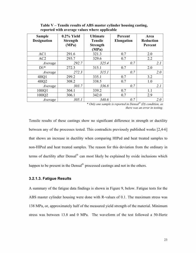
Table V – Tensile results of ABS master cylinder housing casting, reported with average values where applicable
Sample Designation
0.2% Yield Strength (MPa)
Ultimate Tensile
Strength (MPa)
Percent Elongation
Area Reduction
Percent
AC1 291.6 321.3 0.7 2.0 AC2 293.7 329.6 0.7 2.2
Average 292.7 325.4 0.7 2.1D1* 272.3 315.1 0.7 2.0
Average 272.3 315.1 0.7 2.04HQ1 299.2 335.1 0.7 3.2 4HQ2 308.2 338.5 0.7 1.0
Average 303.7 336.8 0.7 2.110HQ1 304.1 339.2 0.7 1.1 10HQ2 306.1 342.0 0.7 2.9
Average 305.1 340.6 0.7 2.0* Only one sample is reported in Densal (D) condition, as
there was an error in testing.
Tensile results of these castings show no significant difference in strength or ductility
between any of the processes tested. This contradicts previously published works [2,4-6]
that shows an increase in ductility when comparing HIPed and heat treated samples to
non-HIPed and heat treated samples. The reason for this deviation from the ordinary in
terms of ductility after Densal can most likely be explained by oxide inclusions which
happen to be present in the Densal processed castings and not in the others.
3.2.1.3. Fatigue Results
A summary of the fatigue data findings is shown in Figure 9, below. Fatigue tests for the
ABS master cylinder housing were done with R-values of 0.1. The maximum stress was
138 MPa, or, approximately half of the measured yield strength of the material. Minimum
stress was between 13.8 and 0 MPa. The waveform of the test followed a 50-Hertz

24
sinusoidal pattern. Run-out, or the quantity of cycles that if reached without failure
signaled the end of the test, was 20,000,000 cycles.
Fatigue Life as a Function of Densification Process with 95% Confidence Interval
Process Type
As-Cas
t + T6
Densa
l + T6
4HQ +
Age
10HQ +
Age
Cyc
les
to F
ailu
re
0.0
5.0e+6
1.0e+7
1.5e+7
2.0e+7
2.5e+7
Mean ValueData Points
Figure 9 – Fatigue data of ABS master cylinder housing comparing processing specifications along the abscissa to cycles to failure on the ordinate axis. Data points are summarized by a calculated mean value (shown as a hollow square) and 95% confidence interval. Fatigue testing specifications are σmax= 138 MPa, σmin= 0 MPa, 50 Hz sinusoidal waveform.
It should be noted that all the AC- and D-group samples failed during the testing,
however, several of the samples which underwent the combined processes survived the
fatigue testing. Six samples in the 4HQ group and four samples in the 10HQ group are

25
represented by their respective highest data points on Figure 8. This data is included in
the calculations to determine the confidence interval and mean value included on the
graph. The scatter inherent in the Figure 9 implies that more than just the porosity in the
samples is steering the fatigue behavior of these castings. Subsequent fractography was
necessary to further categorize the fatigue behavior.
3.2.1.4. Fractography
Optical microscopy was used to determine the point of fracture initiation on each of the
fracture samples. The results of this fractography are summarized in the graph labeled
Figure 10. Porosity was only apparent at the fracture initiation sites of un-HIPed
samples. Significant amounts of oxide inclusion at the initiation sites appeared regardless
of the processing route used in the samples. It should also be noted of Figure 10, that
even in the sample group that is shown to have porosity, the As-cast group, oxides were
the cause of some of the failures. This supports the theory of large amounts of oxide
inclusions in the castings.

26
Figure 10 – Identification of the fracture initiation types superimposed on the fatigue life graph. This graph shows that whilst porosity was a factor in the fracture initiation of the un-HIPed samples, oxides played a far more predominant role in all other process types. One fracture initiation site was deemed undetermined as porosity or oxide inclusion was identified by backscatter electron imagery.
Scanning electron microscopy was used to verify the oxide inclusions in the
fractography study. Examples of the are included as Figure 11a and 11b. Figure 11a
represents a typical pore fracture initiation site. Figure 11b shows a backscatter electron
image of an oxide inclusion at the fracture initiation site.

27
11a.
11b.
Figure 11a – SEM image of pore fracture initiation site, dendrites visible. Figure 11b - BEI image of oxide at fracture initiation site at edge of sample. Scale is shown on both micrographs
The fact that porosity was only present on the fracture surface of the un-HIPed samples
again shows that HIP improves castings by eliminating porosity. However, the abundance
of oxides on the fracture surface of the remaining samples suggests that HIP will not
improve the fatigue life of all castings. Clearly in this study the oxides played the
dominant role as the fatigue-limiting characteristic. While the lack of a difference
between the D and AC process groups would also suggest that there would be little
difference in the combined processed samples, this was not the case as there was a
significant improvement in the fatigue life of the castings subjected to a combined

28
process. This behavior has no explanation other than it seems the volume percent of the
oxide inclusions in the D and AC groups were more than those in the 4HQ and 10 HQ
groups even though the processing routes were randomly assigned to the castings. In
terms of the relative fatigue life of the combined processes compared to the traditional
individual processing route, little can be said. While it might seem that the combined
process is more capable at improving the fatigue life of castings, this must be discounted
due to the higher relative occurrence of oxides in the D process group.
3.2.2. Experimental Coupons Wedge Castings
The tensile results for the experimental coupons are show in Table VI. Labeling protocol
is identical to that describe in previous sections.
3.2.2.1. Tensile Results
Table VI – Tensile results of experimental coupons, reported with average values where applicable.
Sample Designation
0.2% Yield Strength (MPa)
Ultimate Tensile
Strength (MPa)
Percent Elongation
Area Reduction
Percent
AC2* 192.4 287.5 17.2 24.0 Average 192.4 287.5 17.2 24.0
D1 185.5 286.1 17.2 24.0 D2 188.9 288.9 17.2 23.8
Average 187.2 287.5 17.2 23.94HQ1 184.8 288.2 15.6 20.6 4HQ2 194.4 291.6 17.2 22.0
Average 189.6 289.9 16.4 21.310HQ1 196.5 295.1 17.2 21.2 10HQ2 197.2 301.3 17.2 19.2
Average 196.8 298.2 17.2 20.2* Only one sample is reported in As-Cast (AC) condition,
as there was an error in testing.

29
The tensile results for the Sr-modified A356 experimental coupons show once again no
significant variation in the tensile results as a function of processing route. It should be
noted that the level of ductility for this sample seems abnormally high by comparison to
published values [13].
3.2.3. Commercially Produced Steering Knuckle
3.2.3.1. Tensile Results
Shown below, as Table VII are the tensile results for the steering knuckle experiment.
Average values are calculated for all properties.
Table VII – Tensile results of sand-cast, Sr-modified A356 steering knuckle, reported with average values where applicable.
Sample Designation
0.2% Yield Strength (MPa)
Ultimate Tensile
Strength (MPa)
Percent Elongation
Area Reduction
Percent
AC1 * 192.0 0.3 0.4 AC2 * 217.7 0.5 0.6 AC3 * 178.6 0.3 0.2
Average * 196.1 0.4 0.4D1 248.9 274.0 1.3 1.8 D2 250.6 263.9 0.7 1.2 D3 249.6 266.9 0.9 0.6
Average 249.7 268.3 1.0 1.24HQ1 210.9 241.0 1.2 2.6 4HQ2 225.1 252.3 1.2 2.6 4HQ3 212.8 243.2 1.5 2.0
Average 216.3 245.5 1.3 2.410HQ1 223.3 252.7 1.3 1.8 10HQ2 204.8 250.2 2.0 2.6 10HQ3 212.5 250.3 2.0 2.3
Average 213.5 251.1 1.8 2.2* Yield strength in As-Cast (AC) condition, were deemed
erroneous by testing facility and hence not reported.

30
As with the two previous studies the difference in the strength and ductility for these
castings as a function of the processing route in negligible. It should be noted in this case
that the ductility of all these samples is notably lower than the published standards [13].
Furthermore, the AC process group, which was commercially heat treated displays the
lowest values of ductility.
3.2.3.2. Fatigue Results
The fatigue results for these samples are shown as Figure 12. The testing specifications
used for this round of testing allowed the results to be presented in S-N form. The data
are presented in this manner because the amount of samples allowed for fatigue testing
with various stress levels. The two previous studies were done with significantly fewer
sample castings. Stress level is noted on the graph. The waveform of the testing was 50
Hertz sinusoidal with an R-ratio of -1.0.

31
Fatigue Life as a Function of Processing Route
Cycles to Failure
1e+2
1e+3
1e+4
1e+5
1e+6
1e+7
1e+8St
ress
Lev
el (M
Pa)
80
100
120
140
160
180
200
220
As Cast + T6Densal + T6Combined, 4HQCombined, 9HQ
Figure 12 – Fatigue data of sand-cast Sr-modified A356 steering knuckles. Data is presented in S-N format. Test frequency was 50 Hertz. R-ratio for tests equals –1.0.
This round of testing conforms more regularly with previously held beliefs on the effect
of HIP on the fatigue properties of aluminum castings. It should be noted that there is an
order of magnitude increase in fatigue life of the HIPed samples (both those which were
independently processed, and those subjected to the combined process) at the lower stress
levels (~115MPa). There is much less difference as the stress level approaches the yield
strength of the alloy (~210 MPa) which is to be expected. It would also seem that the
variance in the HIPed samples is much smaller than the variance in the un-HIPed

32
samples. Furthermore there is no appreciable difference between the fatigue performance
of the samples that were traditionally densified and heat treated and those that were
processed with the combined methodology.
4. Conclusions
4.1. Process Combination Feasibility
Clearly the possibility of continuing on to the mechanical property evaluation portion of
this experiment depended on the successful implementation of the experimental
procedure. It was shown experimentally in this study that maintaining solutionizing
temperature during the venting portion of the HIP cycle is possible. Furthermore, it is
likely that the energy required to maintain Tsolution during depressurization is proportional
to the amount of gas in the vessel due to the adiabatic expansion of the gas. This would
mean that as the load size increases the power required to maintain temperature is
reduced. Hence, this experiment, with only one casting processed, actually used the most
power and as the casting load increases to the capacity of the vessel, maintaining Tsolution
will likely become easier.
The measured quench delay for the experimental process also proved short enough for
the continued process evaluation.
4.2. Mechanical Property Evaluation
• Tensile results of all the experiments conducted prove that the combined
Densal/solution heat treat process produces casting with similar tensile properties to
castings processed with the standard methods. This proves that elevated pressure has

33
no detrimental effect on the tensile properties of the castings tested here. In terms of
resultant tensile properties, a combined Densal/solution heat treat process is feasible.
• Fatigue results in the study of the ABS master cylinder housing prove that oxide
inclusions can play a major role in crack initiation. In comparison to previous
research the presence of oxides in the samples appear to mask the beneficial effect of
HIP densification [2,4-6]. However, the fatigue data of both combined processes
seem to mirror previously held theories of the effect of HIP on the fatigue life of
castings. Both of the combined Densal® + solution heat treating processes yielded
fatigue properties that were significantly better than those of as-cast + T6 samples.
Also, in the scope of this experimental run, savings in both process time and energy
were realized by combining the processes.
• In viewing the fatigue results of the sand-cast, Sr-modified A356 steering knuckle, an
improvement in fatigue strength after Densal is readily apparent when compared to
non-HIPed samples. Therefore, it is possible to make a direct comparison between the
combined processes and the standard methods in the production of critical application
aluminum castings. It is therefore concluded, that the parts subjected to the combined
process show no appreciable difference in fatigue strength when compared to parts
produced by the standard Densal + T6 process. Saving in both time and energy over
the traditional methods were incurred by using the combined process. These results
warrant further investigation into the implementation of a commercial combined
Densal/solution heat treat process.

34
5. References
[1]. C.R. Brooks, ASM Handbook, vol. 4, ASM International, Materials Park, OH, 1991, pp. 823-879.
[2]. Q.G. Wang, D. Apelian, D.A. Lados, Fatigue Behavior of A356-T6 Aluminum Cast Alloys. Part I. Effect of Casting Defects, Journal of Light Metals 1, 2001, pp. 73-84.
[3]. T.L Reinhart, ASM Handbook, vol. 19, ASM International, Materials Park, OH, 1996, pp. 813-822.
[4]. J.C. Hebeisen, B.M. Cox, J. Turonek, R. Stack, The Effect of Densal Processing on the Properties of a Cast Aluminum Steering Knuckle, SAE Technical Publication, 2002.
[5]. C.S.C Lei, W.E. Frazier, E.W. Lee, The Effect of Hot Isostatic Pressing on Cast Aluminum, Journal Of Metals, November 1997, pp. 38-39.
[6]. S.J. Mashl, J.C. Hebeisen, D. Apelian, Q.G. Wang, Hot Isostatic Pressing of A356 and 380/383 Aluminum Alloys: An Evaluation of Porosity, Fatigue Properties and Processing Costs, SAE Technical Publication #2000-01-0062.
[7]. D. Apelian, S. Shivkumar, S. Sigworth, Fundamental Aspects of Heat Treatment of Cast Al-Si-Mg Alloys, American Foundrymen’s Society Transactions, vol. 89, No. 137, pp. 727-742.
[8]. S, Shivkumar, C. Keller, D. Apelian, Aging Behavior in Cast Al-Si-Mg Alloys, American Foundrymen’s Society Transactions, Vol. 90, No. 179, pp. 905-911.
[9]. H.J. Li, S. Shivkumar, D. Apelian, Influence of Modification on the Solution Heat-treatment Response of Cast Al-Si-Mg Alloys, Cast Metals, Vol. 1, No. 4, 1990, pp. 227-234.
[10]. H.V. Atkinson, S. Davies, Fundamental Aspects of Hot Isostatic Pressing: An Overview, Metallurgical and Materials Transactions A, Vol. 31A, December 2000, pp. 2981-3000.
[11]. H.V. Atkinson, B.A. Rickinson, Hot Isostatic Processing, Adam Hilger, Bristol, UK, 1991.
[12]. C, Bergmann, HIP Quenching in 2000 Bar Argon Gas, Metal Powder Report, October 1990, pp. 669-671.
[13]. A.L. Kearney, ASM Handbook, vol. 2, ASM International, Materials Park, OH, 1990, pp. 152-169.

Theoretical modeling of energy savings incurred from the use of a combined Densal/solution heat treatment for cast
aluminum alloys
Matthew M. Diem Bodycote IMT, Inc.
WPI
Stephen J. Mashl Bodycote IMT, Inc.
Richard D. Sisson WPI

36
Abstract
Previous work by the authors has shown that the combined process of HIP/Densal and
solution heat treatment effectively mimics the microstructure and mechanical properties
of the current, individual processes of HIP/Densal and subsequent solution heat
treatment. This paper evaluates the energy consumption of the combined process and the
two independent processes. Thermodynamic calculations revealed that the energy
consumed by the combined process for a typically loaded HIP vessel is fifty percent less
than the energy required to process the same quantity of castings with the two individual
processes. However, it was determined that a critical ratio of the volume occupied in the
HIP vessel by castings to the total HIP vessel volume exists that ultimately determines
the efficiency of the combined process. This critical ratio was calculated to be
approximately fifteen percent. If the volume ratio is less than fifteen percent then the
combined process is less energy efficient then conventional processing. These
thermodynamic calculations were experimentally verified with power consumption
process data in a production facility. In addition, the time required for the combined
process of HIP/Densal and solution heat treatment was thirty percent less than the
conventional two-step process.
1. Introduction
Hot isostatic pressing (HIP) is used in industry to eliminate porosity in castings [1,2].
HIP uses elevated temperature and pressure to hydrostatically compress castings and
eliminate pores through plastic deformation and diffusional creep mechanisms [1-2]. The
elimination of porosity in castings leads to increased fatigue life, ductility and impact

37
toughness [3-7]. While the advantages of using the HIP process are clear, it is still an
independent process that adds time and energy costs to the production of critical
application castings. The first step in the cost reduction of the HIP process for aluminum
castings was the Densal process. Densal is a Bodycote proprietary densification
process tailored specifically for the elimination of porosity in critical applications
aluminum castings [6]. It is speculated that further time and energy savings could be
realized through additional integration of the Densal process into the manufacturing
procedure of aluminum castings.
One method of integrating Densal into the manufacturing process is to combine it with
the subsequent heat treating steps that are necessary to attain desired tensile properties. A
typical T6 heat treatment of A356 aluminum, according to ASM [8] includes an 8-12
hour solutionizing soak at 540°C to homogenize the alloy and create a saturated solid
solution of the alloying constituents. Next, to form a supersaturation of the alloying
constituents, a rapid quench is employed. Finally, an aging step of 3-5 hours at 155°C is
used to obtain optimal tensile properties [8-10]. Due to similarities in the solutionizing
temperature of most aluminum alloys and the dwell temperature of the Densal process, a
process combination is appropriate. Experimental work completed by the author shows
that a combined process is viable in terms of the resultant mechanical properties of the
castings tested. In fact, the work completed shows no difference between the tensile and
fatigue properties of the castings processed by the combined Densal/solution heat
treatment process or the independent Densal and solution heat treatment processes [7].
Shown as Figure 1 are S-N data points comparing the fatigue behavior of castings
subjected to combined Densal/solution heat processes, and castings subjected

38
independent Densal and heat treatment. The fatigue behavior of castings that were not
subjected to a HIP process is also included in the graph. The difference between the
castings subjected to either of the combined processes and the independent process is
negligible. It should be noted that the difference in fatigue life between the un-HIPed
samples and the HIPed samples is nearly an order of magnitude in the most extreme
cases.

39
Fatigue Life as a Function of Processing Route
Cycles to Failure
1e+2
1e+3
1e+4
1e+5
1e+6
1e+7
1e+8St
ress
Lev
el (M
Pa)
80
100
120
140
160
180
200
220
As Cast + T6Densal + T6Combined, 4HQCombined, 9HQ
Figure 1 – Verification of fatigue results from previous study. Graph shows no difference in fatigue behavior between castings subjected to the independent processes of Densal followed by T6 heat treatment (labeled “Densal + T6”) and castings subjected to the combined process of Densal/solution heat treatment followed by aging (“Combined, 4HQ” and “Combined, 9HQ”). It should be noted that there is a marked improvement in the fatigue behavior of all the densified samples compared to the un-HIPed samples (“As Cast + T6”). The two different combined processes, 4HQ and 9HQ, are different from each other in the length of time spent at solution temperature, which were four hours and nine hours, respectively.
The thermal profile of the combined process is shown in comparison to the thermal
profile of the two independent processes as Figure 2. The profiles show the basic premise

40
behind the process combination: The combined process uses the time spent at HIP dwell
temperature as part of the solutionizing dwell time. The castings are then water quenched
from the HIP vessel. More details on the design of the experimental process can be seen
in citation [7]. Figure 2 also shows the time savings incurred by the use of the combined
process. It is estimated that the time from mold to service for the combined process is
seventy percent of the time required for the independent processes.
Thermal Profile of Processes
Time
Temperature Independent solution dwell and quench
Age
Independent HIP Dwell
Combined HIP and solution heat treat dwell and quench
Age
Figure 2 – Thermal profiles of experimental samples subjected to the combined Densal/ solution heat treat process (foreground) the independent processes of Densal and T6 treatment (background). This graph shows significant time savings by using the combined process. It indicate that the combined process is completed approximately 30% quicker than the independent processes assuming no time between the end of Densal process and the start of the solution heat treatment for the castings produced with the conventional independent process. Units are omitted from the graph to preserve Bodycote PLC proprietary specifications.
41
The purpose of this paper is to present the theoretical work done in modeling the energy
consumption of the combined Densal/solution heat treatment process. These data
calculations will be compared to the energy consumption of the conventional,
independent processes. Experimental data will be used to verify the results of the
theoretical modeling.
2. Procedure
2.1. Theoretical Framework
2.1.1. Identification of Energy Consumption
In order to compare the energy consumption of the two processing routes being
examined, it is necessary to first understand all the thermal and mechanical energies
involved with the processes. This will be accomplished by modeling castings and where
appropriate, their surrounding gas media, as a thermodynamic system. This system will
be examined as it passes through the different process routes.
Let the heat transferred into the system be defined as Q, and the mechanical work done
by the pressurizing media in the system be defined as W. If, for example, the gaseous
media is allowed to expand and depressurize, the system does negative work, conversely,
if the gas is compressed, positive work is done.
Conventional processing starts with the HIP cycle, which heats and pressurizes the
system, +Q and +W. Heat is constantly added into the system via furnace power during
the tenure of the HIP dwell portion due to energy losses into the HIP vessel walls, etc. but
the pressure is not subject to much change as little of the mechanical energy is lost. After

42
the dwell portion of the HIP cycle, the pressurized gas is vented and the system is cooled,
-Q, and -W. The heat treatment cycle commences with the application of thermal energy,
+Q, to the system until the solutionizing temperature, Tsolution, is reached. Tsolution is
maintained for a given time and the heat is rapidly removed from the system via a water
quench, -Q. The energy transfer in the aging step mimics that of the solution step less the
quench, i.e. gradual heat gain, +Q, followed by gradual heat loss, -Q.
In the combined process, again thermal and mechanical energies are added to the system
at the start of the HIP cycle. During the depressurization step, expanding gas again
performs negative work on the system (-W), which, if left unabated would lead to cooling
within the system via adiabatic expansion of the gas. To overcome this, heat is added to
the system to maintain Tsolution (+Q). This heat remains in the system until the quench
step. The other steps in the process are identical to those described above.
This relationship between temperature, pressure and thermal and mechanical energies are
shown schematically for the individual processing method as Figure 3. Figure 4 shows
the same relationship for the combined process. These graphs are a simplification of the
actual heating processes as heat is lost from the system continuously and therefore
requires constant minute energy adjustments to maintain both HIP and solutionizing
dwell temperatures. It is however assumed that these adjustments will be roughly
equivalent between both the combined process and the individual process methods of
production and therefore these adjustments are ignored.

43
Figure 3 – Schematic detail of the energy consumed by the individual processes of Densal and solution heat treatment (the aging process is not shown on this graph). The top portion of the graph shows the thermal profile of a casting subjected to the individual processes, temperature versus time. The bottom portion shows the corresponding thermal energy requirements (solid line) as well as the mechanical work done on the system (dashed line). The boxed area represents the area of interest in terms of the thermal energy comparison to the combined process.

44
Figure 4 – Schematic detail of the energy consumed by the combined Densal/solution heat treatment. The top portion of the graph shows the thermal profile of a casting subjected to the combined process, temperature versus time. The bottom portion shows the corresponding thermal (solid line) and mechanical (dashed line) energy requirements. The boxed area represents the region of interest in the thermal modeling. The curves included in the boxed area represent the thermal energy (solid) required to overcome the adiabatic cooling work (dashed) done by the gas on the system.
It should be noted of the bottom portions of Figures 3 and 4, that any line below the
abscissa represents a negative energy. Therefore the negative work done by the
depressurization is shown below this axis, as is the thermal energy removed from the
system during the quench.
If all the steps that are identical in the two processing routes are discounted, it becomes
clear that there are only two necessary comparison points to determine the difference in
process efficiency. The heat up portion of the solution heat treatment in the individual
processes, and the temperature maintenance step during the depressurization of the

45
combined process are all that need to be compared. These portions are shown as the
boxed in area in Figures 3 and 4.
2.1.2. Calculations
2.1.2.1. Individual Process Calculations
To calculate the amount of energy required to raise a casting from room temperature,
Tambient, to solution temperature, Tsolution, as would be the case when solution heat treating
a casting in the conventional independent process, requires using the following formula:
TmcE p∆= [eq. 1]
Where, E is the total energy required to raise the system of a casting being modeled with
mass m, and specific heat cp, from Tambient to Tsolution, represented as ∆T.
2.1.2.2. Combined Processes Calculations
Pressurized gas in the HIP vessel complicates the modeling of the energy requirements
for the combined process, as it adds another component to the thermodynamic system
that cannot be neglected. This is because gas undergoing pressure changes does work on
the casting in the system. Fortunately, experiments completed to date [7] have shown that
there is no difference in the temperature of the gaseous pressurizing media in the HIP
vessel and the castings that are in contact with the gas. This is a due to the high heat
transfer rate between the castings and the gas that results from the elevated pressure in
the HIP vessel. The heat transfer coefficient between the castings and the gas at the
pressures involved in this process is on the order of 100 W/m2 K [11]. Therefore it can be
stated correctly that the temperature of the gas and the castings within a HIP cycle are

46
identical. Furthermore, it is reasonable to assume all that is required to calculate the
energy needed to maintain Tsolution in the casting is to calculate the energy required to
maintain Tsolution in the gas. The governing equation for the system being modeled in the
HIP vessel is the First Law of Thermodynamics, which states:
WuuQ +−= 12 [eq. 2]
Where, Q, represents the amount of heat transferred into the system to maintain Tsolution,
u1 and u2 represent the internal energy of the gas at maximum and minimum pressure,
respectively, and W, represents the work done by the expanding gas as pressure is vented.
By design, this system is isothermal, that is, during the depressurization of the HIP
vessel, heat is added to maintain Tsolution and consequently there is no change in
temperature. Internal energy of any gas is only a function of temperature, therefore it can
be concluded that there is no change between u1 and u2, and therefore equation 2 is
simplified to:
WQ = [eq. 3]
This basically states that the heat required to maintain Tsolution is equal in magnitude to the
work done by the expanding gas. In the case of an ideal gas, this value is a relatively
simple computation of:
∫−=2
1
v
v
PdvW
[eq. 4]
Where v1,v2 are the specific volumes of the gas at maximum and minimum pressure
respectively, and P is the starting pressure of the nitrogen gas. When combined with
Boyle’s law of ideal gases, Equation 4 takes on the form:

47
mvvTR
vdvTRW
v
v 1
2ln2
1
−=−= ∫ [eq. 5]
Where R represents the gas constant of nitrogen (universal gas constant divided by the
molecular weight of nitrogen), T represents the isothermal temperature, and m is the mass
of the gas involved. Equation 5 will be used to determine the amount of energy required
to maintain Tsolution. This value will be directly compared to the energy requirement
calculated for the solution heat treatment step for the individual processes.
The major assumption made in these calculations is that the temperature within the HIP
vessel is uniform during the venting process.
2.2. Experimental Verification of Modeling
A casting subjected to a combined HIP/solution heat treat process was instrumented with
Type-K thermocouples in order to verify the theoretical calculations of process energy
consumption. The casting chosen for this test was a commercially produced, permanent
mold, Al-Si-Mg automotive ABS master cylinder housing. This casting is approximately
1kg in mass and 150mm by 150mm by 30mm in dimensions with a relatively high
surface area-to-volume ratio. The purpose of choosing a casting with a high surface area-
to-volume ratio was that this casting represents a “worst case scenario” of retaining heat
during depressurization. The chemical composition of the ABS master cylinder housing,
determined through Inductively Coupled Plasma-Atomic Emission Spectroscopy (ICP-
AES), is given in Table I.

48
Table I - Chemical composition of Al-Si-Mg ABS master cylinder housing casting determined via ICP-AES. Values are the averages of five readings performed on two different castings (ten total readings). The standard deviations for the calculations are included to show statistical variance in data.
Si Mg Fe Ti Sr Cu, Mn, Ni, Zn
Average Weight % 6.77 0.88 0.14 0.099 0.009 <0.035
Standard Deviation 0.118 0.022 <0.005 <0.003 0.000 <0.005
To show the relative complexity of the casting used, a sectioned view is included as
Figure 5 below. Two thermocouples were used to record the thermal profile of the casting
in the initial experiments and their location in the part is shown in Figure 5. The location
of one thermocouple (TC) is marked in the three views with an “+”. This TC measured
the center temperature of the casting. The second TC, which is marked with an “o” in the
figure, records the “skin” temperature of the casting.

49
Figure 5 – Sectioned ABS master cylinder housing used in initial experiments. Location of two thermocouples marked in all views with + and o. (12-inch rule included to show scale)
The HIP vessel used was an ABB model at Bodycote IMT, Inc., in Princeton, KY. The
working height and diameter of the HIP vessel are respectively 305mm and 205mm.
Nitrogen gas was used as the HIP media. Type-K TCs were used to instrument the
castings. Readings of temperature, pressure and furnace power were logged every two-
minutes. Time, temperature and pressure of the run followed the Densal proprietary
specifications. For this study, the maximum gas vent rate that allowed the casting skin
temperature to remain above Tsolution was used. The pressure vent rate used was
calculated as approximately 0.5 MPa/minute.

50
3. Discussion and Results
3.1. Theoretical Modeling
The physical and thermal properties of the casting modeled are shown in Table II. The
amount of energy required to raise the temperature of a casting from Tambient to Tsolution for
these parameters as well as the amount of energy required to maintain Tsolution in the
combined process are also shown in Table II.
Table II – Physical and thermal properties of single casting modeled. Calculated energy requirements of attaining Tsolution during heat treatment as well as energy required to maintain Tsolution during combined process venting are shown in bold.
Property Value Property Units Mass of casting 1.00 Kg Specific heat of casting ~900 J/kg-K Tsolution – Tambient, ∆T 475 K
Energy elevate casting to Tsolution during heat
treatment
~430 kJ
Volume of HIP vessel 0.01 m3
Total volume of casting 0.0004 m3 Gas constant for N2, R 296804.39 J/kg-K Maximum gas pressure, P1 35.0 MPa Minimum gas pressure, P2 0.1 MPa Specific volume of N2 at P1 6.55 m3/kg Specific volume of N2 at P2 2294.29 m3/kg Mass of N2 at P1 0.0015 Kg
Energy required to maintain Tsolution during
combined process
~2000 kJ
It is clear from this fundamental calculation that the combined process is actually less
efficient in terms of energy consumption than the independent processes. This appears to
contradict intuition, as it would seem that the combined process would be the more
efficient process. However, the ability of the HIP vessel to maintain Tsolution during

51
venting relies on the fact that the vessel is nearly completely occupied, not by the
pressurized gas, but by the castings being processed. In this calculation, the ratio of the
volume occupied by the casting to the overall HIP vessel volume is quite low. If the same
calculations are done with a higher percentage of the HIP vessel volume consumed by the
castings the figures are quite different. This data is shown in Table III below.
Table III – Physical and thermal properties of multiple castings modeled. Calculated energy requirements of attaining Tsolution during heat treatment as well as energy required to maintain Tsolution during combined process venting for seven castings are again show in bold.
Property Value Property Units Mass of casting 7.00 Kg Specific heat of casting ~900 J/kg-K Tsolution – Tambient, ∆T 475 K
Energy elevate casting to Tsolution during heat
treatment
~2800 kJ
Volume of HIP vessel 0.01 m3
Total volume of casting 0.0028 m3 Gas constant for N2, R 296804.39 J/kg-K Maximum gas pressure, P1 35.0 MPa Minimum gas pressure, P2 0.1 MPa Specific volume of N2 at P1 6.55 m3/kg Specific volume of N2 at P2 2294.29 m3/kg Mass of N2 at P1 0.0011 Kg
Energy required to maintain Tsolution during
combined process
~1500
kJ
Clearly, it can be concluded that the volume percent of the HIP vessel that is occupied by
castings has a significant impact on the efficiency of the combined process. Figure 6,
further illustrates this point. This graph shows the relationship between the number of
castings being processes and the theoretical energy required to complete the specified
process.

52
Theoretical energy consumed by the different processing routes as a function of the quantity of castings being modeled
0.0
500.0
1000.0
1500.0
2000.0
2500.0
3000.0
3500.0
0 1 2 3 4 5 6 7 8
Number of Castings Being Modeled
Ener
gy U
sage
(kJ)
Combined ProcessIndividua Process
Figure 6 – Theoretical energy required to maintain Tsolution in the combined process, and attain Tsolution in the conventional process as a function of the quantity of castings being modeled. This graph clearly shows the amount of energy consumed by the maintenance of Tsolution in the combined process is inversely related to the amount of castings processed.
Therefore, a ratio of casting volume to HIP vessel volume exists that defines the level of
efficiency that is attainable through the combined process. The same graph in Figure 6 is
presented as Figure 7 with the abscissa showing the volume percentage of the HIP vessel
occupied by castings. Figure 7 shows that for a given HIP vessel a minimum level of
castings must be determined to use the combined process in an energy efficient manner.
For this example, calculations indicate that the value of this “efficiency ratio” equals
approximately fifteen percent.

53
Theoretical energy consumed by the different processing routes as a function of the percentage of HIP vessel volume occupied by castings
0.0
500.0
1000.0
1500.0
2000.0
2500.0
3000.0
3500.0
0.00 5.00 10.00 15.00 20.00 25.00 30.00
Volume of HIP Vessel Occupied by Castings
Ener
gy U
sage
(kJ)
Combined ProcessIndividua Process
Figure 7 – Theoretical energy required to maintain Tsolution in the combined process, and attain Tsolution in the conventional process as a function of the volume percent of the castings being modeled over the total HIP volume. The quantity of castings required to attain a greater energy efficiency in the combined process versus the individual process is the quantity of castings that equals greater then fifteen percent of the HIP vessel volume, i.e. five castings.
Therefore, in order for a combined process to be more energy efficient than the individual
processes, the HIP vessel must be at least fifteen percent occupied by castings. For
comparison, if only one casting is processed in the vessel as was originally calculated, the
casting volume-to HIP vessel volume ratio is 0.04, or four percent of the vessel is
occupied by the casting.
According to the calculations done here it has been showed that a combined process done
with a “fully loaded” HIP vessel can be nearly twice as energy efficient as the

54
independent cycle. Conversely the process can also be half as energy efficient in the case
of a “under loaded” vessel.
3.2. Experimental Verification
Figure 8 shows a graph of casting temperature, gas pressure and HIP furnace power as a
function of time for the combined HIP/solution heat treat run. As was proven in the
theoretical calculations previously reported, the graph shows the impact of venting at
constant temperature on furnace power as a significant increase in the power requirement
to maintain Tsolution during depressurization. Note that the power peak during the pressure
venting process consumes more energy, i.e. contains more area beneath it, than the initial
ramp up portion of the cycle.

55
Temperature, furnace power and pressure as a function of time for one casting
0
500
1000
1500
0 122242
Time (minutes)
Tem
pera
ture
(C),
Pow
er (W
atts
)
0.00
10.00
20.00
30.00
40.00
50.00
Pres
sure
(MPa
)
T_skin
Furnace Power
Gas Pressure
Figure 8 – Graph showing the relationship between pressure and furnace power as casting temperature remains constant during venting. Pressure vent rate is roughly constant (~0.5MPa/minute). HIP vessel contains one instrumented casting (mass=~1 kg). It should be noted that T_skin, shown near the bottom of the graph as a solid line, is maintained during the depressurization step, but this maintenance is at the significant cost of furnace power (represented by the line marked with diamond symbols).

56
Temperature, furnace power and pressure as a function of time for seven castings
0
500
1000
1500
2000
2500
0 124234
Time (minutes)
Tem
pera
ture
(C),
Pow
er (w
atts
)
0.00
10.00
20.00
30.00
40.00
50.00
Pres
sure
(MPa
)
Furnace PowerT_skinGas Pressure
Figure 9 – Graph showing the relationship between HIP pressure and furnace power as casting temperature remains constant during venting. Pressure vent rate is roughly constant (~0.5MPa/minute). HIP vessel contains one instrumented casting and six sample castings (total mass = ~7 kg). As is expected, the overall power consumed by the process is more than that in the previous example. T_skin, shown as the thick line near the bottom of the graph, is again maintained during the depressurization step and the amount of energy needed to maintain this temperature during venting is comparatively small.
Figure 9 presents a graph of constant temperature venting with a load in the HIP vessel of
seven castings (one instrumented casting and casting six castings being processed). This
data demonstrates that because the aluminum castings occupy more of the vessel volume
(~4% versus ~28%), and consequently less gas is present, the impact of venting at
constant temperature on furnace power is significantly decreased by comparison to the
previous data. Compared to the initial heat-up portion of this cycle, the second power
peak, which occurs during the pressure-venting portion of the cycle, is relatively low.

57
This experimental data supports the theoretical modeling conclusion that process energy
efficiency increases with the volume occupied by castings in the HIP vessel.
4. Conclusions
The combined process of Densal and solution heat treatment has the potential for
saving as much as thirty-percent in process time when compared to the independent
processes. This figure does not however take into account the transit time between
HIP and heat treatment facilities that most castings that are currently HIPed are
subjected to. If this time is incorporated into the calculations even greater savings in
mold-to-service times could be expected.
It has been proven that the combined process is not always more energy efficient than
the alternative independent Densal and solution heat treat processes. In fact a ratio
of casting volume being processed-to-HIP vessel volume exists that determines
whether or not the combined process is more energy efficient than the independent
processes. If the volume of castings within the vessel is sufficiently in comparison to
the total HIP vessel volume small (less than fifteen percent), the energy required to
overcome the cooling which results from the adiabatic gas expansion makes the
combined process less energy efficient than the independent process.
However, the desire to achieve maximum process efficiency dictates that most HIP
cycles are run at full vessel capacity, so the likelihood of a partially loaded HIP vessel
can be discounted. In the worse case scenario of loading the HIP vessel to maximize
subsequent quench rates, the casting volume-to-vessel volume would still be
sufficiently high to ensure energy savings [8]. Therefore, allowing that the volume

58
percent of castings in the HIP vessel will always be greater than the threshold value
suggested herein, the combined process, even conservatively estimated could increase
energy efficiency of the densification/heat treat portion of the production of critical
application aluminum castings by as much as fifty percent.
5. References
[1]. H.V. Atkinson, S. Davies, Fundamental Aspects of Hot Isostatic Pressing: An Overview, Metallurgical and Materials Transactions A, Vol. 31A, December 2000, pp. 2981-3000.
[2]. H.V. Atkinson, B.A. Rickinson, Hot Isostatic Processing, Adam Hilger, Bristol, UK, 1991.
[3]. Q.G. Wang, D. Apelian, D.A. Lados, Fatigue Behavior of A356-T6 Aluminum Cast Alloys. Part I. Effect of Casting Defects, Journal of Light Metals 1, 2001, pp. 73-84.
[4]. C.S.C Lei, W.E. Frazier, E.W. Lee, The Effect of Hot Isostatic Pressing on Cast Aluminum, Journal Of Metals, November 1997, pp. 38-39.
[5]. J.C. Hebeisen, B.M. Cox, J. Turonek, R. Stack, The Effect of Densal Processing on the Properties of a Cast Aluminum Steering Knuckle, SAE Technical Publication, 2002.
[6]. S.J. Mashl, J.C. Hebeisen, D. Apelian, Q.G. Wang, Hot Isostatic Pressing of A356 and 380/383 Aluminum Alloys: An Evaluation of Porosity, Fatigue Properties and Processing Costs, SAE Technical Publication #2000-01-0062.
[7]. M.M. Diem, S. Mashl, R. Sisson, Cost Effective Densification of Critical Application Aluminum through Simultaneous Densal and Solution Heat Treatment. Part 1 Testing Industrial Castings, TBA.
[8]. C.R. Brooks, ASM Handbook, vol. 4, ASM International, Materials Park, OH, 1991, pp. 823-879.
[9]. S, Shivkumar, C. Keller, D. Apelian, Aging Behavior in Cast Al-Si-Mg Alloys, American Foundrymen’s Society Transactions, Vol. 90, No. 179, pp. 905-911.
[10]. D. Apelian, S. Shivkumar, S. Sigworth, Fundamental Aspects of Heat Treatment of Cast Al-Si-Mg Alloys, American Foundrymen’s Society Transactions, vol. 89, No. 137, pp. 727-742.
[11]. C, Bergmann, HIP Quenching in 2000 Bar Argon Gas, Metal Powder Report, October 1990, pp. 669-671.
[12]. F.T. Wall, Chemical Thermodynamics,W. H. Freeman and Company, San Francisco , CA, 1958.

59
[13]. A.F. Mills, Heat and Mass Transfer, Irwin, Chicago, IL, 1995.
[14]. E.G. Cravalho, J.L. Smith Jr., Thermodynamics (An Introduction), Holt, Rinehart and Winston, Inc., New York, NY, 1971.

60
5. Conclusions
• Tensile results of all the experiments conducted prove that the combined
Densal/solution heat treat process produces casting with similar tensile properties to
castings processed with the standard methods. This proves that elevated pressure has
no detrimental effect on the tensile properties of the castings tested here. In terms of
resultant tensile properties, a combined Densal/solution heat treat process is feasible.
• Fatigue results in the study of the ABS master cylinder housing prove that oxide
inclusions can play a major role in crack initiation. In comparison to previous
research the presence of oxides in the samples appear to mask the beneficial effect of
HIP densification. However, the fatigue data of both combined processes seem to
mirror previously held theories of the effect of HIP on the fatigue life of castings.
Both of the combined Densal® + solution heat treating processes yielded fatigue
properties that were significantly better than those of as-cast + T6 samples. Also, in
the scope of this experimental run, savings in both process time and energy were
realized by combining the processes.
• In viewing the fatigue results of the sand-cast, Sr-modified A356 steering knuckle, an
improvement in fatigue strength after Densal is readily apparent when compared to
non-HIPed samples. Therefore, it is possible to make a direct comparison between the
combined processes and the standard methods in the production of critical application
aluminum castings. It is therefore concluded, that the parts subjected to the combined
process show no appreciable difference in fatigue strength when compared to parts
produced by the standard Densal + T6 process. Saving in both time and energy over
the traditional methods were incurred by using the combined process.

61
Modeling the time expense proves that the combined process of Densal and solution
heat treatment has the potential for saving as much as thirty-percent in process time
when compared to the independent processes. This figure does not however take into
account the transit time between HIP and heat treatment facilities that most castings
that are currently HIPed are subjected to. If this time is incorporated into the
calculations even greater savings in mold-to-service times could be expected.
Theoretical modeling has also proven that the combined process is not always more
energy efficient than the alternative independent Densal and solution heat treat
processes. In fact an approximate ratio of casting volume being processed-to-HIP
vessel volume doing the processing exists that determines whether or not the
combined process is more energy efficient than the independent processes. If the
volume of castings within the vessel is sufficiently small in comparison to the total
HIP vessel volume, the energy required to overcome the cooling which results from
the adiabatic gas expansion makes the combined process less energy efficient than the
independent process.
However, the desire to achieve maximum process efficiency dictates that most full
runs are run at the HIP vessel capacity, so the likelihood of a partially loaded HIP
vessel can be discounted. In the worse case scenario of loading the HIP vessel to
maximize subsequent quench rates, the casting volume-to-vessel volume would still
be sufficiently high to ensure energy savings. Therefore, allowing that the volume
percent of castings in the HIP vessel will always be greater than the threshold value
suggested herein, the combined process, even conservatively estimated could increase

62
energy efficiency of the densification/heat treat portion of the production of critical
application aluminum castings by as much as fifty percent.
These results warrant further investigation into the implementation of a commercial
combined Densal/solution heat treat process.
![Isostatic Pressing - PickPM · About Isostatic Pressing?]The fluid pressure acts uniformly in all directions. ... Advantages of HIP PM]Fine structure, isotropic properties]](https://img.pdfslide.us/doc/110x75/5b30fc137f8b9ae1108b5935/isostatic-pressing-pickpm-about-isostatic-pressingthe-fluid-pressure-acts.jpg)