Embed Size (px)
Citation preview

Acta Chemica Malaysia (ACMY)2(2) (2018) 29-44
Cite The Article: Akram Tawari, Bashir Brika, SM Bradshaw, EP Jacobs (2018). Development Of A Cellulose Acetate Hollow-Fine-Fibre Membrane. Acta Checmica Malaysia, 2(2):29-44.
ISSN: 2576-6732 (Print) ISSN: 2576-6724 (Online) CODEN: ACMCCG
ARTICLE DETAILS
Article History:
Received 4 January 2019 Accepted 7 February 2019 Available online 20 March 2019
ABSTRACT
The goal of this study is to produce cellulose acetate (CA) hollow-fine-fibre membranes with good water flux
performance in the 95 – 96% salt retention range for brackish water desalination. A dry-wet spinning technique was used for the preparation of the hollow-fine-fibre membranes. Hollow-fine fibres were spun using CA dissolved in a
suitable solvent and non-solvent mixture comprising acetone and formamide. The effects of the dope composition and
spinning parameters such as solvent to non-solvent ratio, bore fluid ratio, take-up speed, dope extrusion rate and heat treatment on the membrane morphology and performance were investigated. The elimination of macrovoids from
the morphology of hollow-fine-fibre membranes was achieved in two ways. Firstly, increasing the formamide ratio in
the polymer solution and secondly, decreasing the water activity in the bore fluid by adding a solvent (acetone) to
water. The mechanical strength of the fibres increased with increasing take-up speeds. This could be attributed to the
higher orientation caused by higher take-up speeds. CA hollow-fine-fibre membrane showed good salt retention at an annealing temperature of 86 °C and annealing period of two subsequent times. The developed hollow-fine-fibre
membranes showed a good brackish water desalination performance within brackish water operating conditions.
KEYWORDS
Reverse osmosis membrane, hollow-fine fibre membrane, cellulose acetate, spinning parameters, membrane
morphology
1. INTRODUCTION
About 60% of the land surface of the earth is arid, and most of this dry
portion of the earth’s surface is near to or has available sources of saline
water. These arid regions in the world, including North Africa, Arabian
Gulf and Middle East, are actively searching for supplementary sources of fresh water to help fulfilling future demands. This quest includes new
sources of fresh water such as the desalination of brackish and seawater. According to the World Health Organization drinking water should not contain more than 500 ppm dissolved salts and water containing more
than 1000 ppm should not be used for human consumption [1]. Water containing 1000 – 5000 ppm dissolved solids is classified as brackish. Sea
water contains about 35000 ppm dissolved solids. The technology of desalination was designed for the creation of new sources of fresh water, as the seas and inland brackish supplies offer great unlimited sources of water. The use of desalination of sea and inland brackish water by a
pressure-driven separation process, which included the use of reverse
osmosis (RO) membranes, was proposed 50 years ago, and this use has
been widely studied from the basic mechanism to the design of industrial
scale plants [2-4]. Membrane separations processes are attractive for several reasons: • there is no phase change as in the other conventional thermal
desalination processes, which reduces the energy requirements;
• the process is inherently simple: a pressurized feed solution
(usually water) passes through a semi-permeable barrier from theside with higher solute concentration to the side with lower solute
concentration;
• membranes processes can be applied, with almost the same
principles, to a wide variety of problems in many different fields, like desalination, waste treatment, food products, and
pharmaceutical products; and
• the operation is essentially at ambient temperature, which is veryimportant in certain applications especially where temperature-sensitive substances are involved.
RO is a membrane permeation process for separating relatively pure
water (or other solvent) from a less pure solution. The solution is passed
over the surface of an appropriate semi-permeable membrane at a
pressure in excess of the effective osmotic pressure of the feed solution. The permeating liquid is collected which the product and the concentrated
feed solution is generally discarded.
A practical RO membrane for water purification application should
possess several characteristics:
• it must be highly permeable to water in preference to all other components in the feed solution and highly impermeable to solutes;
• the rate of permeation of water per unit surface (water flux) mustbe high enough to produce reasonable product volumes per unit time;
Acta Chemica Malaysia (ACMY)
DOI : http://doi.org/10.26480/acmy.02.2018.29.44
RESEARCH ARTICLE
DEVELOPMENT OF A CELLULOSE ACETATE HOLLOW-FINE-FIBRE MEMBRANE
Akram Tawari1*, Bashir Brika2, SM Bradshaw1, EP Jacobs3
1Department of Process Engineering, Faculty of Engineering, Stellenbosch University, Stellenbosch, South Africa. 2Advanced Laboratory of Chemical Analysis, Authority of Natural Science Research and Technology, PO. Box: 30666, Tajoura, Tripoli, Libya. 3Department of Chemistry and Polymer Science, Faculty of Science, Stellenbosch University, Stellenbosch, South Africa
*Corresponding Author Email: [email protected]
This is an open access article distributed under the Creative Commons Attribution License, which permits unrestricted use, distribution, and reproduction in any medium, provided the original work is properly cited

Acta Chemica Malaysia (ACMY)2(2) (2018) 29-44
Cite The Article: Akram Tawari, Bashir Brika, SM Bradshaw, EP Jacobs (2018). Development Of A Cellulose Acetate Hollow -Fine-Fibre Membrane. Acta Checmica Malaysia, 2(2):29-44.
• the membrane must be durable, physically, chemically and
biologically to have a reasonable extended life; and
• the membrane must be able to withstand substantial pressuregradients on its own or with some porous backing or supportmaterial. Finally, the membrane should be easily fabricated into the
configuration necessary for use and preferably have an asymmetric
structure, so as to provide a membrane with high permeability and
selectivity [5].
One of the most common membrane types in use is the asymmetric flat-sheet cellulose acetate (CA) membrane. These membranes were
developed in the early 1960s by Loeb and Sourirajan [6]. The asymmetric
CA membrane was considered to be the leading commercial membrane at that time, when Reid proved that CA was able to retain salts in 1959 [7]. The reason this membrane performs as well as it does is the structure of the CA material which has about 2.5 acetyl groups per repeat unit and
consists of a very thin, dense skin, 0.15 – 0.25 μm in thickness, on top of a
highly porous substructure [8]. It should be noted that the RO properties of the membrane are determined by the thin dense layer. CA membranes
are also mechanically and chemically stable, they can withstand low
concentration levels of chlorine typically 1 ppm, as well as other oxidants. This is a significant advantage over other membrane types, such as
polyamide and thin film composite membranes [9].
RO technology was further advanced during the 1970s by introduction of hollow-fibre membranes. Hollow-fibre membranes have played an
important role in the membrane separation technology since the earliest development of reverse osmosis membranes for sea water desalination, primarily due to its large surface area, typically 104 m2/m3 per unit volume, which exceeds other membrane module configurations. They are
also self-supported (there is no need for supporting material). Hollow-fibre membranes for RO desalination are typically of small fibre
dimensions in the range of 300 – 50 μm outside diameter to be able to
withstand high operating pressure for RO applications without collapse.
When the fibre diameter ranges from 50 to 500 μm, the fibres are usually
called hollow-fine fibres. They have the ability to withstand high feed
pressure (20 bar or more) applied from the outside. This property makes
them suitable for RO or high-pressure gas separation. This study will focus on producing a RO hollow-fine-fibre membrane within the range of these
diameters. When the fibre diameters are greater than 500 μm, the hollow
fibres are commonly used for MF or UF, which do not require high
operating pressure [10].
Various spinning techniques have been used to prepare hollow-fibre
membranes, such as melt spinning, dry spinning and dry-wet spinning. The dry-wet spinning process is commonly used to prepare hollow fibre
membranes. This spinning process can be employed to obtain almost every known membrane morphology by controlling the phase separation
processes that take place.
In the current study, CA hollow-fine-fibre membranes were prepared
using the dry-wet spinning technique. The preparation process in this study involved using a mixture of solvent and water as internal coagulant. Using a mixture of solvent and water as bore fluid had two advantages:
• to control the inside structure of nascent fibre to obtain the
desirable structure;
• to allow the nascent fibres to be drawn to a smaller dimension, as the inside fibre takes some time to be completely set. Otherparameters were also investigated in this study to develop the
asymmetric structure of CA hollow-fine-fibre membranes with good
water flux in the 95 – 96% salt retention range for brackish water desalination. Furthermore, the hollow fine-fibre membranes in thecurrent study were operated from outside by applying a feed
pressure for brackish water applications in the range of 20 – 25 bar.
The basis of this work relies on the concept of creating an efficient RO
hollow-fibre membrane that should provide a high product water flow
rate at low energy expenditure. The membrane and the processes that it will be used for should meet the following requirements: - (the suggested
means by which the requirements can be met are given in brackets):
• high water permeability with low salt permeability (CA material was found as good material for this property);
• large membrane surface area (producing hollow-fine-fibre
membranes should be able to meet this requirement, smaller fibre
dimensions offer larger surface area); and
• defect-free asymmetric RO membranes (adopting the dry-wet spinning technique to control the phase separation that happens from both sides should meet this requirement).
The main objective of this study is to investigate the effect of the dry-wet spinning parameters in order to develop CA hollow-fine-fibre membranes
with good water flux performance in the 95 – 96% salt retention range.
2. EXPERIMENTAL TECHNIQUES
During the current study on fabrication technique of CA hollow-fine-fibre
membranes for brackish water desalination, various equipment and
methods were used. The involved procedures are classified into two
sections; preparative techniques, used in the fabrication of the hollow-fine-fibres membranes (including solution preparation, fibre spinning
etc.), and the characterization methods used to characterize the fibres
(including fibre analysis, evaluation of hollow fibres etc.).
2.1 Materials
The following materials were used to prepare the spinning solutions, and
later mounting the fibres in bundles. CA powder (number average
molecular mass 40 000 with acetyl content 39.8% (m/m)) was purchased
from (Eastman, United States) and used as the membrane forming
polymer. Analytical grade acetone was purchased from (Kimix, South
Africa) and used as solvent for the polymer. Formamide was purchased
from (Labchem, South Africa) and used as non-solvent. Polyurethane was
purchase from (Pach-Chem, South Africa) and used as an adhesive for potting the hollow fibres.
2.1.1 Polymer
The polymer of choice for this study was cellulose acetate (CA). It is one of the most commonly used polymers in the membrane manufacturing
industry. The molecular structure is shown in Figure 1.
Figure 1: Molecular structure of CA.
CA is prepared by the acetylation of cellulose. Acetylation of cellulose are
usually carried out with sulfuric acid as catalyst. Then CA is prepared by
treating cellulose with acetic acid and then with acetic anhydride in the
presence of the sulfuric acid catalyst. The repeating anhydroglucose unit in the cellulose backbone contains three hydroxyl groups. These hydroxyl groups can react readily with acetic acid to form CA [11]. Cellulose is
considered to be a hydrophilic polymer due of the three hydroxyl groups
on each repeating unit which form hydrogen bonds with water. CA is less hydrophilic than cellulose. This hydrophilic/hydrophobic character makes CA a desirable membrane material for RO and the choice of CA was based on its high permeability rates for water. Since the CA membrane is an organic ester, it is very sensitive to hydrolysis in alkaline and acidic
conditions and high temperature in water. The hydrolysis rate is lowest at a pH of about 6 and CA membranes are typically operated at pH of 5.8 [12]. The properties of the CA used in this study are tabulated in Table 1.

Acta Chemica Malaysia (ACMY)2(2) (2018) 29-44
Cite The Article: Akram Tawari, Bashir Brika, SM Bradshaw, EP Jacobs (2018). Development Of A Cellulose Acetate Hollow -Fine-Fibre Membrane. Acta Checmica Malaysia, 2(2):29-44.
Table 1: Properties of CA used in this study
Property CA (Cellulose Acetate) Grade 398 – 10
Manufacturer Eastman Kodak (USA) Acetyl content (degree of
substitution 2.45) 39.8% (m/m)
Hydroxyl content 3.5% (m/m) Glass transition temperature 185 °C
Ash content < 0.05 %
2.1.2 Low molecular mass components
Two low molecular mass components were used for preparing the dope
solution: acetone was used as the solvent and formamide as the non-solvent. Their properties are given in Table 2. Their molecular structures are shown in Figure 2.
Figure 2: Acetone and Formamide
Table 2: Properties of acetone and formamide used in this study
Formamide Acetone Supplier Labchem (USA) Kimix (SA) Grade AR AR
Molecular mass 45.04 58.08 Melting point 2 – 3 °C –94 °C Boiling point 210 °C 56 °C Viscosity 3.764 cP at 20 °C 0.32 cP at 20 °C
Solubility in water Miscible Miscible
2.1.3 Fibre mounting adhesive
The adhesive used for mounting hollow fibres in a test cell was two-component resins (comprising a resin and a hardener), which was
purchased from (Pac-Chem cc, South Africa).
2.2 Hollow-fibre spinning
2.2.1 Preparation of the spinning solution
Polymer to be used was first dried overnight in a vacuum oven to remove
any water present, the solvent and non-solvent were used without further purification. The dope solution required for spinning was prepared by
dissolving the polymer powder in a solvent and non-solvent mixture
stirred mechanically for 24 h at room temperature.
2.2.2 Description of the spinning apparatus
A schematic diagram of the spinning apparatus is shown in Figure 3. The
polymer, solvent and non-solvent were placed in a jacketed stainless-steel vessel (3l) and mixed until a homogeneous solution was obtained. The
jacketed part of the vessel was filled with glycerine, and the vessel was wrapped with electrical heating tape (to heat the glycerine and hence the
polymer mixture). A thermocouple was immersed in the glycerine to
monitor the temperature of the vessel. Heating of the tape was controlled
with a voltage controller. A stirring blade, connected to a motor, was immersed in the vessel to mix the polymer solution. The valve underneath
the vessel was closed while the solution was being mixed and was opened
when the solution was to be drained from the vessel during the spinning.
The valve and the vessel were connected by plastic tubing to the gear pump.
Roller
machine
Rinse bath Coagulation bath
Spinneret
Metering pump
Needle valveNeedle valve
Ball valve
Stirrer motor
3 Liter tank
Nitro
ge
n c
ylin
de
r Bo
re flu
id ta
nk
Bo
re flu
id ta
nk
Figure 3: Schematic diagram of the dry-wet solution spinning apparatus
The stainless-steel vessel was sealed, except for an inlet in the lid to allow
nitrogen gas to be delivered to the vessel. The nitrogen was used to force
the dope solution into the pump during spinning. The positive
displacement gear pump was designed to be used at different viscosities. The delivery rate of the gear pump was 1.2 ml/revolution. The pump
outlet was connected to a mesh filter (5 μm).
The tube-in-orifice spinneret used is shown in Figure 4 and in Figure 5. It is a spinneret. The dimensions of the spinneret were as follows: outer diameter of the orifice is 600 μm and the diameter of the inner orifice 400
μm. The spinning solution is entered through the annulus formed by these
two orifices. The spinneret was attached to the pump outlet with a short length of flexible nylon pressure tubing. The bore fluid was delivered to

Acta Chemica Malaysia (ACMY)2(2) (2018) 29-44
Cite The Article: Akram Tawari, Bashir Brika, SM Bradshaw, EP Jacobs (2018). Development Of A Cellulose Acetate Hollow -Fine-Fibre Membrane. Acta Checmica Malaysia, 2(2):29-44.
the fibre through a needle in the centre of the spinneret. The needle was held in place by set screws on either side of the top of the spinneret. The
needle must be adjusted so that it is flush with the base of the spinneret, not retracted into the spinneret, or sticking out into the nascent fibre.
Water and acetone were used as the bore fluid. The bore fluid was drawn
from the bore fluid cylinder, and the flow was controlled with a needle
valve.
The coagulation bath dimensions were 2400×1000 mm. The bath
temperature was controlled from room temperature to 5 °C. The take-up
winder was immersed in a small bath and the immersion depth can be
adjusted to different levels to ensure that the hollow fibres were held
under water for leaching and solidifying evenly. The winder was adjusted
with a controller that can be varied between 0 and 120 r/min.
A cylindrical chimney was placed in the air gap. The chimney was made of clear glass so that the fibres can be observed during spinning. The air gap, which is the space from the spinning die to the coagulation bath, is adjustable from 10 to 120 mm. The hollow fibre was spun through the
central cylinder and then passed through the bath. It is important not to
let the fibres touch the inside of the central cylinder because the fibre is
still in liquid form. Nitrogen gas was fed to the lower section of the
chimney at a flow rate of 1 l/min at 20 °C, where it flows around the
cylinder and out of the top.
Figure 4: Tube-in-orifice spinneret used in the production of hollow-fine fibres.
2.2.3 The spinning process
To prepare of casting solution, the solvent and non-solvent were first added to the vessel, followed by the polymer. The stirrer was set to stir the
polymer solution for 24 h to ensure that all components are dissolved
completely. As the dissolution proceeded, the polymer dope viscosity
increased and hence the stirrer was set at its higher torque level to
maintain the stirring speed. After about 24 h of stirring, a clear homogeneous polymer solution was obtained. The solution was typically
full of air bubbles and dissolved gases after 24 h of stirring; hence it had to
be kept under vacuum for 6 hours. The preparation of a homogenous
solution generally takes two days to complete.
A solution containing air bubbles cannot be spun into fibres and therefore
this procedure of degassing was important to prevent the formation of hollow-fibre membranes with defects that could subsequently reduce the
salt retention.
The first task was to ensure that the spinning apparatus is correctly
assembled. The second was to ensure a homogeneous, bubble-free
spinning solution.
The quench bath was filled with water (Figure 5) to ensure that the fibres were adequately immersed in the water. The fibres were removed from
the coagulation bath during take-up; the fuller bath also gave a slightly
longer solidification period. During take-up, the solidification of the
polymer continued as the take-up roller was immersed in the coagulation
bath. This is essential as the bore fluid must also be removed from the

Acta Chemica Malaysia (ACMY)2(2) (2018) 29-44
Cite The Article: Akram Tawari, Bashir Brika, SM Bradshaw, EP Jacobs (2018). Development Of A Cellulose Acetate Hollow -Fine-Fibre Membrane. Acta Checmica Malaysia, 2(2) : 29-44.
membranes.
The bore fluid metering was started before the polymer solution pump
was pumped to the orifice to prevent polymer from plugging the needle in
the middle of the spinneret that delivers the water/acetone to the bore.
To begin the flow of the spinning solution, the valve under the stirring
vessels was opened. Spinning solution was delivered to the pump by the
nitrogen pressure in the vessel. This pressure was set between 100 to 200
kPa to ensure that the suction side of the pump was flooded before the
pump was switched on and the desired pump speed set. Guide rollers were
used to hold the fibres underneath the water in the quench bath and the
fibres were pulled across the surface of the water by hand, passing it under the roller and subsequently onto the take-up wheel. The fibres were pulled
smoothly through the bath. A refrigeration unit was connected to the
coagulation bath to control the temperature of water between 5 to 7 °C to
allow for rapid solidification of the hollow fibre filament as it in contact with water in the coagulation bath.
Figure 5: Photograph showing apparatus used during the dry-wet spinning process.
Having set the spinning parameters and commencing spinning, sufficient fibres were spun to afford samples for analysis. The fibres were labelled
and placed in a washing tank, the washing water was changed daily over two to three days.
A trough of water was positioned underneath the collecting wheel (take-up) to ensure that the fibres were always wet. The water in the trough
ensured that the all residual solvent was released from the fibres (by
diffusion). A large amount of residual solvent remains in the fibres directly
after spinning and if it is not removed, the fibres may become dense
because of the plasticising effect of the solvents. The fibres were then cut on the collecting drum, using a scalpel.
The system was cleaned after each run, using the same solvent as used to
prepare the spinning solution. The typical spinning conditions for preparing CA hollow-fine-fibre membranes are tabulated in Table 3.
Table 3: Typical spinning conditions used to prepare CA hollow-fine-fibre membranes
Polymer content (m/m) Acetone/formamide ratio (m/m)
Coagulation bath
Bore fluid (acetone/water ratio) Bore fluid rate
Air gap distance (mm) Spinneret dimensions (μm)
Take-up speed rate
Dope extrusion rate
Bore fluid tank pressure
Dope solution tank pressure
Room humidity
Room (wet bulb) Room (dry bulb)
Coagulation bath temperature
Take-up bath temperature
27% CA
0.847 – 1.1471 – 1.447
Water 1 – 1.5 – 2.3 (m/m)
3 ml/min
40 – 80 – 120
400 μm OD/600 μm ID
96 r/min
10 ml/min
45 kPa
200 kPa
56% ± 3
19 °C ± 1.5
22 °C ± 1.2
5 °C ± 0.5
5 °C ± 1

Acta Chemica Malaysia (ACMY)2(2) (2018) 29-44
Cite The Article: Akram Tawari, Bashir Brika, SM Bradshaw, EP Jacobs (2018). Development Of A Cellulose Acetate Hollow -Fine-Fibre Membrane. Acta Checmica Malaysia, 2(2):29-44.
2.3 Storage of hollow fibres
The cut fibres were immersed in water tanks for at least 24 h (Figure 6) to
remove any residual traces of solvent trapped in the fibres and to keep the
fibres wet, to prevent any damage upon drying out. As water evaporates from small pores high surface tension forces can be generated, which can
damage the membrane active layer.
Figure 6: Photographs of the preservation tanks containing fibres.
2.4 Hollow-fine-fibre analysis
2.4.1 Determination of membrane morphology by scanning electron
microscopy
It is important to study the membrane morphology by SEM, as it shows what membrane structure was obtained in terms of porosity distribution, whether from inside or the outside. A small bundle of the spun fibres was taken from the preservation tank and immersed in ethanol for 2 h and
hexane for another 2 h. The fibres were removed from the low surface
tension hexane solution and dried in air for one day. This step was done to
prevent the overall fibre structure from collapsing due to capillary forces. Vertical glass tubes were used to hold the fibres in the ethanol and hexane
solutions.
The dried fibres were immersed in liquid nitrogen for 30 to 45 sec to
reduce the polymer’s temperature to below its brittle point and then
fractured to give a clean cross-section. Three or four fibres from each
experiment were broken into small pieces (about 2 to 3 mm) and mounted
on the microscope stubs with double-sided tape for analysis (Figure 7). The samples were coated with gold, using a sputter-coater, and then
images recorded using SEM (FEI Company, Netherlands). Pictures were
taken at ×2000 magnification all the way across the section of the wall. Pictures at ×4000 magnification were also taken near the outside wall of the fibre so that the region of the fibre where the pores are smaller could
be seen more closely.
Figure 7: Photograph of hollow-fine fibres mounted on stubs for SEM analysis.

Acta Chemica Malaysia (ACMY)2(2) (2018) 29-44
Cite The Article: Akram Tawari, Bashir Brika, SM Bradshaw, EP Jacobs (2018). Development Of A Cellulose Acetate Hollow -Fine-Fibre Membrane. Acta Checmica Malaysia, 2(2):29-44.
2.4.2 Measurement of hollow-fine-fibre dimensions
Accurate measurements of the inside and outside diameters of the fibres were made by SEM. For a perfect cylindrical fibre d0 = di +2(t) where d0 is the outside diameter, di the inside diameter and t the wall thickness.
2.4.3 Determination of mechanical properties of hollow-fine fibres
2.5 Post-treatment of hollow-fine fibres
The heat treatment of CA hollow-fine-fibre membrane plays an important role in RO performance. By heat treatment of CA membranes, the less
porous skin section of the membrane is densified further due to segmental chain motion and intermolecular bonding [13]. The annealing step was made in a stainless steel tank, with pH adjusted (pH 5.76 – 6.21) RO water. The water was heated by electrical heater and the temperature was
controlled by mean of a temperature controller. The fibres were subjected
to hot water treatment twice, after spinning and while in the membrane
bundle form. The temperature used was 86 oC, and the period of immersion was 30 min in both instances.
2.6 Evaluation of hollow-fine fibres
The analytical techniques used to determine the resistance of the hollow
fibres to collapse pressure and their RO performance (i.e. suitability as RO
membranes) in terms of flux and salt retention is described in the
following paragraphs.
2.6.1 Determination of RO performance (flux and salt retention)
Tests to determine the flux and salt retention of the fibres were carried out on the cross-flow filtration rig assembly. The rig was constructed from
stainless steel piping and fittings. It contains two test cells into which the
membrane bundles can be fitted and are connected to a Hydra-Cell high-pressure pump. The feed solution for these cells was contained in a 50 L
tank. The feed tank temperature was kept constant at 24 oC by a
refrigerator unit. The volumetric flow rate was measured using a
rotameter, whilst the inlet and outlet pressures were recorded on the
pressure gauges P1 and P2, respectively. A by-pass loop allows the
operator to control the pressure and flow rate in the rig.
A feed solution of 2 000 ppm (2 g/l) NaCl in RO water was prepared. As
the outer surface of the hollow fibre is the selective layer, the feed solution
was pumped into the shell side of the fibre bundle while the permeate
(flux) was discharged from the permeate outlet, which is open to the
atmosphere (Higher pressures can be used for higher feed
concentrations). The permeate flow rate was determined volumetrically
using a stop watch and 25 ml measuring cylinder. The salt concentrations
in the feed and in the permeate were determined by using a conductivity
meter (CyberScan Con 500 Bench). Three test cells were used for each
membrane bundle and the data presented are the average of these
measurements. The percentage salt retention (R) was calculated
according to the following equation:
R = (1- 𝐶𝑝
𝐶𝑓) x 100 %
where Cf is the salt concentration of the feed (μS), Cf is the salt concentration of the permeate (μS)
The permeation water flux was calculated according to the following
equation:
J = 𝑉
𝐴 𝘹 𝑡
where V is the volume of the permeate (l), A is the surface area of the
hollow-fine fibre (m2), t is the collection time of permeate (d), J is the water flux (l/m2d).
3. INVESTIGATIONS INTO THE EFFECTS OF DOPE SOLUTION AND
SPINNING PROCESS
The current investigation was intended to determine the possible effects of various factors of the dope solution formulation and the spinning
process on the performance of CA hollow-fine- fibre membranes used for brackish water desalination. The factors investigated included the solvent to non-solvent ratio in the spinning dope, bore fluid ratio, take-up speed,
dope extrusion rate and heat treatment.
3.1 Solvent to non-solvent ratio
The selection of acetone as a solvent for the polymer was predicated on
the fact that a dope solution with acetone precipitates slowly and yields a
relatively non-porous membrane. In order to understand the mechanism
of precipitation rate connected to the choice of solvent in terms of high and
low heat of mixing, the temperature change on mixing 25 ml volume of water at 20 oC with 25 ml of different solvents at 20 oC was measured. The
results are tabulated in Table 4.
Table 4: Temperature changes associated with heat of mixing
Solvent 25 ml Non-solvent 25 ml Temperature change oC Temperature increase oC
DMAc Water 37.5 17.5 NMP Water 35.4 15.4
DMF Water 34.4 14.4
Acetone Water 26.5 6.5
The results showed that the most exothermic process occurred with the
mixing of DMAc with water. It was clear from Table 4 that acetone showed
lower heat of mixing compared to the other solvents which exhibited
higher heats of mixing. Therefore, acetone was subsequently chosen due
to its relatively low heat of mixing.
Formamide was chosen as an additive in this study because of its good
property as pore-forming agent in CA RO membranes [14]. Hence various ratios of solvent to non-solvent were used to determine the desirable
structure and the performance of CA hollow-fine-fibre membrane. SEM
images of CA acetate hollow-fine fibre spun from a dope composition with
a solvent to non-solvent ratio of about 2.04 and bore fluid of 70 % acetone
and 30% water are presented in (Figure 8(a)). Conical voids, called
macrovoids, are observed in the interior structure of the porous sublayer of the hollow fibre. Macrovoids are hollow defects found beneath the
surface of the membrane and are often described as tear-drop or finger-like. It was suggested that the formation of macrovoids is a result of an
excessively fast precipitation rate [15]. It was explained that, under the top
layer, nuclei could be created, which contains a high solvent concentration. This may induce local delay of demixing, which keeps the polymer solution
around the nucleus stable while the nucleus is growing. As long as the
solution remains stable no new nuclei deeper in the membrane are formed
and the nucleus can grow to form a macrovoid [16]. Two different techniques were described to prevent macrovoid formation by reducing
the precipitation rate [17].

Acta Chemica Malaysia (ACMY)2(2) (2018) 29-44
Cite The Article: Akram Tawari, Bashir Brika, SM Bradshaw, EP Jacobs (2018). Development Of A Cellulose Acetate Hollow-Fine-Fibre Membrane. Acta Checmica Malaysia, 2(2):29-44.
Figure 8(a): SEM image of hollow-fine fibre spun from dope containing 27% CA, 49% acetone and 24% formamide. (acetone: formamide ratio 2.04).
• Reducing the propensity of the precipitant to diffuse into the cast solution. This can be achieved in two ways: firstly, by reducing the
temperature of the precipitant, resulting in reduced diffusivity of the non-solvent; secondly, by choosing a solvent and non-solvent combination with a low heat of mixing. When the heat of mixing is high, the high affinity between the solvent and non-solvent causes an increase in the rate of precipitation.
• Increasing the viscosity of the dope solution to reduce the rates of diffusion in and out of the nascent membrane. This may be achieved
in two ways. Firstly, by reducing the temperature of the casting
solution to increase its viscosity; secondly, the viscosity can be
increased by increasing the concentration of the polymer in the
casting solution.
Particularly macrovoids, when present in such large numbers, can lead to
weak spots in the fibres, which will reduce the fibres ability to withstand
high pressure during RO applications, and hence must be avoided. Therefore, macrovoids can be avoided by decreasing the rate of precipitation with increasing the formamide ratio as was suggest by
Kesting. In an attempt to understand the mechanism by which the
formamide affected the rate of precipitation, experiments were carried out to examine the heat of mixing when adding formamide to the dope
solution. The change in temperature on mixing a 25 ml volume of water at 20 oC with 25 ml of acetone at 20 oC was measured and then measuring the
temperature change by adding different concentrations of formamide to
the water/acetone mixture.
Table 5: Temperature changes associated with heat of mixing
Acetone Water Temperature change oC Formamide Temperature change after adding formamide oC
25 ml 25 ml 26.5 - - 25 ml 25 ml 26.5 5 ml 24.4 25 ml 25 ml 26.5 10 ml 22.2 25 ml 25 ml 26.5 15 ml 20.7
The results (Table 5) showed that there is a gradual decrease in
temperature with increasing formamide concentration in acetone/water mixture. It is evident that the higher formamide concentration in water, the lower the heat of mixing. Figure 8.b shows SEM images of CA acetate
hollow-fine fibre spun from a dope composition with solvent to non-solvent ratio of 1.447 and a bore fluid of 70% acetone and 30% water. Figure 8.b showed that there was a definite advantage in increasing the
formamide ratio into the dope solution and raises the question of how the
formamide alters the phase inversion process such that the sponge-like
structures are obtained. There are two possible explanations for this. The
first explanation suggests that the dopes containing a higher formamide
ratio have higher a viscosity, which reduces the rates of diffusion of the
non-solvent and solvent. Table 6 shows the viscosities of the various types of spinning dope. The data represent values estimated at zero shear rates at 23.4 oC. On the basis of the data in Table 6 a prediction could be made to
suggest that the dope with high formamide content would have the best morphology (i.e. complete absence of macrovoids).
Table 6: The viscosities of 27% (m/m) CA polymer spinning solution with different solvent/non-solvent ratio (Zero shear rate at 23.4 oC)
Solvent/Non-solvent ratio Viscosity (cP)
2.04 32 933
1.447 43 071
1.147 49 849
The second explanation suggests that the rates of polymer precipitation
from solutions with high formamide ratio (lower heat of mixing) were
slower than those of polymer solutions with low formamide addition (high
heat of mixing) (Table 5). From these results it was argued that increasing
the formamide concentration in the dope solution will slow down the rate
of precipitation by decreasing the heat of mixing. This is possibly because
formamide can associate with water (the main precipitant) by hydrogen
bonding, and this association reduces the activity of the water as a non-
solvent, and consequently reduces the rate of precipitation. The CA
hollow-fine-fibre membrane as shown in Figure 8(b) had the following RO
performance: retention of 94.5% and flux of 45 L/m2.d (2 000 ppm NaCl and 20 bar).
As the ratio of solvent to non-solvent decreased in the dope solution to
1.147, a membrane with uniform structure was formed, as seen in Figure
8.c. This membrane had salt retention of 95% and water flux of 53 L/m2.d

Acta Chemica Malaysia (ACMY)2(2) (2018) 29-44
Cite The Article: Akram Tawari, Bashir Brika, SM Bradshaw, EP Jacobs (2018). Development Of A Cellulose Acetate Hollow -Fine-Fibre Membrane. Acta Checmica Malaysia, 2(2):29-44.
(2 000 ppm NaCl and 20 bar).
Figure 8(b): SEM images of hollow-fine fibre spun from dope containing 27% CA, 43.2% acetone and 29.8 % formamide. (acetone: formamide ratio
1.447).
Figure 8(c): SEM images of hollow-fine fibre spun from dope solution containing 27% CA, 39% acetone and 34% formamide. (acetone: formamide ratio
1.147).
Formamide acts as pore-forming agent and, with a slow precipitation rate
which a high formamide to acetone ratio causes in the dope solution, more
pores will be presented in the membrane structures compared to
membranes prepared from a dope solution with a lower formamide ratio. Furthermore, the choice of the mid-level of solvent to non-solvent ratio of 1.147 in the statistical analysis will be based on the above findings.
In the present study, it was found that the use of acetone as solvent resulted in a high tendency to form a dense structure due to a very slow
precipitation process. Adding non-solvent (additive) to the dope solution
will shift the composition path of the dope solution in the direction of the
liquid-liquid demixing gap and a porous membrane can be produced with
high permeability. When no non-solvent is added to the dope solutions, a
nonporous (dense) membrane will be obtained.
3.2 Bore fluid
In this study the effect of different bore fluids on the fibre morphology was first examined by observations from SEM images (as described in this
section).
When water is used as the bore fluid, coagulation of the polymer solution
takes place at the point of extrusion and causes the nascent fibre to solidify
from the inside while still in the air gap. Figure 8.d shows SEM images of hollow-fine fibres spun when using water as the bore fluid. Those hollow-fibre membranes tend to have a much denser structure with many long
finger-like macrovoids at the inner diameter. Typically, water is a
powerful coagulant with high activity and has a strong non-solvent strength for polymers. As a result, when using water as bore fluid, there is instantaneous liquid-liquid demixing, thus the resultant fibres will have
macrovoids on the inner surface beneath the skin layer [18]. Ideally, the
activity of the bore fluid should be chosen to minimize interaction with the
nascent membrane. It has been suggested that reducing the water activity
will slow down the mass transfer during the wet phase inversion that

Acta Chemica Malaysia (ACMY)2(2) (2018) 29-44
Cite The Article: Akram Tawari, Bashir Brika, SM Bradshaw, EP Jacobs (2018). Development Of A Cellulose Acetate Hollow -Fine-Fibre Membrane. Acta Checmica Malaysia, 2(2):29-44.
occurs at the inner surface and subsequently the resultant fibres will have
a sponge-like structure [19,20]. It was recommended that the ideal bore
fluid should have moderate coagulation strength for the polymer and high
miscibility with the solvent or the solvent mixture and be relatively
inexpensive and non-toxic [21]. Hence a mixture of acetone and water was
chosen for the bore fluid in this study.
Figure 8(d): SEM images of hollow-fine fibre spun from dope solution containing 27% CA, 44% acetone and 29 % formamide
, with water as bore fluid.
Fibres spun with 90% acetone and 10% water cannot be formed because
the bore fluid contains too much solvent and will begin dissolving the
nascent fibre in the air gap. Fibres spun with 80% acetone and 20% water tended to have a weak structure on the inside, with a pronounced interface
between the inner and outer structure of the fibre as can be seen in Figure
8.e. Using 20% acetone with 80% water resulted in fibres as shown in
Figure 8.f. The finger-like structures at the inner edge is suppressed by
reducing the inner coagulant activity but the fibres have complete dense
structures from both sides. When 70% acetone and 30% water was used
as bore fluid the spun fibres tended to have porous substructure at the
bore surface see Figure 8.g
Since a mixture of 70% acetone and 30% water has a lower coagulation
power than that of water, delayed liquid-liquid demixing takes place at the
interior structure of the nascent fibre. As a result, a sponge-type structure
is obtained with a more open porous structure that seems to be uniformly
distributed. It was found from the above observations that a bore fluid of 70% acetone and 30% water gave a virtually open bore structure. Moreover, the hollow fibres obtained using acetone/water as bore fluid
showed a good resistance to higher take-up speeds without breakages. This is because that the nascent fibre does not completely solidify while
still in the air gap.
Figure 8(e): SEM images of hollow-fibre fibre spun from dope solution containing 27% CA, 44% acetone and 29 % formamide, with 80 % acetone and
20% water as bore fluid

Acta Chemica Malaysia (ACMY)2(2) (2018) 29-44
Cite The Article: Akram Tawari, Bashir Brika, SM Bradshaw, EP Jacobs (2018). Development Of A Cellulose Acetate Hollow-Fine-Fibre Membrane. Acta Checmica Malaysia, 2(2):29-44.
Figure 8(f): SEM images of hollow-fine fibre spun from dope solution containing 27% CA, 44% acetone and 29% formamide with 20% acetone and 80%
water as bore fluid.
Figure 8(g): SEM images of hollow-fine fibre spun from dope solution containing 27% CA, 44% acetone and 29% formamide with 70% acetone and 30%
water as bore fluid.
3.3 Dope extrusion rate
In order to get an optimum spinning dope extrusion rate (DER), various rates (ranging from 8 – 12 ml/min) were used to spin the CA hollow-fine-fibre membranes. The spinning conditions were as follows: the bore fluid
rate and take-up speed were set at 3 ml/min and 88 r/min respectively, the bore fluid ratio was 70% acetone and 30% water (m/m). The results
from using different DER are tabulated in Table 7.
Table 7: Effect of dope extrusion rate on retention and flux of CA hollow-fine-fibre membranes for brackish water desalination
Dope extrusion rate
(ml/min)
Solvent/non-solvent
ratio (m/m)
Bore fluid rate
(ml/min)
Retention (%) Flux (L/m2.d)
8
10
2
1.447
1.447
1.447
4
4
4
92.6 ± 0.32
94.5 ± 0.14
94.2 ± 0.43
55 ± 2
45 ± 1
41 ± 3
Test conditions: (2 000 ppm NaCl and 20 bar)
Acta Chemica Malaysia (ACMY)2(2) (2018) 29-44
Cite The Article: Akram Tawari, Bashir Brika, SM Bradshaw, EP Jacobs (2018). Development Of A Cellulose Acetate Hollow -Fine-Fibre Membrane. Acta Checmica Malaysia, 2(2):29-44.
The results showed that there is a fairly strong correlation between the
DER, the retention and the flux rate of the CA hollow-fine-fibre
membranes. The results in Table 7 showed that the retention rate
increased while the flux decreased with increasing DER. It can also be seen
that there is value, beyond which the flux started to decrease again with
an increase in the DER due to an increase in the shear stress in the
spinneret. The increase in shear stress will affect the polymer orientation. Therefore, the polymer molecules will pack closer to each other as result of this orientation that is induced by shear stress in the spinneret [22-42]. Based on these findings, the DER was fixed at 10 ml/min throughout the
study.
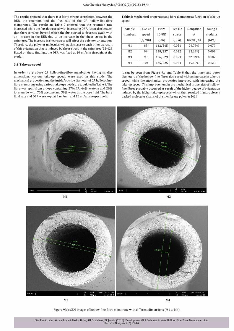
3.4 Take-up speed
In order to produce CA hollow-fine-fibre membranes having smaller dimensions, various take-up speeds were used in this study. The
mechanical properties and the inside/outside diameter of CA hollow-fine-fibre membrane using various take-up speeds are tabulated in Table 8. The
fibre was spun from a dope containing 27% CA, 44% acetone and 29%
formamide, with 70% acetone and 30% water as the bore fluid. The bore
fluid rate and DER were kept at 3 ml/min and 10 ml/min respectively.
Table 8: Mechanical properties and fibre diameters as function of take-up
speed
Sample
numbers
Take-up
speed
(r/min)
Fibre
ID/OD
(μm)
Tensile
stress
(GPa)
Elongation
at
break (%)
Young’s
modulus
(GPa)
M1 88 142/245 0.021 26.75% 0.077
M2 94 138/237 0.022 22.19% 0.099
M3 99 136/229 0.023 22. 19% 0.102
M4 104 135/225 0.024 19.10% 0.123
It can be seen from Figure 9.a and Table 8 that the inner and outer diameters of the hollow-fine fibres decreased with an increase in take-up
speed, while the mechanical properties improved with increasing the
take-up speed. This improvement in the mechanical properties of hollow-fine fibres probably occurred as result of the higher degree of orientation
induced by the higher take-up speeds which then resulted in more closely
packed molecular chains of the membrane polymer [43].
M1 M2
M3 M4
Figure 9(a): SEM images of hollow-fine-fibre membrane with different dimensions (M1 to M4).
Acta Chemica Malaysia (ACMY)2(2) (2018) 29-44
Cite The Article: Akram Tawari, Bashir Brika, SM Bradshaw, EP Jacobs (2018). Development Of A Cellulose Acetate Hollow-Fine-Fibre Membrane. Acta Checmica Malaysia, 2(2):29-44.
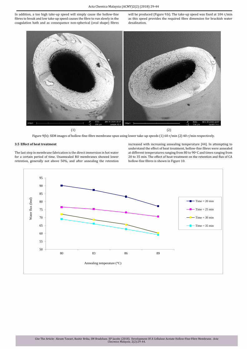
In addition, a too high take-up speed will simply cause the hollow-fine
fibres to break and low take-up speed causes the fibre to run slowly in the
coagulation bath and as consequence non-spherical (oval shape) fibres
will be produced (Figure 9.b). The take-up speed was fixed at 104 r/min
as this speed provides the required fibre dimension for brackish water desalination.
(1) (2)
Figure 9(b): SEM images of hollow-fine-fibre membrane spun using lower take-up speeds (1) 60 r/min (2) 40 r/min respectively.
3.5 Effect of heat treatment
The last step in membrane fabrication is the direct immersion in hot water for a certain period of time. Unannealed RO membranes showed lower retention, generally not above 50%, and after annealing the retention
increased with increasing annealing temperature [44]. In attempting to
understand the effect of heat treatment, hollow-fine fibres were annealed
at different temperatures ranging from 80 to 90o C and times ranging from
20 to 35 min. The effect of heat treatment on the retention and flux of CA
hollow-fine fibres is shown in Figure 10.
50
55
60
65
70
75
80
85
90
95
80 83 86 89
Wat
er f
lux (
lmd
)
Annealing temperature (°C)
Time = 20 min
Time = 25 min
Time = 30 min
Time = 35 min
Acta Chemica Malaysia (ACMY)2(2) (2018) 29-44
Cite The Article: Akram Tawari, Bashir Brika, SM Bradshaw, EP Jacobs (2018). Development Of A Cellulose Acetate Hollow -Fine-Fibre Membrane. Acta Checmica Malaysia, 2(2):29-44.
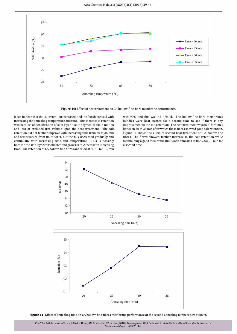
Figure 10: Effect of heat treatment on CA hollow-fine-fibre membrane performance.
It can be seen that the salt retention increased, and the flux decreased with
increasing the annealing temperature and time. This increase in retention
was because of densification of skin layer due to segmental chain motion
and loss of excluded free volume upon the heat treatment. The salt retention did not further improve with increasing time from 30 to 35 min
and temperature from 86 to 90 oC but the flux decreased gradually and
continually with increasing time and temperature. This is possibly
because the skin layer consolidates and grows in thickness with increasing
time. The retention of CA hollow-fine fibres annealed at 86 o C for 30, min
was 90% and flux was 65 L/m2.d. The hollow-fine-fibre membranes
bundles were heat treated for a second time to see if there is any
improvement in the salt retention. The heat treatment was 86o C for times between 20 to 35 min after which these fibres showed good salt retention. Figure 11 shows the effect of second heat treatment on CA hollow-fine
fibres. The fibres showed further increase in the salt retention while
maintaining a good membrane flux, when annealed at 86 o C for 30 min for a second time.
Figure 11: Effect of annealing time on CA hollow-fine-fibres membrane performance at the second annealing temperature at 86 o C.
70
75
80
85
90
95
80 83 86 89
Sal
t re
ten
tion
(%
)
Annealing temperature ( °C)
Time = 20 min
Time = 25 min
Time = 30 min
Time = 35 min
40
42
44
46
48
50
52
54
20 25 30 35
Flu
x (
lmd)
Annealing time (min)
91
92
93
94
95
20 25 30 35
Ret
net
ion
(%
)
Annealing time (min)

Acta Chemica Malaysia (ACMY)2(2) (2018) 29-44
Cite The Article: Akram Tawari, Bashir Brika, SM Bradshaw, EP Jacobs (2018). Development Of A Cellulose Acetate Hollow-Fine-Fibre Membrane. Acta Checmica Malaysia, 2(2):29-44.
The salt retention increased to about 94.5% and the flux decreased to 45
L/m2.d. Thus, the process of a second annealing time for the fibre bundle
yielded CA hollow-fine-fibre membranes with higher salt retention.
The first heating is carried out after relaxing the freshly spun fibre in fresh
water for a day which is mainly done to remove excess solvent. There are
two heat relaxation processes, firstly heat consolidation and densification
of the upper-most skin layer, i.e. removing pores are tiny flaws and are
undesirable, and secondly the tightening of the amorphous underlying
area which hinders the flux. This underlayer will continuously tighten
whether from temperature or time (as it is a viscoelastic phenomena).
Densifying the skin is problematic as plateaus occur after 30 min at 86 o C
(Figure 11) as the last pores do not close easily (retention still not at maximum). If the membrane is now left for a day to relax at room
temperature in water, then hard to explain but on reheating up to a
maximum heating time for 30 min at 86 o C, the consolidation of the skin
and underlayer (the latter with loss of flux) both occurs again as the first case and again the retention reaches a plateaus value. This has never been
reported before in literature. It was not thought necessary to do it a third
or fourth time as the amount of gain of retention still possible for CA is negligible and the flux will continue to drop.
One can surmise that in the skin layer, as the pores close, the OH groups, which are at a level of 2.45 degree of substitution, tend to hydrogen bond
leaving a stable pore or capillary and result in a plateau value for retention. During relaxation, rearrangement of CA molecules can occur to preferred
orientations and a partial loss of the less stable H-bonded enclosed pores. The second heating leads to further tightening and rearrangement easing
closing of the pores until only small fraction of OH groups persist to give
unclosed pores and another plateau value occurs. 100% retention is not possible with CA. One can carry on tightening the skin layer, but the flux
suffers too much because of this and the tightening of the porous.
4. CONCLUSIONS
The main objective of this research was the development of a CA hollow-fine-fibre membrane for brackish water desalination with good
performance from first principles. The influence of different variables pertaining to the fabrication process was studied and the overall conclusions of the research are as follows:
The spinning parameters such as solvent/nonsolvent ratio, bore fluid
ratio, dope extrusion rate, take-up speeds and heat treatment were
studied in terms of their effect on the fibre morphology. The elimination
of macrovoids from the morphology of hollow-fine-fibre membranes was achieved in two ways. Firstly, increasing the formamide ratio in the
polymer solution and secondly, decreasing the water activity in the bore
fluid by adding a solvent (acetone) to water.
The presence of solvent in the bore fluid decreased the water activity and
produced hollow-fine-fibre membranes with a sponge-like structure that improved the membrane flux and retention performance. SEM images showed that the fibres consist of a very thin dense surface layer, followed
by a fine porous sub-layer, with increasingly larger pore sizes as the
distance from the outer interface increases.
An increase of dope extrusion rate induces a high shear stress inside the
spinneret wall and subsequently increases the molecular orientation in
skin layer of asymmetric hollow-fine-fibre membranes. This effect improved the retention of the membranes while leading to a slight reduction in flux. Both the inner and outer diameter of the hollow fibre
decreased with increasing the take-up speeds resulting in a fibre
dimensions within the required region for brackish water operating
pressure. The mechanical strength of the fibres increased with increasing
take-up speeds. This could be attributed to the higher orientation caused
by higher temperature of 86 o C and annealing period of two subsequent times.
4.1 Recommendations for future work
1. Develop large working modules with thousands of hollow-fine-fibre
membranes.
2. Use the newest technology in ultrafiltration and use the
ultrafiltration water as feed for long term testing of these modules.
Wear, tear (breakage, collapse), performance (retention and flux) and fouling (pore and surface blocking) as a function of time.
3. Most important is the need to automate the membrane production
to make it repeatable in computer controllable.
4. Search for more friendly solvent systems e.g. alcohol instead of formamide in the preparation of CA hollow-fine-fibre membranes.
REFERENCES
[1] Baker, R.W. 2004. Membrane Technology and Applications, 2nd Ed, John Wiley & Sons, Chichester.
[2] Lonsdale, H.K. 1966. Desalination by Reverse Osmosis, Merten, U. (Ed.), MIT Press, Cambridge, MA.
[3] Dresner, L., Johonson, J.S. 1975. Principles of Desalination, Academic
Press, New York.
[4] Sourirajan, S. 1981. Reverse Osmosis: A new field of applied chemistry
and chemical engineering, American Chemical Society Symposium, 11.
[5] Lonsdale, H.K. 1966. Desalination by Reverse Osmosis, Merten, U. (Ed.), MIT Press, Cambridge, MA.
[6] Loeb, S., Sourirajan, S. 1960. New water desalting process developed
at University of California, University of California, Los Angeles, UCLA
Report, 60.
[7] Reid, C. E. and Breton, E. J., Water and ion flow across cellulosic
membranes, Journal of Applied Polymer Science, 1959, 1, 133.
[8] Riley, R.L., Merten, U., Gardner, J.O. 1966. Replication electron
microscopy of cellulose acetate osmotic membranes, Desalination, 1, 30.
[9] Petersen, R.J., Cadotte, J.E. 1990. Thin film composite reverse osmosis
membranes, Handbook of industrial membrane technology, Porter, M. C. (Ed.), Noyes Publications, Park Ridge.
[10] Riley, R.L. 1991. Membrane Separation Systems, Baker, R.W., Cussler, E.L., Eykamp, W., Koros, W.J., Riley, R.L., Strathmann, H. (Ed.), Noyes Data Corporation, New Jersey.
[11] Malm, C.J., Tanghe, L.J., Laird, B.C. 1946. Preparation of cellulose
acetate- Action of sulfuric acid, Industrial & Engineering Chemistry, 38, 77.
[12] Mulder, M. 1996. Basic Principles of Membrane Technology, Kluwer Academic Publishers, The Netherlands.
[13] Strathmann, H. 1985. Production of Microporous Media by Phase
Inversion Process, In: Material Science of Synthetic Membranes, LIoyd,
D.R. (Ed.), American Chemical Society, Washington D.C.
[14] Kesting, R.E. 1985. Phase Inversion Membranes, In: Synthetic
Polymeric Membranes, John Wiley & Sons, New York.
[15] Frommer, M.A., Lancet, D. 1972. Reverse osmosis membrane
research, Lonsdale, H., Podall, H.E. (Ed.), Plenum Press, 85.
[16] Smolders, C.A., Reuvers, A.J., Boom, R.M., Wienk, I.M. 1992. Microstructures in phase-inversion membranes. Part 1. Formation of macrovoids, Journal of Membrane Science, 73, 259.
[17] Frommer, M.A., Messalem, R.M. 1973. Mechanism of membrane
formation. VI. Convective flows and large void formation during
membrane precipitation, Industrial and Engineering Chemistry Product research and development, 12, 328.
[18] Idris, A., Ismail, A.F., Noordin, M.Y., Shilton, J.S. 2002. Optimization
of cellulose acetate hollow fibre reverse osmosis membrane production
using Taguchi method, Journal of Membrane Science, 223.
[19] Pesek, S.C., Koros, W.J. 1994. Aqueous quenched asymmetric polysulfone hollow fibres prepared by dry/wet phase separation, Journal
of Membrane Science, 88, 1.

Acta Chemica Malaysia (ACMY)2(2) (2018) 29-44
Cite The Article: Akram Tawari, Bashir Brika, SM Bradshaw, EP Jacobs (2018). Development Of A Cellulose Acetate Hollow -Fine-Fibre Membrane. Acta Checmica Malaysia, 2(2):29-44.
[20] Ismail, A.F., Dunkin, I.R., Gallivan, S.L., Shilton, S.J. 1999. Production
of super selective polysulfone hollow fibre membranes for gas separation, Polymer, 40, 6499.
[21] Wang, D., Li, K., Teo, W.K. 2000. Highly permeable polyethersulfone
hollow fibre gas separation membranes prepared using water as non-solvent additive, Journal of Membrane Science, 176, 147.
[22] Idris, A., Ismail, A.F., Gordeyev, S.A., Shilton, S.J. 2003. Rheology
assessment of cellulose acetate spinning solution and its influence on
reverse osmosis hollow fibre membrane performance, Polymer Testing,
22, 319.
[23] So, M.T., Eirich, F.R., Strathmann, H., Baker, R.W. 1973. Preparation
of asymmetric Loeb-Sourirajan membranes, Jouranl of Polymer Science, Part C: Polymer Letters, 11, 201.
[24] So, M.T., Eirich, F.R., Strathmann, H., Baker, R.W. 1973. Preparation
of anisotropic Loeb-Sourirajan Membranes, Polymer letters, 201.
[25] Kesting, R.E. 1985. Synthetic Polymeric Membranes: A Structural Perspective, Wiley-Interscience, New York.
[26] Pinnau, I., Wind, J., Peineman, K.V. 1990. Ultrathin multicomponent poly (ether sulfone) membrane for gas separation made by dry/wet phase
inversion, Industrial and Engineering Chemistry Research, 29, 2028.
[27] Manjikian, S. 1967. Desalination membranes from organic casting
solutions, Industrial and Engineering Chemistry Product Research and
Development, 6, 23.
[28] Jacobs, E.P. 1988. Statistical and numerical techniques in the
optimization of membrane fabrication variables, PhD Thesis, University of Stellenbosch, South Africa.
[29] Qin, J.J., Wang, R., Chung, T.S. 2000. Investigation of shear stress effect within a spinneret on flux, separation and thermomechanical
properties of hollow fibre ultrafiltration membranes, Journal of Membrane
Science, 175, 197.
[30] Shieh, J.J., Chung, T.S. 1998. Effect of liquid-liquid demixing on the
membrane morphology, gas permeation, thermal and mechanical
properties of cellulose acetate hollow fibres, Journal of Membrane Science, 140, 67. [31] Qin, J.J., Li, Y., Lee, L.S., Lee, H. 2003. Cellulose acetate hollow fibre
ultrafiltration membranes made from CA/PVP 360 K/NMP/water, Journal
of Membrane Science, 218, 173.
[32] Pinnau, I., Koros, W.J. 1990. Defect free ultra-high flux asymmetric
membranes, U.S. patent 4,902,422.
[33] Pesek, S.C., Koros, W.J. 1993. Aqueous quenched asymmetric polysulphone membranes prepared by dry/wet phase separation, Journal
of Membrane Science, 81, 71.
[34] Pinnau, I., Wind, J., Pieneman, K.V. 1990. Ultrathin multicomponent polyethersulphone membranes for gas separation made by dry/wet phase
inversion, Industrial and Engineering Chemistry Research, 29, 2028.
[35] Chung, T.S., Xu, Z.L. 1997. Effect of air-gap distance on the
morphology and thermal properties of polyethersulfone hollow fibres, Journal of Applied Polymer Science, 66, 1067.
[36] Aptel, P., Abidine, N., Ivaldi, F., Lafaille, J.P. 1985. Polysulphone
hollow fibres-effect of spinning conditions on ultrafiltration properties, Journal of Membrane Science, 22, 199.
[37] Liu, T., Zhang, D., Xu, S., Sourirajan, S. 1992. Solution-spin hollow
fibre polysulfone and polyethersulfone ultrafiltration membranes, Separation Science and Technology, 27, 161.
[38] Wang, D., Li, K., Teo, W.K. 1998. Preparation and characterization of polyetherimide asymmetric hollow fibre membranes for gas separation, Journal of Membrane Science, 1998, 138, 193.
[39] Chung, T.S., Xu, Z.L., Lin, W.H. 1999. Fundamental understanding of the effect of air-gap distance on the fabrication of hollow fibre membranes, Separation and Purification Technology, 72(3), 379
[40] Chau, J.L., Wang, S.S., Guo, C.L. 1995. Pilot production of pulysulfone
hollow fibre for ultra-filtration using orthogonal array experimentation, Industrial and Engineering Chemistry Research, 34, 803
[41] Ismail, A.F., Mustaffar, M.I., Illias, R.M., Abdullah, M.S. 2006. Effect of dope extrusion rate on morphology and performance of hollow fibres membrane for ultrafiltration, Separation and Purification Technology, 49, 10.
[42] Idris, A., Noordin, M.Y., Ismail, A.F., Shilton, S.J. 2002. Study of shear rate influence on the performance of cellulose acetate reverse osmosis
hollow fibre membranes, Journal of Membrane Science, 202, 205.
[43] Chou, W.L., Yang, M.C. 2005. Effect of take-up speed on physical properties and permeation performance of cellulose acetate hollow fibres, Journal of Membrane Science, 250, 259.
[44] Gittens, G.J., Hitchcock, P.A., Sammon, D.C., Wakley, G.E. 1970. The
structure of cellulose acetate membranes for reverse osmosis. Part I. Membranes prepared from a dioxane based dope, Desalination, 8, 369.
![Ferguson, John. Bibliotheca chemica [Document … · Title: Ferguson, John. Bibliotheca chemica [Document électronique] : a catalogue of the alchemical, chemical and pharmaceutical](https://img.pdfslide.us/doc/110x75/5b8952767f8b9aa81a8c36be/ferguson-john-bibliotheca-chemica-document-title-ferguson-john-bibliotheca.jpg)