Embed Size (px)
Citation preview

Development of a Biofidelic Artificial Arm for a Martial Arts
Dummy
David Shapiro
A thesissubmitted in partial fulfillment ofthe requirements for the degree of
Master of Science in Mechanical Engineering
University of Washington
2011
Randal P. Ching, ChairBrian C. FabienMichael E. Hahn
Program Authorized to Offer Degree:Mechanical Engineering


University of Washington
Abstract
Development of a Biofidelic Artificial Arm for a Martial Arts Dummy
David Shapiro
Chair of the Supervisory Committee:Research Associate Professor Randal P. Ching
Mechanical Engineering
There are currently no martial art dummies or training devices that offer biofidelic
recreation of human joints and resistance. Having access to this type of training tool
could greatly improve a martial artist’s skill in the area of joint manipulations. To fill
this gap in the marketplace, one subsystem of such a device, the arm, was modeled
in SolidWorks and then built for testing. Design focused on the shoulder; the rest of
the arm was built primarily to test the shoulder joint. The final design was made to
match 50th percentile male specifications and mimic moderate muscular resistance.
The resulting prototype was shown to work well for joint locks that only involve the
arm (i.e. no bending at the waist or knees). Such a device represents a first in this
area.

TABLE OF CONTENTS
Page
List of Figures . . . . . . . . . . . . . . . . . . . . . . . . . . . . . . . . . . . iv
List of Tables . . . . . . . . . . . . . . . . . . . . . . . . . . . . . . . . . . . . vii
Chapter 1: Introduction . . . . . . . . . . . . . . . . . . . . . . . . . . . . 1
1.1 Market Background . . . . . . . . . . . . . . . . . . . . . . . . . . . . 1
1.2 Objective . . . . . . . . . . . . . . . . . . . . . . . . . . . . . . . . . 4
1.3 Project Overview . . . . . . . . . . . . . . . . . . . . . . . . . . . . . 6
1.4 Project Deliverables . . . . . . . . . . . . . . . . . . . . . . . . . . . . 6
1.5 The Human Shoulder . . . . . . . . . . . . . . . . . . . . . . . . . . . 6
1.6 Previous Work and Similar Designs . . . . . . . . . . . . . . . . . . . 8
1.7 Summary . . . . . . . . . . . . . . . . . . . . . . . . . . . . . . . . . 12
Chapter 2: Design . . . . . . . . . . . . . . . . . . . . . . . . . . . . . . . . 13
2.1 Selected Design Requirements . . . . . . . . . . . . . . . . . . . . . . 13
2.2 Designs Considered . . . . . . . . . . . . . . . . . . . . . . . . . . . . 14
2.3 Design Selected . . . . . . . . . . . . . . . . . . . . . . . . . . . . . . 16
2.4 Design Details . . . . . . . . . . . . . . . . . . . . . . . . . . . . . . . 17
2.4.1 The Mount Assembly . . . . . . . . . . . . . . . . . . . . . . . 17
2.4.2 The Shoulder Assembly . . . . . . . . . . . . . . . . . . . . . 18
2.4.3 The Upper Arm Assembly . . . . . . . . . . . . . . . . . . . . 19
2.4.4 The Elbow Assembly . . . . . . . . . . . . . . . . . . . . . . . 19
2.4.5 The Forearm Assembly . . . . . . . . . . . . . . . . . . . . . . 20
2.4.6 The Final Arm Assembly . . . . . . . . . . . . . . . . . . . . . 21
2.5 Design Considerations . . . . . . . . . . . . . . . . . . . . . . . . . . 22
2.5.1 Simplicity . . . . . . . . . . . . . . . . . . . . . . . . . . . . . 22
2.5.2 Weight . . . . . . . . . . . . . . . . . . . . . . . . . . . . . . . 23
i

2.5.3 Resistance . . . . . . . . . . . . . . . . . . . . . . . . . . . . . 23
2.5.4 Range of Motion . . . . . . . . . . . . . . . . . . . . . . . . . 27
2.6 Summary . . . . . . . . . . . . . . . . . . . . . . . . . . . . . . . . . 28
Chapter 3: The Prototype . . . . . . . . . . . . . . . . . . . . . . . . . . . 29
3.1 Manufacturing . . . . . . . . . . . . . . . . . . . . . . . . . . . . . . . 29
3.1.1 The Mount Assembly . . . . . . . . . . . . . . . . . . . . . . . 29
3.1.2 The Shoulder Assembly . . . . . . . . . . . . . . . . . . . . . 30
3.1.3 The Upper Arm Assembly . . . . . . . . . . . . . . . . . . . . 33
3.1.4 The Forearm Assembly . . . . . . . . . . . . . . . . . . . . . . 37
3.2 Cabling . . . . . . . . . . . . . . . . . . . . . . . . . . . . . . . . . . 44
3.3 Final Assembly . . . . . . . . . . . . . . . . . . . . . . . . . . . . . . 45
3.4 Final Evaluation . . . . . . . . . . . . . . . . . . . . . . . . . . . . . 46
3.4.1 Resistance . . . . . . . . . . . . . . . . . . . . . . . . . . . . . 46
3.4.2 Range of Motion . . . . . . . . . . . . . . . . . . . . . . . . . 47
3.4.3 Poseability . . . . . . . . . . . . . . . . . . . . . . . . . . . . . 49
3.5 Summary . . . . . . . . . . . . . . . . . . . . . . . . . . . . . . . . . 50
Chapter 4: Conclusions . . . . . . . . . . . . . . . . . . . . . . . . . . . . . 51
4.1 Future Design Improvements . . . . . . . . . . . . . . . . . . . . . . . 51
4.1.1 Fasteners and Modularity . . . . . . . . . . . . . . . . . . . . 51
4.1.2 The Mount Assembly . . . . . . . . . . . . . . . . . . . . . . . 51
4.1.3 The Shoulder Assembly . . . . . . . . . . . . . . . . . . . . . 52
4.1.4 The Upper Arm Assembly . . . . . . . . . . . . . . . . . . . . 53
4.1.5 The Elbow Assembly . . . . . . . . . . . . . . . . . . . . . . . 53
4.1.6 The Forearm Assembly . . . . . . . . . . . . . . . . . . . . . . 54
4.1.7 Resistance and Range of Motion . . . . . . . . . . . . . . . . . 54
4.2 Future Work . . . . . . . . . . . . . . . . . . . . . . . . . . . . . . . . 55
4.2.1 Structural Analysis . . . . . . . . . . . . . . . . . . . . . . . . 55
4.2.2 Instrumentation . . . . . . . . . . . . . . . . . . . . . . . . . . 56
4.2.3 Actuation . . . . . . . . . . . . . . . . . . . . . . . . . . . . . 57
4.2.4 Outer Covering . . . . . . . . . . . . . . . . . . . . . . . . . . 57
4.2.5 Completing the Dummy . . . . . . . . . . . . . . . . . . . . . 58
ii

4.3 Other Applications . . . . . . . . . . . . . . . . . . . . . . . . . . . . 58
4.4 Summary . . . . . . . . . . . . . . . . . . . . . . . . . . . . . . . . . 58
4.5 Conclusion . . . . . . . . . . . . . . . . . . . . . . . . . . . . . . . . . 59
Appendix A: Drawings . . . . . . . . . . . . . . . . . . . . . . . . . . . . . . 62
A.1 The Mount Assembly . . . . . . . . . . . . . . . . . . . . . . . . . . . 62
A.2 The Shoulder Assembly . . . . . . . . . . . . . . . . . . . . . . . . . . 65
A.3 The Upper Arm Assembly . . . . . . . . . . . . . . . . . . . . . . . . 71
A.4 The Elbow Assembly . . . . . . . . . . . . . . . . . . . . . . . . . . . 77
A.5 The Forearm Assembly . . . . . . . . . . . . . . . . . . . . . . . . . . 80
Appendix B: Calculations . . . . . . . . . . . . . . . . . . . . . . . . . . . . . 86
B.1 Upper Arm Spring Calculation . . . . . . . . . . . . . . . . . . . . . . 86
B.2 Shoulder Flexion and Extension Weight Calculation . . . . . . . . . . 87
B.3 Shoulder Flexion and Extension Force Calculation . . . . . . . . . . . 89
Appendix C: Design Requirements . . . . . . . . . . . . . . . . . . . . . . . . 92
iii

LIST OF FIGURES
Figure Number Page
1.1 Striking dummmies . . . . . . . . . . . . . . . . . . . . . . . . . . . . 2
1.2 Grappling dummmies . . . . . . . . . . . . . . . . . . . . . . . . . . . 3
1.3 The 50th percentile male . . . . . . . . . . . . . . . . . . . . . . . . . 4
1.4 The human shoulder . . . . . . . . . . . . . . . . . . . . . . . . . . . 7
1.5 Humanoid shoulder-elbow complex . . . . . . . . . . . . . . . . . . . 9
1.6 9-DOF arm . . . . . . . . . . . . . . . . . . . . . . . . . . . . . . . . 9
1.7 Hybrid III crash test dummy . . . . . . . . . . . . . . . . . . . . . . . 10
1.8 THOR shoulder assembly . . . . . . . . . . . . . . . . . . . . . . . . 11
2.1 Designs considered for the shoulder . . . . . . . . . . . . . . . . . . . 15
2.2 Rendering of final design in SolidWorks . . . . . . . . . . . . . . . . . 17
2.3 The mount assembly . . . . . . . . . . . . . . . . . . . . . . . . . . . 18
2.4 The shoulder assembly . . . . . . . . . . . . . . . . . . . . . . . . . . 19
2.5 The upper arm assembly . . . . . . . . . . . . . . . . . . . . . . . . . 20
2.6 The forearm assembly . . . . . . . . . . . . . . . . . . . . . . . . . . 21
2.7 The fully assembled arm . . . . . . . . . . . . . . . . . . . . . . . . . 22
2.8 Simplified free-body diagram for upper arm . . . . . . . . . . . . . . 24
2.9 Simplified free-body diagram for horizontal arm position . . . . . . . 27
3.1 Prototype mount assembly . . . . . . . . . . . . . . . . . . . . . . . . 30
3.2 Assembling the mount . . . . . . . . . . . . . . . . . . . . . . . . . . 31
3.3 Prototype flexion/extension lock . . . . . . . . . . . . . . . . . . . . . 32
3.4 Prototype shoulder axle . . . . . . . . . . . . . . . . . . . . . . . . . 32
3.5 Assembling the shoulder . . . . . . . . . . . . . . . . . . . . . . . . . 34
3.6 Prototype bearing lock . . . . . . . . . . . . . . . . . . . . . . . . . . 35
3.7 Prototype torsion spring lock . . . . . . . . . . . . . . . . . . . . . . 35
3.8 Prototype upper arm bone . . . . . . . . . . . . . . . . . . . . . . . . 36
3.9 Prototype upper arm tube . . . . . . . . . . . . . . . . . . . . . . . . 37
iv
3.10 Assembling the upper arm . . . . . . . . . . . . . . . . . . . . . . . . 38
3.11 Prototype clevis connector . . . . . . . . . . . . . . . . . . . . . . . . 39
3.12 Prototype forearm tube . . . . . . . . . . . . . . . . . . . . . . . . . . 40
3.13 Prototype forearm bone . . . . . . . . . . . . . . . . . . . . . . . . . 40
3.14 Prototype hand . . . . . . . . . . . . . . . . . . . . . . . . . . . . . . 41
3.15 Assembling the forearm . . . . . . . . . . . . . . . . . . . . . . . . . . 42
3.16 Cable attachments . . . . . . . . . . . . . . . . . . . . . . . . . . . . 44
3.17 Assembling the arm . . . . . . . . . . . . . . . . . . . . . . . . . . . . 46
3.18 Shoulder range of motion . . . . . . . . . . . . . . . . . . . . . . . . . 48
3.19 Poseable arm positions . . . . . . . . . . . . . . . . . . . . . . . . . . 49
A.1 Exploded view of mount assembly . . . . . . . . . . . . . . . . . . . . 63
A.2 Part drawing of mounting plate . . . . . . . . . . . . . . . . . . . . . 64
A.3 Exploded view of shoulder assembly . . . . . . . . . . . . . . . . . . . 66
A.4 Part drawing of flexion/extension lock rod . . . . . . . . . . . . . . . 67
A.5 Part drawing of shoulder axle . . . . . . . . . . . . . . . . . . . . . . 68
A.6 Part drawing of shoulder tube . . . . . . . . . . . . . . . . . . . . . . 69
A.7 Part drawing of flexion/extension lock tube . . . . . . . . . . . . . . . 70
A.8 Exploded view of upper arm assembly . . . . . . . . . . . . . . . . . 72
A.9 Part drawing of bearing lock . . . . . . . . . . . . . . . . . . . . . . . 73
A.10 Part drawing of torsion spring lock . . . . . . . . . . . . . . . . . . . 74
A.11 Part drawing of upper arm bone . . . . . . . . . . . . . . . . . . . . . 75
A.12 Part drawing of upper arm tube . . . . . . . . . . . . . . . . . . . . . 76
A.13 Elbow assembly . . . . . . . . . . . . . . . . . . . . . . . . . . . . . . 78
A.14 Part drawing of elbow linkage . . . . . . . . . . . . . . . . . . . . . . 79
A.15 Exploded view of forearm assembly . . . . . . . . . . . . . . . . . . . 81
A.16 Part drawing of clevis connector . . . . . . . . . . . . . . . . . . . . . 82
A.17 Part drawing of forearm tube . . . . . . . . . . . . . . . . . . . . . . 83
A.18 Part drawing of forearm bone . . . . . . . . . . . . . . . . . . . . . . 84
A.19 Part drawing of hand . . . . . . . . . . . . . . . . . . . . . . . . . . . 85
B.1 Simplified free-body diagram for upper arm . . . . . . . . . . . . . . 86
B.2 Simplified free-body diagram of arm . . . . . . . . . . . . . . . . . . . 88
B.3 Simplified free-body diagram of arm in 45 degree position . . . . . . . 89
v

C.1 The 50th percentile male . . . . . . . . . . . . . . . . . . . . . . . . . 93
vi

LIST OF TABLES
Table Number Page
1.1 Comparison of dummy attributes . . . . . . . . . . . . . . . . . . . . 5
2.1 Arm Strength in Pounds [NASA, 1995] . . . . . . . . . . . . . . . . . 25
2.2 Maximum Arm Torque Strengths [NASA, 1995] . . . . . . . . . . . . 26
2.3 Design goals met . . . . . . . . . . . . . . . . . . . . . . . . . . . . . 28
3.1 BOM for prototype . . . . . . . . . . . . . . . . . . . . . . . . . . . . 43
A.1 BOM for mount assembly . . . . . . . . . . . . . . . . . . . . . . . . 62
A.2 BOM for shoulder assembly . . . . . . . . . . . . . . . . . . . . . . . 65
A.3 BOM for upper arm assembly . . . . . . . . . . . . . . . . . . . . . . 71
A.4 BOM for elbow assembly . . . . . . . . . . . . . . . . . . . . . . . . . 77
A.5 BOM for forearm assembly . . . . . . . . . . . . . . . . . . . . . . . . 80
vii

ACKNOWLEDGMENTS
The author would like to thank his sponsor, Dave Grout; committee members,
Randal Ching, Brian Fabien, and Michael Hahn; and his wonderful family and friends
for all their support.
viii

DEDICATION
To my many Sensei.
ix


1
Chapter 1
INTRODUCTION
Within the martial arts world, there are two ways to practice: alone or with a
partner. While solo training has many benefits, most martial artists will agree that
training with a partner is far more beneficial. However, fellow martial artists are often
unavailable.
The underlying purpose of this project is to provide a useful surrogate for a human
training partner; that is, a dummy that will mimic the human body’s size, strength,
weight, and resistance. This dummy will allow a martial artist to practice various
techniques (e.g. joint locks and strikes) on something that behaves more realistically
than a heavy bag or empty air.
1.1 Market Background
Currently, there are several commercial products available with similar goals, but
none provide accurate biofidelic response.
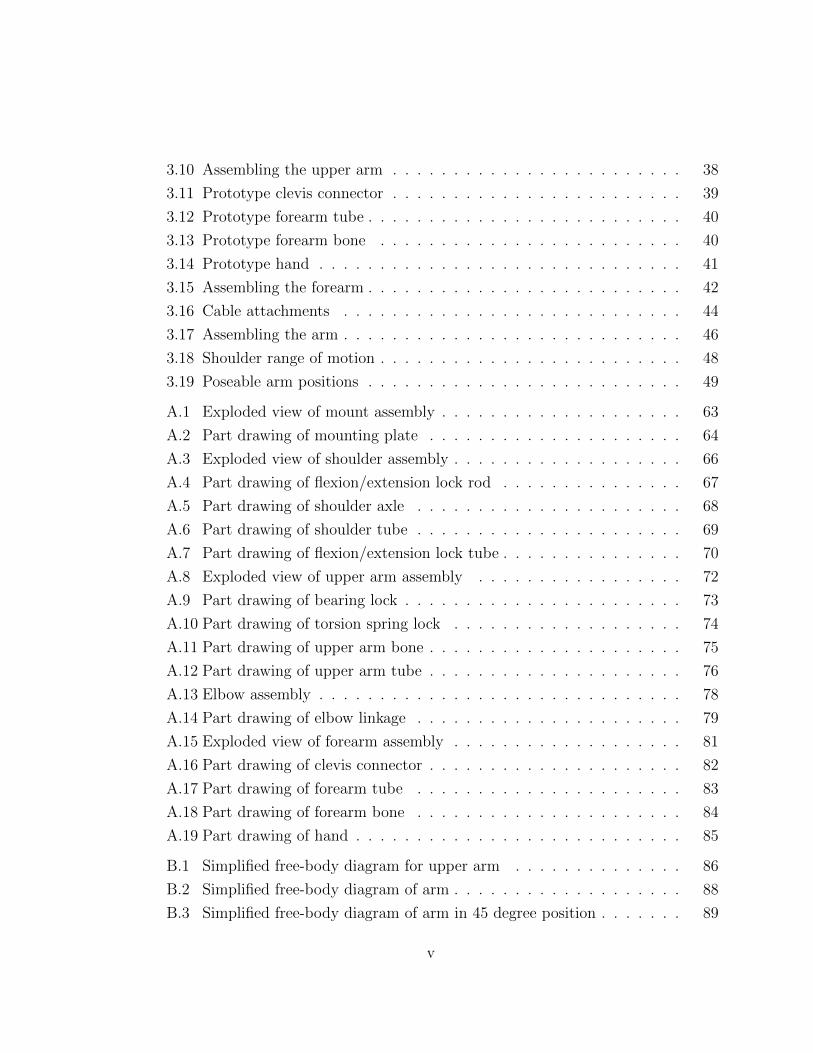
The first example of a training dummy is the classic Wing Chun Kung Fu wooden
dummy (Figure 1.1a1, Page 2). The horizontal pegs represent an opponent’s arms
and are generally struck with different parts of the body (fists, palms, arms, etc.) in
order to practice strikes and toughen striking surfaces. While very traditional, this
fails to provide much in the way of feedback or realism.
A more modern example, the amusingly named “Martial Arm” (Figure 1.1b2,
Page 2), offers some improvement over the Wing Chun dummy. This model provides
1Image source: http://www.wcarchive.com/wcasites/buickyipwingchun/wingchundummy.htm
2Image source: http://www.jumpusa.com/martial arm.html
2
(a) Wing Chun dummy (b) The Martial Arm
Figure 1.1: Striking dummmies
resistance to techniques performed on it; however, the strength of the springs inside
is excessive. Performing joint locks on the Martial Arm would require far more force
than would be necessary against a human being.
The previous two examples represent dummies designed primarily for striking
martial arts (boxing, karate, kung fu, etc.). They are built to withstand repeated
impacts but they are only useful for punches, kicks, and other striking techniques.
In contrast, the following examples are targeted more towards grappling arts (judo,
ju-jutsu, wrestling, etc.).
Pro Force’s 30 lb. “Grappling Man Dummy” (Figure 1.2a3, Page 3) finally looks
something like a human being. Unfortunately, it has no articulated joints. It is
effectively a sand bag with arms and legs. While somewhat suitable for grappling on
the ground, it would be useless for someone wishing to practice standing techniques.
The next option, Dummies Unlimited’s “Grapple Man” (Figure 1.2b4, Page 3),
3Image source: http://www.amazon.com/Pro-Force-Grappling-Man-Dummy/dp/B0034PSK7S
4Image source: http://www.dummiesunlimited.com/grappleman.htm

3
(a) Grappling Man dummy (b) Grapple
Man dummy
(c) Big Bubba dummy
Figure 1.2: Grappling dummmies
responds more like a rag doll. With no built-in resistance of any kind, it would
be like wrestling with someone who is already unconscious. Looking mostly like a
lighter, repurposed crash test dummy, this model fails to impress. While extremely
human in appearance and articulation, it lacks realism in all other areas. It would be
appropriately compared to a giant action figure: fun to play with but not particularly
useful.
Finally, there is I & I Sports’ “BIG Bubba II” (Figure 1.2c5, Page 3) which claims
to have “realistic, flexible joints”. This time, though the limbs seem to behave some-
what more realistically, the dummy is lacking in mass and size.
In general, manufacturers of grappling dummies tend to claim that they achieve
human mimicry with joints and resistance. Unfortunately for them, simply watching
demonstration videos shows arms that do not behave in a realistic manner. The
proposed design would fill a gap that currently exists in the market by providing a
5Image source: http://www.bubbadummy.com/

4
more realistic simulation of human appendages.
Conveniently, the end goal of this project is to produce a design that bridges the
gap between the two dummy genres. While primarily focused on standing techniques,
it will allow a martial artist to integrate joint locks and strikes without fear of injuring
a training partner. As such a device does not currently exist, this product will fill a
niche that is as yet unoccupied.
1.2 Objective
The specific goal of this project was to design an artificial arm for use in a human
simulacrum for martial arts training. The main focus of the project was the shoulder,
the most complex joint needed for accurate simulation of human arm motion. The rest
of the arm was built as well (though the elbow, hand, and wrist are only placeholders
for more complex subsystems). This allowed testing of the shoulder under appropriate
usage conditions.
This dummy is to be used for the training of joint locks and restraint techniques.
Figure 1.3: The 50th percentile male, see Appendix C for greater detail
5
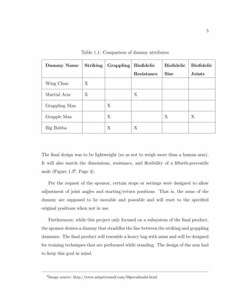
Table 1.1: Comparison of dummy attributes
Dummy Name Striking Grappling Biofidelic
Resistance
Biofidelic
Size
Biofidelic
Joints
Wing Chun X
Martial Arm X X
Grappling Man X
Grapple Man X X X
Big Bubba X X
The final design was to be lightweight (so as not to weigh more than a human arm).
It will also match the dimensions, resistance, and flexibility of a fiftieth-percentile
male (Figure 1.36, Page 4).
Per the request of the sponsor, certain stops or settings were designed to allow
adjustment of joint angles and starting/return positions. That is, the arms of the
dummy are supposed to be movable and poseable and will reset to the specified
original positions when not in use.
Furthermore, while this project only focused on a subsystem of the final product,
the sponsor desires a dummy that straddles the line between the striking and grappling
dummies. The final product will resemble a heavy bag with arms and will be designed
for training techniques that are performed while standing. The design of the arm had
to keep this goal in mind.
6Image source: http://www.adaptivemall.com/50peradmalsi.html
6
1.3 Project Overview
The project focused on the design of an artificial shoulder joint and culminated with
production of a prototype. After completion of a thorough review of the literature on
artificial shoulders and arms, a preliminary set of functional design requirements and
specifications was developed. The sponsor was then consulted to review and approve
the final design specifications.
Next, several different conceptual designs were developed, analyzed, and modeled.
The results of the analysis served as the basis for evaluation of the conceptual designs
and a final design that most closely matches the functional requirements and sponsor
specifications was recommended.
The final design was modeled and tested in SolidWorks, a combined computer-
aided design (CAD) and software modeling program. Biometric length, strength, and
flexibility data were be obtained from literature. This allowed creation of 3D CAD
drawings of the shoulder joint as well as 3D simulations of its motion.
A working prototype was then constructed. Necessary parts and raw materials
were ordered, or fabricated in preparation for assembly. For the sake of cost and sim-
plicity, attempts were made to use existing parts and inexpensive materials wherever
possible.
1.4 Project Deliverables
A copy of the Master’s thesis will serve as the final report to the sponsor. In addition,
a full set of CAD (SolidWorks) drawings of the final design will be provided on a CD-
ROM, and the final design prototype will be delivered to the sponsor.
1.5 The Human Shoulder
The human shoulder is a very complex joint. Before reviewing other attempts to
model the human shoulder, here is an overview of the shoulder and the terminology
7
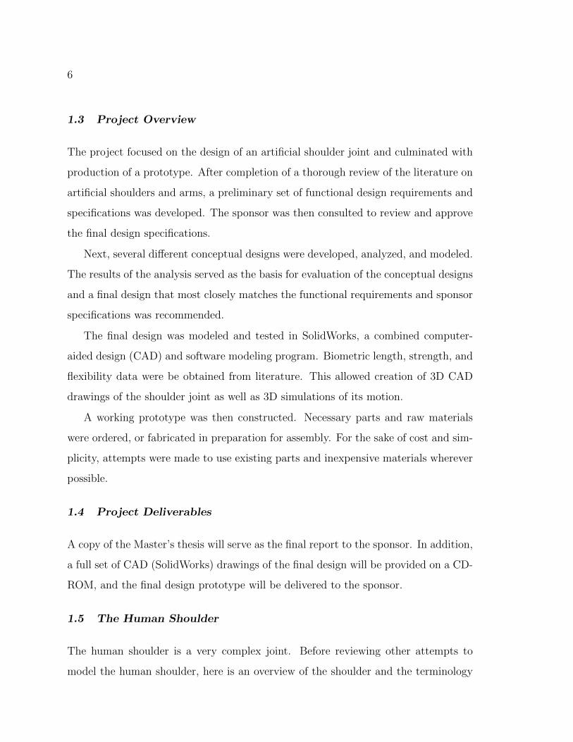
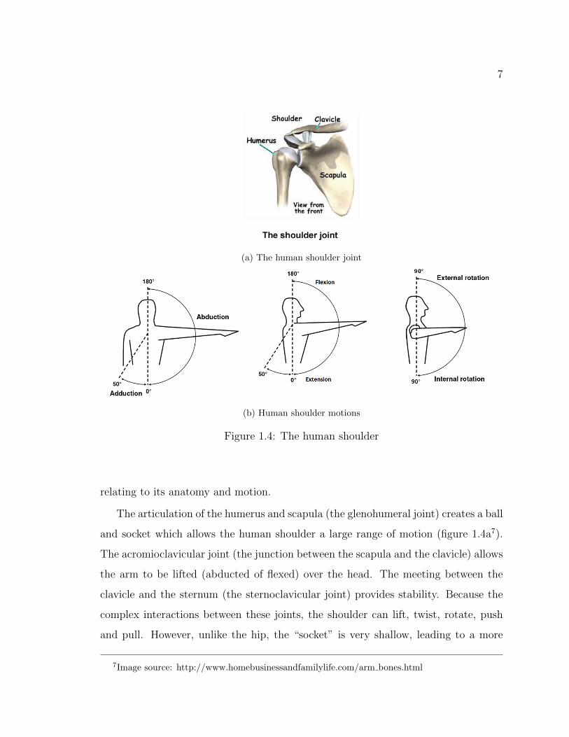
(a) The human shoulder joint
(b) Human shoulder motions
Figure 1.4: The human shoulder
relating to its anatomy and motion.
The articulation of the humerus and scapula (the glenohumeral joint) creates a ball
and socket which allows the human shoulder a large range of motion (figure 1.4a7).
The acromioclavicular joint (the junction between the scapula and the clavicle) allows
the arm to be lifted (abducted of flexed) over the head. The meeting between the
clavicle and the sternum (the sternoclavicular joint) provides stability. Because the
complex interactions between these joints, the shoulder can lift, twist, rotate, push
and pull. However, unlike the hip, the “socket” is very shallow, leading to a more
7Image source: http://www.homebusinessandfamilylife.com/arm bones.html
8
flexible but less stable joint.
The anatomical directions in which the shoulder joint can move, along with are
defined in figure 1.4b8. This yields a simple way of discussing the movement of the
shoulder in technical terms. For example, the act of bending over to touch one’s toes
means the shoulders flex (to approximately 90 degrees), rubbing one’s tummy means
the shoulder is rotated internally (approximately 90 degrees), and during jumping
jacks the shoulders abduct (approximately 180 degrees) and then adduct (0 degrees).
The angle definitions in figure 1.4b will be referenced throughout this document.
Note also that adduction and abduction can be separated into two movements: true
ad/abduction and up/downward rotation of the scapula. For simplicity’s sake how-
ever, scapular motion was largely ignored during this project.
Knowledge of how the shoulder’s anatomy informs attempts to replicate it me-
chanically. The shoulder’s complex joint configuration dictates that the final design
must have similar specifications (i.e. free rotation and movement over a large range
of motion).
1.6 Previous Work and Similar Designs
Most previous designs represent devices that are meant either for robots or are human
joint replacements. Of the two categories, the former is the more helpful. Most joint
replacements presuppose the existence of muscle, bone, and connective tissue which
limits their usefulness as inspiration (see Macgovern and Marra [2006] as an example
of the general uses of joint replacements). In the same vein, most humanoid robotic
arms are not biofidelic. They approximate the human arm and its range of motion,
but rarely do so in ways that exactly match human joints. That is, robotic arms can
reach all the same positions a human arm can, but they may have to travel there by
different paths. The following are several examples of interesting or relevant designs.
8Image source: http://www.ajronline.org/content/189/3/W128/F3.expansion.html

9
Figure 1.5: Humanoid shoulder-elbow complex from Goehler [2007], Agrawal andDubey [2009]
Figure 1.6: 9-DOF arm from Miwa et al. [2004]
Goehler [2007], Klopcar and Lenarcic [2001] propose a design that does an excel-
lent job of mimicking the human shoulder’s complexity (Figure 1.5, Page 9). Unfor-
tunately, this device is designed to be motor-actuated and move under its own power.
However interesting and useful it may be in the robotics community, it supplied little
helpful information for this project.
10
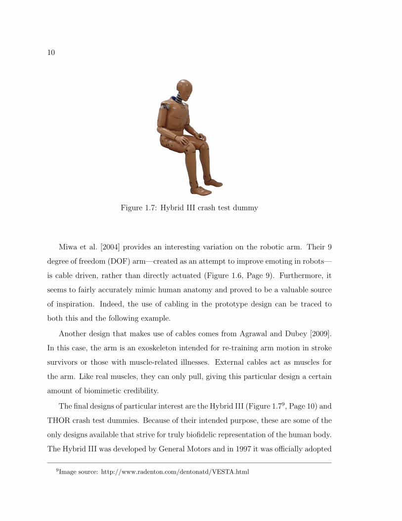
Figure 1.7: Hybrid III crash test dummy
Miwa et al. [2004] provides an interesting variation on the robotic arm. Their 9
degree of freedom (DOF) arm—created as an attempt to improve emoting in robots—
is cable driven, rather than directly actuated (Figure 1.6, Page 9). Furthermore, it
seems to fairly accurately mimic human anatomy and proved to be a valuable source
of inspiration. Indeed, the use of cabling in the prototype design can be traced to
both this and the following example.
Another design that makes use of cables comes from Agrawal and Dubey [2009].
In this case, the arm is an exoskeleton intended for re-training arm motion in stroke
survivors or those with muscle-related illnesses. External cables act as muscles for
the arm. Like real muscles, they can only pull, giving this particular design a certain
amount of biomimetic credibility.
The final designs of particular interest are the Hybrid III (Figure 1.79, Page 10) and
THOR crash test dummies. Because of their intended purpose, these are some of the
only designs available that strive for truly biofidelic representation of the human body.
The Hybrid III was developed by General Motors and in 1997 it was officially adopted
9Image source: http://www.radenton.com/dentonatd/VESTA.html
11
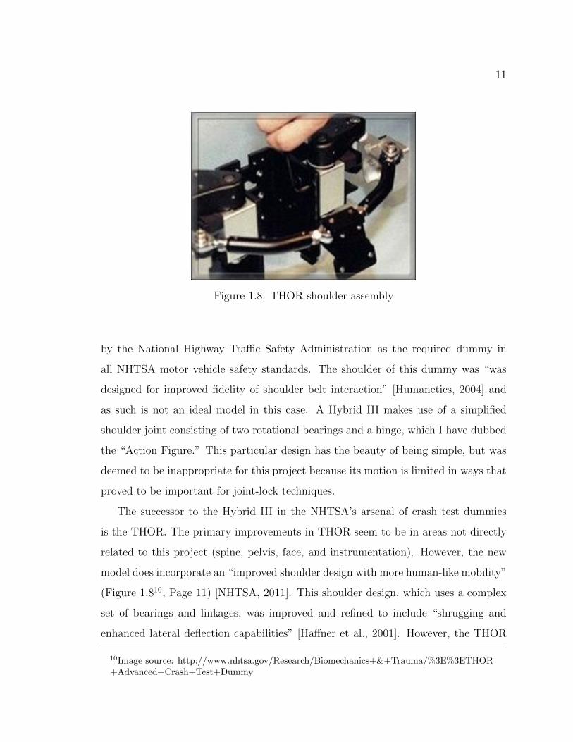
Figure 1.8: THOR shoulder assembly
by the National Highway Traffic Safety Administration as the required dummy in
all NHTSA motor vehicle safety standards. The shoulder of this dummy was “was
designed for improved fidelity of shoulder belt interaction” [Humanetics, 2004] and
as such is not an ideal model in this case. A Hybrid III makes use of a simplified
shoulder joint consisting of two rotational bearings and a hinge, which I have dubbed
the “Action Figure.” This particular design has the beauty of being simple, but was
deemed to be inappropriate for this project because its motion is limited in ways that
proved to be important for joint-lock techniques.
The successor to the Hybrid III in the NHTSA’s arsenal of crash test dummies
is the THOR. The primary improvements in THOR seem to be in areas not directly
related to this project (spine, pelvis, face, and instrumentation). However, the new
model does incorporate an “improved shoulder design with more human-like mobility”
(Figure 1.810, Page 11) [NHTSA, 2011]. This shoulder design, which uses a complex
set of bearings and linkages, was improved and refined to include “shrugging and
enhanced lateral deflection capabilities” [Haffner et al., 2001]. However, the THOR
10Image source: http://www.nhtsa.gov/Research/Biomechanics+&+Trauma/%3E%3ETHOR+Advanced+Crash+Test+Dummy

12
is designed to use the same arms as the Hybrid III, meaning the shortcomings of the
action figure arm are still present.
1.7 Summary
Research into current market offerings, along with previous work by others, showed
that there was a niche for a device that offered the benefits of both striking and
grappling dummies. Many of the already existing products demonstrated a lack of
either useful resistance or appropriate range of motion. Filling that void was one
of the main goals of the design process. Also, some of the products found during
background research provided inspiration for the final design. The next step was to
codify the sponsor’s requirements and create a design that met them.

13
Chapter 2
DESIGN
2.1 Selected Design Requirements
The following are excerpts from the full design requirements for the entire dummy.
Only the requirements relevant to the arm and shoulder have been included. The full
list of requirements, generated through discussion with the sponsor, can be found in
Appendix C.
1. Minimize assembly of unit
2. Dummy to match 50th percentile male in strength, flexibility, and weight
3. Shoulder position must be poseable in three flexion/extension positions (45 de-
grees, 90 degrees, 135 degrees)
4. Arm as a whole must be easily poseable
5. Forearm to rotate halfway between wrist and elbow
6. Forearm to rotate 90 degrees internally and externally
7. Forearm to return to neutral after manipulation
8. Forearm positioned so wrists and hand are in neutral position (0 degrees supina-
tion/pronation)
9. Elbow to be limited to full extension (0 degrees) and maximum human flexion
(140 degrees)

14
10. Upper arm to rotate close to shoulder, 60 degrees internally and externally
11. Upper arm to return to neutral after manipulation
12. Shoulder to allow flexion to 180 degrees and extension to -45 degrees (behind
body)
13. Shoulder to return to original posed position after manipulation
Item 1 is generally something to keep in mind when designing anything that
requires assembly. It was particularly important for this case, where all machining
and assembly would be done by myself.
Item 2 refers to the dummy as a whole, and so must also apply to the arm subunit.
The decision to use 50th percentile male specifications was made early on to provide
a reasonable approximation of a human partner. Furthermore, data on that segment
of the population is very easily obtainable.
Items 3 and 4 were a large part of designing the shoulder; they are what made the
design challenging and largely what will make it useful as a training tool.
Items 5-8 define the motion of the forearm under manipulation. The forearm is to
rotate halfway between the wrist and elbow in order to best approximate the motions
of the radius and ulna; rotation at the wrist or near the elbow would not provide quite
the same accuracy. The neutral position should correspond to the relaxed position of
the forearm. This position will allow the forearm to be twisted either direction, as it
would be with a human opponent.
The elbow, (item 9) upper arm (items 10 and 11) and shoulder (12 and 13) follow
similar guidelines to the forearm in order to ensure maximum usefulness and accuracy.
2.2 Designs Considered
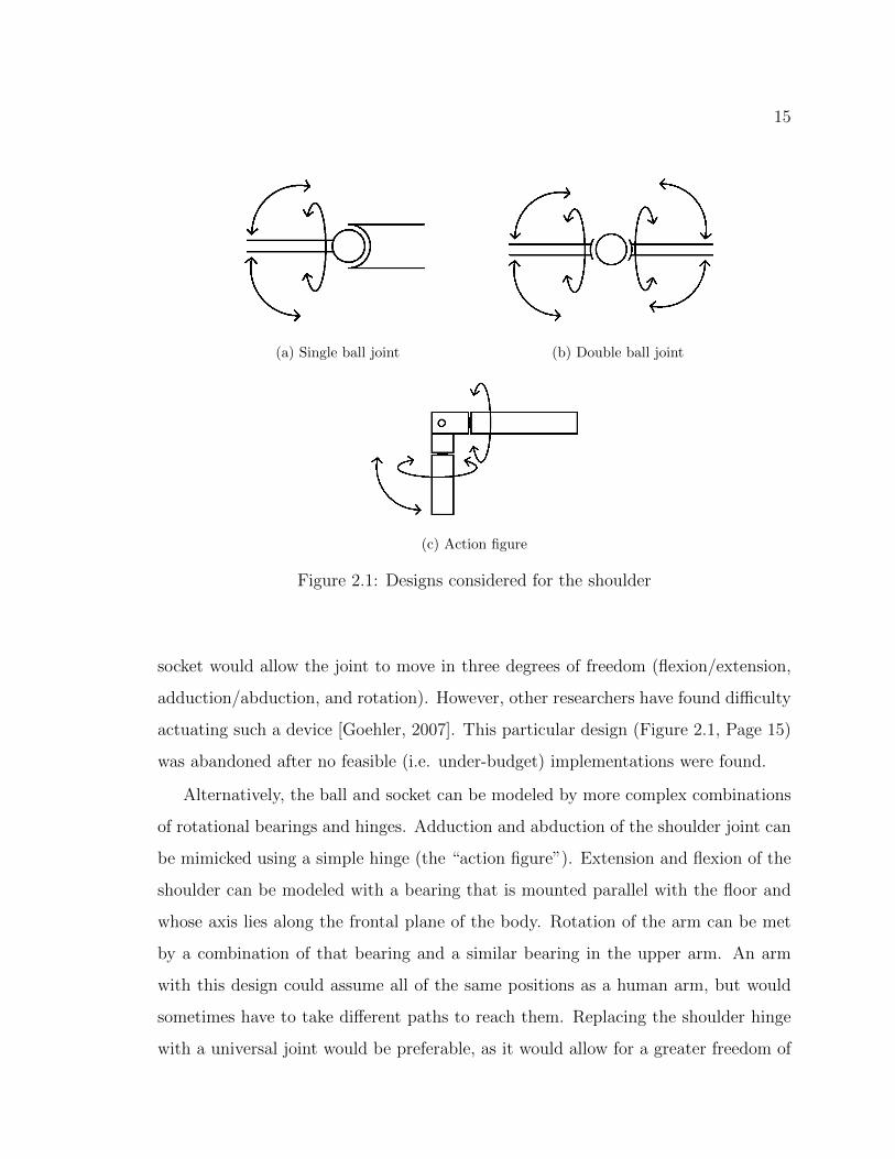
There are several options for the design of a biomimetic shoulder joint. The human
shoulder (Figure 1.4a, Page 7) is effectively a ball and socket. A mechanical ball and
15
(a) Single ball joint (b) Double ball joint
(c) Action figure
Figure 2.1: Designs considered for the shoulder
socket would allow the joint to move in three degrees of freedom (flexion/extension,
adduction/abduction, and rotation). However, other researchers have found difficulty
actuating such a device [Goehler, 2007]. This particular design (Figure 2.1, Page 15)
was abandoned after no feasible (i.e. under-budget) implementations were found.
Alternatively, the ball and socket can be modeled by more complex combinations
of rotational bearings and hinges. Adduction and abduction of the shoulder joint can
be mimicked using a simple hinge (the “action figure”). Extension and flexion of the
shoulder can be modeled with a bearing that is mounted parallel with the floor and
whose axis lies along the frontal plane of the body. Rotation of the arm can be met
by a combination of that bearing and a similar bearing in the upper arm. An arm
with this design could assume all of the same positions as a human arm, but would
sometimes have to take different paths to reach them. Replacing the shoulder hinge
with a universal joint would be preferable, as it would allow for a greater freedom of
16
motion.
Another option considered was a cable-driven arm that would use a system of
weights and pulleys to provide resistance as per Miwa et al. [2004] or Agrawal and
Dubey [2009]. This arm would have easily customizable resistances, as the design
could draw upon currently existing technology in weight/fitness machines. Difficulties
would include routing cable through or around joints as well as the possibility of
changing lengths as the arm is placed into different positions. Though tempting, this
design was abandoned in favor of a design with simpler implementation.
More complex methods of modeling the human shoulder, such as THOR’s ability to
shrug, were unnecessary for a first approximation of human shoulder motion. Ideally,
the final design would perfectly mimic a human shoulder but, in the interests of cost
and feasibility, sacrifices were made.
The elbow and wrist are simple hinges while wrist rotation is taken care of by
a bearing in the forearm. Finally, while outside the scope of this project, it is also
worth noting that, with adjustments to the resistance, a set of joints that effectively
model the human arm could easily be mapped to the leg.
2.3 Design Selected
The design chosen for implementation takes inspiration from both the bearing/hinge
model and the cable-driven model. The forearm and upper arm both have bearings
to allow for interior and exterior rotation and are spring-loaded to provide resistance.
The shoulder is a combination of two sets of concentric bearings and a universal joint.
Flexion and extension resistance is provided by cabling and weights (much like a
standard weight machine). Resistance to adduction is not provided, but abduction
resistance is created by a spring connecting the upper arm and shoulder.
This design was chosen because of its simplicity and effectiveness. Further details,
as well as the rationale behind design decisions, can be found in the following two
sections.

17
Figure 2.2: Rendering of final design in SolidWorks
2.4 Design Details
The following section describes the function of various pieces of the dummy arm.
For detailed drawings, see Appendix A. For a discussion of design decisions, see the
following section of design considerations.
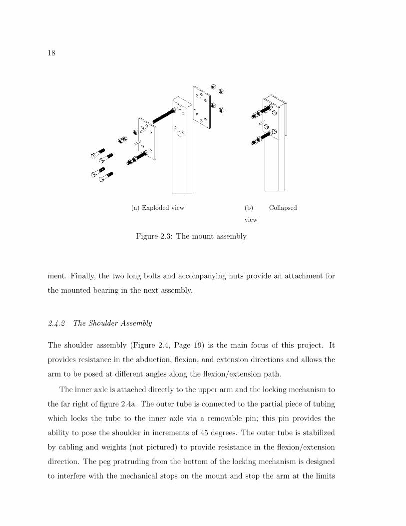
2.4.1 The Mount Assembly
The mounting portion of the device is a simple clamping mechanism, designed to
attach to a two-by-four (or similar) board. The two aluminum plates in figure 2.3,
page 18 are connected by an array of four bolts to ensure a solid mating. Further-
more, those plates act as the base for the entire assembly; though only one arm was
manufactured, another could easily be attached to the second plate. The two small,
protruding pegs are the mechanical stops that constrain extension and flexion move-
18
(a) Exploded view (b) Collapsed
view
Figure 2.3: The mount assembly
ment. Finally, the two long bolts and accompanying nuts provide an attachment for
the mounted bearing in the next assembly.
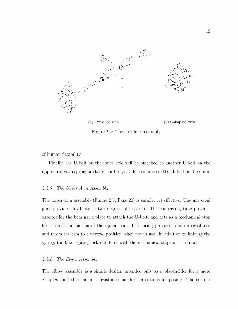
2.4.2 The Shoulder Assembly
The shoulder assembly (Figure 2.4, Page 19) is the main focus of this project. It
provides resistance in the abduction, flexion, and extension directions and allows the
arm to be posed at different angles along the flexion/extension path.
The inner axle is attached directly to the upper arm and the locking mechanism to
the far right of figure 2.4a. The outer tube is connected to the partial piece of tubing
which locks the tube to the inner axle via a removable pin; this pin provides the
ability to pose the shoulder in increments of 45 degrees. The outer tube is stabilized
by cabling and weights (not pictured) to provide resistance in the flexion/extension
direction. The peg protruding from the bottom of the locking mechanism is designed
to interfere with the mechanical stops on the mount and stop the arm at the limits
19
(a) Exploded view (b) Collapsed view
Figure 2.4: The shoulder assembly
of human flexibility.
Finally, the U-bolt on the inner axle will be attached to another U-bolt on the
upper arm via a spring or elastic cord to provide resistance in the abduction direction.
2.4.3 The Upper Arm Assembly
The upper arm assembly (Figure 2.5, Page 20) is simple, yet effective. The universal
joint provides flexibility in two degrees of freedom. The connecting tube provides
support for the bearing, a place to attach the U-bolt, and acts as a mechanical stop
for the rotation motion of the upper arm. The spring provides rotation resistance
and resets the arm to a neutral position when not in use. In addition to holding the
spring, the lower spring lock interferes with the mechanical stops on the tube.
2.4.4 The Elbow Assembly
The elbow assembly is a simple design, intended only as a placeholder for a more
complex joint that includes resistance and further options for posing. The current

20
(a) Exploded
view
(b) Collapsed
view
Figure 2.5: The upper arm assembly
design consists of two clevises attached to a simple piece of aluminum with stops that
will limit motion to roughly that of a human elbow. This is an unfinished piece, only
serving to connect the upper and lower arms together for the purposes of testing.
2.4.5 The Forearm Assembly
The forearm assembly (Figure 2.6, Page 21) is essentially the same as the upper arm,
with the addition of a simple hinge for the hand. Much like the elbow, the wrist is
an unfinished piece, only serving to provide a rough representation of a human hand.

21
(a) Exploded
view
(b) Collapsed
view
Figure 2.6: The forearm assembly
2.4.6 The Final Arm Assembly
The final arm assembly (Figure 2.7, Page 22) is a simple matter of combining all the
sub-assemblies.

22
(a) Exploded view (b) Collapsed view
Figure 2.7: The fully assembled arm
2.5 Design Considerations
In any design project decisions must be made between cost and function, or accuracy
and ease. This section provides details behind some of the compromises and deci-
sions made during this project. Improvements to the design will be discussed in the
following chapter.
2.5.1 Simplicity
One of the design requirements for this project was simplicity, both in design and
construction. For that reason, parts were either to be ordered off the shelf or designed
to be made with minimal difficulty in a machine shop. Because of this, a great deal
23
of effort went into adapting the design to match up with existing parts. Most of the
machined parts can be created in a short time on a lathe or milling machine.
Furthermore, the design is also quite modular. Most interfaces are locked with set
screws or are threaded connections. This allowed for ease in redesign or disassembly
after initial construction.
2.5.2 Weight
Original plans for the dummy called for mimicking the weight of a human arm. During
the investigation phase, however, it was discovered that the dead weight of an arm
(approximately 10 pounds) would require an excessive amount of spring or weight
resistance to control. Furthermore, in examining the arm of a Hybrid III crash test
dummy, it was discovered that manipulating the full dead weight of an arm can be
extremely difficult and tiring, while doing the same work with a human is not.
In light of these discoveries, the arm was made considerably lighter than 10 pounds.
Currently, it weighs approximately 2 lbs. This allows the joints to be controlled with
much weaker springs and less weight and makes for a much more pleasant experience
for the user.
2.5.3 Resistance
At the beginning of the design process, most of the resistance was planned around
the use of torsion springs. This would have allowed the joints to be compact and
self-contained. However, as the design process progressed, it became clear that the
only place such springs could be used appropriately was in the forearm and upper
arm. In those two positions, the springs provide resistance in both directions and
provide a natural neutral position. Convention dictates that torsion springs are only
supposed to be torqued in the direction of their winding, but in the case of the
prototype—because the loads and cycles are low—this should not pose a problem.
24
An elastic cord is used to constrain the ad/abduction of the shoulder. This was
done to reduce cost: the elastic acts as a customizable spring, meaning that it was
not necessary to purchase a dozen different springs of different lengths and sizes to
achieve the correct resistance. More important, however, was the decision to provide
resistance in only the abduction direction. This simplified the problem of adding
resistance to the shoulder joint by making use of the assumption that anyone whose
joints are being manipulated will pull their limbs toward their core (generally a wise
decision when it comes to fighting a joint lock).
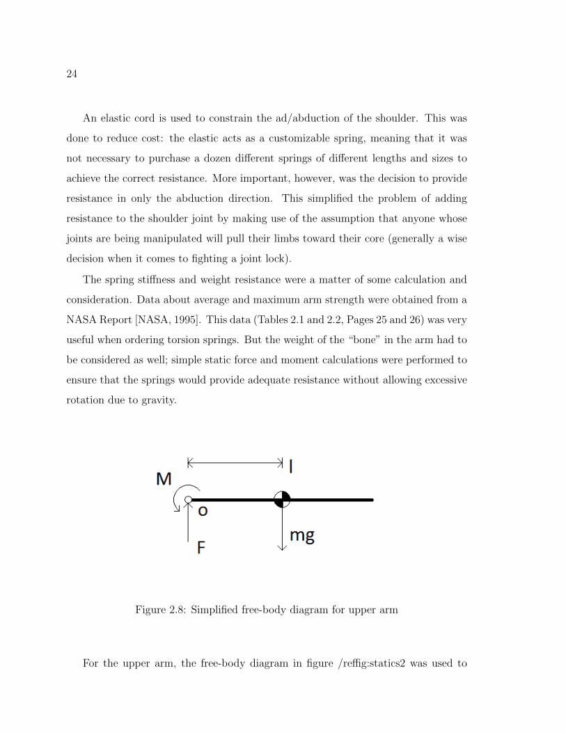
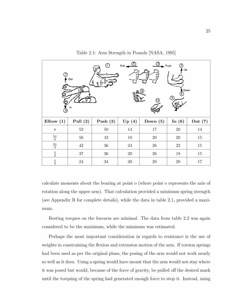
The spring stiffness and weight resistance were a matter of some calculation and
consideration. Data about average and maximum arm strength were obtained from a
NASA Report [NASA, 1995]. This data (Tables 2.1 and 2.2, Pages 25 and 26) was very
useful when ordering torsion springs. But the weight of the “bone” in the arm had to
be considered as well; simple static force and moment calculations were performed to
ensure that the springs would provide adequate resistance without allowing excessive
rotation due to gravity.
Figure 2.8: Simplified free-body diagram for upper arm
For the upper arm, the free-body diagram in figure /reffig:statics2 was used to
25
Table 2.1: Arm Strength in Pounds [NASA, 1995]
Elbow (1) Pull (2) Push (3) Up (4) Down (5) In (6) Out (7)
π 52 50 14 17 20 14
5π6 56 42 18 20 20 15
2π3 42 36 24 26 22 15
π2 37 36 20 26 18 15
π3 24 34 20 20 20 17
calculate moments about the bearing at point o (where point o represents the axis of
rotation along the upper arm). That calculation provided a minimum spring strength
(see Appendix B for complete details), while the data in table 2.1, provided a maxi-
mum.
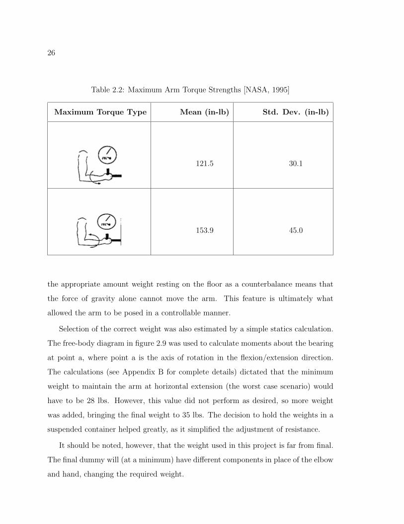
Resting torques on the forearm are minimal. The data from table 2.2 was again
considered to be the maximum, while the minimum was estimated.
Perhaps the most important consideration in regards to resistance is the use of
weights in constraining the flexion and extension motion of the arm. If torsion springs
had been used as per the original plans, the posing of the arm would not work nearly
so well as it does. Using a spring would have meant that the arm would not stay where
it was posed but would, because of the force of gravity, be pulled off the desired mark
until the torquing of the spring had generated enough force to stop it. Instead, using
26
Table 2.2: Maximum Arm Torque Strengths [NASA, 1995]
Maximum Torque Type Mean (in-lb) Std. Dev. (in-lb)
121.5 30.1
153.9 45.0
the appropriate amount weight resting on the floor as a counterbalance means that
the force of gravity alone cannot move the arm. This feature is ultimately what
allowed the arm to be posed in a controllable manner.
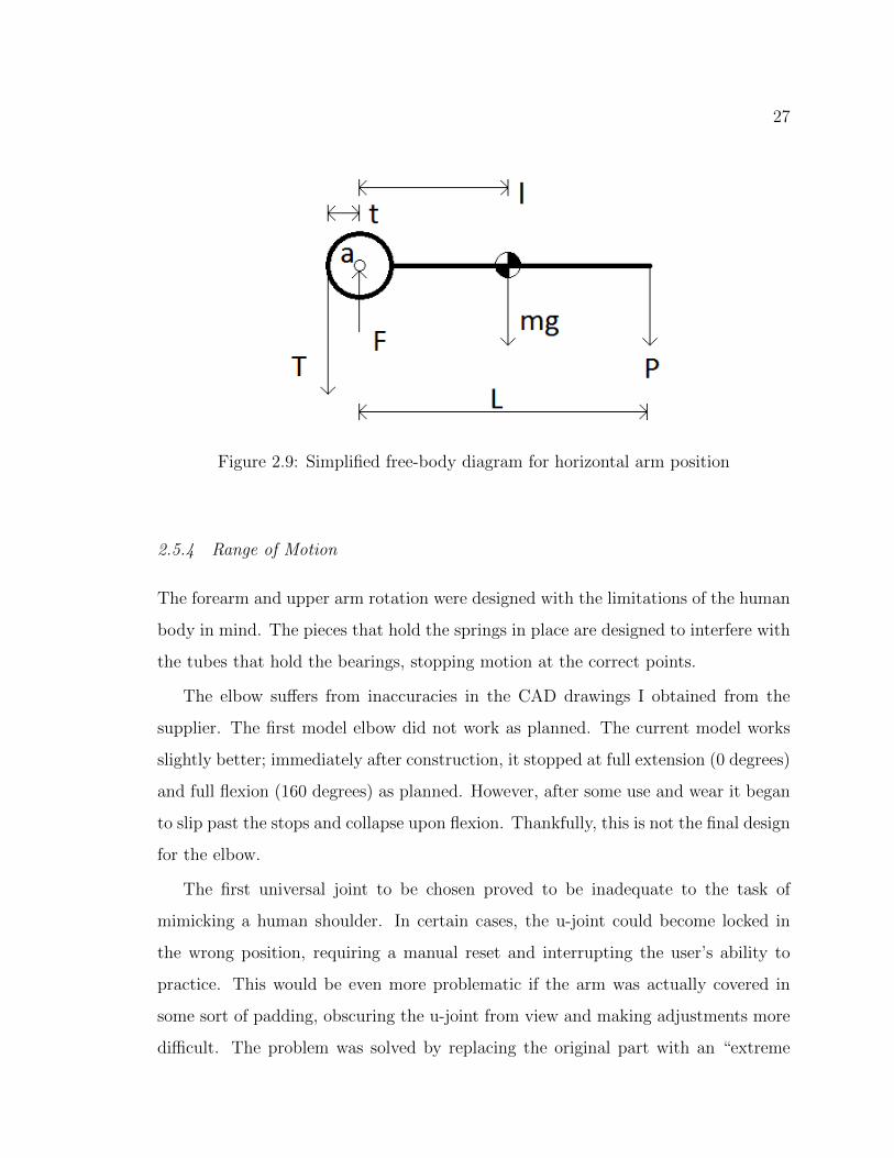
Selection of the correct weight was also estimated by a simple statics calculation.
The free-body diagram in figure 2.9 was used to calculate moments about the bearing
at point a, where point a is the axis of rotation in the flexion/extension direction.
The calculations (see Appendix B for complete details) dictated that the minimum
weight to maintain the arm at horizontal extension (the worst case scenario) would
have to be 28 lbs. However, this value did not perform as desired, so more weight
was added, bringing the final weight to 35 lbs. The decision to hold the weights in a
suspended container helped greatly, as it simplified the adjustment of resistance.
It should be noted, however, that the weight used in this project is far from final.
The final dummy will (at a minimum) have different components in place of the elbow
and hand, changing the required weight.
27
Figure 2.9: Simplified free-body diagram for horizontal arm position
2.5.4 Range of Motion
The forearm and upper arm rotation were designed with the limitations of the human
body in mind. The pieces that hold the springs in place are designed to interfere with
the tubes that hold the bearings, stopping motion at the correct points.
The elbow suffers from inaccuracies in the CAD drawings I obtained from the
supplier. The first model elbow did not work as planned. The current model works
slightly better; immediately after construction, it stopped at full extension (0 degrees)
and full flexion (160 degrees) as planned. However, after some use and wear it began
to slip past the stops and collapse upon flexion. Thankfully, this is not the final design
for the elbow.
The first universal joint to be chosen proved to be inadequate to the task of
mimicking a human shoulder. In certain cases, the u-joint could become locked in
the wrong position, requiring a manual reset and interrupting the user’s ability to
practice. This would be even more problematic if the arm was actually covered in
some sort of padding, obscuring the u-joint from view and making adjustments more
difficult. The problem was solved by replacing the original part with an “extreme

28
angle” universal joint that was designed to operate at much greater angles, giving it
more freedom to bend.
2.6 Summary
A review of design goals (Table 2.3) shows that all of the specified targets were met
by the final design. The next step was to build and test the prototype, to test the
success of the design.
Table 2.3: Design goals met
Design Requirement Met/Not Met
Minimize assembly Met
50th percentile male dimensions Met
Poseable, 3 positions Met
Easily poseable Met
Forearm rotates between wrist and elbow Met
Forearm rotates 90 degrees int./ext. Met
Forearm returns to neutral Met
Wrists and hand are in vertical position Met
Elbow 0 degree ext., 140 degree flex. Met
Upper arm rotates close to shoulder Met
Upper arm rotates 60 degrees int./ext. Met
Upper arm to return to neutral Met
Shoulder rotates to 180 degrees/-45 degrees Met
Shoulder to return to posed position Met

29
Chapter 3
THE PROTOTYPE
Following the completion of the final design, pieces that were not ordered off the
shelf were manufactured. The following section details the pieces that were machined.
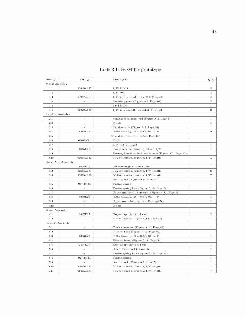
A full bill of materials (BOM) can be found in table 3.1, on page 43. Detailed
drawings of all manufactured parts can be found in Appendix A. All part numbers
refer to McMaster-Carr and can be found on their website (www.mcmaster.com).
Item numbers refer to table 3.1.
3.1 Manufacturing
All manufacturing was done in the University of Washington Integrated Learning
Factory (ILF). Although the ILF has several computer-controlled lathes and mills,
because of the relative simplicity of all the parts, most machining was done using
standard mills and lathes or hand held tools.
3.1.1 The Mount Assembly
The mount assembly is the simplest of all the parts of the prototype. It requires only
two identical machined pieces and several nuts and bolts.
Mounting Plates (Item 1.4)
The first step in machining the mounting plates (Figure 3.1, Page 30) was to cut a
large piece of 1/4” aluminum plate into two similarly sized pieces using a band saw.
The edges were then end-milled to be exactly the same size. The final step was to
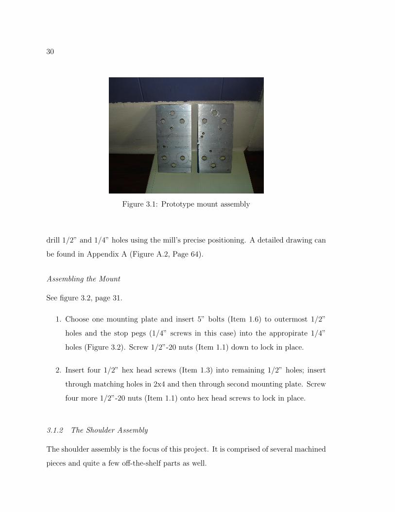
30
Figure 3.1: Prototype mount assembly
drill 1/2” and 1/4” holes using the mill’s precise positioning. A detailed drawing can
be found in Appendix A (Figure A.2, Page 64).
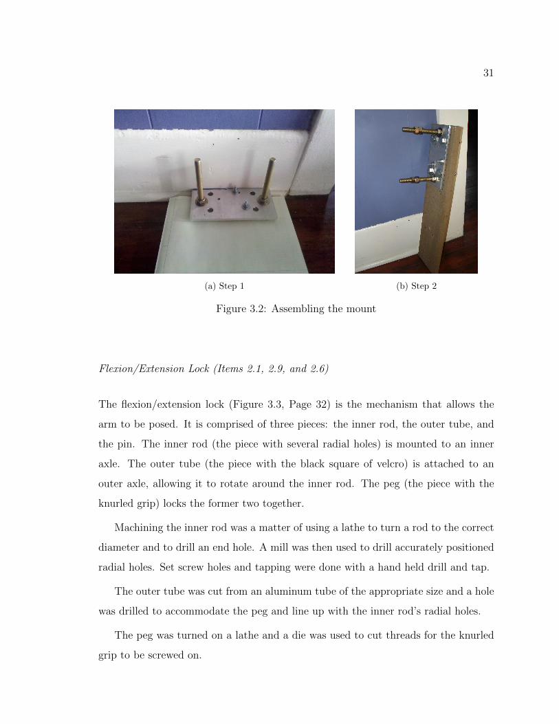
Assembling the Mount
See figure 3.2, page 31.
1. Choose one mounting plate and insert 5” bolts (Item 1.6) to outermost 1/2”
holes and the stop pegs (1/4” screws in this case) into the appropirate 1/4”
holes (Figure 3.2). Screw 1/2”-20 nuts (Item 1.1) down to lock in place.
2. Insert four 1/2” hex head screws (Item 1.3) into remaining 1/2” holes; insert
through matching holes in 2x4 and then through second mounting plate. Screw
four more 1/2”-20 nuts (Item 1.1) onto hex head screws to lock in place.
3.1.2 The Shoulder Assembly
The shoulder assembly is the focus of this project. It is comprised of several machined
pieces and quite a few off-the-shelf parts as well.
31
(a) Step 1 (b) Step 2
Figure 3.2: Assembling the mount
Flexion/Extension Lock (Items 2.1, 2.9, and 2.6)
The flexion/extension lock (Figure 3.3, Page 32) is the mechanism that allows the
arm to be posed. It is comprised of three pieces: the inner rod, the outer tube, and
the pin. The inner rod (the piece with several radial holes) is mounted to an inner
axle. The outer tube (the piece with the black square of velcro) is attached to an
outer axle, allowing it to rotate around the inner rod. The peg (the piece with the
knurled grip) locks the former two together.
Machining the inner rod was a matter of using a lathe to turn a rod to the correct
diameter and to drill an end hole. A mill was then used to drill accurately positioned
radial holes. Set screw holes and tapping were done with a hand held drill and tap.
The outer tube was cut from an aluminum tube of the appropriate size and a hole
was drilled to accommodate the peg and line up with the inner rod’s radial holes.
The peg was turned on a lathe and a die was used to cut threads for the knurled
grip to be screwed on.

32
Figure 3.3: Prototype flexion/extension lock
Figure 3.4: Prototype shoulder axle
Shoulder Axle (Item 2.3)
The narrower section of the shoulder axle (Figure 3.4, Page 32) was turned on a lathe
to allow it to fit through the smaller bearings in the shoulder. Two holes were later
drilled to accommodate the U-bolt.

33
Shoulder Tube (Item 2.5)
The shoulder tube can be seen in figure 3.3, page 32. The shoulder tube was a simple
matter of cutting a piece of aluminum tubing to size using a band saw and drilling
six set screw holes using a hand held drill and tap.
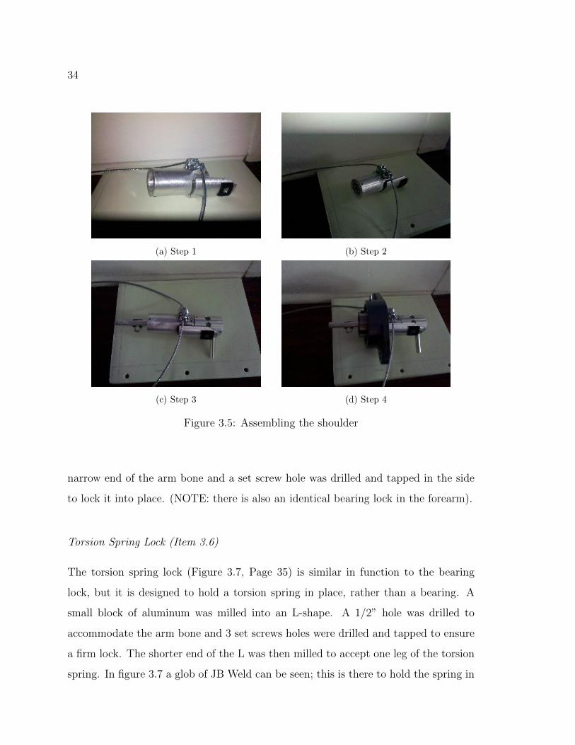
Assembling the Shoulder
See figure 3.5, page 34.
1. Attach the outer flexion/extension tube (Item 2.9) to shoulder tube (Item 2.5)
by welding or using epoxy (e.g. JB Weld) (cable attachments can also be added
at this point using Crosby clamps).
2. Insert bearing (Item 2.4) into either side of shoulder tube and secure using three
1/4” set screws (Item 2.10) apiece.
3. Insert shoulder axle (Item 2.3) into bearings. Insert narrow end of shoulder axle
into flexion/extension lock inner rod (Item 2.1). Secure using 6 1/3” set screws.
4. Insert shoulder tube into mounted bearing (Item 2.8), secure by tightening
bearing set screws.
3.1.3 The Upper Arm Assembly
The upper arm also requires several machined pieces.
Bearing Lock (Item 3.4)
The bearing lock (Figure 3.6, Page 35) is one of the simplest pieces in the entire
prototype. It is a 5/8”square of 1/4” aluminum plate, cut from the same stock as
the mounting plates. A 3/8” hole was drilled through the center to accommodate the
34
(a) Step 1 (b) Step 2
(c) Step 3 (d) Step 4
Figure 3.5: Assembling the shoulder
narrow end of the arm bone and a set screw hole was drilled and tapped in the side
to lock it into place. (NOTE: there is also an identical bearing lock in the forearm).
Torsion Spring Lock (Item 3.6)
The torsion spring lock (Figure 3.7, Page 35) is similar in function to the bearing
lock, but it is designed to hold a torsion spring in place, rather than a bearing. A
small block of aluminum was milled into an L-shape. A 1/2” hole was drilled to
accommodate the arm bone and 3 set screws holes were drilled and tapped to ensure
a firm lock. The shorter end of the L was then milled to accept one leg of the torsion
spring. In figure 3.7 a glob of JB Weld can be seen; this is there to hold the spring in

35
Figure 3.6: Prototype bearing lock
Figure 3.7: Prototype torsion spring lock
place. (NOTE: there is also an identical spring lock in the forearm).
Upper Arm Bone (Item 3.7)
The upper arm bone (Figure 3.8, Page 36) was a simple matter of cutting a piece of
1/2” diameter aluminum rod to length and lathing a small section of both ends down
to 3/8”. One end was threaded using a hand-held die.
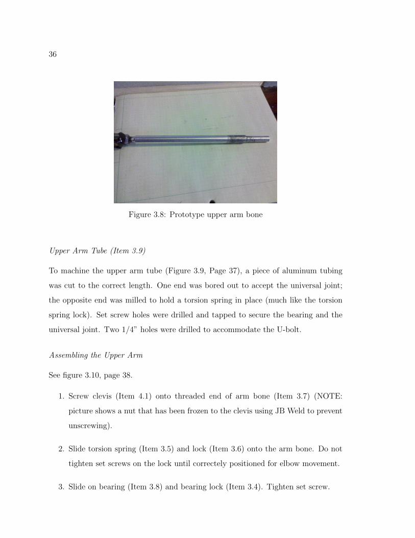
36
Figure 3.8: Prototype upper arm bone
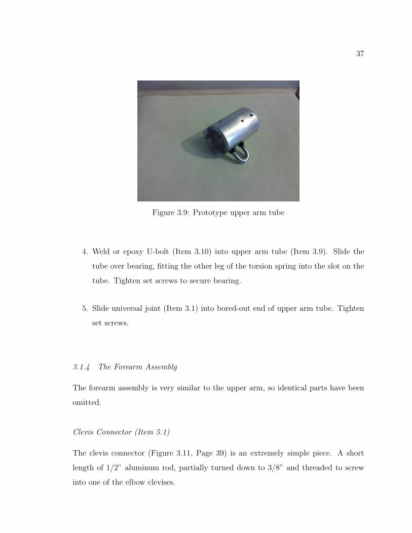
Upper Arm Tube (Item 3.9)
To machine the upper arm tube (Figure 3.9, Page 37), a piece of aluminum tubing
was cut to the correct length. One end was bored out to accept the universal joint;
the opposite end was milled to hold a torsion spring in place (much like the torsion
spring lock). Set screw holes were drilled and tapped to secure the bearing and the
universal joint. Two 1/4” holes were drilled to accommodate the U-bolt.
Assembling the Upper Arm
See figure 3.10, page 38.
1. Screw clevis (Item 4.1) onto threaded end of arm bone (Item 3.7) (NOTE:
picture shows a nut that has been frozen to the clevis using JB Weld to prevent
unscrewing).
2. Slide torsion spring (Item 3.5) and lock (Item 3.6) onto the arm bone. Do not
tighten set screws on the lock until correctely positioned for elbow movement.
3. Slide on bearing (Item 3.8) and bearing lock (Item 3.4). Tighten set screw.
37
Figure 3.9: Prototype upper arm tube
4. Weld or epoxy U-bolt (Item 3.10) into upper arm tube (Item 3.9). Slide the
tube over bearing, fitting the other leg of the torsion spring into the slot on the
tube. Tighten set screws to secure bearing.
5. Slide universal joint (Item 3.1) into bored-out end of upper arm tube. Tighten
set screws.
3.1.4 The Forearm Assembly
The forearm assembly is very similar to the upper arm, so identical parts have been
omitted.
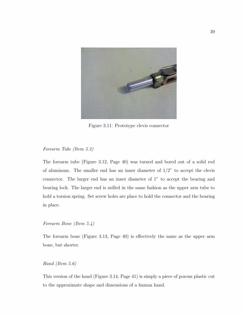
Clevis Connector (Item 5.1)
The clevis connector (Figure 3.11, Page 39) is an extremely simple piece. A short
length of 1/2” aluminum rod, partially turned down to 3/8” and threaded to screw
into one of the elbow clevises.

38
(a) Step 1 (b) Step 2
(c) Step 3 (d) Step 4
(e) Step 4
Figure 3.10: Assembling the upper arm
39
Figure 3.11: Prototype clevis connector
Forearm Tube (Item 5.2)
The forearm tube (Figure 3.12, Page 40) was turned and bored out of a solid rod
of aluminum. The smaller end has an inner diameter of 1/2” to accept the clevis
connector. The larger end has an inner diameter of 1” to accept the bearing and
bearing lock. The larger end is milled in the same fashion as the upper arm tube to
hold a torsion spring. Set screw holes are place to hold the connector and the bearing
in place.
Forearm Bone (Item 5.4)
The forearm bone (Figure 3.13, Page 40) is effectively the same as the upper arm
bone, but shorter.
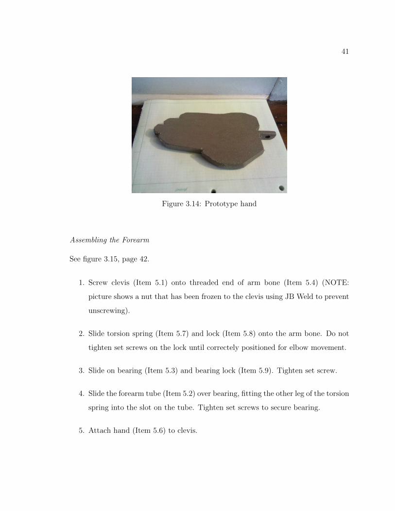
Hand (Item 5.6)
This version of the hand (Figure 3.14, Page 41) is simply a piece of porous plastic cut
to the approximate shape and dimensions of a human hand.

40
Figure 3.12: Prototype forearm tube
Figure 3.13: Prototype forearm bone
41
Figure 3.14: Prototype hand
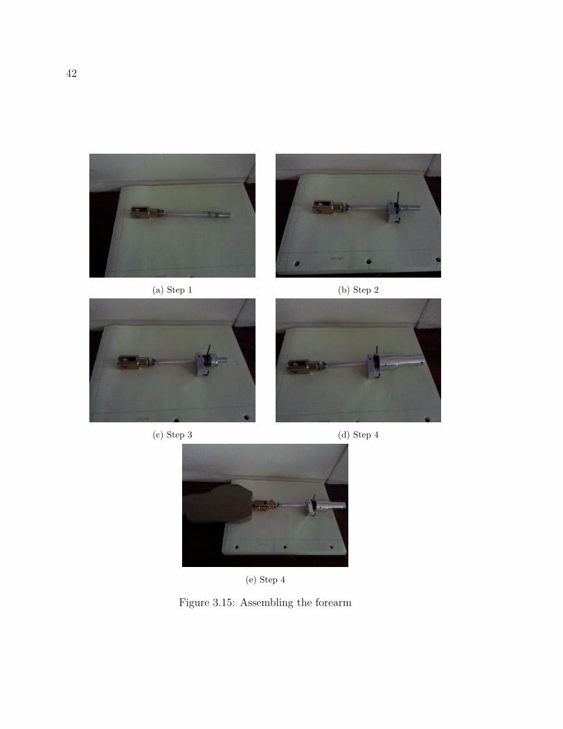
Assembling the Forearm
See figure 3.15, page 42.
1. Screw clevis (Item 5.1) onto threaded end of arm bone (Item 5.4) (NOTE:
picture shows a nut that has been frozen to the clevis using JB Weld to prevent
unscrewing).
2. Slide torsion spring (Item 5.7) and lock (Item 5.8) onto the arm bone. Do not
tighten set screws on the lock until correctely positioned for elbow movement.
3. Slide on bearing (Item 5.3) and bearing lock (Item 5.9). Tighten set screw.
4. Slide the forearm tube (Item 5.2) over bearing, fitting the other leg of the torsion
spring into the slot on the tube. Tighten set screws to secure bearing.
5. Attach hand (Item 5.6) to clevis.
42
(a) Step 1 (b) Step 2
(c) Step 3 (d) Step 4
(e) Step 4
Figure 3.15: Assembling the forearm
43
Table 3.1: BOM for prototype
Item # Part # Description Qty.
Mount Assembly
1.1 91845A145 1/2”-20 Nut 12
1.2 - 1/4” Peg 2
1.3 91247A358 1/2”-20 Hex Head Screw, 2 1/2” length 4
1.4 - Mounting plate (Figure A.2, Page 63) 2
1.5 - 2 x 4 board 1
1.6 92620A754 1/2”-20 Bolt, fully threaded, 5” length 2
Shoulder Assembly
2.1 - Flx/Ext lock, inner rod (Figure A.4, Page 67) 1
2.2 - U-bolt 1
2.3 - Shoulder axle (Figure A.5, Page 68) 1
2.4 6383K23 Roller bearing, ID = 3/8”, OD = 1” 2
2.5 - Shoulder Tube (Figure A.6, Page 69) 1
2.6 65035K81 Knob 1
2.7 - 3/8” rod, 2” length 1
2.8 6665K26 Flange mounted bearing, ID = 1 1/2” 1
2.9 - Flexion/Extension lock, outer tube (Figure A.7, Page 70) 1
2.10 92695A132 6-32 set screws, cone tip, 1/4” length 12
Upper Arm Assembly
3.1 6444K16 Extreme angle universal joint 1
3.2 92695A130 6-32 set screws, cone tip, 1/8” length 6
3.3 92695A132 6-32 set screws, cone tip, 1/4” length 7
3.4 - Bearing lock (Figure A.9, Page 73) 1
3.5 9271K113 Torsion spring 1
3.6 - Torsion spring lock (Figure A.10, Page 74) 1
3.7 - Upper arm bone, “humerus” (Figure A.11, Page 75) 1
3.8 6383K23 Roller bearing, ID = 3/8”, OD = 1” 1
3.9 - Upper arm tube (Figure A.12, Page 76) 1
3.10 - U-bolt 1
Elbow Assembly
4.1 2447K17 Easy-Adapt clevis rod end 2
4.2 - Elbow Linkage (Figure A.14, Page 73) 1
Forearm Assembly
5.1 - Clevis connector (Figure A.16, Page 82) 1
5.2 - Forearm tube (Figure A.17, Page 83) 1
5.3 6383K23 Roller bearing, ID = 3/8”, OD = 1” 1
5.4 - Forearm bone, (Figure A.18, Page 84) 1
5.5 2447K17 Easy-Adapt clevis rod end 1
5.6 - Hand (Figure A.19, Page 85) 1
5.7 - Torsion spring lock (Figure A.10, Page 74) 1
5.8 9271K113 Torsion spring 1
5.9 - Bearing lock (Figure A.9, Page 73) 1
5.10 92695A132 6-32 set screws, cone tip, 1/4” length 2
5.11 92695A130 6-32 set screws, cone tip, 1/8” length 7

44
3.2 Cabling
After manufacturing was complete it was necessary to attach the cable for the sus-
pended weights. The cabling was attached to the shoulder tube using two Crosby
bolts (Figure 3.16a, Page 44): the wire rope was clamped into the bolts and then the
ends of the bolts were set into holes on the tube. The ends of the cables were looped
around thimbles and secured with two more Crosby bolts (Figure 3.16b, Page 44).
Two oval threaded links were used to attach the looped ends to a container for the
weights.
(a) Cable attachment at shoulder (b) Cable loops
Figure 3.16: Cable attachments

45
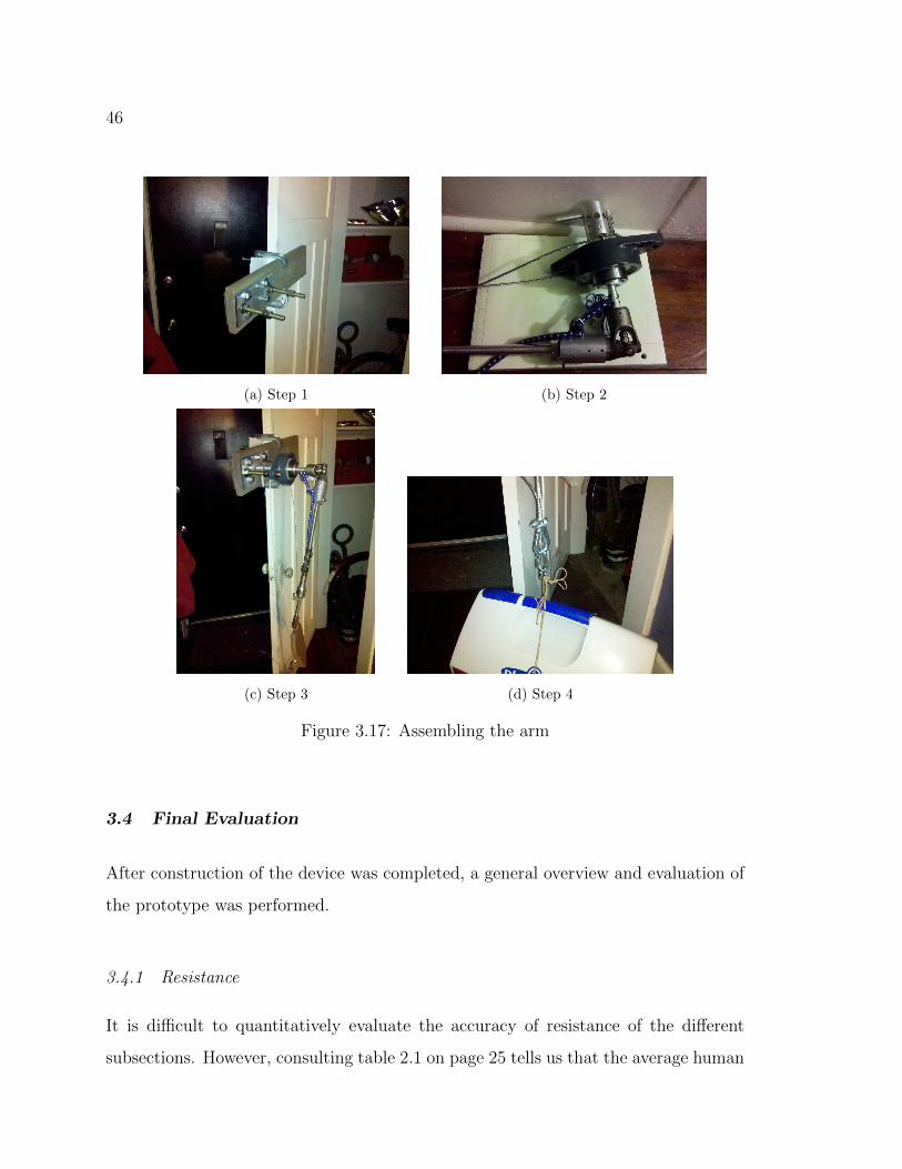
3.3 Final Assembly
See figure 3.17.
1. Use clamps to attach mount assembly to door.
2. Attach forearm and upper arm assemblies using the elbow assembly. Slide
universal joint on upper arm assembly onto shoulder axle.
3. Attach shoulder and arm assembly to mount using protruding bolts.
4. Connect cables to weighted container
46
(a) Step 1 (b) Step 2
(c) Step 3 (d) Step 4
Figure 3.17: Assembling the arm
3.4 Final Evaluation
After construction of the device was completed, a general overview and evaluation of
the prototype was performed.
3.4.1 Resistance
It is difficult to quantitatively evaluate the accuracy of resistance of the different
subsections. However, consulting table 2.1 on page 25 tells us that the average human
47
arm can exert 15-20 pounds in medial and lateral rotation of the shoulder. This
corresponds to a torque of approximately 200 in-lbs, requiring an extremely strong
spring. However, this represents the maximum reasonable resistance and, depending
how the data was gathered, may include the use of body weight. The spring chosen
for resistance offers only a tenth of that (20 in-lbs) and provides resistance that is
quite sufficient.
A similar pattern is seen in the forearm. Table 2.2 on page 2.2 shows that the
supination and pronation movements of the forearm can exert an average maximum
of 120-150 in-lbs. For simplicity’s sake, the same 20 in-lb spring was chosen for use
in the forearm, once again providing sufficient resistance.
As for flexion and extension resistance, Hughes et al. [1999] tells us that the human
arm can exert 400-700 in-lbs in this direction. Another statics calculation (Appendix
B) reveals that the use of 35 lbs of weight offers approximately 15 in-lbs of resistance.
While this would seem to be extremely low, using the device shows that this value
may actually be slightly too high for comfortable usage. However, nothing can be
done about it in this design.
Qualitatively, the resistance built into the arm works very well. Some joint locks
work better than others, but most of them can be practiced. Exceptions include locks
that require the opponent to bend at the waist or go to the ground, something that
cannot be helped until this design has a waist of its own.
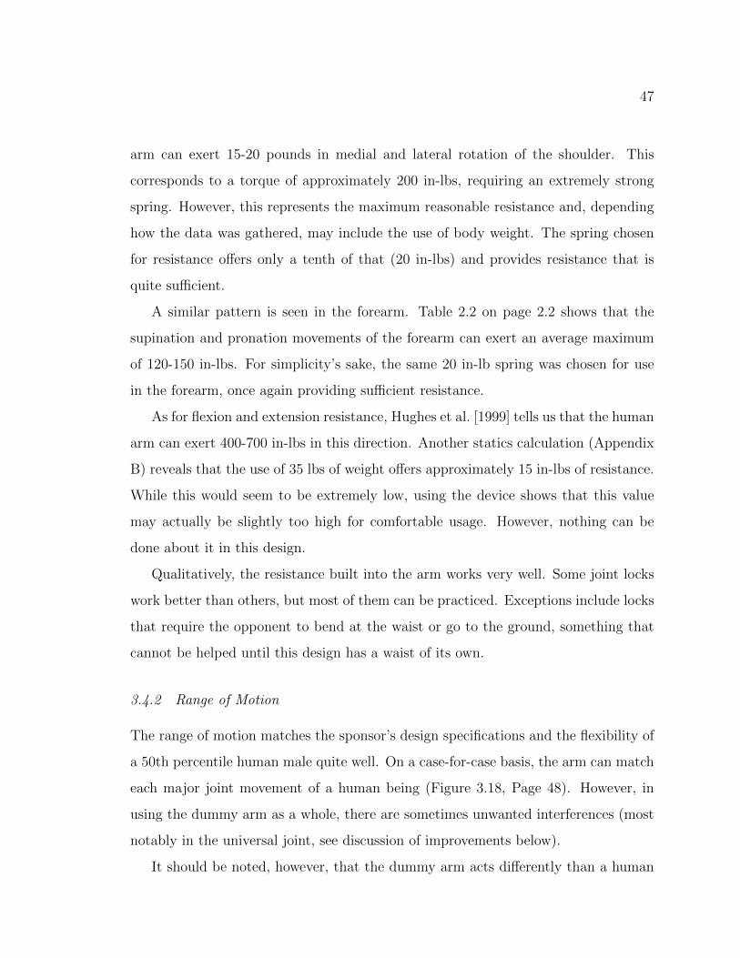
3.4.2 Range of Motion
The range of motion matches the sponsor’s design specifications and the flexibility of
a 50th percentile human male quite well. On a case-for-case basis, the arm can match
each major joint movement of a human being (Figure 3.18, Page 48). However, in
using the dummy arm as a whole, there are sometimes unwanted interferences (most
notably in the universal joint, see discussion of improvements below).
It should be noted, however, that the dummy arm acts differently than a human
48
(a) Shoulder flexion and extension
range of motion
(b) Shoulder adduction
and abduction range of
motion
(c) Shoulder internal and external rotation
range of motion
Figure 3.18: Shoulder range of motion
49
(a) Low position (b) Middle position (c) High posi-
tion
Figure 3.19: Poseable arm positions
arm when it reaches the extreme range of motion. A human arm will slowly stop
because of increasing resistance, or the rest of the body will move to compensate.
The dummy arm simply ceases to move as it runs into a mechanical stop. See the
improvements section for possible solutions.
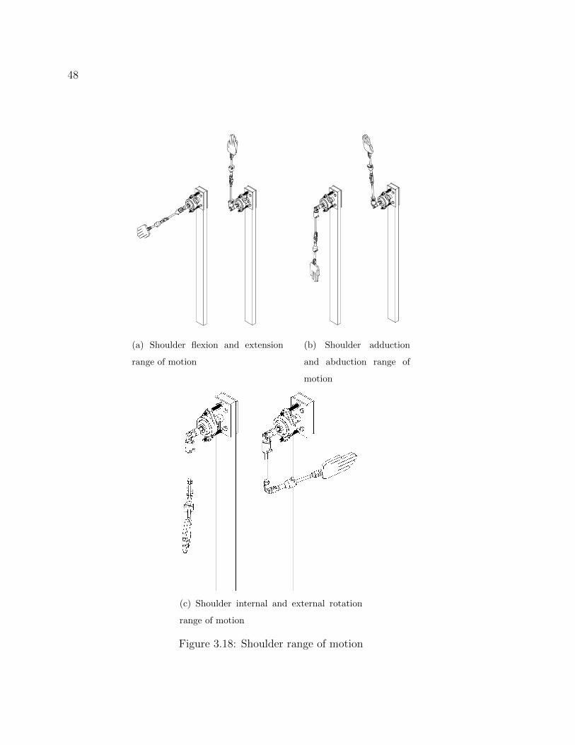
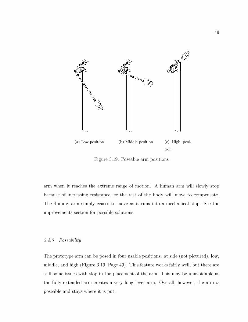
3.4.3 Poseability
The prototype arm can be posed in four usable positions: at side (not pictured), low,
middle, and high (Figure 3.19, Page 49). This feature works fairly well, but there are
still some issues with slop in the placement of the arm. This may be unavoidable as
the fully extended arm creates a very long lever arm. Overall, however, the arm is
poseable and stays where it is put.
50
3.5 Summary
In the end, the prototype functioned as expected; it offered a wide range of motion,
resistance to manipulation, and provides several poses. Some parts required more
machine work than originally intended but most of the design decisions proved to
be effective. The following chapter details possible improvements, future work to be
done, and conclusions drawn.
51
Chapter 4
CONCLUSIONS
4.1 Future Design Improvements
While the prototype functions well, there are some areas where improvement is
needed. This section details potential improvements for future models.
4.1.1 Fasteners and Modularity
Though extremely helpful in the prototyping phase, future designs should do away
with much of the modularity in this design. In some cases, the set screws have been
known to work themselves loose or prove insufficient to the task of holding pieces
together under normal operating loads. They can and should be replaced with spring
pins, bolts, welds, or other more permanent fasteners.
Also, the threaded clevis rod ends tend to (unsurprisingly) unscrew themselves
when the arm is twisted in the proper direction. The problem was solved using JB
Weld epoxy to freeze the rod ends in place, thus eliminating the usefulness of their
threads.
4.1.2 The Mount Assembly
The mount assembly performs adequately. However, depending on how future models
are marketed, this may need a redesign. One potential design is to sell standalone
arms that can be mounted to a standing or suspended heavy bag, removing the need
for designing an entire dummy. Furthermore, future models that incorporate the arm
design into a full dummy may even do away with the need for mounting of this type.
52
4.1.3 The Shoulder Assembly
While the shoulder assembly functions quite well, in future designs it might be desir-
able to use a lighter mounted bearing. The one currently in use works flawlessly, but
it is the heaviest part of shoulder by far. It could be replaced with something much
lighter and less expensive with a fairly simple redesign.
Another area of concern is the suspended weight system. While it works very well,
it is rather bulky and may be impractical in future designs. Possible solutions are
to make the cables much shorter and rest the weights within the “body” of the final
dummy. The weights may also cease to function as desired if the dummy is designed
to bend at the waist; this would change the angle of the arm relative to the ground
(changing the force due to gravity) and possibly change the length traveled by the
cable. To solve this problem the weights could be replaced with springs. This would
lead to more slop (lack of precision) in the positioning of the arms but eliminate
the problems surrounding the weights. The use of a damper in the flexion/extension
direction would help stability and should be considered for all joints using springs.
Alternatively, it may also be possible to route the cables through the waist joint.
This would minimizing the change in distance during a waist bend because the dis-
tance traveled by the cable would remain the same. The angle of the arm would
change, but the force exerted on the arm by gravity could never increase above the
maximum calculated for posing purposes. So, assuming the cable length remained
similar, a bend at the waist would have little-to-no effect on the positioning of the
arm, though there might be some changes in apparent resistance for the user.
Finally, after replacement of the original universal joint, the arm as a whole works
much better. However, there are still some issues with the functionality of the u-joint
itself. While it no longer gets completely stuck in the wrong position, it does not
move through all positions as smoothly as desired and sometimes inverts (returns
to a position 90 or 180 degrees from where it began). The best option for future
53
builds is most likely a custom-designed part that limits overall motion but retains the
flexibility of a universal joint.
4.1.4 The Upper Arm Assembly
The upper arm assembly works very well, though in future models it could be easily
modified to minimize the slop in rotation. This prototype was designed to accept
springs of varying sizes and, as a result, lacks precision. Now that an appropriate
spring has been chosen, the next model can use precision drilled holes instead of
roughly milled slots, greatly reducing the freedom of the spring to move and turn
without offering resistance.
Furthermore, in future designs it would be advisable to reinforce the stability
of the bearings. Using a single narrow bearing, while inexpensive, means that the
rotation motion is subject to a substantial amount of wobble and wear. One solution
would be to use two bearings of this type and space them farther apart. Alternatively,
a longer needle bearing might solve the problem as well. Either solution would require
minimal redesign.
4.1.5 The Elbow Assembly
The current elbow design has very little to offer: it provides no resistance and its
range of motion is not entirely correct. Future designs could offer quite a bit more
in the way of accuracy and usefulness. A design operating on similar principles to
the shoulder joint’s flexion and extension poseablity would be extremely desirable.
Such a design would provide resistance and allow posing of the forearm relative to
the upper arm.

54
4.1.6 The Forearm Assembly
The forearm suffers from the same problem of slop as the upper arm and would
benefit from the same solution. However, the wrist and hand are also in need of
improvement. The wrist joint could be greatly improved through the use of a ball
joint rod end. This would allow radial and ulnar deviation as well as flexion and
extension. Furthermore, the wrist also needs resistance which can most likely be
provided in the form of a torsion spring. A properly mounted torsion spring would
provide resistance in flexion/extension and also for both deviation directions.
Finally, there is the matter of the hand. A simple piece of crudely milled plas-
tic was used as a place holder. A biomimetic hand would be an extremely complex
subsystem to design and create. A simple alternative might be to use the hand of a
Hybrid III crash test dummy. This would provide a hand that meets the sponsor’s
specifications and do so without the need for more expensive research and develop-
ment.
4.1.7 Resistance and Range of Motion
As previously mentioned, the stopping of the arm joints at the end of their range of
motion is very unnatural. This might be mitigated by removing some of the stops
and allowing the increasing resistance of a spring to prevent further motion of the
arm, for a “soft” stop. Another option would be to add some kind of padding to the
stops, making for a softer, more organic limit.
The addition of dampers to the various joints should also be incorporated into
future designs. This would smooth the motion of the arm and prevent excessive
vibrations after manipulation is complete.
55
4.2 Future Work
Aside from improvements to the working of the current design, there are several other
paths of investigation that should be followed in the future.
4.2.1 Structural Analysis
One of the key requirements for a marketable dummy of this type will be its dura-
bility. A completed unit will have to withstand strikes from trained martial artists
and continue to function perfectly. It will need to retain its range of motion and re-
sistance despite rough treatment and continual use. Furthermore, one of the sponsor
requirements (Appendix C) requires the dummy to last through at least one million
cycles.
In light of these requirements, the final design of the dummy should undergo a
complete structural analysis. It should be designed to maximize the number of cycles
to failure.
Of particular concern are the cheap roller bearings in the upper arm and forearm.
The amount of wobble they allow could lead to serious damage under continuous
heavy use. It has already been suggested that they be replaced but whatever is
chosen must also undergo analysis for durability and be able to withstand the various
loads it will experience.
Furthermore, it may be desirable to use steel rather than aluminum for the final
design, as steel can be designed for infinite life while aluminum cannot. For a device
such as this, the main concern is most likely fatigue failure. Using narrow steel pipes
might be the best choice for the arm bones, offering similar strength and weight
to the aluminum rods currently in use. It’s unlikely that the forces experienced
during normal manipulation (or even during striking) would be enough to deform or
fracture the arm bones (though this should be confirmed). Rather it is the continuous
application of low-level force for a long period of time that is mostly likely to lead
56
to failure in the bones. The same can be said of the arm tubes (spring and bearing
holders) and shoulder axle and tube.
Any off-the-shelf parts should also be evaluated. Many parts can be found that
are certified for a certain lifetime. Failing that, failure/fatigue calculations can be
done to check out uncertified parts.
However, completing the required calculations will require gathering some of the
following data: striking force, force of manipulation, what constitutes minimal/normal/heavy
use, material properties, and part geometry. Material properties and part geometry
are easily obtainable, but the others will require some experimentation and research
all their own.
Striking force may be obtainable from literature but can also be measured in a
lab. Obtaining accurate data that covers a wide range of user sizes and strengths
would be ideal.
The forces applied during manipulation will have to be obtained via experiment.
See the section on instrumentation below. Furthermore, this data could be used to
confirm or refute the claim that the torsion springs in the upper arm and forearm will
last even when torqued against the direction of winding.
4.2.2 Instrumentation
Adding instrumentation to the device has been discussed since the very beginning of
the project. It was rejected as being too expensive and unnecessary for this design.
However, some of the possibilities bear mentioning.
For research purposes, strain gages would be extremely useful for the aforemen-
tioned lifetime calculations. Capturing the real strain while the device is in use would
be the best way to ensure a durable design. This would apply only to a development
prototype and would be completely unnecessary in a production model.
A force transducer of some kind might also be used for measuring the force of a
strike. Knowing the average force behind a kick or punch would also greatly aid in

57
designing for durability. Furthermore, this could also be useful in a final product,
giving feedback to a martial artist about his or her hitting power.
One other possibility would be to add sensors or electrical contacts to the joints
of the arm. When triggered, they would activate a light or tone that would notify the
user that pushing or pulling any farther might result in a dislocation or other serious
injury in a human arm. This would be an extremely useful tool, especially for law
enforcement where use of excessive force is often a problem.
4.2.3 Actuation
Using cables in the shoulder opens the door to actuation of the arm. Instead of
weight, the cables could be pulled by linear actuators or pulleys to control the arm.
This would most likely represent a dramatic increase in complexity and expense but
might also produce substantial benefits. An actuated arm would be able to perform
preprogrammed techniques (such as punches) and come even closer to replacing a
human training partner. However, such a device would require an almost complete
redesign of the resistance systems in the prototype.
4.2.4 Outer Covering
Whatever design is used in the end, its internal components must be covered, both
for their own protection and that of the user; rotating parts and joints offer many
pinch points for the unwary. Also, a correctly designed covering would increase the
realism of the arm, making it match human size more accurately. Such a covering
could be made of foam or rubber; it should be light (so as not to make the arm too
heavy), strong (for durability), and pliable (to mimic human skin).
One possible method of attaching the “skin” would be to fasten a tube or pipe
around the current design. It could be secured to the ends of the long bones. This
would allow the rotation of the forearm and upper arm to continue without impedi-
ment while providing a solid surface to mount the skin.

58
4.2.5 Completing the Dummy
The arm design in this paper is only a subsystem. Aside from further work on the arm
alone, there are several other pieces of the dummy that will need designing and testing.
It has already been noted that integrating the arm into a dummy with a mobile torso
may change the performance of the shoulder, and any such design should attempt to
minimize such effects to avoid a complete redesign of the shoulder. The final dummy
is also slated to include a head and flexing neck, as well as some sort of static legs.
Full design specifications for the dummy can be found in Appendix C.
4.3 Other Applications
While the arm design is intended for empty hand martial arts applications, it may
also have other uses. With modifications to the hand, the arms might also be useful
for armed martial arts such as fencing or kendo. Putting a sword into the hand of
the dummy would change the behavior of the arm, but would also open up another
market.
An arm of a similar type could also be used to train physical therapists in shoulder-
or elbow-specific techniques. In order for this to become reality, it is reasonable to
assume that the shoulder design would need to emulate the more advanced design of
the THOR (adding the scapular motions that were ignored for this project).
4.4 Summary
The project had it origins in attempting to replace a human training partner with a
dummy. Research into similar devices found that there was space for a dummy that
bridged the gap between striking and grappling dummies. For this thesis, the focus
was the shoulder; the rest of the arm was built for the express purpose of testing
the shoulder design. Previous work on humanoid shoulder devices revealed that most
were robotic or actuated designs; joint replacements were ruled out because their

59
intended application didn’t lend itself to the design goals of this project.
The prototype design was chosen for development after several other possibilities
proved to be either too complex or expensive. Inspiration for the prototype design
was drawn from some of the similar designs. Every effort was made to use inexpensive
and easy-to-assemble off-the-shelf parts. The design makes use of springs, elastic, and
weights to provide resistance and accurately matches the range of motion of a human
arm.
The prototype was constructed in a machine shop using lathes, mills, and other
common tools. Parts were machined as necessary for use with the purchased items.
Once assembled it became clear that several pieces, most notably the universal joint
were in need of modification or replacement. By design, the prototype was intended
to be easy to disassemble and reassemble so that changes and upgrades could easily
be integrated.
One assembly and construction were completed, the device was tested to ensure
that it’s range of motion and resistance were appropriate for its intended purpose.
The results of this testing are found in the previous section (“Future Design Improve-
ments”).
4.5 Conclusion
Despite flaws, this design represents a drastic improvement over the other products
available on the market today. As a proof-of-concept design, the prototype has per-
formed extremely well. It provides appropriate resistance for several types of joint
locks and offers a modicum of poseablity. While the arm is not ready to replace a
human training partner, it could be used to train certain techniques and to practice
them at full speed. Furthermore, if the above improvements are made, it will be that
much closer to being a marketable product. This project has successfully demon-
strated that a product mimicking the human arm can be created and used for martial
arts applications.
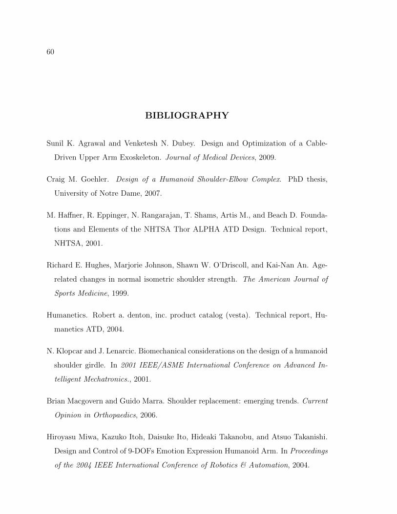
60
BIBLIOGRAPHY
Sunil K. Agrawal and Venketesh N. Dubey. Design and Optimization of a Cable-
Driven Upper Arm Exoskeleton. Journal of Medical Devices, 2009.
Craig M. Goehler. Design of a Humanoid Shoulder-Elbow Complex. PhD thesis,
University of Notre Dame, 2007.
M. Haffner, R. Eppinger, N. Rangarajan, T. Shams, Artis M., and Beach D. Founda-
tions and Elements of the NHTSA Thor ALPHA ATD Design. Technical report,
NHTSA, 2001.
Richard E. Hughes, Marjorie Johnson, Shawn W. O’Driscoll, and Kai-Nan An. Age-
related changes in normal isometric shoulder strength. The American Journal of
Sports Medicine, 1999.
Humanetics. Robert a. denton, inc. product catalog (vesta). Technical report, Hu-
manetics ATD, 2004.
N. Klopcar and J. Lenarcic. Biomechanical considerations on the design of a humanoid
shoulder girdle. In 2001 IEEE/ASME International Conference on Advanced In-
telligent Mechatronics., 2001.
Brian Macgovern and Guido Marra. Shoulder replacement: emerging trends. Current
Opinion in Orthopaedics, 2006.
Hiroyasu Miwa, Kazuko Itoh, Daisuke Ito, Hideaki Takanobu, and Atsuo Takanishi.
Design and Control of 9-DOFs Emotion Expression Humanoid Arm. In Proceedings
of the 2004 IEEE International Conference of Robotics & Automation, 2004.

61
NASA. Man-systems integration standards, revision b. Technical report, NASA,
1995.
NHTSA. Thor advanced crash test dummy. Technical report, NHTSA, 2011.
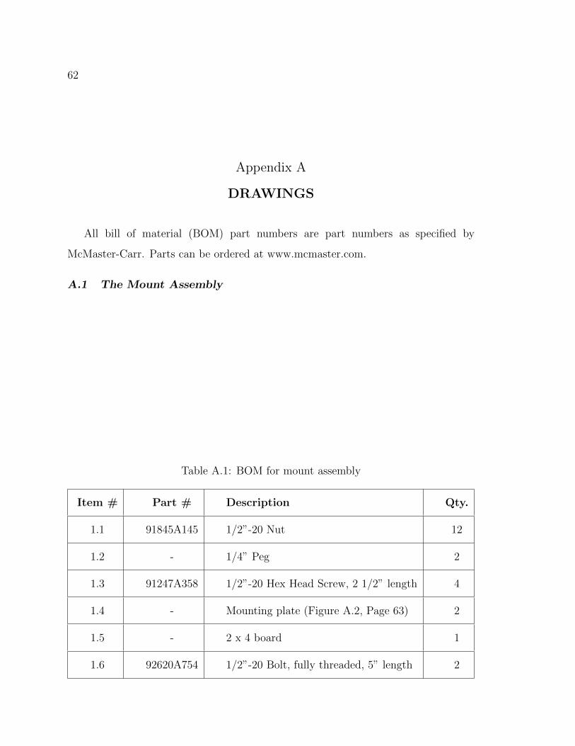
62
Appendix A
DRAWINGS
All bill of material (BOM) part numbers are part numbers as specified by
McMaster-Carr. Parts can be ordered at www.mcmaster.com.
A.1 The Mount Assembly
Table A.1: BOM for mount assembly
Item # Part # Description Qty.
1.1 91845A145 1/2”-20 Nut 12
1.2 - 1/4” Peg 2
1.3 91247A358 1/2”-20 Hex Head Screw, 2 1/2” length 4
1.4 - Mounting plate (Figure A.2, Page 63) 2
1.5 - 2 x 4 board 1
1.6 92620A754 1/2”-20 Bolt, fully threaded, 5” length 2
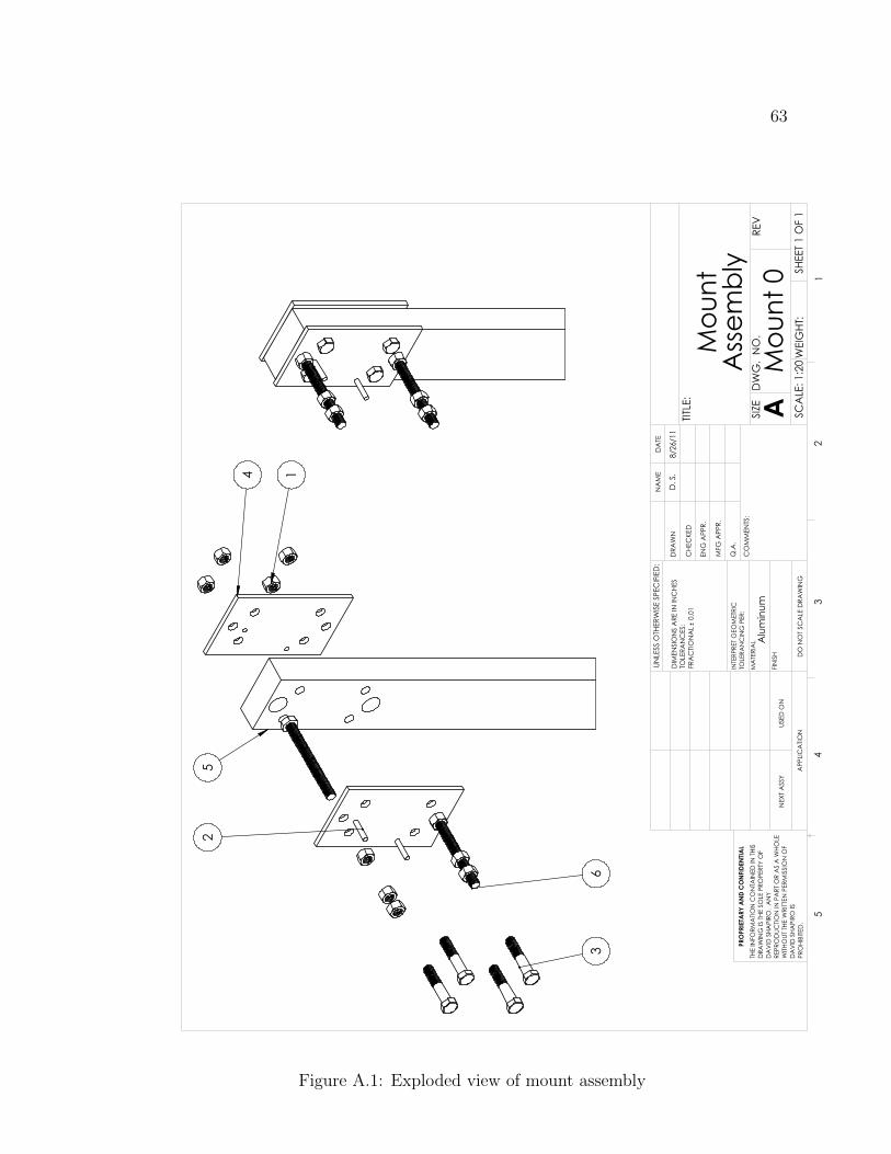
63
25
4 1
63
Mou
ntA
ssem
bly
DO
NO
T SC
ALE
DRA
WIN
G
Mou
nt 0 SH
EET 1
OF
1
8/26
/11
D. S
.
UNLE
SS O
THER
WIS
E SP
ECIF
IED
:
SCA
LE: 1
:20
WEI
GHT
:
REV
DW
G.
NO
.
ASIZE
TITLE
:
NA
ME
DA
TE
CO
MM
ENTS
:
Q.A
.
MFG
APP
R.
ENG
APP
R.
CHE
CKE
D
DRA
WN
Alu
min
umFI
NIS
H
MA
TERI
AL
INTE
RPRE
T G
EOM
ETRI
CTO
LERA
NC
ING
PER
:
DIM
ENSI
ON
S A
RE IN
INC
HES
TOLE
RAN
CES
:FR
AC
TION
AL
0.0
1
APP
LICA
TION
USED
ON
NEX
T A
SSY
PRO
PRIE
TARY
AN
D C
ON
FIDE
NTIA
LTH
E IN
FORM
ATIO
N C
ON
TAIN
ED IN
THI
SD
RAW
ING
IS T
HE S
OLE
PRO
PERT
Y O
FD
AV
ID S
HAPI
RO.
AN
Y RE
PRO
DUC
TION
IN P
ART
OR
AS
A W
HOLE
WITH
OUT
THE
WRI
TTEN
PER
MIS
SIO
N O
FD
AV
ID S
HAPI
RO IS
PR
OHI
BITE
D.
54
32
1
Figure A.1: Exploded view of mount assembly

64
.500
X6
.250
X2
4.00
0
7.00
0
0
.664
1.500
5.500
6.336
2.263
0
1.00
0
2.00
0
3.00
0
2.25
0
3.59
1
Mou
ting
Plat
e
DO
NO
T SC
ALE
DRA
WIN
G
Mou
nt 1 SH
EET 1
OF
1
8/26
/11
D. S
.
UNLE
SS O
THER
WIS
E SP
ECIF
IED
:
SCA
LE: 1
:2W
EIG
HT:
REV
DW
G.
NO
.
ASIZE
TITLE
:
NA
ME
DA
TE
CO
MM
ENTS
:
Q.A
.
MFG
APP
R.
ENG
APP
R.
CHE
CKE
D
DRA
WN
Alu
min
umFI
NIS
H
MA
TERI
AL
INTE
RPRE
T G
EOM
ETRI
CTO
LERA
NC
ING
PER
:
DIM
ENSI
ON
S A
RE IN
INC
HES
TOLE
RAN
CES
:FR
AC
TION
AL
0.0
1
APP
LICA
TION
USED
ON
NEX
T A
SSY
PRO
PRIE
TARY
AN
D C
ON
FIDE
NTIA
LTH
E IN
FORM
ATIO
N C
ON
TAIN
ED IN
THI
SD
RAW
ING
IS T
HE S
OLE
PRO
PERT
Y O
FD
AV
ID S
HAPI
RO.
AN
Y RE
PRO
DUC
TION
IN P
ART
OR
AS
A W
HOLE
WITH
OUT
THE
WRI
TTEN
PER
MIS
SIO
N O
FD
AV
ID S
HAPI
RO IS
PR
OHI
BITE
D.
54
32
1
Figure A.2: Part drawing of mounting plate

65
A.2 The Shoulder Assembly
Table A.2: BOM for shoulder assembly
Item # Part # Description Qty.
2.1 - Flx/Ext lock, inner rod (Figure A.4, Page 67) 1
2.2 - U-bolt 1
2.3 - Shoulder axle (Figure A.5, Page 68) 1
2.4 6383K23 Roller bearing, ID = 3/8”, OD = 1” 2
2.5 - Shoulder Tube (Figure A.6, Page 69) 1
2.6 65035K81 Knob 1
2.7 - 3/8” rod, 2” length 1
2.8 6665K26 Flange mounted bearing, ID = 1 1/2” 1
2.9 - Flx/Ext lock, outer tube (Figure A.7, Page 70) 1
2.10 92695A132 6-32 set screws, cone tip, 1/4” length 12
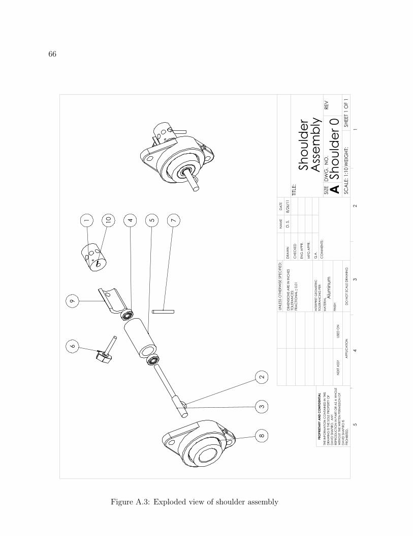
66
69
1 10 4 5 7
23
8
Shou
lder
Ass
embl
y
DO
NO
T SC
ALE
DRA
WIN
G
Shou
lder
0 SHEE
T 1 O
F 1
8/26
/11
D. S
.
UNLE
SS O
THER
WIS
E SP
ECIF
IED
:
SCA
LE: 1
:10
WEI
GHT
:
REV
DW
G.
NO
.
ASIZE
TITLE
:
NA
ME
DA
TE
CO
MM
ENTS
:
Q.A
.
MFG
APP
R.
ENG
APP
R.
CHE
CKE
D
DRA
WN
Alu
min
umFI
NIS
H
MA
TERI
AL
INTE
RPRE
T G
EOM
ETRI
CTO
LERA
NC
ING
PER
:
DIM
ENSI
ON
S A
RE IN
INC
HES
TOLE
RAN
CES
:FR
AC
TION
AL
0.0
1
APP
LICA
TION
USED
ON
NEX
T A
SSY
PRO
PRIE
TARY
AN
D C
ON
FIDE
NTIA
LTH
E IN
FORM
ATIO
N C
ON
TAIN
ED IN
THI
SD
RAW
ING
IS T
HE S
OLE
PRO
PERT
Y O
FD
AV
ID S
HAPI
RO.
AN
Y RE
PRO
DUC
TION
IN P
ART
OR
AS
A W
HOLE
WITH
OUT
THE
WRI
TTEN
PER
MIS
SIO
N O
FD
AV
ID S
HAPI
RO IS
PR
OHI
BITE
D.
54
32
1
Figure A.3: Exploded view of shoulder assembly
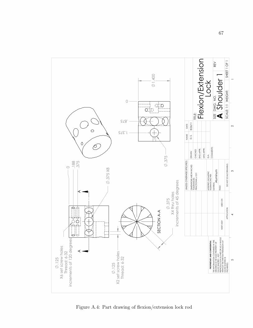
67
1.40
0
.375
0
.875
1.375
.375
X8
.125
X6
set s
crew
hol
esTh
read
: 6-3
2in
crem
ents
of 1
20 d
egre
es
.125
X2
set s
crew
hol
esTh
read
: 6-3
2
0 .188
.375
AA
.375
X4
thru
hol
esin
crem
ents
of 4
5 d
egre
es
SEC
TION
A-A
Flexio
n/Ex
tens
ion
Lock
DO
NO
T SC
ALE
DRA
WIN
G
Shou
lder
1 SHEE
T 1 O
F 1
8/26
/11
D. S
.
UNLE
SS O
THER
WIS
E SP
ECIF
IED
:
SCA
LE: 1
:1W
EIG
HT:
REV
DW
G.
NO
.
ASIZE
TITLE
:
NA
ME
DA
TE
CO
MM
ENTS
:
Q.A
.
MFG
APP
R.
ENG
APP
R.
CHE
CKE
D
DRA
WN
Alu
min
umFI
NIS
H
MA
TERI
AL
INTE
RPRE
T G
EOM
ETRI
CTO
LERA
NC
ING
PER
:
DIM
ENSI
ON
S A
RE IN
INC
HES
TOLE
RAN
CES
:FR
AC
TION
AL
0.0
1
APP
LICA
TION
USED
ON
NEX
T A
SSY
PRO
PRIE
TARY
AN
D C
ON
FIDE
NTIA
LTH
E IN
FORM
ATIO
N C
ON
TAIN
ED IN
THI
SD
RAW
ING
IS T
HE S
OLE
PRO
PERT
Y O
FD
AV
ID S
HAPI
RO.
AN
Y RE
PRO
DUC
TION
IN P
ART
OR
AS
A W
HOLE
WITH
OUT
THE
WRI
TTEN
PER
MIS
SIO
N O
FD
AV
ID S
HAPI
RO IS
PR
OHI
BITE
D.
54
32
1
Figure A.4: Part drawing of flexion/extension lock rod

68
.500
5.62
5
.375
3.62
5
Shou
lder
Axle
DO
NO
T SC
ALE
DRA
WIN
G
Shou
lder
2 SHEE
T 1 O
F 1
8/26
/11
D. S
.
UNLE
SS O
THER
WIS
E SP
ECIF
IED
:
SCA
LE: 1
:2W
EIG
HT:
REV
DW
G.
NO
.
ASIZE
TITLE
:
NA
ME
DA
TE
CO
MM
ENTS
:
Q.A
.
MFG
APP
R.
ENG
APP
R.
CHE
CKE
D
DRA
WN
Alu
min
umFI
NIS
H
MA
TERI
AL
INTE
RPRE
T G
EOM
ETRI
CTO
LERA
NC
ING
PER
:
DIM
ENSI
ON
S A
RE IN
INC
HES
TOLE
RAN
CES
:FR
AC
TION
AL
0.0
1
APP
LICA
TION
USED
ON
NEX
T A
SSY
PRO
PRIE
TARY
AN
D C
ON
FIDE
NTIA
LTH
E IN
FORM
ATIO
N C
ON
TAIN
ED IN
THI
SD
RAW
ING
IS T
HE S
OLE
PRO
PERT
Y O
FD
AV
ID S
HAPI
RO.
AN
Y RE
PRO
DUC
TION
IN P
ART
OR
AS
A W
HOLE
WITH
OUT
THE
WRI
TTEN
PER
MIS
SIO
N O
FD
AV
ID S
HAPI
RO IS
PR
OHI
BITE
D.
54
32
1
Figure A.5: Part drawing of shoulder axle

69
120.
00°
1.00
0
1.50
0
.125
X6 S
et sc
rew
hol
esTh
read
: 6-3
212
0 d
egre
e in
crem
ents
.125
.125
.188
X4 c
able
mou
nt h
oles
3.00
0
0 .250
.750
0
.563
.938
Shou
lder
Tub
e
DO
NO
T SC
ALE
DRA
WIN
G
Shou
lder
3 SHEE
T 1 O
F 1
8/26
/11
D. S
.
UNLE
SS O
THER
WIS
E SP
ECIF
IED
:
SCA
LE: 1
:1W
EIG
HT:
REV
DW
G.
NO
.
ASIZE
TITLE
:
NA
ME
DA
TE
CO
MM
ENTS
:
Q.A
.
MFG
APP
R.
ENG
APP
R.
CHE
CKE
D
DRA
WN
Alu
min
umFI
NIS
H
MA
TERI
AL
INTE
RPRE
T G
EOM
ETRI
CTO
LERA
NC
ING
PER
:
DIM
ENSI
ON
S A
RE IN
INC
HES
TOLE
RAN
CES
:FR
AC
TION
AL
0.0
1
APP
LICA
TION
USED
ON
NEX
T A
SSY
PRO
PRIE
TARY
AN
D C
ON
FIDE
NTIA
LTH
E IN
FORM
ATIO
N C
ON
TAIN
ED IN
THI
SD
RAW
ING
IS T
HE S
OLE
PRO
PERT
Y O
FD
AV
ID S
HAPI
RO.
AN
Y RE
PRO
DUC
TION
IN P
ART
OR
AS
A W
HOLE
WITH
OUT
THE
WRI
TTEN
PER
MIS
SIO
N O
FD
AV
ID S
HAPI
RO IS
PR
OHI
BITE
D.
54
32
1
Figure A.6: Part drawing of shoulder tube
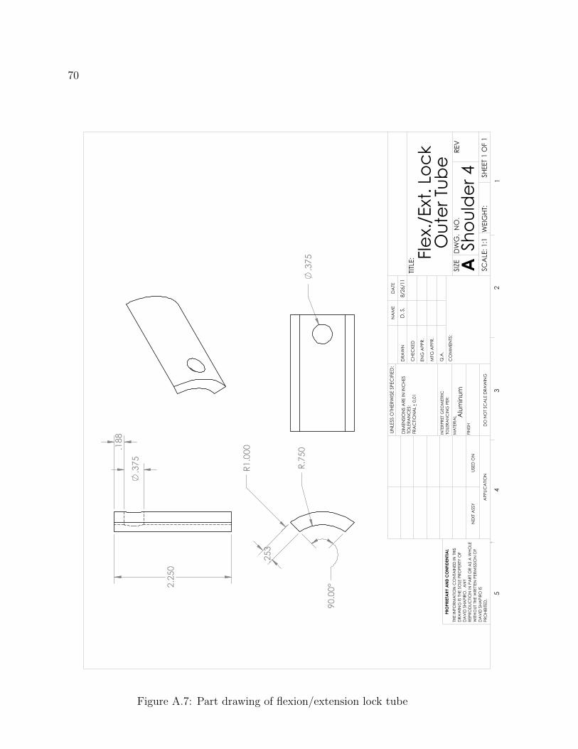
70
.253
90.0
0°
R1.0
00
R.75
0.3
75
2.25
0
.375
.188
Flex.
/Ext
. Loc
kO
uter
Tub
e
DO
NO
T SC
ALE
DRA
WIN
G
Shou
lder
4 SHEE
T 1 O
F 1
8/26
/11
D. S
.
UNLE
SS O
THER
WIS
E SP
ECIF
IED
:
SCA
LE: 1
:1W
EIG
HT:
REV
DW
G.
NO
.
ASIZE
TITLE
:
NA
ME
DA
TE
CO
MM
ENTS
:
Q.A
.
MFG
APP
R.
ENG
APP
R.
CHE
CKE
D
DRA
WN
Alu
min
umFI
NIS
H
MA
TERI
AL
INTE
RPRE
T G
EOM
ETRI
CTO
LERA
NC
ING
PER
:
DIM
ENSI
ON
S A
RE IN
INC
HES
TOLE
RAN
CES
:FR
AC
TION
AL
0.0
1
APP
LICA
TION
USED
ON
NEX
T A
SSY
PRO
PRIE
TARY
AN
D C
ON
FIDE
NTIA
LTH
E IN
FORM
ATIO
N C
ON
TAIN
ED IN
THI
SD
RAW
ING
IS T
HE S
OLE
PRO
PERT
Y O
FD
AV
ID S
HAPI
RO.
AN
Y RE
PRO
DUC
TION
IN P
ART
OR
AS
A W
HOLE
WITH
OUT
THE
WRI
TTEN
PER
MIS
SIO
N O
FD
AV
ID S
HAPI
RO IS
PR
OHI
BITE
D.
54
32
1
Figure A.7: Part drawing of flexion/extension lock tube
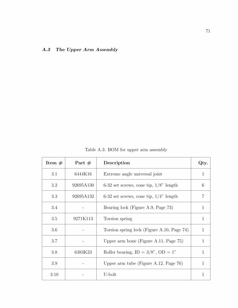
71
A.3 The Upper Arm Assembly
Table A.3: BOM for upper arm assembly
Item # Part # Description Qty.
3.1 6444K16 Extreme angle universal joint 1
3.2 92695A130 6-32 set screws, cone tip, 1/8” length 6
3.3 92695A132 6-32 set screws, cone tip, 1/4” length 7
3.4 - Bearing lock (Figure A.9, Page 73) 1
3.5 9271K113 Torsion spring 1
3.6 - Torsion spring lock (Figure A.10, Page 74) 1
3.7 - Upper arm bone (Figure A.11, Page 75) 1
3.8 6383K23 Roller bearing, ID = 3/8”, OD = 1” 1
3.9 - Upper arm tube (Figure A.12, Page 76) 1
3.10 - U-bolt 1

72
1 2 3 4 5 6 7
8910
Uppe
r Arm
Ass
embl
y
DO
NO
T SC
ALE
DRA
WIN
G
Uppe
r 0SH
EET 1
OF
1
8/26
/11
D. S
.
UNLE
SS O
THER
WIS
E SP
ECIF
IED
:
SCA
LE: 1
:5W
EIG
HT:
REV
DW
G.
NO
.
ASIZE
TITLE
:
NA
ME
DA
TE
CO
MM
ENTS
:
Q.A
.
MFG
APP
R.
ENG
APP
R.
CHE
CKE
D
DRA
WN
Alu
min
umFI
NIS
H
MA
TERI
AL
INTE
RPRE
T G
EOM
ETRI
CTO
LERA
NC
ING
PER
:
DIM
ENSI
ON
S A
RE IN
INC
HES
TOLE
RAN
CES
:FR
AC
TION
AL
0.0
1
APP
LICA
TION
USED
ON
NEX
T A
SSY
PRO
PRIE
TARY
AN
D C
ON
FIDE
NTIA
LTH
E IN
FORM
ATIO
N C
ON
TAIN
ED IN
THI
SD
RAW
ING
IS T
HE S
OLE
PRO
PERT
Y O
FD
AV
ID S
HAPI
RO.
AN
Y RE
PRO
DUC
TION
IN P
ART
OR
AS
A W
HOLE
WITH
OUT
THE
WRI
TTEN
PER
MIS
SIO
N O
FD
AV
ID S
HAPI
RO IS
PR
OHI
BITE
D.
54
32
1
Figure A.8: Exploded view of upper arm assembly
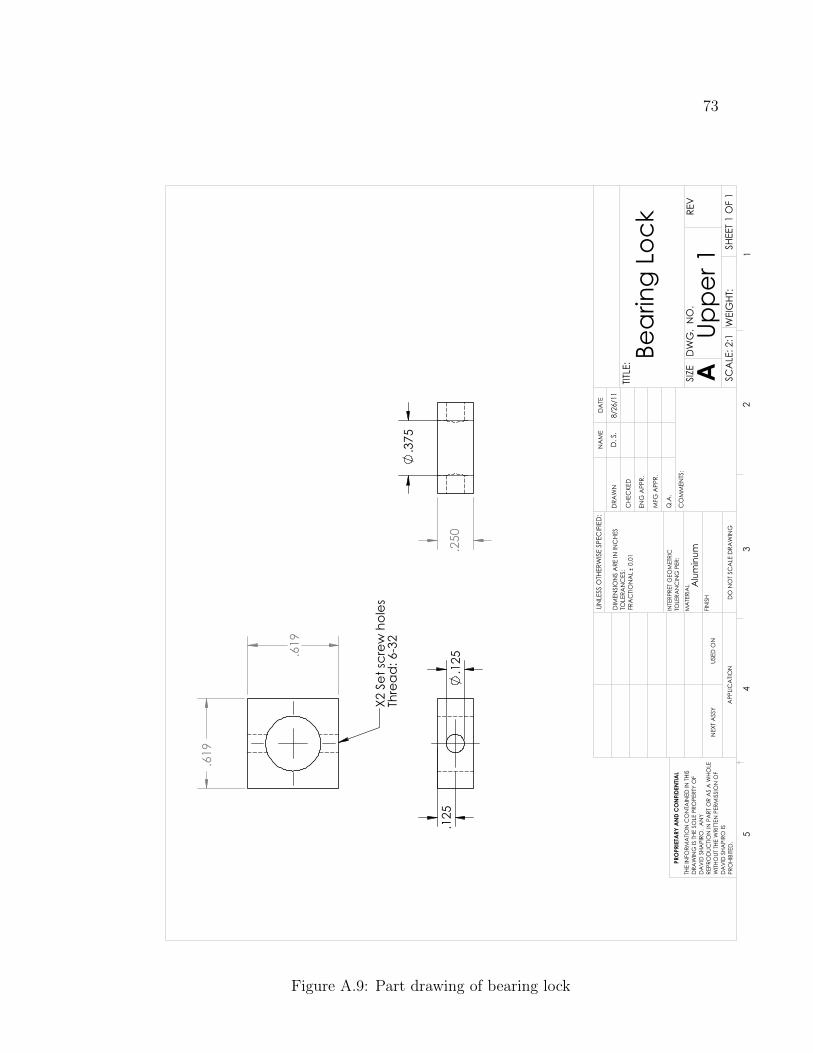
73
.125
.125
.375
.250
.619
.619
X2 S
et sc
rew
hol
es
Thre
ad: 6
-32
Bear
ing
Lock
DO
NO
T SC
ALE
DRA
WIN
G
Uppe
r 1SH
EET 1
OF
1
8/26
/11
D. S
.
UNLE
SS O
THER
WIS
E SP
ECIF
IED
:
SCA
LE: 2
:1W
EIG
HT:
REV
DW
G.
NO
.
ASIZE
TITLE
:
NA
ME
DA
TE
CO
MM
ENTS
:
Q.A
.
MFG
APP
R.
ENG
APP
R.
CHE
CKE
D
DRA
WN
Alu
min
umFI
NIS
H
MA
TERI
AL
INTE
RPRE
T G
EOM
ETRI
CTO
LERA
NC
ING
PER
:
DIM
ENSI
ON
S A
RE IN
INC
HES
TOLE
RAN
CES
:FR
AC
TION
AL
0.0
1
APP
LICA
TION
USED
ON
NEX
T A
SSY
PRO
PRIE
TARY
AN
D C
ON
FIDE
NTIA
LTH
E IN
FORM
ATIO
N C
ON
TAIN
ED IN
THI
SD
RAW
ING
IS T
HE S
OLE
PRO
PERT
Y O
FD
AV
ID S
HAPI
RO.
AN
Y RE
PRO
DUC
TION
IN P
ART
OR
AS
A W
HOLE
WITH
OUT
THE
WRI
TTEN
PER
MIS
SIO
N O
FD
AV
ID S
HAPI
RO IS
PR
OHI
BITE
D.
54
32
1
Figure A.9: Part drawing of bearing lock
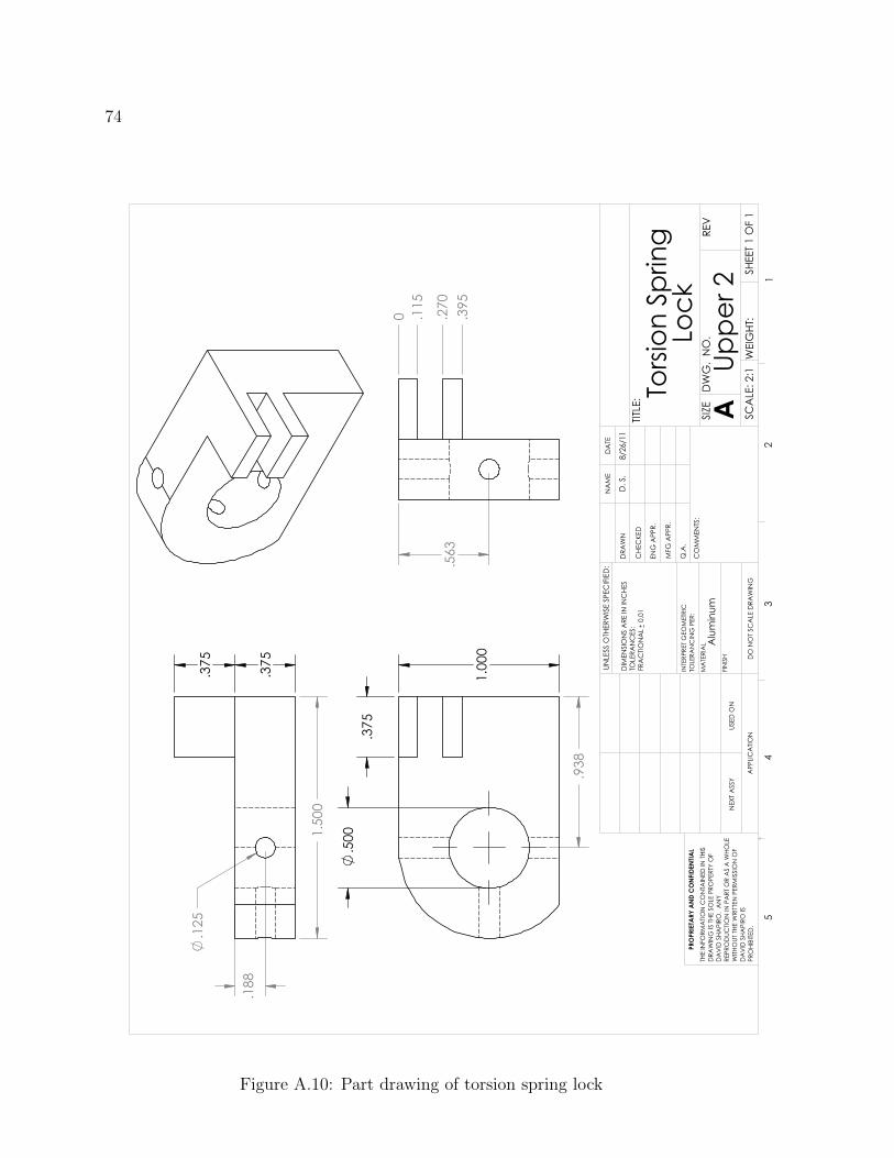
74
1.00
0
.375
.500
.938
.375
.375
.125
.188
1.50
0
.563
0 .115
.270
.395
Torsi
on S
prin
gLo
ck
DO
NO
T SC
ALE
DRA
WIN
G
Uppe
r 2SH
EET 1
OF
1
8/26
/11
D. S
.
UNLE
SS O
THER
WIS
E SP
ECIF
IED
:
SCA
LE: 2
:1W
EIG
HT:
REV
DW
G.
NO
.
ASIZE
TITLE
:
NA
ME
DA
TE
CO
MM
ENTS
:
Q.A
.
MFG
APP
R.
ENG
APP
R.
CHE
CKE
D
DRA
WN
Alu
min
umFI
NIS
H
MA
TERI
AL
INTE
RPRE
T G
EOM
ETRI
CTO
LERA
NC
ING
PER
:
DIM
ENSI
ON
S A
RE IN
INC
HES
TOLE
RAN
CES
:FR
AC
TION
AL
0.0
1
APP
LICA
TION
USED
ON
NEX
T A
SSY
PRO
PRIE
TARY
AN
D C
ON
FIDE
NTIA
LTH
E IN
FORM
ATIO
N C
ON
TAIN
ED IN
THI
SD
RAW
ING
IS T
HE S
OLE
PRO
PERT
Y O
FD
AV
ID S
HAPI
RO.
AN
Y RE
PRO
DUC
TION
IN P
ART
OR
AS
A W
HOLE
WITH
OUT
THE
WRI
TTEN
PER
MIS
SIO
N O
FD
AV
ID S
HAPI
RO IS
PR
OHI
BITE
D.
54
32
1
Figure A.10: Part drawing of torsion spring lock

75
.375
.500
9.40
0
1.50
01.
250
Uppe
r Arm
Bon
e,"H
umer
us"
DO
NO
T SC
ALE
DRA
WIN
G
Uppe
r 3SH
EET 1
OF
1
8/26
/11
D. S
.
UNLE
SS O
THER
WIS
E SP
ECIF
IED
:
SCA
LE: 1
:5W
EIG
HT:
REV
DW
G.
NO
.
ASIZE
TITLE
:
NA
ME
DA
TE
CO
MM
ENTS
:
Q.A
.
MFG
APP
R.
ENG
APP
R.
CHE
CKE
D
DRA
WN
Alu
min
umFI
NIS
H
MA
TERI
AL
INTE
RPRE
T G
EOM
ETRI
CTO
LERA
NC
ING
PER
:
DIM
ENSI
ON
S A
RE IN
INC
HES
TOLE
RAN
CES
:FR
AC
TION
AL
0.0
1
APP
LICA
TION
USED
ON
NEX
T A
SSY
PRO
PRIE
TARY
AN
D C
ON
FIDE
NTIA
LTH
E IN
FORM
ATIO
N C
ON
TAIN
ED IN
THI
SD
RAW
ING
IS T
HE S
OLE
PRO
PERT
Y O
FD
AV
ID S
HAPI
RO.
AN
Y RE
PRO
DUC
TION
IN P
ART
OR
AS
A W
HOLE
WITH
OUT
THE
WRI
TTEN
PER
MIS
SIO
N O
FD
AV
ID S
HAPI
RO IS
PR
OHI
BITE
D.
54
32
1
Figure A.11: Part drawing of upper arm bone
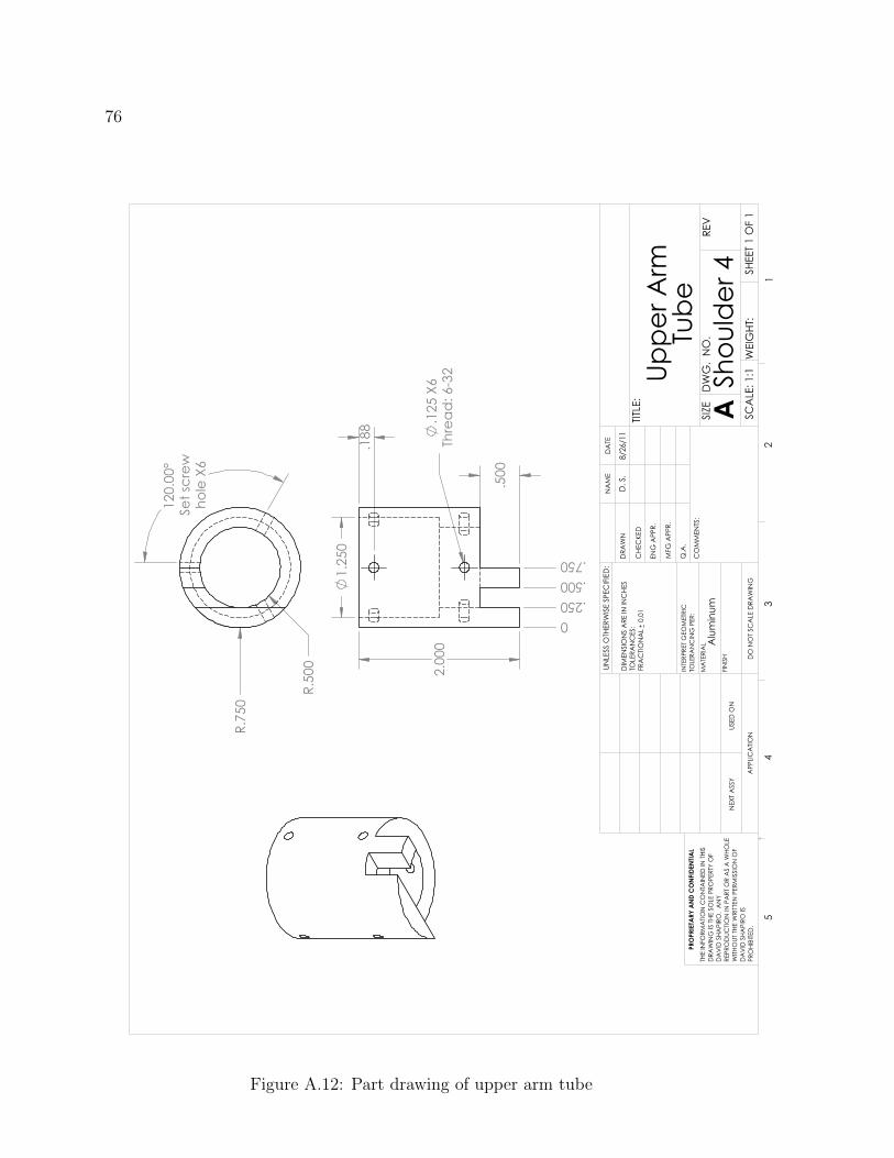
76
2.00
0.1
25 X
6Th
read
: 6-3
2
.500
.188
1.25
0
0.250.500.750
120.
00°
Set s
crew
hole
X6
R.75
0
R.50
0
Uppe
r Arm
Tube
DO
NO
T SC
ALE
DRA
WIN
G
Shou
lder
4 SHEE
T 1 O
F 1
8/26
/11
D. S
.
UNLE
SS O
THER
WIS
E SP
ECIF
IED
:
SCA
LE: 1
:1W
EIG
HT:
REV
DW
G.
NO
.
ASIZE
TITLE
:
NA
ME
DA
TE
CO
MM
ENTS
:
Q.A
.
MFG
APP
R.
ENG
APP
R.
CHE
CKE
D
DRA
WN
Alu
min
umFI
NIS
H
MA
TERI
AL
INTE
RPRE
T G
EOM
ETRI
CTO
LERA
NC
ING
PER
:
DIM
ENSI
ON
S A
RE IN
INC
HES
TOLE
RAN
CES
:FR
AC
TION
AL
0.0
1
APP
LICA
TION
USED
ON
NEX
T A
SSY
PRO
PRIE
TARY
AN
D C
ON
FIDE
NTIA
LTH
E IN
FORM
ATIO
N C
ON
TAIN
ED IN
THI
SD
RAW
ING
IS T
HE S
OLE
PRO
PERT
Y O
FD
AV
ID S
HAPI
RO.
AN
Y RE
PRO
DUC
TION
IN P
ART
OR
AS
A W
HOLE
WITH
OUT
THE
WRI
TTEN
PER
MIS
SIO
N O
FD
AV
ID S
HAPI
RO IS
PR
OHI
BITE
D.
54
32
1
Figure A.12: Part drawing of upper arm tube

77
A.4 The Elbow Assembly
Table A.4: BOM for elbow assembly
Item # Part # Description Qty.
4.1 2447K17 Easy-Adapt clevis rod end 2
4.2 - Elbow Linkage (Figure A.14, Page 73) 1

78
1
2
Elbo
w A
ssem
bly
DO
NO
T SC
ALE
DRA
WIN
G
Elbo
w 0
SHEE
T 1 O
F 1
8/26
/11
D. S
.
UNLE
SS O
THER
WIS
E SP
ECIF
IED
:
SCA
LE: 1
:2W
EIG
HT:
REV
DW
G.
NO
.
ASIZE
TITLE
:
NA
ME
DA
TE
CO
MM
ENTS
:
Q.A
.
MFG
APP
R.
ENG
APP
R.
CHE
CKE
D
DRA
WN
Alu
min
umFI
NIS
H
MA
TERI
AL
INTE
RPRE
T G
EOM
ETRI
CTO
LERA
NC
ING
PER
:
DIM
ENSI
ON
S A
RE IN
INC
HES
TOLE
RAN
CES
:FR
AC
TION
AL
0.0
1
APP
LICA
TION
USED
ON
NEX
T A
SSY
PRO
PRIE
TARY
AN
D C
ON
FIDE
NTIA
LTH
E IN
FORM
ATIO
N C
ON
TAIN
ED IN
THI
SD
RAW
ING
IS T
HE S
OLE
PRO
PERT
Y O
FD
AV
ID S
HAPI
RO.
AN
Y RE
PRO
DUC
TION
IN P
ART
OR
AS
A W
HOLE
WITH
OUT
THE
WRI
TTEN
PER
MIS
SIO
N O
FD
AV
ID S
HAPI
RO IS
PR
OHI
BITE
D.
54
32
1
Figure A.13: Elbow assembly
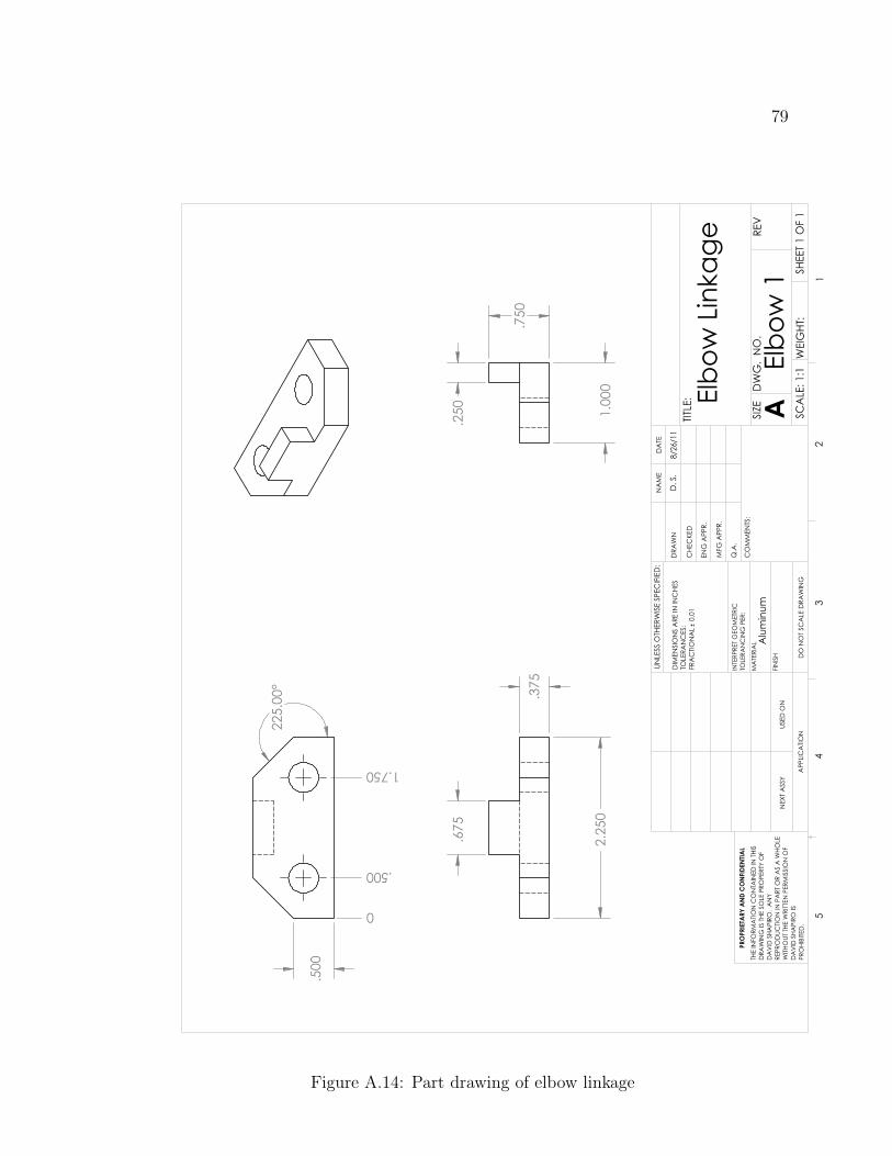
79
2.25
0
.375
.675
.750
1.00
0
.250
225.
00°
.500
0
.500
1.750
Elbo
w L
inka
ge
DO
NO
T SC
ALE
DRA
WIN
G
Elbo
w 1
SHEE
T 1 O
F 1
8/26
/11
D. S
.
UNLE
SS O
THER
WIS
E SP
ECIF
IED
:
SCA
LE: 1
:1W
EIG
HT:
REV
DW
G.
NO
.
ASIZE
TITLE
:
NA
ME
DA
TE
CO
MM
ENTS
:
Q.A
.
MFG
APP
R.
ENG
APP
R.
CHE
CKE
D
DRA
WN
Alu
min
umFI
NIS
H
MA
TERI
AL
INTE
RPRE
T G
EOM
ETRI
CTO
LERA
NC
ING
PER
:
DIM
ENSI
ON
S A
RE IN
INC
HES
TOLE
RAN
CES
:FR
AC
TION
AL
0.0
1
APP
LICA
TION
USED
ON
NEX
T A
SSY
PRO
PRIE
TARY
AN
D C
ON
FIDE
NTIA
LTH
E IN
FORM
ATIO
N C
ON
TAIN
ED IN
THI
SD
RAW
ING
IS T
HE S
OLE
PRO
PERT
Y O
FD
AV
ID S
HAPI
RO.
AN
Y RE
PRO
DUC
TION
IN P
ART
OR
AS
A W
HOLE
WITH
OUT
THE
WRI
TTEN
PER
MIS
SIO
N O
FD
AV
ID S
HAPI
RO IS
PR
OHI
BITE
D.
54
32
1
Figure A.14: Part drawing of elbow linkage
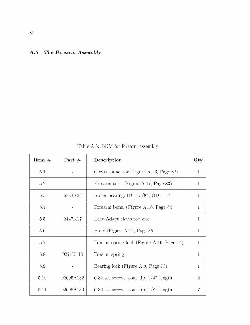
80
A.5 The Forearm Assembly
Table A.5: BOM for forearm assembly
Item # Part # Description Qty.
5.1 - Clevis connector (Figure A.16, Page 82) 1
5.2 - Forearm tube (Figure A.17, Page 83) 1
5.3 6383K23 Roller bearing, ID = 3/8”, OD = 1” 1
5.4 - Forearm bone, (Figure A.18, Page 84) 1
5.5 2447K17 Easy-Adapt clevis rod end 1
5.6 - Hand (Figure A.19, Page 85) 1
5.7 - Torsion spring lock (Figure A.10, Page 74) 1
5.8 9271K113 Torsion spring 1
5.9 - Bearing lock (Figure A.9, Page 73) 1
5.10 92695A132 6-32 set screws, cone tip, 1/4” length 2
5.11 92695A130 6-32 set screws, cone tip, 1/8” length 7

81
12
34
5
6
78
9
Flexio
n/Ex
tens
ion
Lock
DO
NO
T SC
ALE
DRA
WIN
GSH
EET 1
OF
1
8/26
/11
D. S
.
UNLE
SS O
THER
WIS
E SP
ECIF
IED
:
SCA
LE: 1
:10
WEI
GHT
:
REV
DW
G.
NO
.
ASIZE
TITLE
:
NA
ME
DA
TE
CO
MM
ENTS
:
Q.A
.
MFG
APP
R.
ENG
APP
R.
CHE
CKE
D
DRA
WN
Alu
min
umFI
NIS
H
MA
TERI
AL
INTE
RPRE
T G
EOM
ETRI
CTO
LERA
NC
ING
PER
:
DIM
ENSI
ON
S A
RE IN
INC
HES
TOLE
RAN
CES
:FR
AC
TION
AL
0.0
1
APP
LICA
TION
USED
ON
NEX
T A
SSY
PRO
PRIE
TARY
AN
D C
ON
FIDE
NTIA
LTH
E IN
FORM
ATIO
N C
ON
TAIN
ED IN
THI
SD
RAW
ING
IS T
HE S
OLE
PRO
PERT
Y O
FD
AV
ID S
HAPI
RO.
AN
Y RE
PRO
DUC
TION
IN P
ART
OR
AS
A W
HOLE
WITH
OUT
THE
WRI
TTEN
PER
MIS
SIO
N O
FD
AV
ID S
HAPI
RO IS
PR
OHI
BITE
D.
54
32
1
Figure A.15: Exploded view of forearm assembly
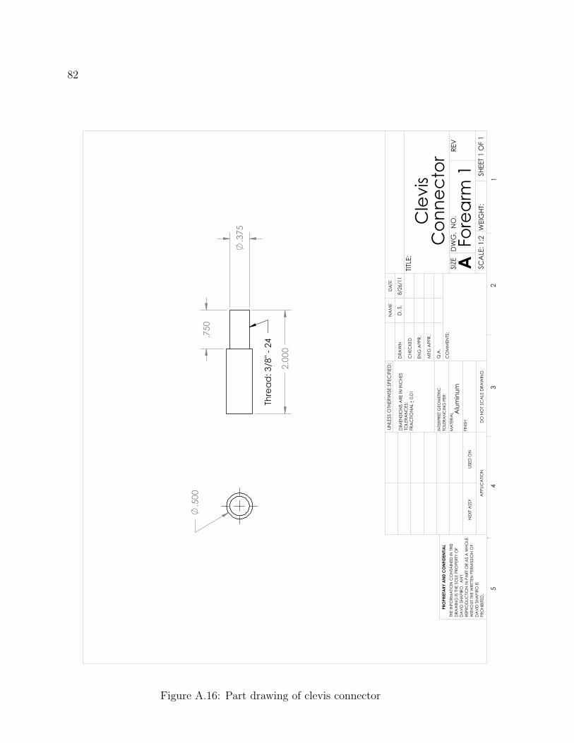
82
.500
.375
2.00
0
.750
Thre
ad: 3
/8" -
24
Cle
vis
Con
nect
or
DO
NO
T SC
ALE
DRA
WIN
G
Fore
arm
1 SHEE
T 1 O
F 1
8/26
/11
D. S
.
UNLE
SS O
THER
WIS
E SP
ECIF
IED
:
SCA
LE: 1
:2W
EIG
HT:
REV
DW
G.
NO
.
ASIZE
TITLE
:
NA
ME
DA
TE
CO
MM
ENTS
:
Q.A
.
MFG
APP
R.
ENG
APP
R.
CHE
CKE
D
DRA
WN
Alu
min
umFI
NIS
H
MA
TERI
AL
INTE
RPRE
T G
EOM
ETRI
CTO
LERA
NC
ING
PER
:
DIM
ENSI
ON
S A
RE IN
INC
HES
TOLE
RAN
CES
:FR
AC
TION
AL
0.0
1
APP
LICA
TION
USED
ON
NEX
T A
SSY
PRO
PRIE
TARY
AN
D C
ON
FIDE
NTIA
LTH
E IN
FORM
ATIO
N C
ON
TAIN
ED IN
THI
SD
RAW
ING
IS T
HE S
OLE
PRO
PERT
Y O
FD
AV
ID S
HAPI
RO.
AN
Y RE
PRO
DUC
TION
IN P
ART
OR
AS
A W
HOLE
WITH
OUT
THE
WRI
TTEN
PER
MIS
SIO
N O
FD
AV
ID S
HAPI
RO IS
PR
OHI
BITE
D.
54
32
1
Figure A.16: Part drawing of clevis connector

83
R.50
0
R.75
0
120.
00°
Set s
crew
ho
le X
3
3.20
0
.500
.750
1.25
0
150.
00°
1.00
0
.500
.125
X6
Thre
ad: 6
-32
0.250.500.750
Fore
arm
Tub
e
DO
NO
T SC
ALE
DRA
WIN
G
Fore
arm
2 SHEE
T 1 O
F 1
8/26
/11
D. S
.
UNLE
SS O
THER
WIS
E SP
ECIF
IED
:
SCA
LE: 2
:3W
EIG
HT:
REV
DW
G.
NO
.
ASIZE
TITLE
:
NA
ME
DA
TE
CO
MM
ENTS
:
Q.A
.
MFG
APP
R.
ENG
APP
R.
CHE
CKE
D
DRA
WN
Alu
min
umFI
NIS
H
MA
TERI
AL
INTE
RPRE
T G
EOM
ETRI
CTO
LERA
NC
ING
PER
:
DIM
ENSI
ON
S A
RE IN
INC
HES
TOLE
RAN
CES
:FR
AC
TION
AL
0.0
1
APP
LICA
TION
USED
ON
NEX
T A
SSY
PRO
PRIE
TARY
AN
D C
ON
FIDE
NTIA
LTH
E IN
FORM
ATIO
N C
ON
TAIN
ED IN
THI
SD
RAW
ING
IS T
HE S
OLE
PRO
PERT
Y O
FD
AV
ID S
HAPI
RO.
AN
Y RE
PRO
DUC
TION
IN P
ART
OR
AS
A W
HOLE
WITH
OUT
THE
WRI
TTEN
PER
MIS
SIO
N O
FD
AV
ID S
HAPI
RO IS
PR
OHI
BITE
D.
54
32
1
Figure A.17: Part drawing of forearm tube
84
.500
1.25
0
6.25
0
1.25
0
.375
Thre
ad: 3
/8" -
24
Fore
arm
Bon
e,Ra
dius
/Uln
a
DO
NO
T SC
ALE
DRA
WIN
G
Fore
arm
3 SHEE
T 1 O
F 1
8/26
/11
D. S
.
UNLE
SS O
THER
WIS
E SP
ECIF
IED
:
SCA
LE: 1
:2W
EIG
HT:
REV
DW
G.
NO
.
ASIZE
TITLE
:
NA
ME
DA
TE
CO
MM
ENTS
:
Q.A
.
MFG
APP
R.
ENG
APP
R.
CHE
CKE
D
DRA
WN
Alu
min
umFI
NIS
H
MA
TERI
AL
INTE
RPRE
T G
EOM
ETRI
CTO
LERA
NC
ING
PER
:
DIM
ENSI
ON
S A
RE IN
INC
HES
TOLE
RAN
CES
:FR
AC
TION
AL
0.0
1
APP
LICA
TION
USED
ON
NEX
T A
SSY
PRO
PRIE
TARY
AN
D C
ON
FIDE
NTIA
LTH
E IN
FORM
ATIO
N C
ON
TAIN
ED IN
THI
SD
RAW
ING
IS T
HE S
OLE
PRO
PERT
Y O
FD
AV
ID S
HAPI
RO.
AN
Y RE
PRO
DUC
TION
IN P
ART
OR
AS
A W
HOLE
WITH
OUT
THE
WRI
TTEN
PER
MIS
SIO
N O
FD
AV
ID S
HAPI
RO IS
PR
OHI
BITE
D.
54
32
1
Figure A.18: Part drawing of forearm bone
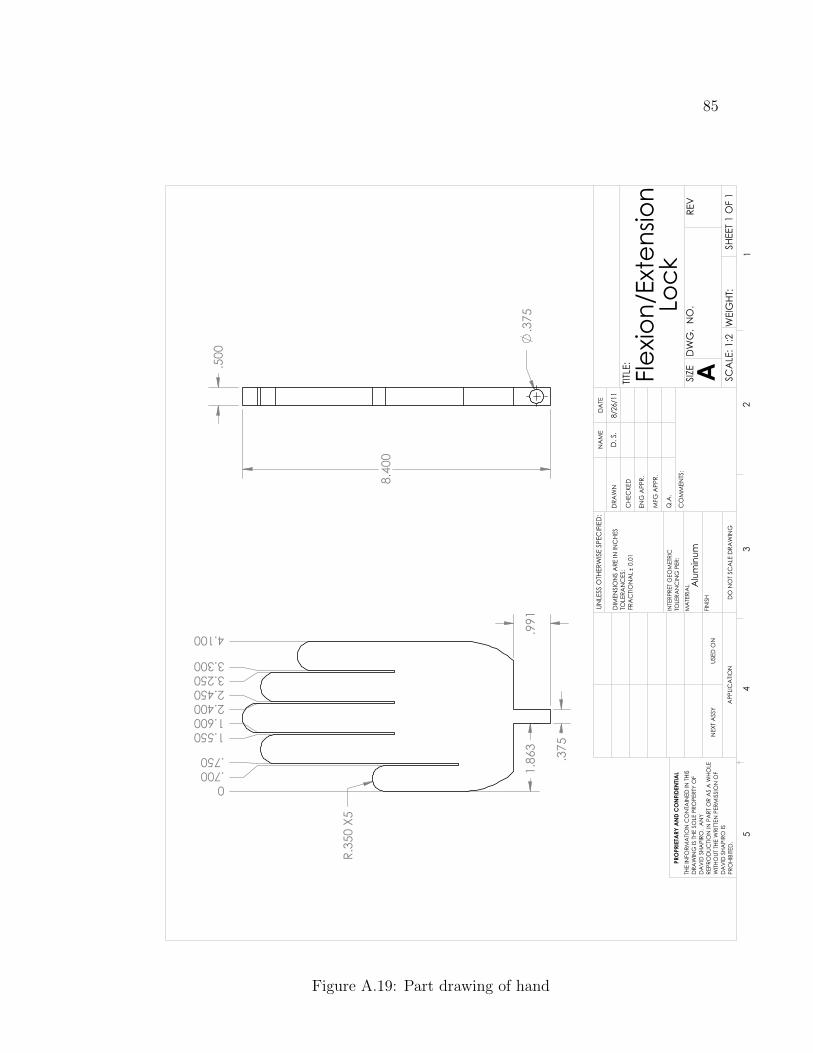
85
.375
R.35
0 X5
1.86
3.9
91
0.700.750
1.5501.6002.4002.4503.2503.300
4.100
8.40
0
.500
.375
Flexio
n/Ex
tens
ion
Lock
DO
NO
T SC
ALE
DRA
WIN
GSH
EET 1
OF
1
8/26
/11
D. S
.
UNLE
SS O
THER
WIS
E SP
ECIF
IED
:
SCA
LE: 1
:2W
EIG
HT:
REV
DW
G.
NO
.
ASIZE
TITLE
:
NA
ME
DA
TE
CO
MM
ENTS
:
Q.A
.
MFG
APP
R.
ENG
APP
R.
CHE
CKE
D
DRA
WN
Alu
min
umFI
NIS
H
MA
TERI
AL
INTE
RPRE
T G
EOM
ETRI
CTO
LERA
NC
ING
PER
:
DIM
ENSI
ON
S A
RE IN
INC
HES
TOLE
RAN
CES
:FR
AC
TION
AL
0.0
1
APP
LICA
TION
USED
ON
NEX
T A
SSY
PRO
PRIE
TARY
AN
D C
ON
FIDE
NTIA
LTH
E IN
FORM
ATIO
N C
ON
TAIN
ED IN
THI
SD
RAW
ING
IS T
HE S
OLE
PRO
PERT
Y O
FD
AV
ID S
HAPI
RO.
AN
Y RE
PRO
DUC
TION
IN P
ART
OR
AS
A W
HOLE
WITH
OUT
THE
WRI
TTEN
PER
MIS
SIO
N O
FD
AV
ID S
HAPI
RO IS
PR
OHI
BITE
D.
54
32
1
Figure A.19: Part drawing of hand
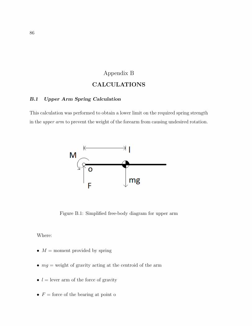
86
Appendix B
CALCULATIONS
B.1 Upper Arm Spring Calculation
This calculation was performed to obtain a lower limit on the required spring strength
in the upper arm to prevent the weight of the forearm from causing undesired rotation.
Figure B.1: Simplified free-body diagram for upper arm
Where:
• M = moment provided by spring
• mg = weight of gravity acting at the centroid of the arm
• l = lever arm of the force of gravity
• F = force of the bearing at point o
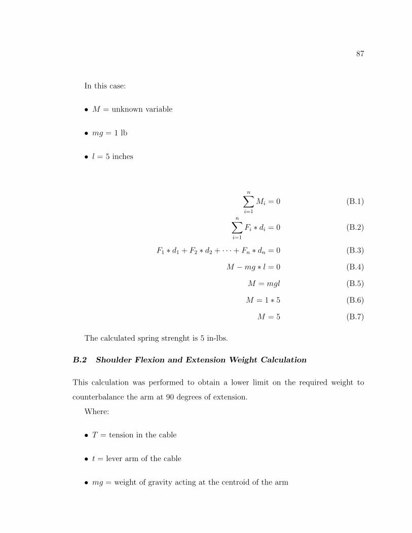
87
In this case:
• M = unknown variable
• mg = 1 lb
• l = 5 inches
n∑i=1
Mi = 0 (B.1)
n∑i=1
Fi ∗ di = 0 (B.2)
F1 ∗ d1 + F2 ∗ d2 + · · · + Fn ∗ dn = 0 (B.3)
M −mg ∗ l = 0 (B.4)
M = mgl (B.5)
M = 1 ∗ 5 (B.6)
M = 5 (B.7)
The calculated spring strenght is 5 in-lbs.
B.2 Shoulder Flexion and Extension Weight Calculation
This calculation was performed to obtain a lower limit on the required weight to
counterbalance the arm at 90 degrees of extension.
Where:
• T = tension in the cable
• t = lever arm of the cable
• mg = weight of gravity acting at the centroid of the arm

88
Figure B.2: Simplified free-body diagram of arm
• l = lever arm of the force of gravity
• F = force of the bearing at point a
• L = length of entire arm
• P = force acting at end of arm
In this case:
• T = unknown variable
• t = 1 inch
• mg = 2 lbs
• l = 14 inches
To calculate the force required to hold the arm level, T, we assume that P = 0
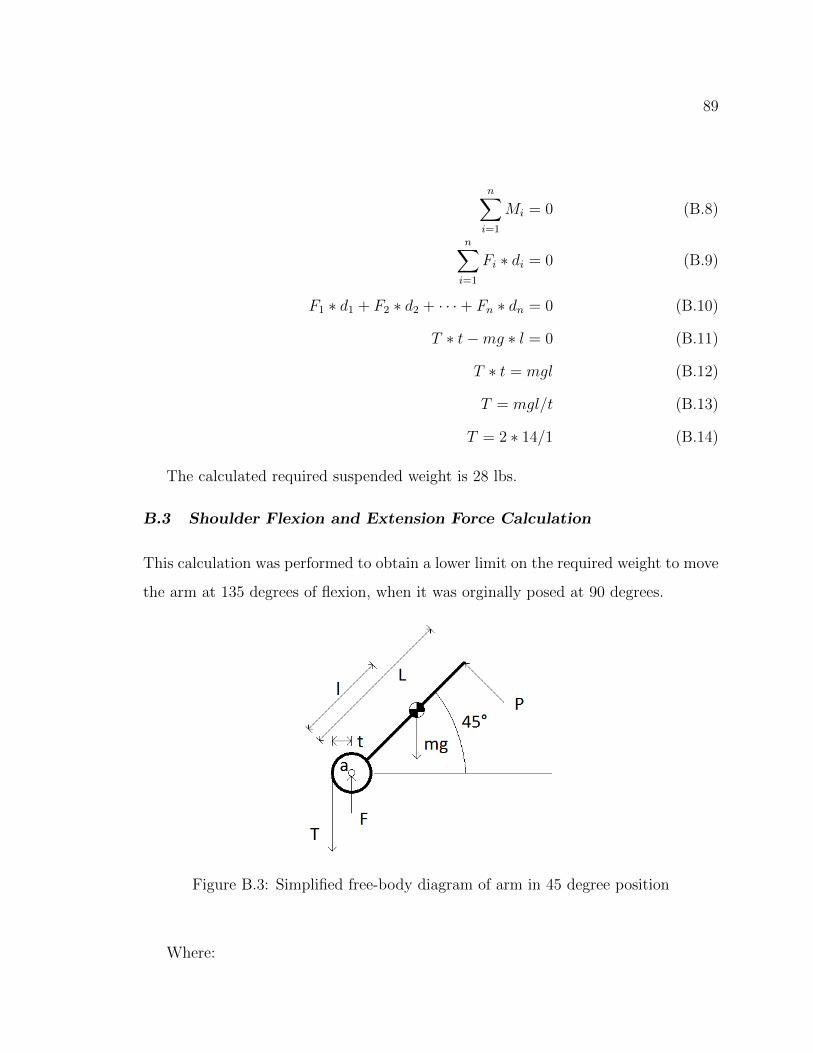
89
n∑i=1
Mi = 0 (B.8)
n∑i=1
Fi ∗ di = 0 (B.9)
F1 ∗ d1 + F2 ∗ d2 + · · · + Fn ∗ dn = 0 (B.10)
T ∗ t−mg ∗ l = 0 (B.11)
T ∗ t = mgl (B.12)
T = mgl/t (B.13)
T = 2 ∗ 14/1 (B.14)
The calculated required suspended weight is 28 lbs.
B.3 Shoulder Flexion and Extension Force Calculation
This calculation was performed to obtain a lower limit on the required weight to move
the arm at 135 degrees of flexion, when it was orginally posed at 90 degrees.
Figure B.3: Simplified free-body diagram of arm in 45 degree position
Where:

90
• T = tension in the cable
• t = lever arm of the cable
• mg = weight of gravity acting at the centroid of the arm
• l = lever arm of the force of gravity
• F = force of the bearing at point a
• L = length of entire arm
• P = force acting at end of arm
In this case:
• P = unknown variable
• T = 35 lbs
• t = 1 inch
• mg = 2 lbs
• l = 14 inches
• L = 20 inches
To calculate the torque required to move the arm from a level position to a 45
degree angle
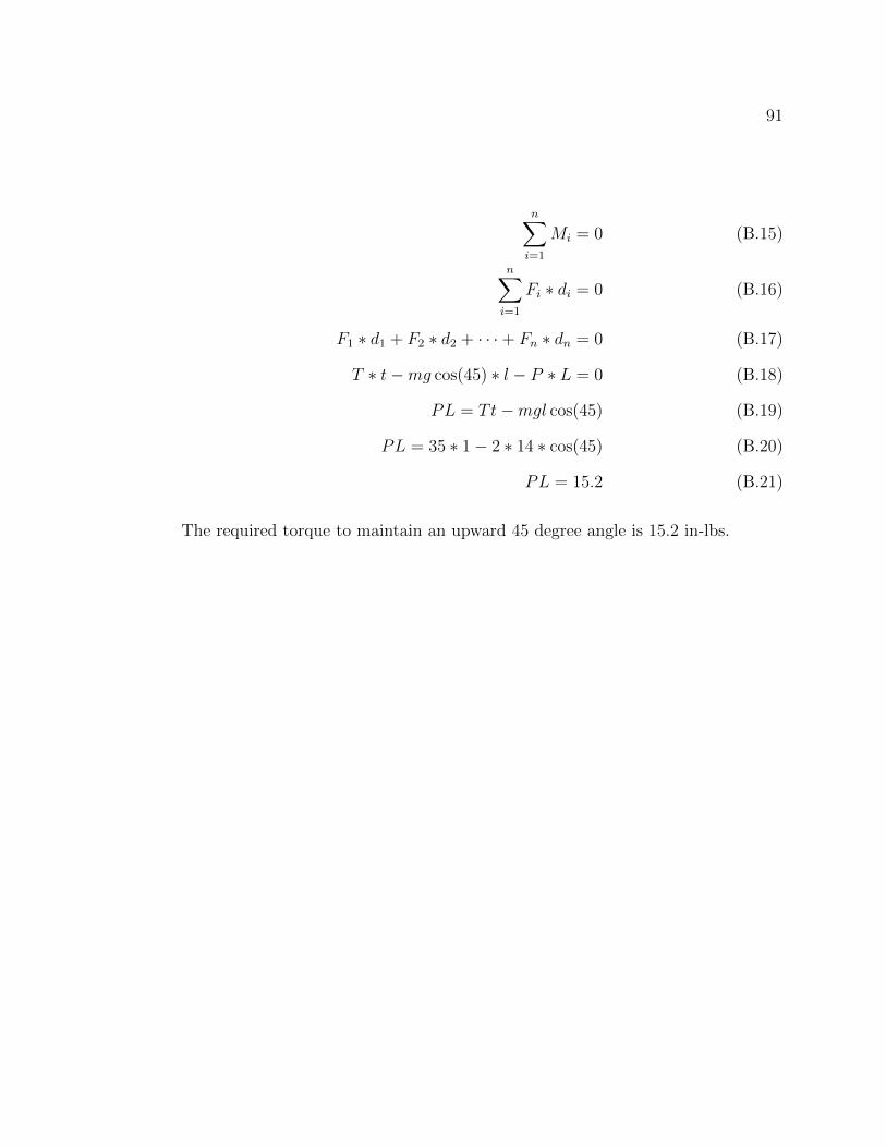
91
n∑i=1
Mi = 0 (B.15)
n∑i=1
Fi ∗ di = 0 (B.16)
F1 ∗ d1 + F2 ∗ d2 + · · · + Fn ∗ dn = 0 (B.17)
T ∗ t−mg cos(45) ∗ l − P ∗ L = 0 (B.18)
PL = Tt−mgl cos(45) (B.19)
PL = 35 ∗ 1 − 2 ∗ 14 ∗ cos(45) (B.20)
PL = 15.2 (B.21)
The required torque to maintain an upward 45 degree angle is 15.2 in-lbs.

92
Appendix C
DESIGN REQUIREMENTS
1. Overall Specifications
• Capable of being shipped while disassembled
e.g. UPS max weight of 150 lbs, up to 165” length and girth combined
• Capable of being transported by car when assembled
• Assembly to require no more than two people using hand or power tools
• Minimize assembly of full unit, no more than 5 actions
• Base to have wheels for ease of movement
• Base to have capability of being bolted to floor
• Base to be weighted for stability
• Overall dummy to match 50th percentile male (Figure C.1, Page 93)
• Joints and surfaces must be durable to withstand approximately 1 million
cycles
• Must be able to withstand strikes of up to 1500 lbs
• Joints and surfaces need to padded/protected to prevent injury
• Only head and hand need to exactly mimic human appearance
2. Hand
• Open hand position
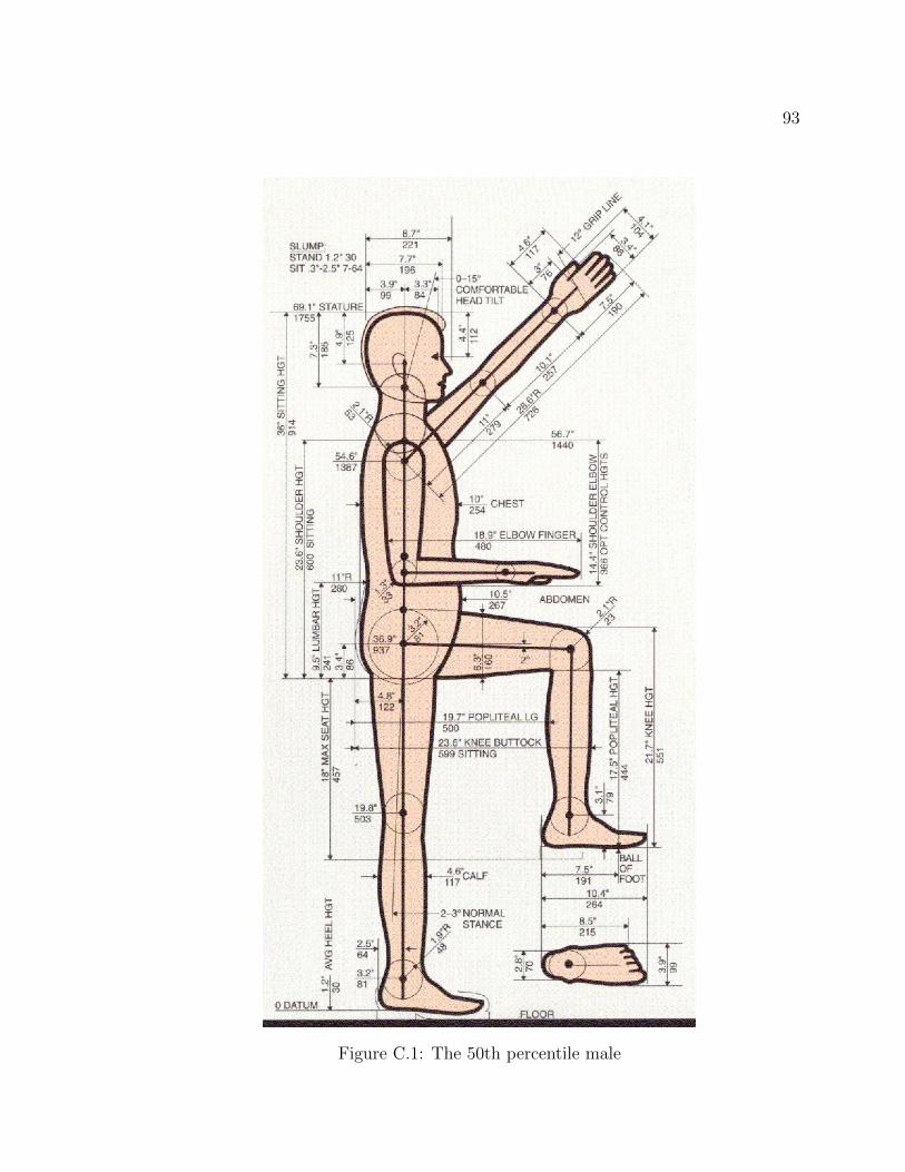
93
Figure C.1: The 50th percentile male

94
• Joints of hand do not need to move
However, a big plus if fingers are flexible enough to grab and manipu-
late
• Anatomically correct in size
• Sold palm
3. Wrist
• Neutral position: wrist stay flat, forearm to hand
• Limited movement: 80 degrees extension, 50 flexion
• Spring action to bring wrist back to neutral position
4. Forearm
• Neutral postion: vertial, thumb up
• Forearm rotation should take place in middle of forearm
• Limited movement: 90 degrees supination, 90 degree pronation
• Spring action to bring forearm back to neutral position
5. Elbow
• Neutral position: relaxed arm, approximately straight
• Limited motion: 15 degree extension, 90 degrees flexion
• Spring action to bring elbow back to neutral position
6. Upper Arm
• Neutral position: 20 degrees inward
• Limited motion: 60 degrees medial and lateral rotation
95
• Spring action to bring elbow back to neutral position
7. Arm Unit
• Each arm can be place in one of three positions
Low: with arm straight, hand should be at solar plexus level
Middle: with arm straight, hand should be at chin level
High: with arm straight, hand should be at forehead level
• User must be able to easily change from one position to another
• Low position
Elbow approximately 1 fist(4 in) from ribs
Wrist and elbow in vertical position
Inside of wrist in alignment with outside ofshoulder
8. Shoulder
• Neutral position: low, middle, or high
• Limited movement: flexion up to vertical, extension to 45 degrees behind
• Spring action to bring shoulder back to chosen neutral position
9. Head and neck
• Anthropomorphic head
• Spring in neck to allow movement
10. Torso and waist
• Spring in waist to allow movement
• Limited movement: 15 degees back, 90 degrees forward
• Pelvic bone represented for groin strikes