Embed Size (px)
Citation preview
Development of a behaviour-based controland software architecture for a visuallyguided mine detection robot
Daniela Doroftei*, ** — Eric Colon* — Yvan Baudoin* — HichemSahli**
* Royal Military Academy, Department of Mechanical Engineering (MSTA)Avenue de la Renaissance 30, B1000 Brussels, Belgium
{daniela.doroftei;eric.colon;yvan.baudoin}@rma.ac.be
** Vrije Universiteit Brussel, Department of Electronics and Informatics (ETRO)Pleinlaan 2, B1040 Brussels, Belgium
ABSTRACT. Humanitarian demining is a labor-intensive and high-risk which could benefit fromthe development of a humanitarian mine detection robot, capable of scanning a minefield semi-automatically. The design of such an outdoor autonomous robots requires the considerationand integration of multiple aspects: sensing, data fusion, path and motion planning and robotcontrol embedded in a control and software architecture. This paper focuses on three mainaspects of the design process: visual sensing using stereo and image motion analysis, design ofa behaviour-based control architecture and implementation of a modular software architecture.
RÉSUMÉ. : Le déminage humanitaire reste une opération laborieuse et risquée. Dans ce contexte,le but est de développer un robot mobile démineur capable de scanner un champ de mine demanière semi-automatique. La conception d’un tel robot doit prendre en considération différentsaspects: la perception et le fusion des données, l’ architecture de contrôle pour la navigationdu robot et son implémentation avec un logiciel adapté. Le système de perception utilisé dansce travail est basé sur la stereo vision et l’analyse du mouvement dans l’image. Le système decontrôle utilise une architecture modulaire basée sur les comportements.
KEYWORDS: Stereo vision, Image motion analysis, Behaviour-based robot control, Robot controland software architectures, Behaviour fusion, Robots for risky interventions.
MOTS-CLÉS : Stereo vision, Traitement de mouvement dans l’image, Contrôle basé sur les com-portements, Fusion de comportements, Robots pour interventions à risques.
296 JESA - 43/2009. Interactions homme-machine
1. Introduction
1.1. Goal and problem formulation
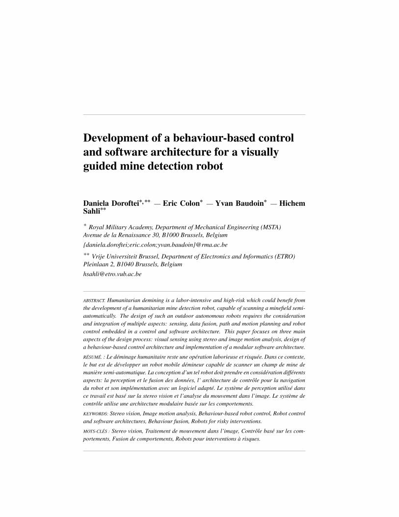
The goal of this research project is to prepare the ROBUDEM, an outdoor mobilerobot platform as shown on Figure 1 for a humanitarian demining application. In thissetup, the robot navigates and searches for mines by moving a metal detector, detectingsuspicious objects in the soil. Once a suspicious object is detected, the robot stops andinvokes its Cartesian scanning mechanism. This scanning mechanism performs a 2Dscan of the soil, allowing mine imaging tools to make a reliable classification of thesuspicious object as a mine or not. This paper describes partial aspects of this researchwork aimed at making the robot capable to scan a minefield semi-autonomously andreturn a map with locations of suspected mines.
During the design of all these sub-aspects, the outdoor nature of the robot has tobe taken into account, because outdoor robots face special difficulties compared totheir indoor counterparts. These include totally uncontrolled environments, changingillumination, thermal, wind and solar conditions, uneven and tough terrain, rain, etc.
Figure 1. ROBUDEM robot with the metal detector and a stereo camera

Towards mine detection robots 297
1.2. Previous work
For decades, autonomous robotics is a popular research area, yet the amount ofreal intelligent autonomous outdoor robots applied on the field is still very limited.The goal of the research project presented here is to develop intelligent autonomousrobotic agents which can assist humans for various types of risky outdoor interven-tions (surveillance, crisis management...). The challenges for such a robotic systemare tremendous and span various fields of research: from sensing and sensor fusion tomodeling and control, map building and path planning, decision making and auton-omy, and to the final integration of all these components. Three of these aspects areinvestigated more profoundly in this paper: visual sensing, robot control and the soft-ware architecture. The following paragraphs give an overview of the different existingalgorithms and design choices for these different components.
Robotic agents can rely on numerous types of sensors to gain knowledge aboutthe environment or about itself or its position. These sensors include infrared sensors,ultrasound sensors, laser range scanners, GPS, inertial navigation systems... Cogni-tive science and biological examples pointed out the importance of visual sensing,which led to the application of computer vision algorithms like stereo vision (Parket al., 2005), obstacle detection (DeSouza et al., 2002), person following (Enescuet al., 2005), visual servoing (Hong et al., 2001) to robotics and it eventually alsoled to mixed paradigms like visual simultaneous localisation and mapping (VSLAM)(Davison et al., 2007). However, integration of vision modules into a control archi-tecture for an autonomous mobile robot is more difficult than just adding the visioncomponents (Schlegel et al., 2000). This is due to the high bandwidth and processingrequirements of vision sensors, which require a task-specific configuration of vision-based behaviors. Another drawback of many computer vision algorithms is that theylack stability and robustness when confronted with varying illumination conditions, asit generally happens in outdoor situations, although illumination-invariant algorithmshave been proposed (DeCubber et al., 2004). For visual sensing, the Robudem robotis outfitted with a stereo camera system, consisting of two digital cameras. In orderto maximize the information stream towards the navigation unit, two different visualprocessing techniques are used: stereo vision and image motion analysis.
An autonomous mobile robot must be self-reliant to operate in complex, partiallyknown and challenging environments using its limited physical and computationalresources. Its control system must ensure in real time that the robot will achieveits tasks despite all these constraints (Medeiros, 1998). One of the first robot con-trol architectures was the Sense Model Plan Act (SMPA) paradigm. The primarydrawback of this approach is that the series of stages through which all sensor datamust pass places an unavoidable delay in the loop between sensing and action. Thisis a major problem with all deliberative approaches: since they rely on a worldmodel, they have difficulties with real-time performance in complex environments.To counter this drawback, alternatives, such as the behavior-based approach, wereproposed (Arkin, 1987),(Maes, 1989),(Mataric, 1997),(Brooks, 1986). Contrary todeliberative approaches, these behaviour-based control systems afford modular de-

298 JESA - 43/2009. Interactions homme-machine
velopment, real-time robust performance within a changing world and incrementalgrowth. In behavior-based control, the control of a robot is shared between a set ofpurposive perception-action units, called behaviors (Pirjanian, 1999). Based on se-lective sensory information, each behavior produces immediate reactions to controlthe robot with respect to a particular objective, a narrow aspect of the robot’s overalltask such as obstacle avoidance or wall following. Behaviors with different and pos-sibly incommensurable objectives may produce conflicting actions that are seeminglyirreconcilable. Thus a major issue in the design of behavior-based control systems isthe formulation of effective mechanisms for coordination of the behaviors’ activitiesinto strategies for rational and coherent behavior. This is known as the action selec-tion problem. Numerous action selection mechanisms have been proposed over thelast decade; a qualitative overview can be found in (Doroftei, 2006). The behavior-based controller presented here uses statistical reasoning on the output data of eachbehaviour to determine the stability and reliability and therefore also the activity levelof seven behaviours, each proposing a (different) velocity and turning prescript.
Robot control architectures become more and more complex, as human reasoningis mimicked. Moreover, there is a significant portion of robot functionality that iscommon to a large number of robotic systems in different application domains. Un-fortunately, most functionality implementations are tied to specific robot hardware,processing platforms and communication environments. Most research and develop-ment in software for robotic systems is based on proprietarily designed architecturesinvented from scratch. To avoid this, the choice of a flexible, extendable and real-time capable software architecture is crucial. This architecture has to ease the use ofreusable and transferable software components. Multiple software architectures, likeOrocos (Bruyninckx, 2001), Player/Stage (Gerkey et al., 2003), Campout (Pirjanianet al., 2000), CoRoBa (Colon et al., 2006), etc., have been proposed in the past, allwith their strengths and weaknesses. The existence of such a multitude of softwareframeworks hasn’t helped the standardisation of robot software architectures. In thecourse of this research project, the Modular Controller Architecture (MCA) (Schollet al., 2002) was employed. MCA is a modular, network transparent and realtimecapable framework targetted towards the control of autonomous robots.
This paper is structured as follows: in Section 2 the visual sensing is explained indetail. To maximize the information extracted from the visual camera data, two ap-proaches for visual obstacle detection are followed: classical stereo vision and imagemotion analysis. Section 3 describes the robot control architecture: first the generalarchitecture is explained, then the metal and mine detection groups are discussed. InSection 3.4, the behaviour-based navigation controller is presented, which ensuressemi-autonomous robot navigation, while Section 3.5 discusses how this navigationfits in the global framework of the robot motion scheduler. Section 4 describes theimplemented software architecture. First, the underlying MCA framework is intro-duced, then the implementation of the general control architecture is explained andafter that the implementation of the behaviour-based navigation controller in MCA isdiscussed. Finally, some results of experiments with the presented architecture on areal demining robot are presented and some conclusions are formulated.

Towards mine detection robots 299
2. Visual sensing
2.1. Stereo vision
Stereo vision employs the difference in location between two cameras. This dif-ference in space leads to two images where the same points can be found at differentpositions. The goal of stereo disparity estimation is finding the correct correspon-dences between image points from the left and right camera. For this, we use thealgorithm presented in (Birchfield, 1997). The algorithm matches individual pixelsin corresponding scanline pairs while allowing occluded pixels to remain unmatched,then propagates the information between scanlines. The algorithm handles large un-textured regions, uses a measure of pixel dissimilarity that is insensitive to image sam-pling, and prunes bad search nodes to increase the speed of dynamic programming.The output of this algorithm is a dense depth map of the area in front of the cameras,as shown in Figure 2. On the depth map in Figure 2c, nearby objects appear dark.The cross on top marks the location of the closest obstacle, which is the darkest pointon the depth map and which corresponds here to the obstacle in front of the robot.The data-content of this dense depth map must now be reduced to be useful for thenavigation controller. For this, we use the approach proposed by Schafer in (Schaferet al., 2005). Following this method, the dense depth map is downprojected onto theground surface, such that it can be represented as a 2D line as shown in Figure 2d.This data is further reduced in dimensionality by calculating from the depth line thedistance to the nearest obstacle on the left dl, in the middle dc, and on the right dr.
(a) (b)
(c) (d)
Figure 2. a) left camera image; b) right camera image; c) dense depth map (white =far, dark = near); d) depth line with nearest distances to obstacles on the left, in themiddle and on the right

300 JESA - 43/2009. Interactions homme-machine
2.2. Image motion analysis
Motion analysis can provide extra information about the environment. The ratio-nale behind the usage of the image motion for navigation purposes is that when largeimage motion is detected, this is likely due to objects close to the camera (and thusclose to the robot), which requires an appropriate reaction from the obstacle avoidancemodule. On the other hand, when few image motion is detected, this means that theway in front of the camera is probably quite clear of obstacles.
Multiple techniques stand at our disposal to estimate the image motion. Thesemethods differ in their approach according to the main problem to be solved in imagemotion: the background estimation and subtraction process. As the camera system isinstalled on a moving robot system, background estimation is particularly difficult inthis case, as it is very hard to build up a model of the background over a large amountof time. This constraint limits the use of traditional advanced background estima-tion techniques like kernel density estimators, mean shift or mixtures of Gaussians(Piccardi, 2004). As a result, the frame difference between successive frames wasemployed to find back the moving objects. As expressed by Equation [1], the motionmk for each pixel is robustly estimated by calculating the frame difference when thedifference is above a certain threshold which is dependent on the robot velocity V .
mk ={
0|framei − framei−1|
if |framei − framei−1| < cVif |framei − framei−1| > cV
[1]
With c a constant describing the relation between robot speed and image motion. OnFigure 3, this image motion field is shown as calculated by the right robot camera.
To come to one single numerical value m representing the amount of motion ina camera image, the resulting motion field is summed over the whole image domain,
giving m =all pixels∑
k=1
mk. This calculation is performed once for the left camera and
once for the right camera image, leading to two distinct image motion estimates.
(a) (b) (c)
Figure 3. Image motion field of right camera: a) image at ti−1; b) image at ti; c)image motion field

Towards mine detection robots 301
3. Robot control architecture
The control architecture describes the strategy to combine the three main capabil-ities of an intelligent mobile agent: sensing, reasoning and actuation. These three ca-pabilities have to be integrated in a coherent framework in order for the mobile agentto perform a certain task adequately. A number of control strategies can be set up,varying from simple serial sense-model-plan-act strategies to complex hybrid meth-ods. As the robot task involves achieving goals which are not defined at designtime,a purely reactive strategy will not suffice in our case, unless it is extremely (and thusprohibitively) complex. A robot which is required to navigate to various locationsspecified by the user at runtime cannot perform this task reactively unless its state-action policy includes states for each of the possible goal locations. Purely reactiveapproaches achieve great efficiency because of their minimal computation. However,since they have so little representational power, they lack runtime flexibility. To com-bine the advantages of purely reactive and planner-based approaches, this researchwork aims at implementing a hybrid control strategy which fuses a behaviour-basedcontroller for autonomous navigation with automation aspects for mine scanning. Abehaviour-based robot control architecture was chosen because of the flexible andmodular nature of behaviour-based controllers, facilitating the design process. Ad-ditionally, a common property of behaviorbased systems is their distributed nature;they consist of a collection of parallel, concurrently executing behaviors devoid of acentralized arbiter or reasoner. The performance of the behaviour-based controller de-pends on the implementation of the individual behaviours as well as on the methodchosen to solve the behaviour fusion or action selection problem.
3.1. General architecture
The working principle of the proposed control architecture is sketched on Figure4. There are three distinctive modules: Navigation (on the right side on Figure 4),Mine Detection - Scanning (in the middle on Figure 4) and Metal Detection (on theleft side on Figure 4). These three processes are controlled by a watchdog, the robotmotion scheduler, which manages the execution of each module and decides on thecommands to be sent to the robot actuators. This robot motion scheduler is explainedmore in detail in Section 3.5. In normal situations (when no suspicious objects aredetected), the leftmost and rightmost modules (Metal Detection and Navigation) areboth active. In this situation, the metal detector senses continuously for metal in thesoil and the navigation module steers the robot towards a certain goal, while avoidingobstacles. When metal is found, the central module, Mine Detection, is activated bythe robot motion scheduler. In this case, the robot is stopped as the navigation moduleis no longer active and the cartesian scanner searches for metal in a predefined pattern.The output of this scanning procedure is used by mine imaging tools to determinewhether the suspected metal object is a mine or not. This information is used by thenavigation procedure as extra sensor input, as mines need to be avoided too.

302 JESA - 43/2009. Interactions homme-machine
In the following sections, the different groups depicted in Figure 4 are presentedmore in detail.
Figure 4. The general robot control architecture
3.2. Metal detection
The metal detector scans for metal in the soil. If no metal is found, it keeps ondoing this and the robot keeps on moving. If a metal is found, this is reported to therobot motion scheduler, which takes the appropriative actions. We will not elaboratehere on the implementation of a metal detecting sensor, as it is out of the scope of thispaper.
3.3. Mine detection
The Cartesian scanning mechanism makes a 2D scan with the metal detector.Combining all the individual metal detector measurements, on obtains an image ofthe soil. An example of such an image is given in Figure 5. In this image, the brightoval areas on Figure 5 have a mine-like shape and size, so they need to be treated assuspected objects. Such an analysis is performed automatically by mine imaging tools,which determine the likelihood of mine occurrence and the exact position of eventualmines. It is obvious that the diverse nature of modern mines can make this processvery difficult. The Royal Military Academy, leading the Belgian HUDEM project, hasbeen focussing for several years on the development of new data processing and fu-

Towards mine detection robots 303
sion algorithms for mine detection (Milisavljevic, 1999), on the improvement of minedetecting sensors and on robotic systems that carry these sensors. This paper focusseson the third research topic, so we will not discuss these mine detection algorithms anyfurther.
Figure 5. Example result of an image of the soil obtained by making a cartesian scanwith a metal detector
If a mine is found, this is reported to the robot motion scheduler, which takesthe appropriative actions. In addition to this the Mine detector acts as a sensor formines, as it returns the locations of mines, which need to be considered as obstaclesthemselves.
3.4. Behaviour-based navigation controller
For the Robudem robot, three main sensing capabilities are installed: odometry,stereo vision and image motion analysis. These three sensing capabilities are pro-cessed by separate behaviours. In this context, the odometry information is used forguiding the robot to a given goal position, while the visual sensors are used for obsta-cle avoidance.The main advantage of using behaviour-based approaches is that eachof the different behaviours can be designed and implemented separately. The generalscheme of the behaviour-based navigation module is shown on Figure 6. As indicatedby Figure 6, the behaviour-based controller has a hierarchical structure. At the lowestlevel, we can find the sensor input data for the behaviour-based controller consisting ofodometry information and stereo images. From the visual input stream, two abstract

304 JESA - 43/2009. Interactions homme-machine
sensors are deduced as explained in Section 2: stereo vision and image motion anal-ysis. This leads to three main behaviours defined for robot navigation: goal seeking,avoiding obstacles using stereo vision data and avoiding obstacles using image mo-tion analysis. As the architecture is modular, more behaviours can be added efficiently.Behaviour fusion then extracts consistent control commands from these individual be-haviours. The output of this behaviour-based navigation planner are velocity (V ) andturn angle (TFront, TRear) commands. The reason for having two different turn anglecommands is related to the mechanical structure of the Robudem robot, which has atwo-by-two differential drive system, meaning front and back wheels can be given adifferent turning angle, allowing for highly flexible maneuvering on difficult terrain.This also allows for different drive modes to be adopted by the robot. It is our finalaim to let the behavioural controller decide which is the best drive mode given theterrain circumstances. For now, the user can select on the graphical user interface thedesired drive mode and TFront and TRear are calculated accordingly.
Figure 6. General scheme of the behaviour-based navigation module
We will now explain the different components of the behaviour-based controllerdepicted in Figure 6 more in detail in a bottom up approach, so starting with explain-ing the different individual behaviours. Each of these behaviours calculates its ownvelocity and turn angle for the robot. These velocity and turn prescripts are calculatedat behaviour level as follows:

Towards mine detection robots 305
– the avoid obstacles using stereo vision behaviour receives as data dl and dr, thedistances to obstacles on the left and right side of the robot, by stereo vision analysis.The smaller the distance to obstacles, the more carefully and slowly the robot mustmove. The velocity VS is therefore directly proportional to the mean of the measureddistances left and right as expressed by Equation [2]:
VS = cSdl + dr
2[2]
with cS a normalization constant. When the distance to obstacles on the left side islarger than the distance to obstacles on the right side, the robot should avoid theseobstacles on the right by turning to the left. This relation between robot turn angle anddistances to obstacles is expressed by Equation [3]:
TS = cS (dl − dr) [3]as such, the distance to obstacles is maximized;
– the avoid obstacles using image motion behaviour receives as data ml and mr,the movement in the left and the right camera measured by the image motion analysis.The more movement in the image, the more probable there are objects close to therobot, so the velocity should be lowered. The robot speed VM is as such inverselyproportional to the image motion as expressed by Equation [4]:
VM = 1− cMml + mr
2[4]
with cM a normalization constant. When the movement on the left side is larger thanthe movement on the right side, the robot should avoid these probable obstacles on theleft by turning to the right, meaning the robot turn angle can be calculated from themovement in the images as given by Equation [5]:
TM = 1− cM (ml −mr) [5]
– the goal seeking behaviour receives as data the estimate of the robot position(xR, yR) and orientation θR as calculated by the odometry and robot kinematics. Theestimation of the robot motion and posture is done via a non-linear method namedthe dynamic extension algorithm, as presented in (Habumuremyi et al., 2005). Therobot position is compared with the desired goal position (xG, yG) and orientation θG
and a velocity VP and turn angle TP command are calculated from this information.The velocity of the robot should be maximal if the robot is far enough from the goaland should be reduced when approaching the goal. Therefore, the calculation of thevelocity command is split in two parts:
VP ={
vmax if dtarget > dthresholddtarget
dthresholdvmax if dtarget < dthreshold
[6]
with dtarget the distance to the goal, calculated from the robot and goal position anddthreshold a certain security distance above which the robot is allowed to drive withthe maximum robot velocity vmax. The turn angle command can be calculated byexpressing that the heading of the robot and the target should be the same:
TP = −(
θR − θG
cP
)3
[7]

306 JESA - 43/2009. Interactions homme-machine
with cP a normalization constant.
Behaviour fusion deals with distilling a coherent robot command from the indi-vidual behaviour prescripts. Therefore, the outputs of the behaviours are weighedaccording to the activity level A of the specific behaviour as expressed by Equations[8] and [9]. The activity level of a behaviour describes to which degree this behaviouris relevant for the calculation of the final robot command.
V = (1−AE)(
ASVS + AMVM + AP VP
AS + AM + AP
)[8]
T = AF,R
(ASTS + AMTM + AP TP
AS + AM + AP
)[9]
with:
– V and T respectively the velocity and turning command for the robot;– AE the activity level for the Emergency Stop which allows the user to de-activate
the robot at all time-instances via the user interface for security reasons;– AF , AR the activity levels for Front Steering and Rear Steering, which decide
on the drive mode which will be adopted by the robot;– AS , AM , AP the activity levels for, respectively, the Obstacle Avoidance using
Stereo Vision, Obstacle Avoidance using Image Motion Analysis and Goal Seekingbehaviour;
– VS , VM , VP the Velocity commands from, respectively, the Obstacle Avoidanceusing Stereo Vision, Obstacle Avoidance using Image Motion Analysis and Goal Seek-ing behaviour;
– TS , TM and TP the turn angle commands coming from, respectively, the Obsta-cle Avoidance using Stereo Vision, Obstacle Avoidance using Image Motion Analysisand Goal Seeking behaviour.
A major issue in the design of behaviour-based control systems is the formulationof effective mechanisms for coordination of the behaviours’ activities into strategiesfor rational and coherent behavior. Such fusion mechanisms are based upon the calcu-lation of the activity levels as presented above. These activity levels should reflect therelevance of the specific behaviour. The principle behind the calculation of the activitylevels is that the output of a behaviour should be stable over time in order to trust it.Therefore, the degree of relevance or activity is calculated by observing the historyof the output - a velocity and turn angle - of each behaviour. This history-analysisis performed by comparing the current output to a running average of previous out-

Towards mine detection robots 307
puts, which is transformed to a normalized standard deviation. For the stereo visionbehaviour, these standard deviations are expressed by Equations [10] and [11]:
σS,V = cV
i∑
k=i−h
VS,k −
N∑j=1
VS,j
N
2
[10]
σS,T = cT
i∑
k=i−h
TS,k −
N∑j=1
TS,j
N
2
[11]
with cV and cT two normalization constants.
The larger this standard deviation, the more unstable the output values of the be-haviour are, so the less they can be trusted. The same approach is followed for theimage motion (subscript M ) and the goal seeking (subscript P ) behaviours. Thisleads to an estimate for the activity levels as expressed by Equation [12]:
AS/M/P =(1− σS/M/P,V
)+
(1− σS/M/P,T
)[12]
For stability reasons, the activity level is initialized at a certain value (in general 0.5)and this estimate is then iteratively improved. The presented approach towards cal-culating the activity levels has some major advantages over traditional methods. Incomparison to classic fuzzy logic data fusion approaches where the number of rulesgrows in general rapidly with the number of inputs, the complexity only increases lin-early in this approach. Moreover, it is very modular, easily updateable and the resultcan be calculated very quickly. One of the disadvantages of this method is that the nor-malization constants ci must be user-determined. However, this process of parametertuning only needs to be performed once for each abstract sensor, as the normalizationconstants ci are independent of one another.
As such, all information necessary to calculate Equations [8] and [9] is known,meaning that the behaviour-based navigation controller can propose a robot controlcommand in the form of a velocity and turning command. This data is given as aninput to the robot motion scheduler which will execute it, unless another module hasa higher priority task (and trajectory) to perform.

308 JESA - 43/2009. Interactions homme-machine
3.5. The robot motion scheduler
The robot motion scheduler needs to decide which of the modules is executed andwhich of them can influence the robot actuators through robot commands. Its flowdiagram is sketched on Figure 7.
There are two main paths through the robot scheduler, one for the (normal) situa-tion of exploring while avoiding obstacles and detecting metals and one for the situa-tion where metal is found and more thorough investigation is needed (mine detection)while the robot is standing still.
In a normal situation, occurring e.g. in an initial situation (default inputs), the metaldetector is activated but the scanner is turned off. The navigation module returns at alltime instances a robot action prescript, as this module loops infinitely without interac-tion with the other modules. This trajectory is set as the trajectory to be executed, butwith a low priority.
If the metal found trigger is given, the metal detector is switched off. The trajec-tory for the robot is set to a predefined movement, more specifically, to back off alittle. This is done to be able to centre the scanning metal detection better around thesuspicious object. This trajectory has a high priority. When this movement is com-pleted, the robot is halted, by giving a "no movement" trajectory with a high priority.Finally, the scanning metal detection module is activated.
Figure 7. The control architecture for the robot motion scheduler

Towards mine detection robots 309
4. A modular software architecture
4.1. An introduction to MCA
As control architectures which aim to mimic human thinking tend to rapidly be-come highly complex, the use of a flexible, extendable and real-time capable softwarearchitecture is very important. Such a software architecture has to ease the develop-ment and reuse of software components. The chosen software architecture, MCA(Modular Controller Architecture) as presented by Scholl in (Scholl et al., 2002),achieves this by employing simple modules with standardized interfaces. The com-munication in MCA is managed via transporting edges that connect modules together.The main programs only consist of constructing modules that are connected via edgesand pooled into a group. This results in an equal programming on all system lev-els. As modules can be integrated both on Windows, Linux and on RT-Linux withoutchanges, they can be developed on Linux-side and then transferred later to RT-Linux.As errors in RT-Linux lead to system-hangs this development strategy prevents frommany reboot cycles and results in faster software development.
Each MCA module has a structure as shown on Figure 8 and is determined byfour connectors with the outside world: Sensor input (left below), Sensor output (lefttop), Control Input (right top), Control Output (right below). As a result sensor datastreams up, control commands stream down. The Sensor input and output are con-nected through a Sense procedure which enables to process the sensor data and theControl input and output are connected through a Control procedure which enablesto process the control commands. On Figure 8, sensor data flow is shown in yellow,control command flow in red.
Figure 8. An MCA module made up of a Sensor Input and Sensor Output edge, linkedby a Sense procedure and a Control Input and Control Output edge, linked by a Con-trol procedure
This modular structure is particularly convenient for behaviour-based architecturesas the individual behaviours translate easily to corresponding MCA-modules. This iswhy we chose MCA above other software architectures.

310 JESA - 43/2009. Interactions homme-machine
4.2. The general control architecture
The general robot control architecture, as presented in Section 3.1, is translatedinto an MCA scheme as shown on Figure 9. The architecture features a layered hi-erarchical structure with three levels. The first level consists of low level sensor pro-cessing modules such as the stereo framegrabber and the metal detector, together withlow-level actuator controlling modules such as the uplink to the Robudem robot andto the cartesian scanner. One level higher in the hierarchy, high-level abstract sensorssuch as the stereo vision module, the image motion analysis module and the mineimaging module process the data received by the low-level sensors. These image pro-cessing steps were explained more in detail in Section 2. Also the robot kinematicsand dynamics module which provides the odometry data can be found at this level. Itcan be observed that when changing the robot platform, only the robot kinematics anddynamics module and the robot uplink need to be rewritten. This allows for fast andeasy development of control architectures for multiple robotic platforms, based upona common codebase. Eventually, the high-level abstract sensors output their data tothe navigation controller, which decides on the robot actions, in conjunction with therobot motion scheduler, as explained in Section 3.1. The structure of this navigationcontroller in MCA is explained in Section 4.3.
Figure 9. General MCA scheme for the robot controller
Towards mine detection robots 311
4.3. The general behaviour-based navigation controller
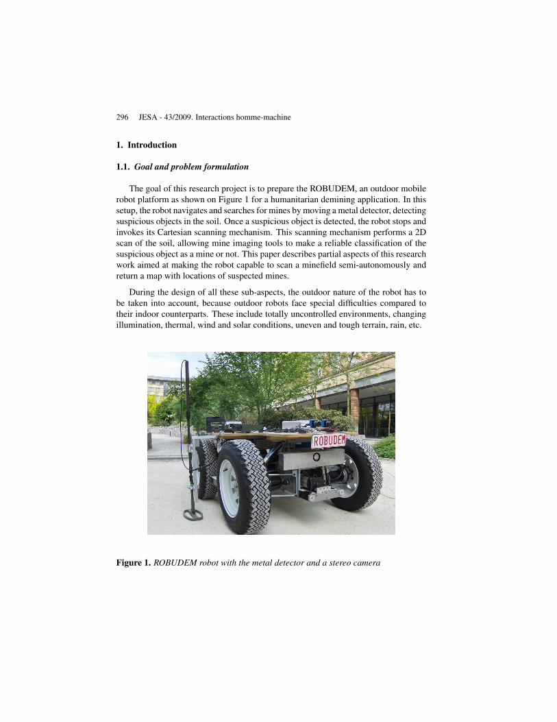
The MCA scheme for the behaviour-based controller is shown on Figure 10. Itconsists of the three main behaviours explained before, controlled (fused) by a Be-haviourSelector module.
Figure 10. MCA scheme for the behaviour-based controller
The sensory input received by the behaviour-based controller and represented onthe bottom left of Figure 10, consists of the distances to obstacles: dl, dc, dr fromthe stereo vision module; the motion in the left and right camera ml, mr from theimage motion analysis module and the robot position (xR, yR) and orientation θR
as estimated by the odometry. This data is processed by the stereo vision, imagemotion and goal seeking behaviours, outputting a velocity and turning prescript. TheBehaviourSelector module receives as input the output of the different behaviours andcalculates the activity levels for each of these behaviours according to Equations [12].
All of the three main behaviours also send the calculated velocity setup value to theVelocity module, where the data fusion occurs, based on the activity levels which werecalculated by the BehaviourSelector module. The EmergencyStop behaviour, whichcan be triggered by the user or when an obstacle is detected within a security distance,ensures that the velocity command is only transferred to the robot in safe conditions.
For the turning behaviour, a similar approach is followed; only in this case thereare two separate fusion behaviours the navigation behaviours can send their resultsto. As explained before, this is the case because the robot can assume different drivemodes. For example, for car-like driving, only the front wheels are steered and for
312 JESA - 43/2009. Interactions homme-machine
crab-like driving, all wheels turn in the same direction. It is the BehaviourSelectorwhich decides on the drive mode based on user input and sets the activity levels forfront and rear steering accordingly.
5. Results
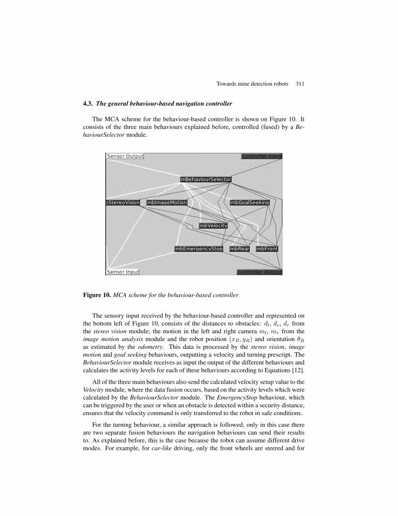
The result of the presented research project is a generic robot control architecturewhich can be used for the control of different real and simulated robots. Of course,when switching robots, some modules need to be interchanged, such as for examplethe RobuDem Uplink module, which is responsible for translating MCA commands torobot commands and back. The global achievements of this research project can bediscussed by taking a look at the Graphical User Interface (GUI) in Figure 11, as itshows the important features of the Robudem controller.
Figure 11. User Interface of the Robudem navigation controller
On the upper left, the stereo camera images are visible, which are rectified tofacilitate the calculation of the depth map. The dense depth map is then postprocessed,as is shown on the images on the lower left. In the top middle of the interface, themeasurements of the abstract visual sensors stereo vision and image motion analysisare shown using colored bars. These indicate for the stereo vision sensor the distancesto obstacles on the left, middle and centre and for the image motion sensor the motionin the left and right camera image.

Towards mine detection robots 313
At the right of the interface, the activity levels of the different behaviours areshown. As can be noticed, the BehaviourSelector has found here that the Image-Motion behaviour delivers more reliable results than the StereoVision behaviour. Thisis in this case due to the lack of texture in the camera images, which renders the densedepth map estimation less robust. On the lower right of this robot control interfacethe map of suspected mine locations is shown, as detected by the robot metal/minedetector. Red dots indicate suspected mine areas.
6. Conclusions
In this paper, we presented three main aspects of the design process of an intelli-gent autonomous robotic agent for demining interventions: visual sensing, behaviour-based control and the software architecture. Multiple visual cues, stereo vision andimage motion analysis, were integrated into the robot control and software architec-ture. A behaviour based control architecture was proposed, using statistical reasoningto solve the action selection problem. All components were implemented using amodular software architecture to achieve a future-proof design. The integration ofthese aspects enables the robot to search for mines in a designated area while avoidingobstacles.
The purely reactive nature of the presented framework is certainly the major draw-back of the approach. Therefore, it is the aim of future research to combine the pre-sented behavior-based approach with model based reasoning. For this, we are de-veloping a visual simultaneous localization and mapping (V-SLAM) system, whichcan automatically map the environment and place the robot in this map. Moreover,a differential GPS system and an orientation sensor will be placed on the robot. Byintegrating the information from these sensors with visual data in a SLAM context,the precision of the robot localisation will be further increased.
7. References
Arkin R., “ Motor Schema based navigation for a mobile robot: An approach to programmingby behavior”, IEEE International Conference on Robotics and Automation, p. 264-271,1987.
Birchfield S., Klt: An implementation of the kanade-lucas-tomasi feature tracker, Technicalreport, http://www.ces.clemson.edu/stb/klt/, Jan. , 1997.
Brooks R., “ A robust layered control system for a mobile robot”, IEEE Journal of Roboticsand Automation, vol. 2, n˚ 1, p. 14-23, 1986.
Bruyninckx H., “ Open robot control software: the OROCOS project”, Proc. Int. Conf. onRobotics and Automation, vol. 3, p. 2523-2528, 2001.
Colon E., Sahli H., Baudoin Y., “ CoRoBa, a multi mobile robot control and simu-lation frame-work”, International Journal of Advanced Robotic Systems, vol. 3, n˚ 1, p. 73-78, 2006.
Davison A., Reid I., “ MonoSLAM: Real-Time Single Camera SLAM”, IEEE Trans. on Patternanalysis and machine intelligence, vol. 29, n˚ 6, p. to appear, 2007.

314 JESA - 43/2009. Interactions homme-machine
DeCubber G., Berrabah S., Sahli H., “ Color-Based Visual Servoing Under Varying IlluminationConditions”, Robotics and Autonomous Systems, vol. 47, n˚ 3, p. 225-249, 2004.
DeSouza G., Kak A., “ Vision for Mobile Robot Navigation: A Survey”, IEEE Transactions onPattern Analysis and Machine Intelligence, vol. 24, n˚ 2, p. 237-267, 2002.
Doroftei D., Behavior based Robot Navigation Techniques - State of the Art, Technical reportand lecture notes, Royal Military Academy of Belgium, Oct. , 2006.
Enescu V., DeCubber G., Cauwerts K., Berrabah S., Sahli H., Nuttin M., “ Active Stereo Vision-based Mobile Robot Navigation for Person Tracking”, Proc. Int. Conf. on Informatics inControl, Automation and Robotics, vol. 2, p. 32-39, 2005.
Gerkey B., Vaughan R., Howard A., “ The Player/Stage Project: Tools for Multi-Robot andDistributed Sensor Systems”, Proc. Int. Conf. on Advanced Robotics, Portugal, 2003.
Habumuremyi J., Houpin J., “ Model of a wheeled robot named Robudem and design of astate feedback controller for its posture tracking: simulation and experiment”, ISMCR05,Brussels, Belgium, November, 2005.
Hong P., Sahli H., Colon E., Baudoin Y., “ Visual Servoing for Robot Navigation”, Proc. 3rdInt. Conf. on Climbing and Walking Robots, Germany, p. 255-264, 2001.
Maes P., How To Do The Right Thing, Technical report ne 43-836, AI-Laboratory, Mas-sachusetts Institute of Technology, 1989.
Mataric M., “ Behavior-based control: Examples from navigation, learning and group be-haviour”, Journal of Experimental en Theoretical Artificial Intelligence, special issue onSoftware Architectures for Physical Agents, vol. 9, n˚ 2-3, p. 323-336, 1997.
Medeiros A., “ A survey of control architectures for autonomous mobile robots”, Journal of theBrazilian Computer Society, 1998.
Milisavljevic N., “ Mine shape detection and data fusion considerations”, Proc. of the HUDEMWorkshop, Brussels, Belgium, 1999.
Park C., Kim S., Paik J., “ Stereo vision-based autonomous mobile robot”, Intelligent Robotsand Computer Vision XXIII: Algorithms, Techniques, and Active Vision, vol. 6006, p. 256-264, 2005.
Piccardi M., “ Background subtraction techniques: a review”, Proc. IEEE Int. Conf. on Systems,Man and Cybernetics, vol. 4, p. 3099-3104, 2004.
Pirjanian P., Behavior coordination mechanisms - state-of-the-art, Technical report and LectureNotes n˚ Tech. Report IRIS-99-375, Institute of Robotics and Intelligent Systems, Univer-sity of Southern California, Oct. , 1999.
Pirjanian P., Huntsberger T., Trebi-Ollennu A., Aghazarian H., Das H., Joshi S., Schenker P.,“ CAMPOUT: a control architecture for multirobot planetary outposts”, Proc. SPIE Conf.Sensor Fusion and Decentralized Control in Robotic Systems, USA, 2000.
Schafer H., Proetzsch M., Berns K., “ Stereo-Vision-Based Obstacle Avoidance in Rough Out-door Terrain”, International Symposium on Motor Control and Robotics, 2005.
Schlegel C., Illmann J., Jaberg H., Schuster H., Worz R., “ Integrating vision-based behaviorswith an autonomous robot”, Videre, 2000.
Scholl K., Gassmann B., Albiez J., Zollner. J., “ MCA - Modular Controller Architecture”,Robotik 2002, 2002.
ANNEXE POUR LE SERVICE FABRICATIONA FOURNIR PAR LES AUTEURS AVEC UN EXEMPLAIRE PAPIERDE LEUR ARTICLE ET LE COPYRIGHT SIGNE PAR COURRIER
LE FICHIER PDF CORRESPONDANT SERA ENVOYE PAR E-MAIL
1. ARTICLE POUR LA REVUE :
JESA - 43/2009. Interactions homme-machine
2. AUTEURS :
Daniela Doroftei*, ** — Eric Colon* — Yvan Baudoin* — HichemSahli**
3. TITRE DE L’ARTICLE :
Development of a behaviour-based control and software architecture fora visually guided mine detection robot
4. TITRE ABRÉGÉ POUR LE HAUT DE PAGE MOINS DE 40 SIGNES :
Towards mine detection robots
5. DATE DE CETTE VERSION :
February 23, 2009
6. COORDONNÉES DES AUTEURS :
– adresse postale :* Royal Military Academy, Department of Mechanical Engineering(MSTA)Avenue de la Renaissance 30, B1000 Brussels, Belgium{daniela.doroftei;eric.colon;yvan.baudoin}@rma.ac.be
** Vrije Universiteit Brussel, Department of Electronics and Informatics(ETRO)Pleinlaan 2, B1040 Brussels, [email protected]
– téléphone : 00 322 742 65 54– télécopie : 00 322 742 65 47– e-mail : -
7. LOGICIEL UTILISÉ POUR LA PRÉPARATION DE CET ARTICLE :
LATEX, avec le fichier de style article-hermes.cls,version 1.23 du 17/11/2005.
8. FORMULAIRE DE COPYRIGHT :
Retourner le formulaire de copyright signé par les auteurs, téléchargé sur :http://www.revuesonline.com
SERVICE ÉDITORIAL – HERMES-LAVOISIER14 rue de Provigny, F-94236 Cachan cedex
Tél. : 01-47-40-67-67E-mail : [email protected]
Serveur web : http://www.revuesonline.com