Embed Size (px)
Citation preview
www.rcmt.cvut.cz
CZECH TECHNICAL UNIVERSITY IN PRAGUE | FACULTY OF MECHANICAL ENGINEERING
Department of Production Machines and Equipment | PME
Research Center of Manufacturing Technology | RCMT
Petr Kolar, Matej Sulitka, Jaroslav Šindler
Development methods for
high performance machine tools
8.5.2014

2
Presentation overview
1. challenges in the design of large machine tools
2. point of success in machine tool design
3. description of the development methodology
4. case study 1: kinematics of a milling machine
5. case study 2: cross beam optimization of a portal milling machine
6. conclusions

3
Challenging requests of machine tool user
● competition in the segment of large machine tools (working space > 1 m3) has
increased over the last years
● customers are asking for:
– lower price machine tool total cost reduction through the cost reduction of all
all components (mainly structural parts = structural mass reduction)
– shorter delivery times modular design
– higher productivity and efficiency multifunctionality (milling, drilling, turning,
grinding…)
– higher accuracy better static and dynamic stiffness, thermal stability

4
Challenging requests of machining technologies
● typical 3+2 operation (with indexed rotary axes)
– typical operation: face milling, pocketing, drilling
– new cutting strategies: circular milling, plunging
● increasing volume of high performance structural
materials
– high alloyed steels, Ti alloys, Ni alloys
– composites (CFK, GFK)
● all these factors increase requests for:
– higher movement speeds
– higher spindle power
– higher accuracy
Courtesy: Walter

5
Relations between machine tool user and producer
machine tool user machine tool producer
workpiece
size, material,
technological operations
surface quality,
accuracy, productivity
stiffness, accuracy,
performance
machine tool price,
running costsprice of the workpiece
acceptable market price point of success of the
whole production chain
cutting tool and
machine tool

6
Complexity of development of a new machine tool
technology requirements
(power, speed, force)
other customer requirements
(max. feed, energy
consump.)
price limit of the machine
workpiece spectrum
inputs:
variables:
machine structure and size
structural material
concept/proposal of drives
modular structural parts
proposal of linear
and rotary joints
machine tool development process
machine tool concept
machine tool design
modern optimization methods
can support the decision-making
process within the beginning
development phase of a new
machine tool, where there is a
low level of information on the
machine tool

7
Integrated development approach
Task
definitionTopology
optimization
Parametric
optimizationFinal design
check
Design input data:
machine kinematics, axis strokes, max. dimensions, material information
Functional demands:
static stiffness, modal properties, dynamic stiffness, feed drive pass bands
First design
proposal
Conceptual
topology
optimization

8
Case study 1: The machine tool optimal kinematics
● case study: decision making in case of the machine tool optimal kinematics
● task requirements:
– five axis milling machine tool with a table diameter of 1,600 mm
– solution for low mass and high stiffness
● two different kinematic structures:
– type A: a bridge-type machine with a vertical movable ram and movable table
– type B: a one-column-type machine with a horizontal ram and movable table
Type A Type B
9
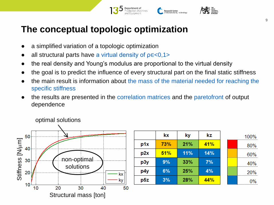
● a simplified variation of a topologic optimization
● all structural parts have a virtual density of ρ∈<0,1>
● the real density and Young’s modulus are proportional to the virtual density
● the goal is to predict the influence of every structural part on the final static stiffness
● the main result is information about the mass of the material needed for reaching the
specific stiffness
● the results are presented in the correlation matrices and the paretofront of output
dependence
The conceptual topologic optimization
Structural mass [ton]
Stiffness [N
/mm
]
non-optimal
solutions
optimal solutions

10
Boundary conditions
● fixation of the columns to the ground
● input forces in x, y, z directions in tool center point

11
● five geometrical parameters were defined for dimensional variation of the structure
● one parameter of virtual density and Young’s modulus
Parametric FE model
Increased column
width in the X
direction – p1x
D = <0, 1500> mm
Increased cross
beam width in the X
direction – p2x
D = <0, 1000> mm
Increased column
width in the Y
direction – p3y
D = <0, 1500> mm
Increased cross
beam width in the Y
direction – p4y
D = <0, 1000> mm
Increased cross
beam width in the
Z direction – p5z
D = <0, 500> mm

12
Structural mass [ton] Structural mass [ton]
Stiffne
ss [N
/mm
]
Stiffne
ss [N
/mm
]
Results for variant A
● the paretofront consists of all optimal variants
● effective mass range <8 t, 20 t> for maximizing of
stiffness in the X and Y direction
● effective mass range <8 t, 30 t> for maximizing of
stiffness in the Z direction
● increasing of total structural mass over 25 tons
does not increase the static stiffness significantly X
YZ
13
Structural mass [ton] Structural mass [ton]
Stiffne
ss [N
/mm
]
Stiffne
ss [N
/mm
]
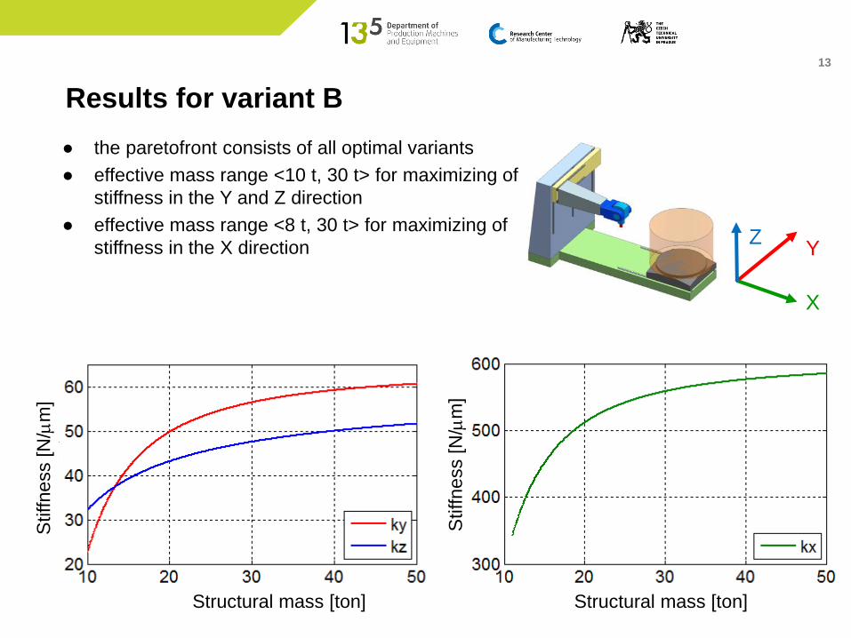
Results for variant B
● the paretofront consists of all optimal variants
● effective mass range <10 t, 30 t> for maximizing of
stiffness in the Y and Z direction
● effective mass range <8 t, 30 t> for maximizing of
stiffness in the X direction
X
YZ

14
Summary: comparison of variants
● comparison of machines with total
weight of 15 tons: type B has higher
stiffness and lower movement mass
● the conceptual topology
optimization can support the key
decision about the machine concept
before the development process of
the machine tool starts
X
YZ
15
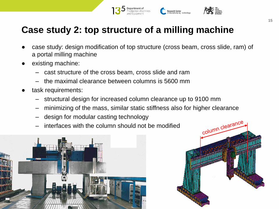
Case study 2: top structure of a milling machine
● case study: design modification of top structure (cross beam, cross slide, ram) of
a portal milling machine
● existing machine:
– cast structure of the cross beam, cross slide and ram
– the maximal clearance between columns is 5600 mm
● task requirements:
– structural design for increased column clearance up to 9100 mm
– minimizing of the mass, similar static stiffness also for higher clearance
– design for modular casting technology
– interfaces with the column should not be modified

16
● design space defined by the cross section of an existing cross beam
● loading with own weight and with forces in X and Y direction
● observed results: movement in the X and Y direction, rotation in the Y direction
Design space and boundary conditions
DxDy
rotY
deformation
due to own weight
Fy
static deformation in X
direction
Dx
Fx
17
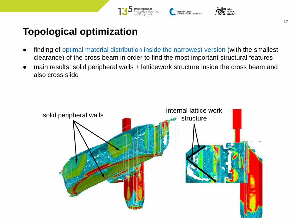
Topological optimization
● finding of optimal material distribution inside the narrowest version (with the smallest
clearance) of the cross beam in order to find the most important structural features
● main results: solid peripheral walls + latticework structure inside the cross beam and
also cross slide
solid peripheral wallsinternal lattice work
structure

18
various optimal results
X d
efo
rmation [
um
]
mass [kg]
Parametric model of the design proposal
● parametric optimization computes properties of various parametric models
● the result is a paretofront of the optimal dimensional shape (including wall and rib
thicknesses) of the model variant (cross beam, cross slide and ram)
● parametric optimization of the narrowest version in order to find the optimal
structure dimensions

19
Modular design & thickness optimization
● modular design using the modular
casting technology (mould model
consists of specific segments)
● a new parametric model has been
prepared with respect to additional
segments for the cross beam
prolongation
● the length and the structure of the
model changes with the addition of
specific segments
+0,5 m
basic version
+1,5 m
+1 m
+2,5 m
+2 m
20
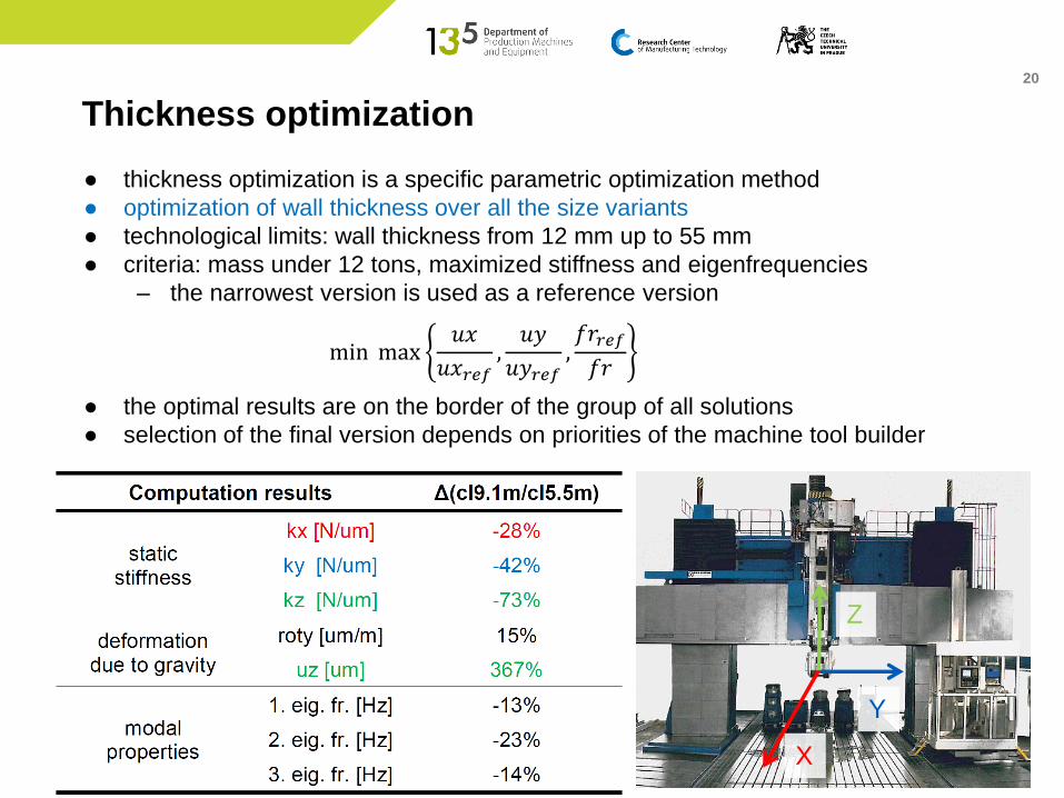
Thickness optimization
● thickness optimization is a specific parametric optimization method
● optimization of wall thickness over all the size variants
● technological limits: wall thickness from 12 mm up to 55 mm
● criteria: mass under 12 tons, maximized stiffness and eigenfrequencies
– the narrowest version is used as a reference version
● the optimal results are on the border of the group of all solutions
● selection of the final version depends on priorities of the machine tool builder
min max 𝑢𝑥
𝑢𝑥𝑟𝑒𝑓,𝑢𝑦
𝑢𝑦𝑟𝑒𝑓, 𝑓𝑟𝑟𝑒𝑓
𝑓𝑟
Y
X
Z

21
Summary and conclusion of the case study
● a combination of topologic and parametric optimization is a strong tool for finding
of the optimal machine tool design with minimized structural material volume
● the method is applicable for modular design of parts for a combined optimization
through structural parts shape and a through the size variants
● mass reduction potential on typical machine tool structures is 10-40%

22
Conclusions
● the machine tool development process is a complex task
– many inputs and requirements should be taken into account and evaluated in
relation with each other
● modern optimization methods can support decision making during the whole machine
tool development process
● an integral approach should be used – a proper combination of topologic and
parametric optimization shows big potential for structural mass reduction
● design & optimization chain can be configured for every specific task
● application of the mentioned methodology shows big potential for the design of new
high performance machine tools with respect to the technological and market
challenges
23
Dr. Petr Kolar
collaborative projects
Dr. Matej Sulitka
head of simulation group
Jaroslav Šindler
advanced FEM specialist
Thank you for your attention
www.rcmt.cvut.cz