Embed Size (px)
Citation preview
1
Safety in Mines Research Advisory Committee
Draft Final Project Report
Draft Final Project Report
DEVELOPMENT, EVALUATION AND TESTING
OF AN ALTERNATIVE ONBOARD CONTINUOUS MINER SCRUBBERS AND FORCE FAN IN-
HEADING VENTILATION SYSTEM FOR CONTINUOUS MINER HEADINGS IN SOUTH
AFRICAN COALMINES
RW Ottermann NDL Burger AJ von Wielligh
Research Agency BE@UP, University of Pretoria Project number SIM 050401 Date of report February 2012
2
EXECUTIVE SUMMARY
An alternative to onboard continuous miner scrubbers and force in-heading fan ventilation system was developed. The system was successfully evaluated and demonstrated to industry. Increased effectiveness of in-heading ventilation with lower flammable gas and airborne dust concentrations was demonstrated and the noise levels were slightly lower. Making use of this system in coalmines would have the following impact:
o Reduced risk of airborne particles and thereby reducing pneumoconiosis.
o Reduced risk of coal dust explosions caused by airborne particles. o Reduced risk of methane explosions.
After a literature survey, measurement of underground conditions and consultations with industry and equipment manufacturers, the project was defined and a project scope was agreed on. Concepts were generated and the designs were done making use of Computational Fluid Dynamic (CFD) modelling. The design, building and testing of the prototype scrubbers was an iterative process, including an Experimental Development Model (XDM), prototype, modified prototype and prototype to be fitted on Continuous Miner. After evaluations, a new design was done and a new prototype built before being retested. The system developed consists of the following sub-systems:
o Ventilation system (take positive control of airflow): The fan of the scrubber is connected to ducting which channels the air out of the boxcut and a jet fan positioned at the entrance of the boxcut forces fresh air into the boxcut.
o A new scrubber making use of a rotating cloth, which is continuously cleaned by a water spray system.
o Use of surfactants.
3
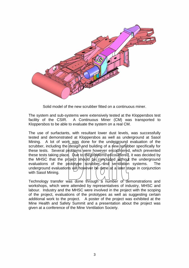
Solid model of the new scrubber fitted on a continuous miner.
The system and sub-systems were extensively tested at the Kloppersbos test facility of the CSIR. A Continuous Miner (CM) was transported to Kloppersbos to be able to evaluate the system on a real CM.
The use of surfactants, with resultant lower dust levels, was successfully tested and demonstrated at Kloppersbos as well as underground at Sasol Mining. A lot of work was done for the underground evaluation of the scrubber, including the design and building of a new scrubber specifically for these tests. Several problems were however encountered, which prevented these tests taking place. Due to the problems encountered, it was decided by the MHSC that the project should be concluded without the underground evaluations of the prototype scrubber and ventilation systems. The underground evaluations will however be done at a later stage in conjunction with Sasol Mining. Technology transfer was done through a number of demonstrations and workshops, which were attended by representatives of industry, MHSC and labour. Industry and the MHSC were involved in the project with the scoping of the project, evaluations of the prototypes as well as suggesting certain additional work to the project. A poster of the project was exhibited at the Mine Health and Safety Summit and a presentation about the project was given at a conference of the Mine Ventilation Society.

4
ACKNOWLEDGEMENTS
The authors would like to express their gratitude to the Safety in Mines Research Advisory Committee (SIMRAC) for financial support of project SIM 050401 and also for the interest and technical input of the SIMRAC Technical Committee. The authors would also like to thank Sasol Mining and Joy Mining Machinery for their support and cooperation in the project.
5
TABLE OF CONTENTS Page
1 INTRODUCTION ....................................................................................... 4
2 METHODOLOGY ...................................................................................... 5
3 SCOPE OF PROJECT AND SYSTEM SPECIFICATION: ........................ 8
3.1 PROJECT SCOPE .................................................................................. 8
3.2 SYSTEM SPECIFICATION ........................................................................ 8
4 MEASURING OF OPERATIONAL PARAMETERS ................................ 10
4.1 DETERMINATION OF AIRFLOW PATTERNS IN BOXCUT: ............................. 11
4.2 UNDERGROUND DUST MEASUREMENTS ................................................ 14
5 CONCEPT STUDY .................................................................................. 15
5.1 CONCEPT DESIGN .............................................................................. 15
5.2 PREFERRED CONCEPT ........................................................................ 15
5.3 COMPUTATIONAL FLUID DYNAMIC (CFD) EVALUATIONS OF ALTERNATIVES
16
6 DESIGN OF PROTOTYPE ...................................................................... 19
6.1 EXPERIMENTAL DEVELOPMENT MODEL (XDM) SCRUBBER ...................... 19
6.2 PROTOTYPE SCRUBBER ...................................................................... 20
6.3 DESIGN MODIFICATIONS ...................................................................... 23
6.4 PROTOTYPE TO BE FITTED ON CONTINUOUS MINER FOR UNDERGROUND
EVALUATIONS ................................................................................................ 23
7 BUILD PROTOTYPE ............................................................................... 25
7.1 BUILD EXPERIMENTAL DEVELOPMENT MODEL (XDM) SCRUBBER ............ 25
7.2 BUILD PROTOTYPE SCRUBBER ............................................................. 26
7.3 MODIFIED PROTOTYPE SCRUBBER ....................................................... 28
7.4 PROTOTYPE TO BE FITTED ON CONTINUOUS MINER FOR UNDERGROUND
EVALUATIONS ................................................................................................ 28
8 SURFACE TESTING ............................................................................... 30
8.1 TEST OF EXPERIMENTAL DEVELOPMENT MODEL (XDM): ........................ 30
8.2 DUST MEASUREMENTS ....................................................................... 31
8.3 COMPARATIVE VENTILATION AND METHANE DILUTION TESTS OF PROTOTYPE
SCRUBBER .................................................................................................... 33
8.4 COMPREHENSIVE VENTILATION AND METHANE DILUTION TESTING OF
MODIFIED PROTOTYPE SCRUBBER WITH CM ..................................................... 38 8.4.1 Test ........................................................................................................... 38
8.4.2 Tests procedure ........................................................................................ 44
8.4.3 Test results ............................................................................................... 46
8.4.4 Conclusions .............................................................................................. 53
9 INVETSIGATIONS INTO OPRATIONAL ASPECTS AND ALTERNATIVE SCRUBBER PLACEMENT ..................................................................... 54
9.1 NEGATING FIRST CUT WITH NEW SCRUBBER CONCEPT ........................... 54
6
9.2 BALANCE BETWEEN THE JET FAN AND EXHAUST FAN (SCRUBBER FAN) ..... 57
9.3 POSITIONING OF THE SCRUBBER IN THE LAST THROUGH-ROAD ............... 57
10 UNDERGROUND EVALUATIONS .......................................................... 59
10.1 SURFACTANTS ................................................................................... 59
10.1 PROTOTYPE SCRUBBER AND VENTILATION SYSTEM ................................ 61
11 TECHNOLOGY TRANSFER ................................................................... 62
11.1 DEMONSTRATIONS AND WORKSHOPS ................................................... 62 11.1.1 Workshop and demonstration: 7 April 2006 ........................................ 62
A WORKSHOP AND DEMONSTRATIONS WERE HELD AT THE KLOPPERSBOS TEST
FACILITY OF THE CSIR. INTERESTED PARTIES FROM THE ................................... 62 11.1.2 Workshop and demonstration: 5 October 2006 ................................... 62
11.1.3 Demonstration to industry: 8 March 2007 .......................................... 62
11.1.4 Workshop and demonstration: 18 April 2007 ...................................... 62
11.1.5 WORKSHOP AND DEMONSTRATION: 3 FEBRUARY 2009 ...................... 63
11.2 EXHIBITION AT MINE HEALTH AND SAFETY SUMMIT ............................... 63
11.3 PRESENTATION AT MINE VENTILATION SOCIETY .................................... 64
12 CONCLUSIONS ...................................................................................... 65
13 REFERENCES ........................................................................................ 66
APPENDIX A: ................................................................................................ 67
PROJECT SCOPE AND APPROPRIATE METHODOLOGY FOR THE DEVELOPMENT, EVALUATION AND TESTING OF AN ALTERNATIVE TO ONBOARD CONTINUOUS MINER SCRUBBERS AND FORCE FAN IN-HEADING VENTILATION SYSTEMS FOR CONTINUOUS MINER HEADINGS IN SOUTH AFRICAN COALMINES .................................... 67
APPENDIX B: ................................................................................................ 73
COMPUTATIONAL FLUID DYNAMIC (CFD) EVALUATIONS OF ALTERNATIVE VENTILATION SYSTEMS ............................................. 73
APPENDIX C: ................................................................................................ 74
MANUFACTURING DRAWINGS OF PROTOTYPE SCRUBBER ................ 74
1
LIST OF FIGURES Page
Figure 3-1: General information regarding CM miners ..................................... 9
Figure 4-1: Grid for measuring data underground .......................................... 10
Figure 4-2: Photo of airflow measuring equipment......................................... 11
Figure 4-3: Photo of smoke trail taken underground to determine airflow. ..... 12
Figure 4-4: Measured airflow in Kloppersbos boxcut at 0,74m and 2.74m heights. .................................................................................................... 13
Figure 4-5: Dust measurements on an operational continuous miner. ........... 14
Figure 5-1: Path lines coloured by velocity magnitude [m/s] released from the jet fan as generated by the CFD model. .................................................. 17
Figure 5-2: Velocity vectors coloured by velocity magnitude [m/s] in a horizontal plane 1m above the ground. .................................................... 17
Figure 5-3: Velocity vectors coloured by velocity magnitude [m/s] in a horizontal plane 3m above the ground. .................................................... 18
Figure 6-1: Solid model of experimental development model (XDM) ............. 19
Figure 6-2: Solid model of the new scrubber fitted on the continuous miner. . 20
Figure 6-3: Assembly drawings of prototype scrubber. .................................. 21
Figure 6-4: Performance test report of new scrubber fan. ............................. 22
Figure 6-5: Solid model of the new prototype design for low seam application. ................................................................................................................. 23
Figure 6-6: Assembly drawings of prototype scrubber for low seam application. ............................................................................................... 24
Figure 7-1: Photo of the XDM scrubber. ........................................................ 25
Figure 7-2: Photo of the scrubber with the ducting installed at Kloppersbos. . 26
Figure 7-3: Photo of prototype scrubber with fan. .......................................... 27
Figure 7-4: Photo of screen in the scrubber. .................................................. 27
Figure 7-5: Photos of the self-cleaning prototype scrubber. ........................... 28
Figure 8-1: XDM operating in the Kloppersbos boxcu .................................... 30
Figure 8-2: Coal dust applicator. .................................................................... 31
Figure 8-3: Photo of dust measurements being done before and after the scrubber. .................................................................................................. 32
Figure 8-4: Test layout of methane dilution tests with positions of methane meters. ..................................................................................................... 35
Figure 8-5: Methane concentration measurements with prototype ventilation system and scrubber (Prototype scrubber with 7.5kW jet fan with exhaust duct) ......................................................................................................... 36
Figure 8-6: Methane concentration measurements with CDC scrubber with 20° discharge and 5.5 kW jet fans ........................................................... 36
Figure 8-7: Trend lines of methane concentrations measured by methane meter no. 15 of prototype system (blue line – bottom), CDC scrubber with 90° discharge (pink line – middle) and CDC scrubber with 20° discharge (green line – top). ..................................................................................... 37
Figure 8-8 Photo of the CM used during the tests at Kloppersbos ................. 38
Figure 8-9: Photo of prototype scrubber fitted on CM .................................... 39
Figure 8-10: Photo of the prototype scrubber with ducting fitted on the CM. 39
Figure 8-11: Positions where ventilation was recorded. ................................. 41
Figure 8-12: Photos of the mobile smoke generator ...................................... 42
2
Figure 8-13: Computer screen monitoring methane concentrations and ventilation speed. ..................................................................................... 43
Figure 8-14: Positions of the P16 NINGI monitors. ........................................ 43
Fig 8-15: The NINGI Sensors ........................................................................ 45
Figure 8-16: Photos of the smoke build-up at the same position for the CDC scrubber and the prototype scrubber both with the wethead on............... 47
Figure 8-17: Methane concentrations at position 7 of tests 2 (CDC scrubber) and 7 (prototype scrubber) with wethead and sprayers off. ..................... 49
Figure 8-18: Methane concentrations at position 7 of tests 6 (CDC scrubber) and 9 (prototype scrubber) with wethead on and sprayers off ................. 49
Figure 8-19: Methane concentrations at position 7 of tests 15 (prototype scrubber with 4 m3/s) and 16 (prototype scrubber with 6 m3/s). ............... 50
Figure 8-20: Methane concentrations with the CDC scrubber at position 7 of tests 3 (2.2m roof height) and 5 (3.4m roof height) with the sprayers on and the wethead off. ................................................................................ 51
Figure 8-21: Methane concentrations with the CDC scrubber at position 7 of tests 3 (2.2m roof height) and 5 (3.4m roof height) with the sprayers off and the wethead on ................................................................................. 51
Figure 8-22: Methane concentrations with the CDC scrubber at position 7 of tests 3 (sprayer on and wethead off) and 4 (sprayer off and wethead on). ................................................................................................................. 52
Figure 8-23: Methane concentrations with the prototype scrubber at position 7 of tests 8 (sprayer on and wethead off) and 9 (sprayer off and wethead on). ........................................................................................................... 52
Figure 9-1: Schematic layout for negating first split development ................. 55
Figure 9-2: Top view of schematic layout ...................................................... 56
Figure 9-3: Isometric view of schematic layout .............................................. 56
Table 10-1: Results of surfactant test in mine ................................................ 60
Figure 11-1: Photo of the exhibition at the Mine Health and Safety Summit. . 63

3
LIST OF TABLES Page Table 8-1: Coal dust test results on modified prototype scrubber. ................. 32
Table 8-2: Time to clear heading after methane application has been stopped. ................................................................................................................. 33
Table 8-3: Ventilation performance ................................................................ 46
Table 8-4: Time to clear heading after the delivery of methane was stopped. ................................................................................................................. 48
4
1 INTRODUCTION
This is the final report on project SIM 050401. In this report the successful development of an alternative to onboard continuous miner scrubbers and force in-heading fan ventilation system is documented. The system was successfully evaluated and demonstrated to industry. Increased effectiveness of in-heading ventilation with lower flammable gas and airborne dust concentrations was demonstrated and the noise levels were slightly lower. Making use of this system in coalmines would have the following impact:
o Reduced risk of airborne particles and thereby reducing pneumoconiosis.
o Reduced risk of coal dust explosions caused by airborne particles. o Reduced risk of methane explosions.
In this report the methodology used to complete the project, the concept and detail design of the prototype system, the building of the different prototypes as well as the testing and evaluations done on surface as well as underground is documented. Industry, the MHSC and labour were kept involved in the project through regular workshops and demonstrations. Due to the problems encountered to complete the underground evaluations of the prototype scrubber and ventilation systems, it was decided by the MHSC that the project should be concluded without these underground evaluations. The underground evaluations will however be done at a later stage in conjunction with Sasol Mining.
5
2 METHODOLOGY
The following methodology was followed during this project:
A comprehensive literature survey on CM scrubbers was completed and CM manufacturers as well as coalmines were consulted.
The problem was defined and a draft specification for the system was compiled.
A draft project scope was compiled and a workshop was held with interested parties. The project scope and methodology was accepted by industry and the MHSC.
The operational parameters were measured to get a better understanding of the conditions and operational parameters underground in the mining process. Special equipment to do certain measurements had to be designed and built.
Different concepts were generated making use of the results of the literature study, measurements taken underground as well as information from the workshops held with OEM’s, industry users and MHSC representatives.
Computational Fluid Dynamic (CFD) modelling was used to evaluate different concepts and to design the ventilation system around the CM.
The preferred concept was developed further.
The designing, building and testing of the prototype scrubber was an iterative process. After evaluations, the design and prototype were modified before the prototype was retested. The following iterations of scrubbers were done: o Experimental development model (XDM) scrubber o Prototype scrubber o Design modifications on prototype scrubber o Prototype to be fitted on continuous miner for underground evaluations
Experimental development model (XDM) scrubber: o An Experimental development model (XDM) scrubber was designed in
detail. o The XDM was built and commissioned. o The XDM scrubber was tested in the boxcut at Kloppersbos. o The XDM was demonstrated to industry on 5 October 2006. A
workshop was held and industry requested that the project be extended to include further work on the scrubber and the additional testing of different operational situations.
Prototype scrubber: o The prototype scrubber was designed in detail taking the results of the
XDM evaluations, as well as the workshop with industry into account. o A new scrubber fan was developed as the existing fans could not
produce the required flow rate of 12m3/s. o The prototype was built and commissioned at Kloppersbos. o The prototype scrubber was tested in the boxcut at Kloppersbos.
Comparative tests with the CDC scrubber with 20° discharge and CDC
6
scrubber with 90° discharge were done. The following ventilation configurations were tested:
Prototype scrubber without exhaust duct and with scoop brattice.
CDC scrubber with 20° discharge and 5.5 kW jet fan. CDC scrubber with 90° discharge and 5.5 kW jet fan. Prototype scrubber with 5.5 kW jet fan with exhaust duct. Prototype scrubber with 7.5kW jet fan with exhaust duct –
prototype system. o Workshops and demonstrations were held on 8 March and 18 April
2007. The prototype scrubber system was demonstrated to representatives of industry. At the workshop industry requested that the design should be changed so that the prototype could be evaluated on a real Continuous Miner (CM). Industry pledged to cover the cost for the CM as well as the building of the new prototype.
Modified prototype scrubber: o The design prototype scrubber was modified in detail taking the results
of the prototype scrubber evaluations as well as the workshop with industry into account. The design was also modified to make the scrubber fit on a Continuous Miner (CM).
o The prototype was built and fitted on a CM that had been transported to Kloppersbos.
o The modified prototype scrubber was extensively evaluated at Kloppersbos. The following tests were performed:
Functionality tests of system Dust suppression tests Ventilation tests
Smoke tests
Ventilation: Speed and direction Comparative ventilation and methane dilution tests were done
with the following combinations:
Scrubber o CDC scrubber o Prototype scrubber o Twin scrubber
Different roof heights
Water curtain on/off
Wethead on/off
Position of cutter head – top and bottom
Demonstrations of the scrubber system with presentations on the project were given to industry at Kloppersbos in February 2009. Two days were necessary to accommodate the number of industry representatives.
Underground evaluations o Risk assessments were done for the surfactant as well as the prototype
scrubber and ventilation tests. o The surfactant tests were done at Twistdraai East Mine of Sasol
Mining. o A prototype scrubber was designed and built to be fitted on a
Continuous Miner (CM) for underground evaluations.
7
o The availability of a Continuous Miner (CM) was a problem. A CM that was going for refurbishment had to be found so that the scrubber could be fitted onto it.
o The area, which was earmarked for the underground evaluations, was not available for testing anymore.
o The prototype scrubber was redesigned to be fitted on a Continuous Miner (CM) working in a low seam environment. (See paragraph 6.4).
o A new prototype scrubber for the low seam CM was built. Sasol Mining paid for the cost of this scrubber. (See paragraph 7.4).
o Sasol Mining decided that the tests should rather be done in a high seam area.
o Design modifications were done to the prototype scrubber to be fitted on a CM working in a high seam area.
Due to the problems encountered concerning the underground evaluations, it was decided by the MHSC that the project should be concluded without the underground evaluations of the prototype scrubber and ventilation systems. The underground evaluations will however still be done in conjunction with Sasol Mining.
8
3 SCOPE OF PROJECT AND SYSTEM SPECIFICATION:
A comprehensive literature survey on CM scrubbers was completed and CM manufacturers as well as coalmines were consulted. The problem was defined and a draft specification for the system was compiled. The draft project scope was discussed with interested parties (DME, Anglo Coal, Sasol Coal and CM manufacturers) and amended accordingly.
3.1 Project scope
The full project scope and methodology as accepted by industry and the MHSC is attached in Appendix A. It was decided, although the noise levels of all equipment have to be below 85 dBA, that the focus of this project should primarily be on a solution which addresses the dust levels and ventilation. The noise levels are being addressed in project: SIM050501 Track B2.1, Noise Measurement and Control on Axial fans and Scrubbers.
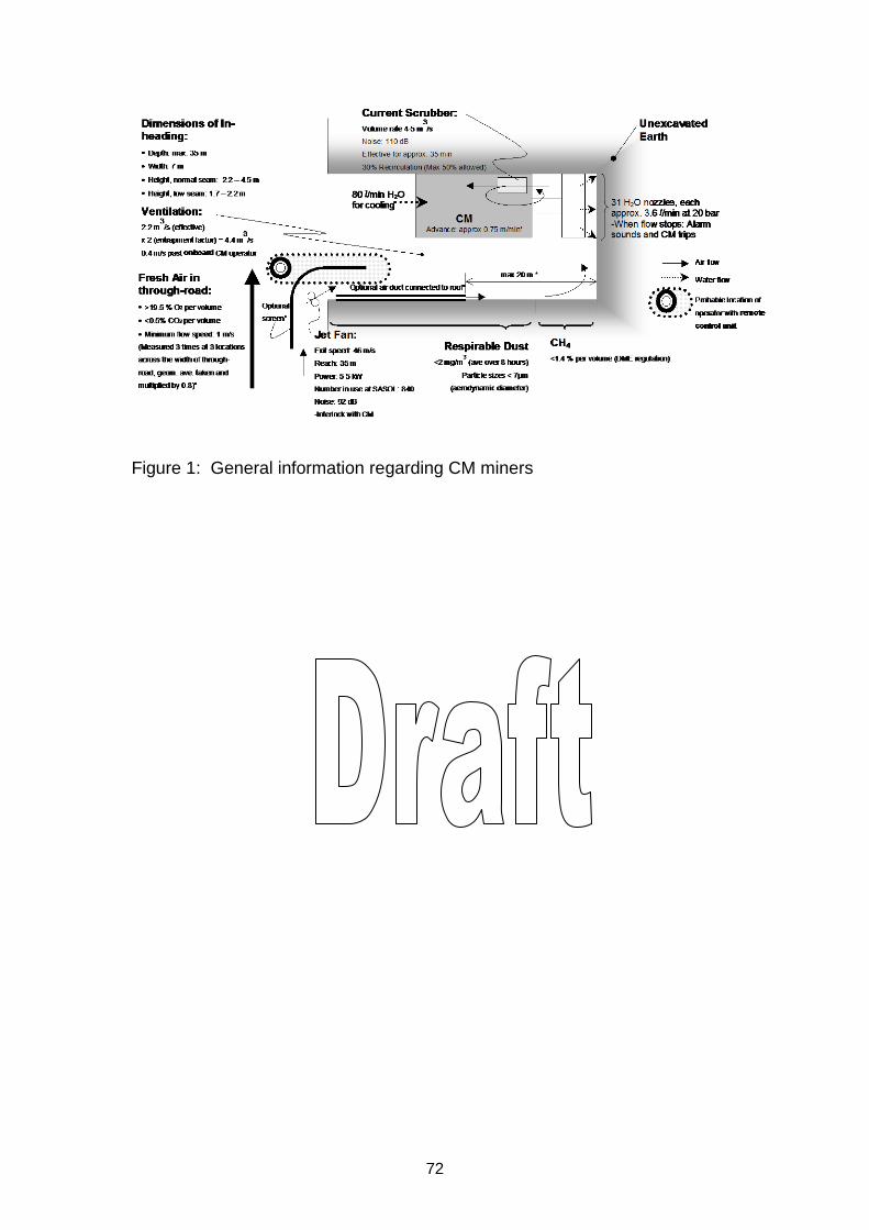
3.2 System specification
The draft specifications for the system are graphically shown in figure 3-1.
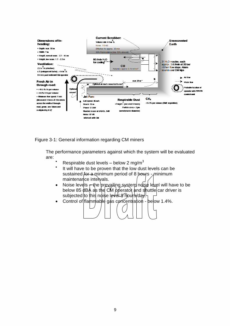
9
Figure 3-1: General information regarding CM miners
The performance parameters against which the system will be evaluated are:
Respirable dust levels – below 2 mg/m3
It will have to be proven that the low dust levels can be sustained for a minimum period of 8 hours - minimum maintenance intervals.
Noise levels – the prevailing system noise level will have to be below 85 dBA as the CM operator and shuttle car driver is subjected to this noise level 8 hours/day.
Control of flammable gas concentration - below 1.4%.
10
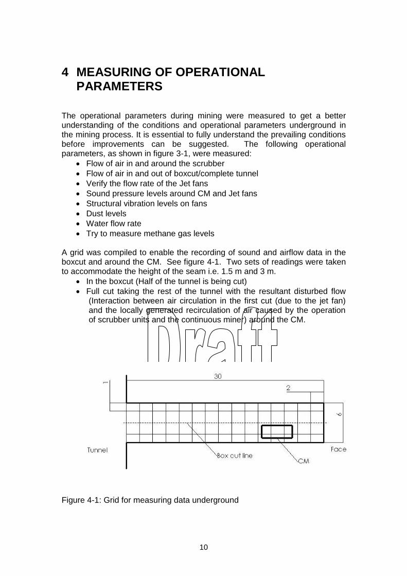
4 MEASURING OF OPERATIONAL PARAMETERS
The operational parameters during mining were measured to get a better understanding of the conditions and operational parameters underground in the mining process. It is essential to fully understand the prevailing conditions before improvements can be suggested. The following operational parameters, as shown in figure 3-1, were measured:
Flow of air in and around the scrubber
Flow of air in and out of boxcut/complete tunnel
Verify the flow rate of the Jet fans
Sound pressure levels around CM and Jet fans
Structural vibration levels on fans
Dust levels
Water flow rate
Try to measure methane gas levels
A grid was compiled to enable the recording of sound and airflow data in the boxcut and around the CM. See figure 4-1. Two sets of readings were taken to accommodate the height of the seam i.e. 1.5 m and 3 m.
In the boxcut (Half of the tunnel is being cut)
Full cut taking the rest of the tunnel with the resultant disturbed flow (Interaction between air circulation in the first cut (due to the jet fan) and the locally generated recirculation of air caused by the operation of scrubber units and the continuous miner) around the CM.
Figure 4-1: Grid for measuring data underground
11
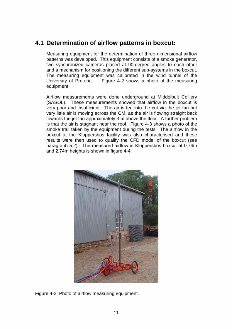
4.1 Determination of airflow patterns in boxcut:
Measuring equipment for the determination of three-dimensional airflow patterns was developed. This equipment consists of a smoke generator, two synchronized cameras placed at 90-degree angles to each other and a mechanism for positioning the different sub-systems in the boxcut. The measuring equipment was calibrated in the wind tunnel of the University of Pretoria. Figure 4-2 shows a photo of the measuring equipment.
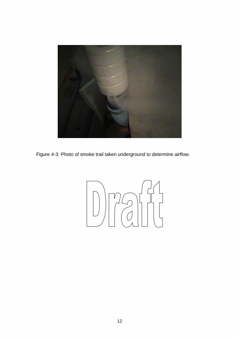
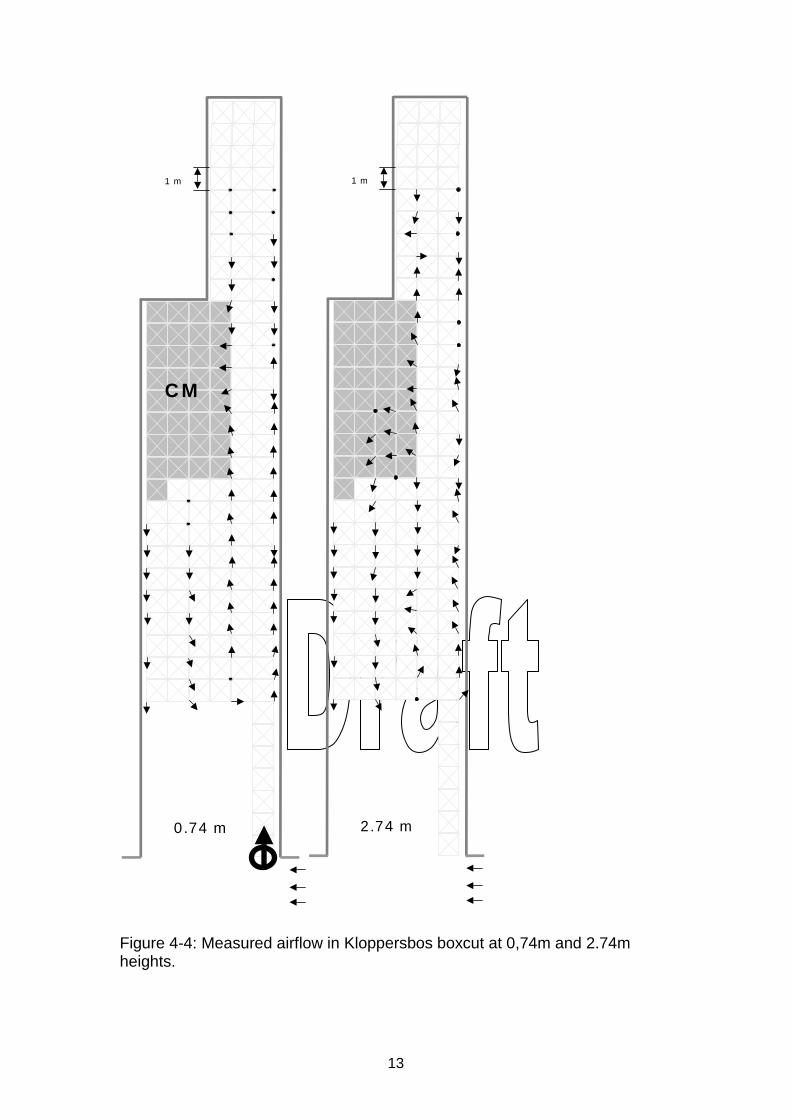
Airflow measurements were done underground at Middelbult Colliery (SASOL). These measurements showed that airflow in the boxcut is very poor and insufficient. The air is fed into the cut via the jet fan but very little air is moving across the CM, as the air is flowing straight back towards the jet fan approximately 3 m above the floor. A further problem is that the air is stagnant near the roof. Figure 4-3 shows a photo of the smoke trail taken by the equipment during the tests. The airflow in the boxcut at the Kloppersbos facility was also characterised and these results were then used to qualify the CFD model of the boxcut (see paragraph 5.2). The measured airflow in Kloppersbos boxcut at 0,74m and 2.74m heights is shown in figure 4-4.
Figure 4-2: Photo of airflow measuring equipment.
12
Figure 4-3: Photo of smoke trail taken underground to determine airflow.
13
0.74 m
C M
1 m
2.74 m
1 m
Figure 4-4: Measured airflow in Kloppersbos boxcut at 0,74m and 2.74m heights.
14
4.2 Underground dust measurements
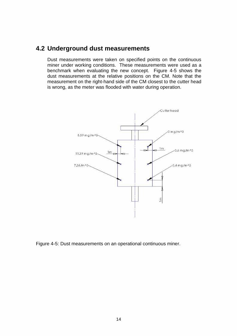
Dust measurements were taken on specified points on the continuous miner under working conditions. These measurements were used as a benchmark when evaluating the new concept. Figure 4-5 shows the dust measurements at the relative positions on the CM. Note that the measurement on the right-hand side of the CM closest to the cutter head is wrong, as the meter was flooded with water during operation.
Figure 4-5: Dust measurements on an operational continuous miner.
15
5 CONCEPT STUDY
Different concepts were generated making use of the results of the literature study, measurements taken underground as well as information from the workshops held with OEM’s, industry users and MHSC representatives. The efficiency of the different alternatives was then evaluated with Computational Fluid Dynamic (CFD) modelling. CFD modelling was then used to design the ventilation system around the continuous miner (CM).
5.1 Concept design
The following concepts were investigated to establish the possible success of each.
Solid particle separator – similar to the equipment sold by Donaldson
Water curtain – The work done by SASOL will have to be evaluated
Wethead – The work done by Anglo will have to evaluated
Additional fans to ensure continuous dilution of the methane gas
Surfactants.
Each of the mentioned concepts was evaluated to determine the possible success.
5.2 Preferred concept
To satisfy the different operational requirements a system approach was proposed. The preferred concept consists of the following systems:
Ventilation design (take positive control of airflow). Making use of the results of the CFD modelling the concept ventilation was designed (see paragraph 5.-3). The fan of the scrubber is connected to ducting which channels the air out of the boxcut. A jet fan positioned at the entrance of the boxcut forces fresh air into the boxcut.
Use of surfactants.
Redesigned scrubber making use of a rotating cloth, which is continuously cleaned by a water spray system.
16
5.3 Computational Fluid Dynamic (CFD) evaluations of alternatives
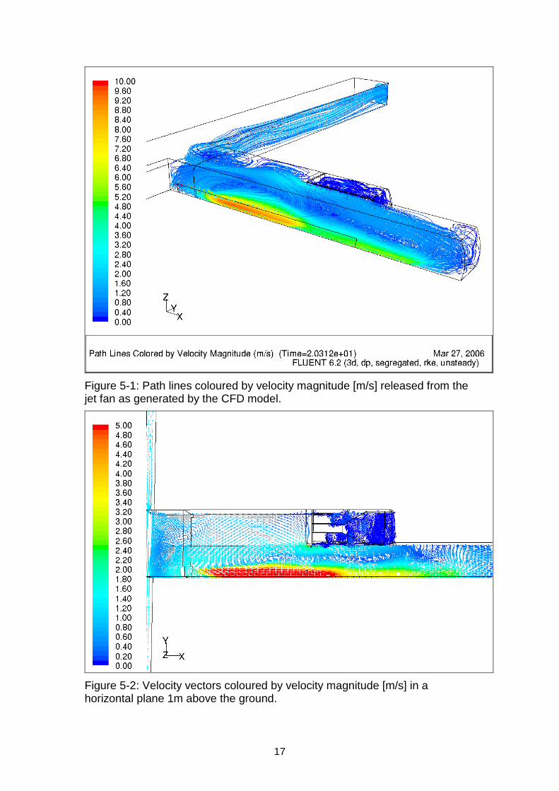
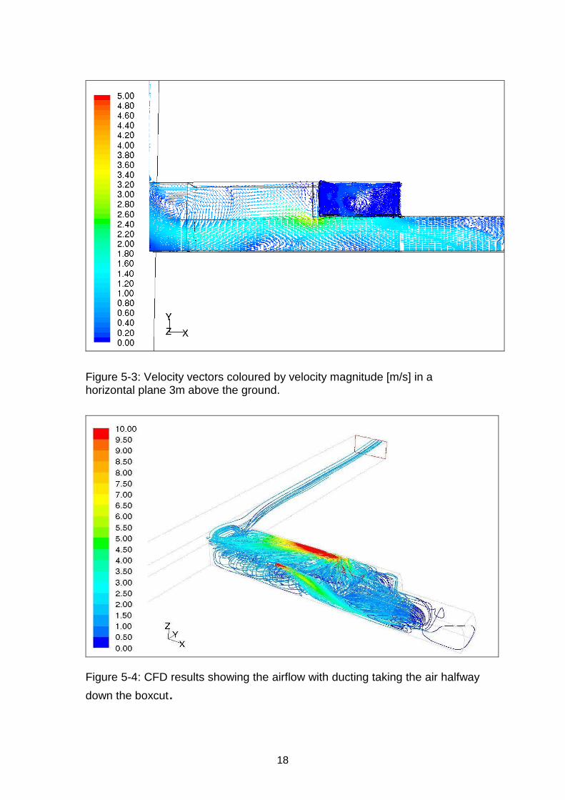
Computational Fluid Dynamic (CFD) modelling was used to evaluate different concepts and to design the ventilation system around the CM. The full report on the CFD modelling work is attached as Appendix B.
A CFD model of the Kloppersbos boxcut was built and the model was verified using the airflow measurements of the boxcut. This validated model was then used to evaluate the efficiency of the concepts (see paragraph 4.1). Figure 5-1 shows path lines coloured by velocity magnitude [m/s] released from the jet fan, as generated by the CFD model and figures 5-2 and 5-3 show the velocity vectors coloured by velocity magnitude [m/s] in a horizontal plane 1m and 3 m above the ground.
The results from the measurements and CFD modelling indicate the following:
Premature return of the ventilation air from the jet fan.
A recirculation zone in the deepest section of the duct suggests poor ventilation in this area.
A low velocity behind the continuous miner suggests poor ventilation in this area.
From these results it is evident that the current ventilation system does leave certain areas poorly ventilated.
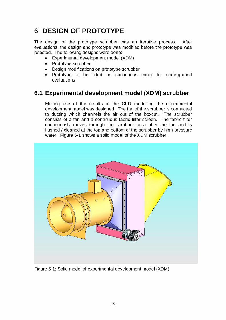
Computational Fluid Dynamic (CFD) modelling was done to determine airflow patterns of different ventilation designs. Simulations were done with different ducting taking the airflow into the boxcut. The results of the CFD modelling show that ventilation is insufficient if the air is forced into the boxcut. Figure 5-4 shows the airflow with ducting taking the air halfway down the boxcut.
Making use of the results of the CFD modelling the concept ventilation was designed. The fan of the scrubber is connected to ducting which channels the air out of the boxcut.
17
Figure 5-1: Path lines coloured by velocity magnitude [m/s] released from the jet fan as generated by the CFD model.
Figure 5-2: Velocity vectors coloured by velocity magnitude [m/s] in a horizontal plane 1m above the ground.
18
Figure 5-3: Velocity vectors coloured by velocity magnitude [m/s] in a horizontal plane 3m above the ground.
Figure 5-4: CFD results showing the airflow with ducting taking the air halfway
down the boxcut.
19
6 DESIGN OF PROTOTYPE
The design of the prototype scrubber was an iterative process. After evaluations, the design and prototype was modified before the prototype was retested. The following designs were done:
Experimental development model (XDM)
Prototype scrubber
Design modifications on prototype scrubber
Prototype to be fitted on continuous miner for underground evaluations
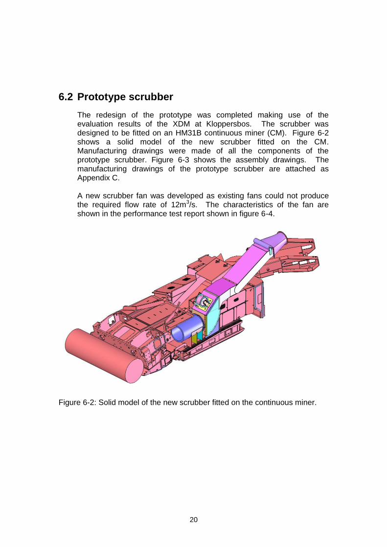
6.1 Experimental development model (XDM) scrubber
Making use of the results of the CFD modelling the experimental development model was designed. The fan of the scrubber is connected to ducting which channels the air out of the boxcut. The scrubber consists of a fan and a continuous fabric filter screen. The fabric filter continuously moves through the scrubber area after the fan and is flushed / cleaned at the top and bottom of the scrubber by high-pressure water. Figure 6-1 shows a solid model of the XDM scrubber.
Figure 6-1: Solid model of experimental development model (XDM)
20
6.2 Prototype scrubber
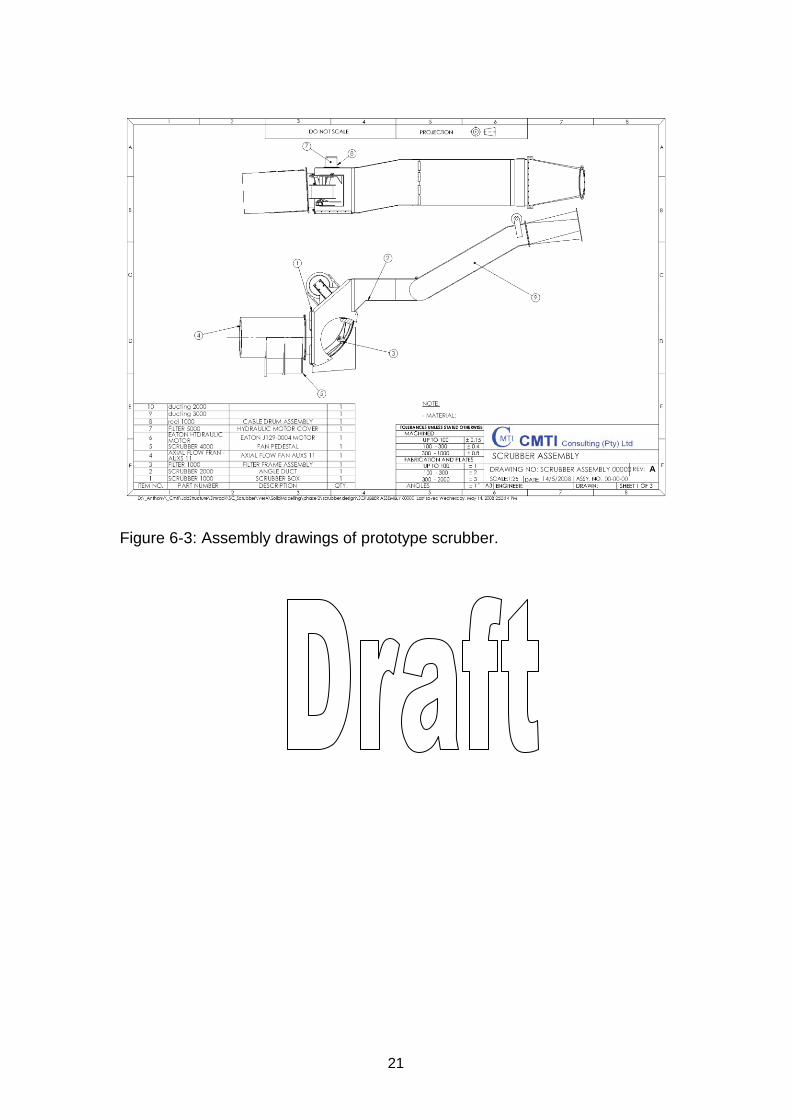
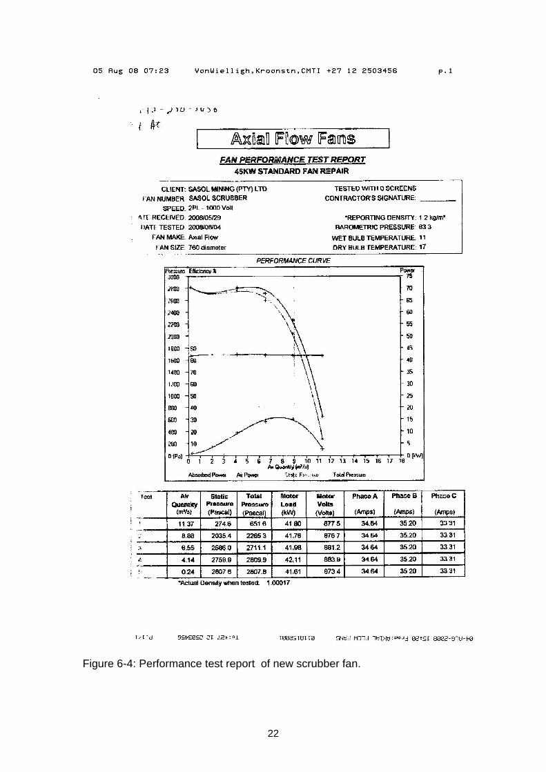
The redesign of the prototype was completed making use of the evaluation results of the XDM at Kloppersbos. The scrubber was designed to be fitted on an HM31B continuous miner (CM). Figure 6-2 shows a solid model of the new scrubber fitted on the CM. Manufacturing drawings were made of all the components of the prototype scrubber. Figure 6-3 shows the assembly drawings. The manufacturing drawings of the prototype scrubber are attached as Appendix C. A new scrubber fan was developed as existing fans could not produce the required flow rate of 12m3/s. The characteristics of the fan are shown in the performance test report shown in figure 6-4.
Figure 6-2: Solid model of the new scrubber fitted on the continuous miner.
21
Figure 6-3: Assembly drawings of prototype scrubber.
22
Figure 6-4: Performance test report of new scrubber fan.
23
6.3 Design modifications
Taking the results of the scrubber tests at Kloppersbos into consideration, the following design modifications were done:
Enlarge the scrubber outlet to an area of 0,45m².
Install a demister on scrubber outlet.
Redesign the cartridge instalment and alignment method.
Reduce the number of bolts on the side cover.
Enlarge the water drainage pipes.
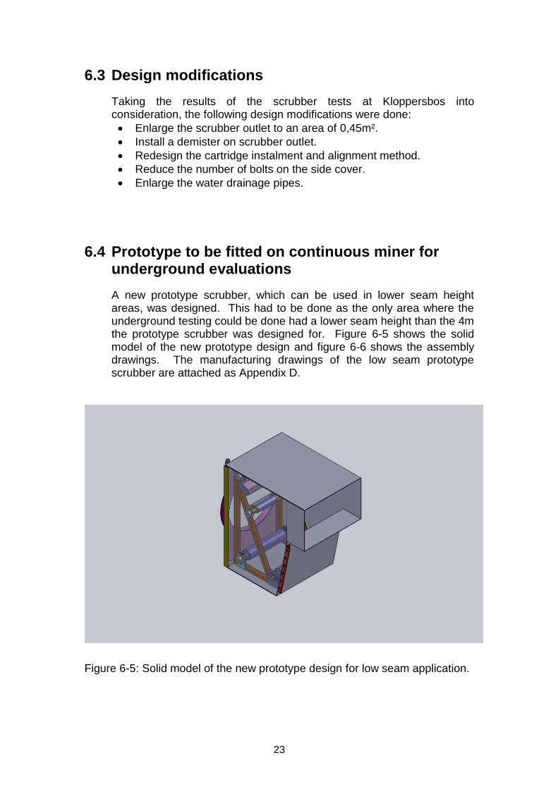
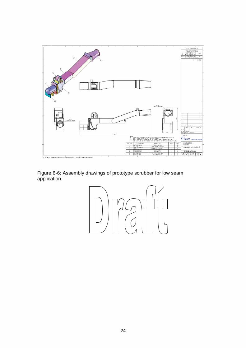
6.4 Prototype to be fitted on continuous miner for underground evaluations
A new prototype scrubber, which can be used in lower seam height areas, was designed. This had to be done as the only area where the underground testing could be done had a lower seam height than the 4m the prototype scrubber was designed for. Figure 6-5 shows the solid model of the new prototype design and figure 6-6 shows the assembly drawings. The manufacturing drawings of the low seam prototype scrubber are attached as Appendix D.
Figure 6-5: Solid model of the new prototype design for low seam application.
24
Figure 6-6: Assembly drawings of prototype scrubber for low seam application.
25
7 BUILD PROTOTYPE
Different prototype scrubber models were built.
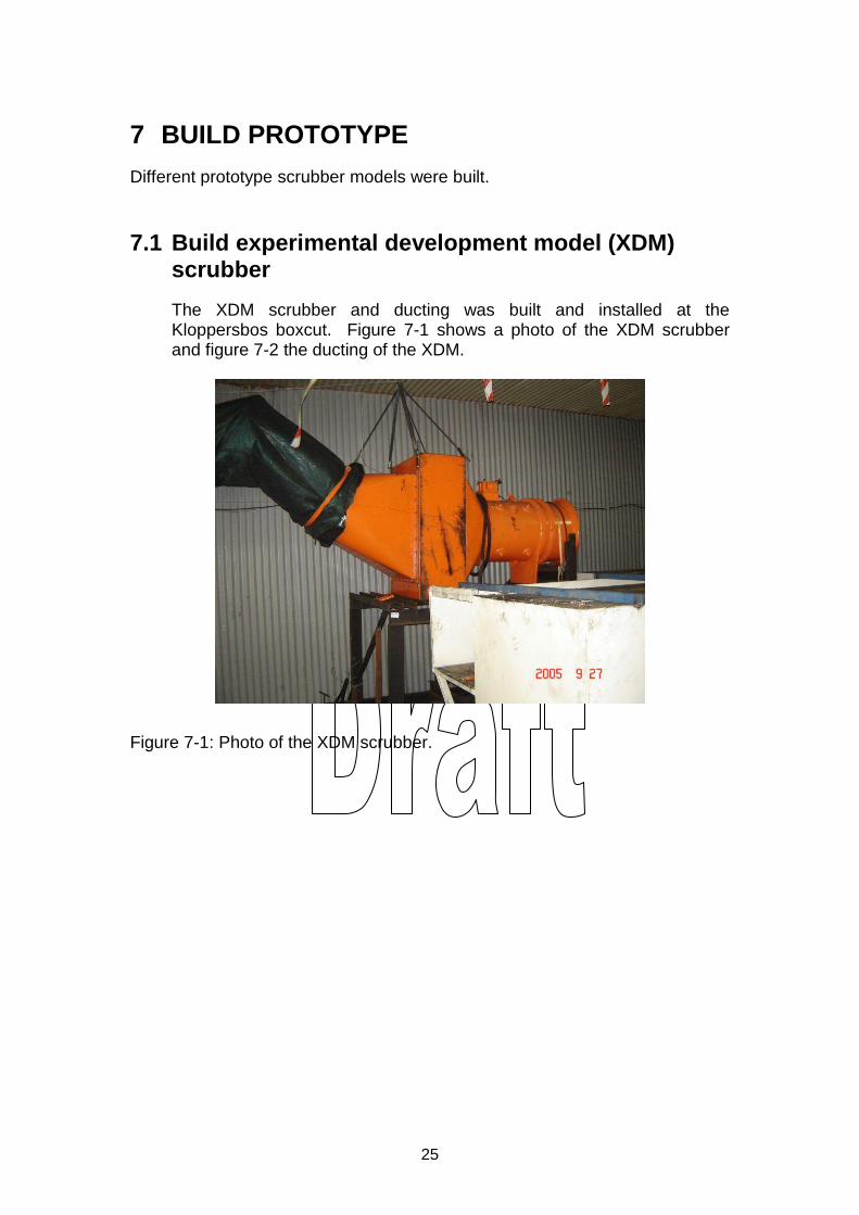
7.1 Build experimental development model (XDM) scrubber
The XDM scrubber and ducting was built and installed at the Kloppersbos boxcut. Figure 7-1 shows a photo of the XDM scrubber and figure 7-2 the ducting of the XDM.
Figure 7-1: Photo of the XDM scrubber.
26
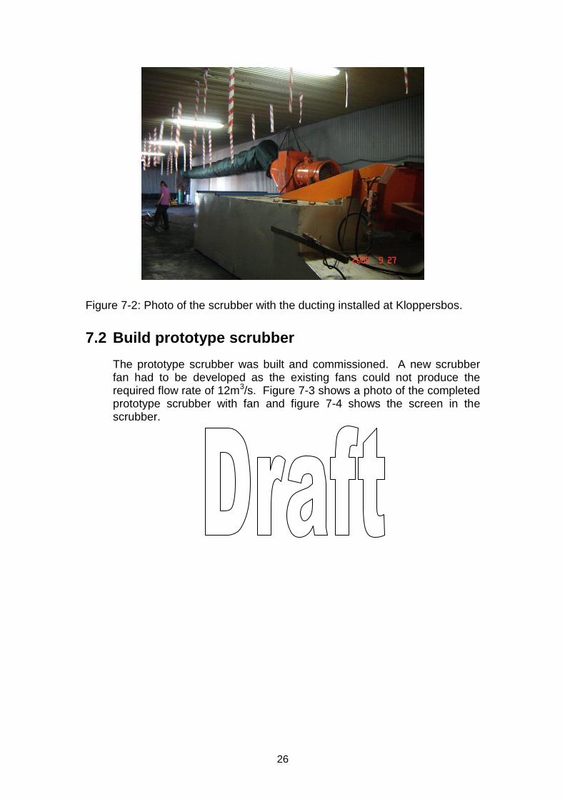
Figure 7-2: Photo of the scrubber with the ducting installed at Kloppersbos.
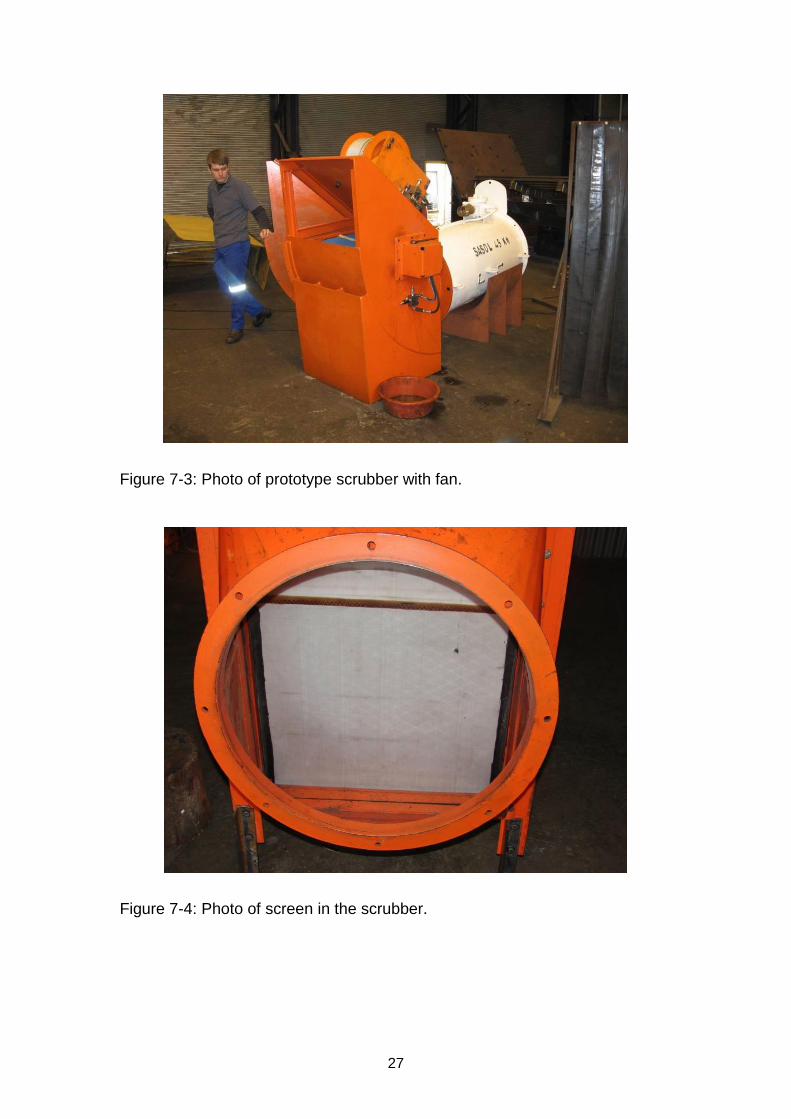
7.2 Build prototype scrubber
The prototype scrubber was built and commissioned. A new scrubber fan had to be developed as the existing fans could not produce the required flow rate of 12m3/s. Figure 7-3 shows a photo of the completed prototype scrubber with fan and figure 7-4 shows the screen in the scrubber.
27
Figure 7-3: Photo of prototype scrubber with fan.
Figure 7-4: Photo of screen in the scrubber.
28
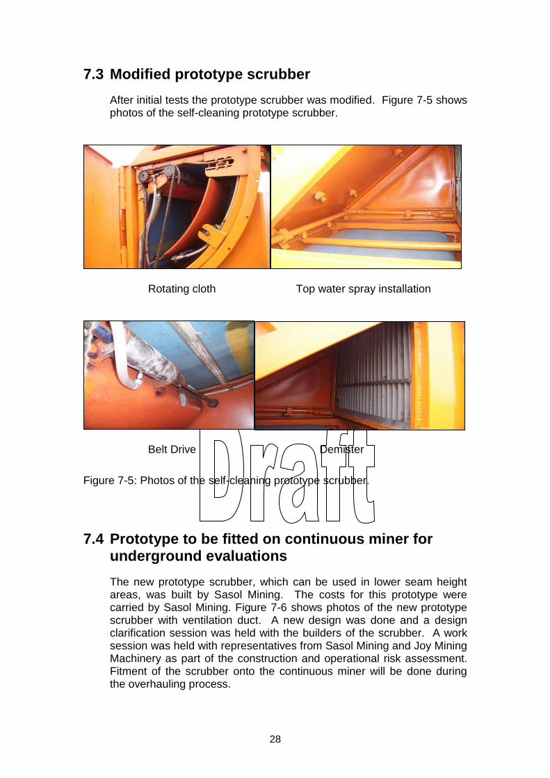
7.3 Modified prototype scrubber
After initial tests the prototype scrubber was modified. Figure 7-5 shows photos of the self-cleaning prototype scrubber.
Rotating cloth Top water spray installation
Belt Drive Demister
Figure 7-5: Photos of the self-cleaning prototype scrubber.
7.4 Prototype to be fitted on continuous miner for underground evaluations
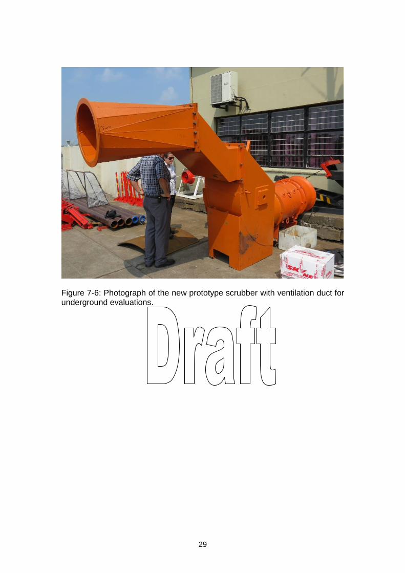
The new prototype scrubber, which can be used in lower seam height areas, was built by Sasol Mining. The costs for this prototype were carried by Sasol Mining. Figure 7-6 shows photos of the new prototype scrubber with ventilation duct. A new design was done and a design clarification session was held with the builders of the scrubber. A work session was held with representatives from Sasol Mining and Joy Mining Machinery as part of the construction and operational risk assessment. Fitment of the scrubber onto the continuous miner will be done during the overhauling process.
29
Figure 7-6: Photograph of the new prototype scrubber with ventilation duct for underground evaluations.
30
8 SURFACE TESTING
The surface testing was done at Kloppersbos. The experimental development model (XDM), the prototype scrubber, as well as the modified prototype scrubber were tested. The following tests were performed:
Functionality tests of system
Dust suppression tests
Ventilation tests o Smoke tests o Ventilation: Speed and direction
Methane dilution tests
Surfactant tests
8.1 Test of experimental development model (XDM):
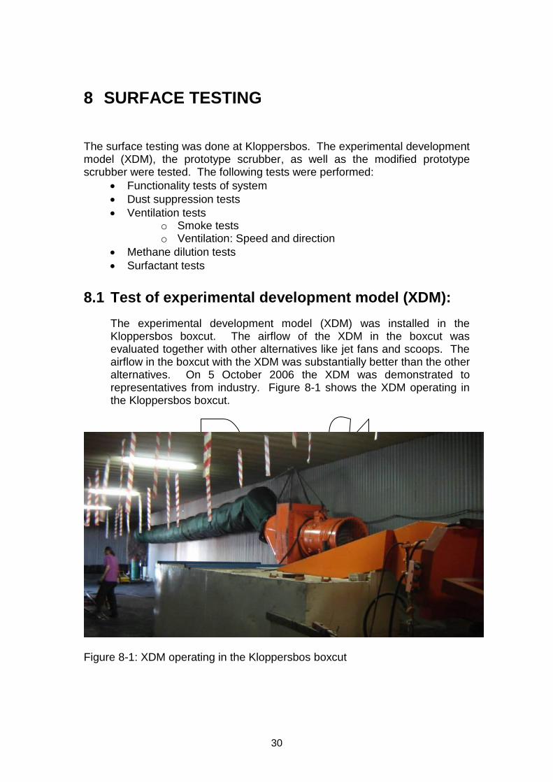
The experimental development model (XDM) was installed in the Kloppersbos boxcut. The airflow of the XDM in the boxcut was evaluated together with other alternatives like jet fans and scoops. The airflow in the boxcut with the XDM was substantially better than the other alternatives. On 5 October 2006 the XDM was demonstrated to representatives from industry. Figure 8-1 shows the XDM operating in the Kloppersbos boxcut.
Figure 8-1: XDM operating in the Kloppersbos boxcut
31
.
8.2 Dust Measurements
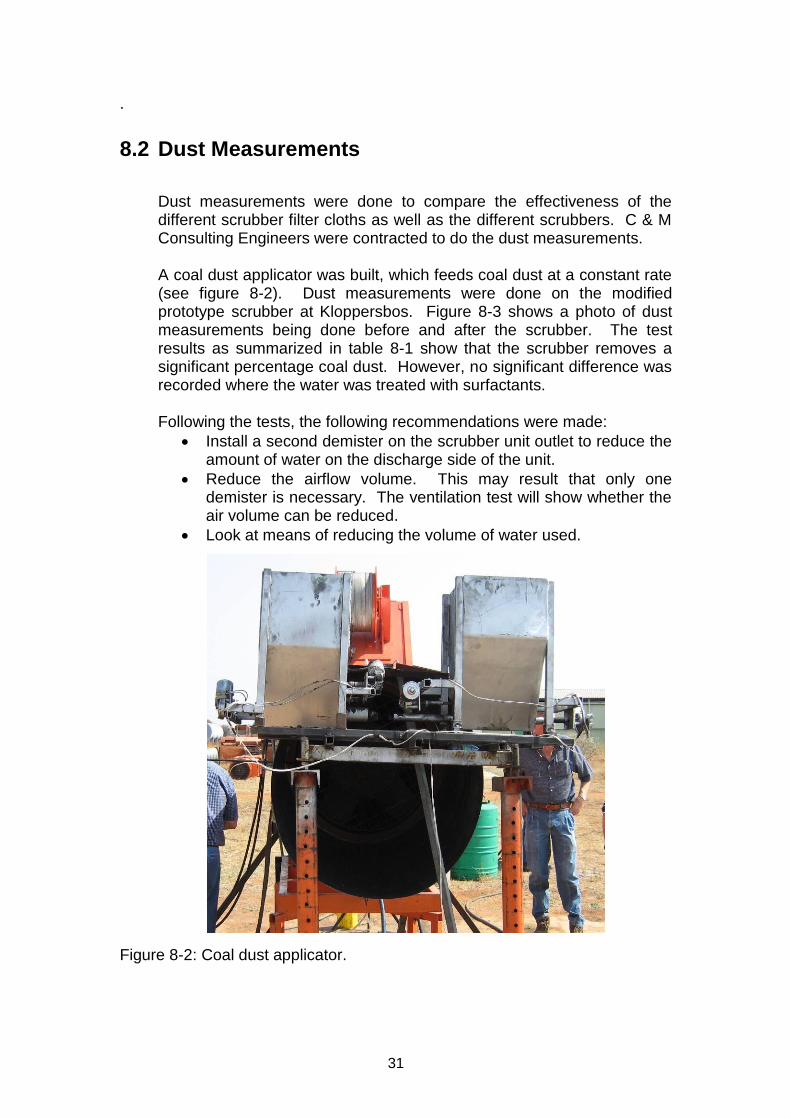
Dust measurements were done to compare the effectiveness of the different scrubber filter cloths as well as the different scrubbers. C & M Consulting Engineers were contracted to do the dust measurements.
A coal dust applicator was built, which feeds coal dust at a constant rate (see figure 8-2). Dust measurements were done on the modified prototype scrubber at Kloppersbos. Figure 8-3 shows a photo of dust measurements being done before and after the scrubber. The test results as summarized in table 8-1 show that the scrubber removes a significant percentage coal dust. However, no significant difference was recorded where the water was treated with surfactants.
Following the tests, the following recommendations were made:
Install a second demister on the scrubber unit outlet to reduce the amount of water on the discharge side of the unit.
Reduce the airflow volume. This may result that only one demister is necessary. The ventilation test will show whether the air volume can be reduced.
Look at means of reducing the volume of water used.
Figure 8-2: Coal dust applicator.
32
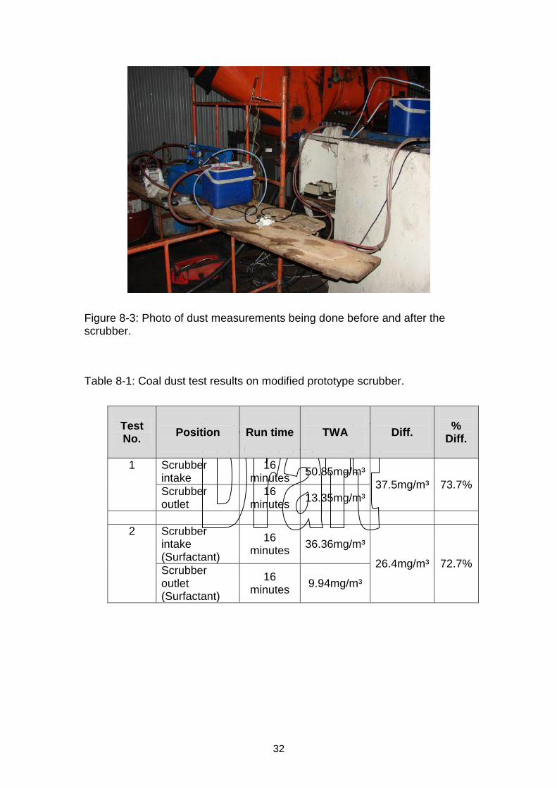
Figure 8-3: Photo of dust measurements being done before and after the scrubber.
Table 8-1: Coal dust test results on modified prototype scrubber.
Test No.
Position
Run time
TWA
Diff.
%
Diff.
1 Scrubber intake
16 minutes
50.85mg/m³ 37.5mg/m³ 73.7%
Scrubber outlet
16 minutes
13.35mg/m³
2 Scrubber intake (Surfactant)
16 minutes
36.36mg/m³
26.4mg/m³ 72.7% Scrubber outlet (Surfactant)
16 minutes
9.94mg/m³
33
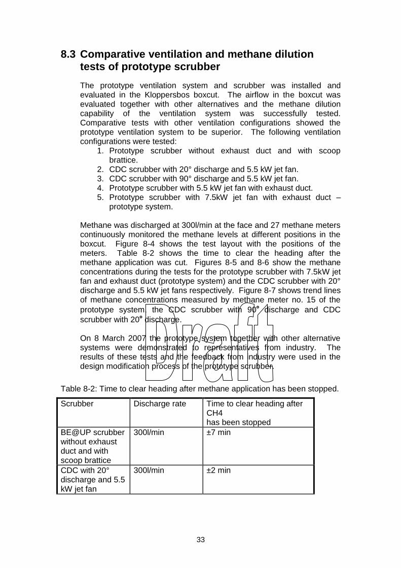
8.3 Comparative ventilation and methane dilution tests of prototype scrubber
The prototype ventilation system and scrubber was installed and evaluated in the Kloppersbos boxcut. The airflow in the boxcut was evaluated together with other alternatives and the methane dilution capability of the ventilation system was successfully tested. Comparative tests with other ventilation configurations showed the prototype ventilation system to be superior. The following ventilation configurations were tested:
1. Prototype scrubber without exhaust duct and with scoop brattice.
2. CDC scrubber with 20° discharge and 5.5 kW jet fan. 3. CDC scrubber with 90° discharge and 5.5 kW jet fan. 4. Prototype scrubber with 5.5 kW jet fan with exhaust duct. 5. Prototype scrubber with 7.5kW jet fan with exhaust duct –
prototype system.
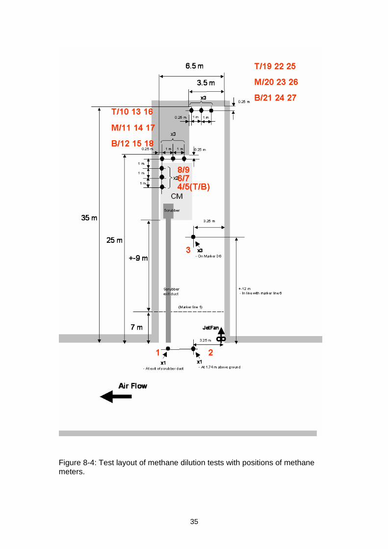
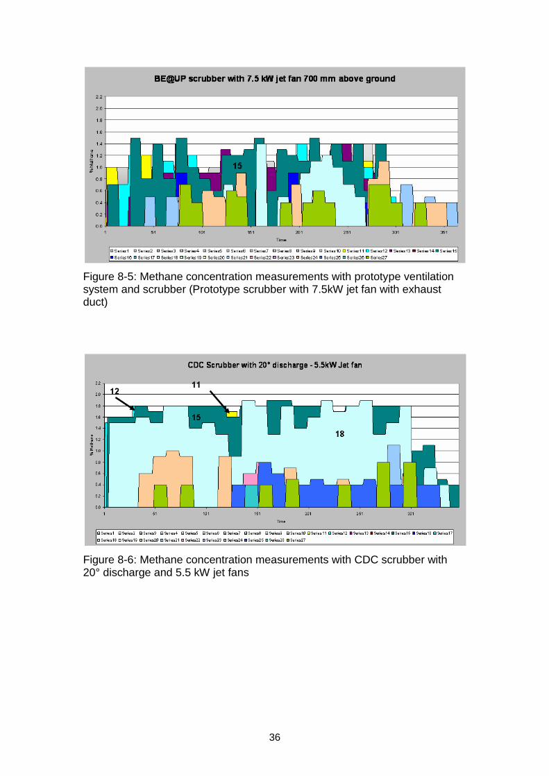
Methane was discharged at 300l/min at the face and 27 methane meters continuously monitored the methane levels at different positions in the boxcut. Figure 8-4 shows the test layout with the positions of the meters. Table 8-2 shows the time to clear the heading after the methane application was cut. Figures 8-5 and 8-6 show the methane concentrations during the tests for the prototype scrubber with 7.5kW jet fan and exhaust duct (prototype system) and the CDC scrubber with 20° discharge and 5.5 kW jet fans respectively. Figure 8-7 shows trend lines of methane concentrations measured by methane meter no. 15 of the
prototype system, the CDC scrubber with 90° discharge and CDC
scrubber with 20° discharge.
On 8 March 2007 the prototype system together with other alternative systems were demonstrated to representatives from industry. The results of these tests and the feedback from industry were used in the design modification process of the prototype scrubber.
Table 8-2: Time to clear heading after methane application has been stopped.
Scrubber Discharge rate Time to clear heading after CH4 has been stopped
BE@UP scrubber without exhaust duct and with scoop brattice
300l/min ±7 min
CDC with 20° discharge and 5.5 kW jet fan
300l/min ±2 min
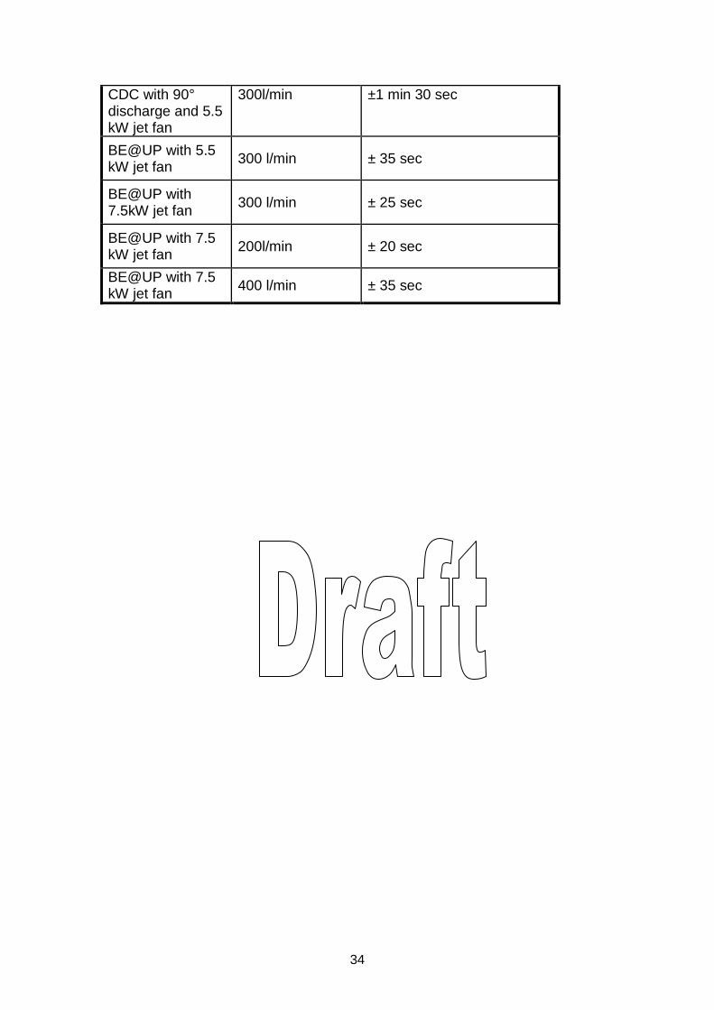
34
CDC with 90° discharge and 5.5 kW jet fan
300l/min ±1 min 30 sec
BE@UP with 5.5 kW jet fan
300 l/min ± 35 sec
BE@UP with 7.5kW jet fan
300 l/min ± 25 sec
BE@UP with 7.5 kW jet fan
200l/min ± 20 sec
BE@UP with 7.5 kW jet fan
400 l/min ± 35 sec
35
Figure 8-4: Test layout of methane dilution tests with positions of methane meters.
36
Figure 8-5: Methane concentration measurements with prototype ventilation system and scrubber (Prototype scrubber with 7.5kW jet fan with exhaust duct)
Figure 8-6: Methane concentration measurements with CDC scrubber with 20° discharge and 5.5 kW jet fans
37
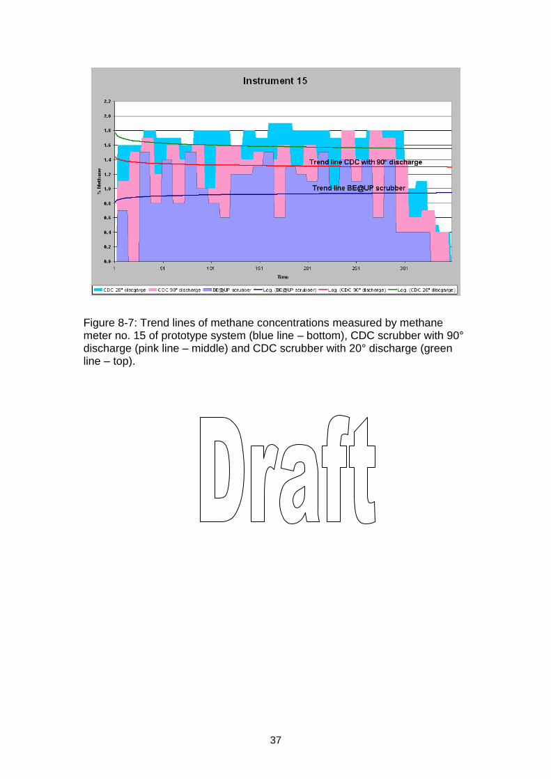
Figure 8-7: Trend lines of methane concentrations measured by methane meter no. 15 of prototype system (blue line – bottom), CDC scrubber with 90° discharge (pink line – middle) and CDC scrubber with 20° discharge (green line – top).
38
8.4 Comprehensive ventilation and methane dilution testing of modified prototype scrubber with CM
A Continuous Miner (CM) was brought to Kloppersbos for the testing of the modified prototype scrubber. Comparative tests were done between the modified scrubber, the CDC scrubber and the “Twin scrubber”. The different comparative tests were decided on together with industry.
8.4.1 Test
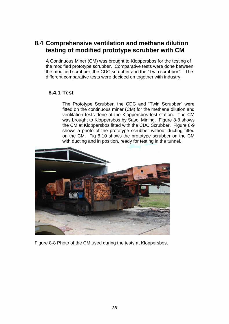
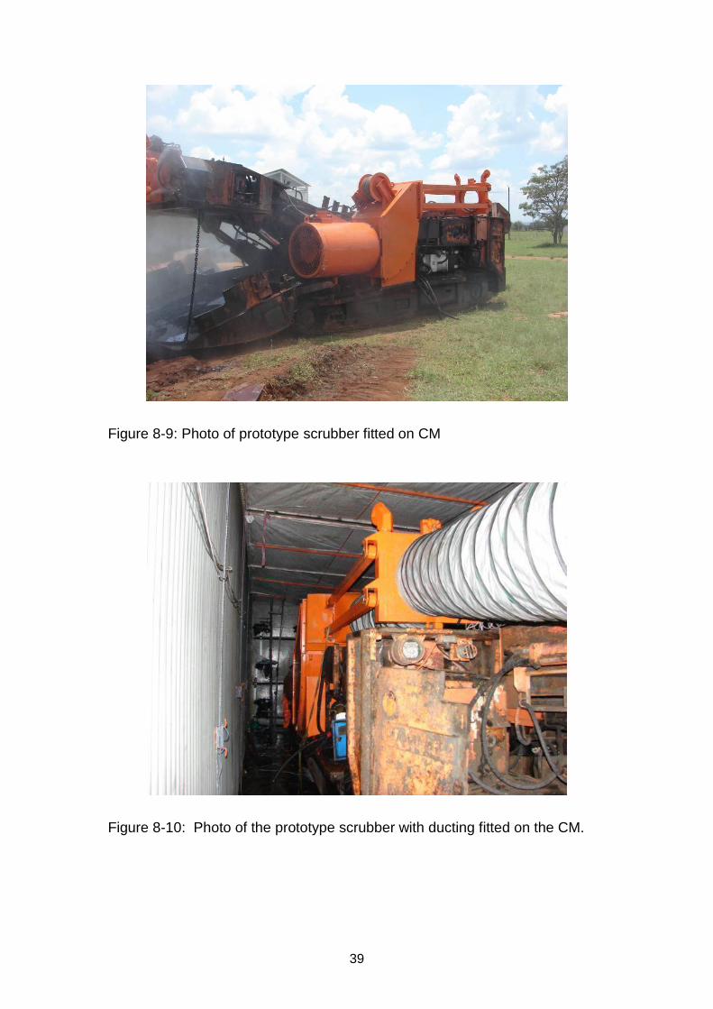
The Prototype Scrubber, the CDC and “Twin Scrubber” were fitted on the continuous miner (CM) for the methane dilution and ventilation tests done at the Kloppersbos test station. The CM was brought to Kloppersbos by Sasol Mining. Figure 8-8 shows the CM at Kloppersbos fitted with the CDC Scrubber. Figure 8-9 shows a photo of the prototype scrubber without ducting fitted on the CM. Fig 8-10 shows the prototype scrubber on the CM with ducting and in position, ready for testing in the tunnel.
Figure 8-8 Photo of the CM used during the tests at Kloppersbos.
39
Figure 8-9: Photo of prototype scrubber fitted on CM
Figure 8-10: Photo of the prototype scrubber with ducting fitted on the CM.
40
8.4.1.1 Tests
Comparative ventilation and methane dilution tests were done with each of the following combinations:
• Scrubber – CDC scrubber – Prototype scrubber – Twin scrubber
• Roof height – High (3.5m) – Low (2.2m)
• Water curtain – On – Off
• Wethead – On – Off
• Position of cutter head – Top – Bottom
8.4.1.2 Instrumentation
8.4.1.2.1 Ventilation tests
A smoke generator with adjustable height discharge was used to release smoke at predetermined positions. The direction of the smoke was recorded and photo and video records were kept. Figure 8-11 shows the points where the ventilation was recorded and Figure 8-12 shows photos of the mobile smoke generator.
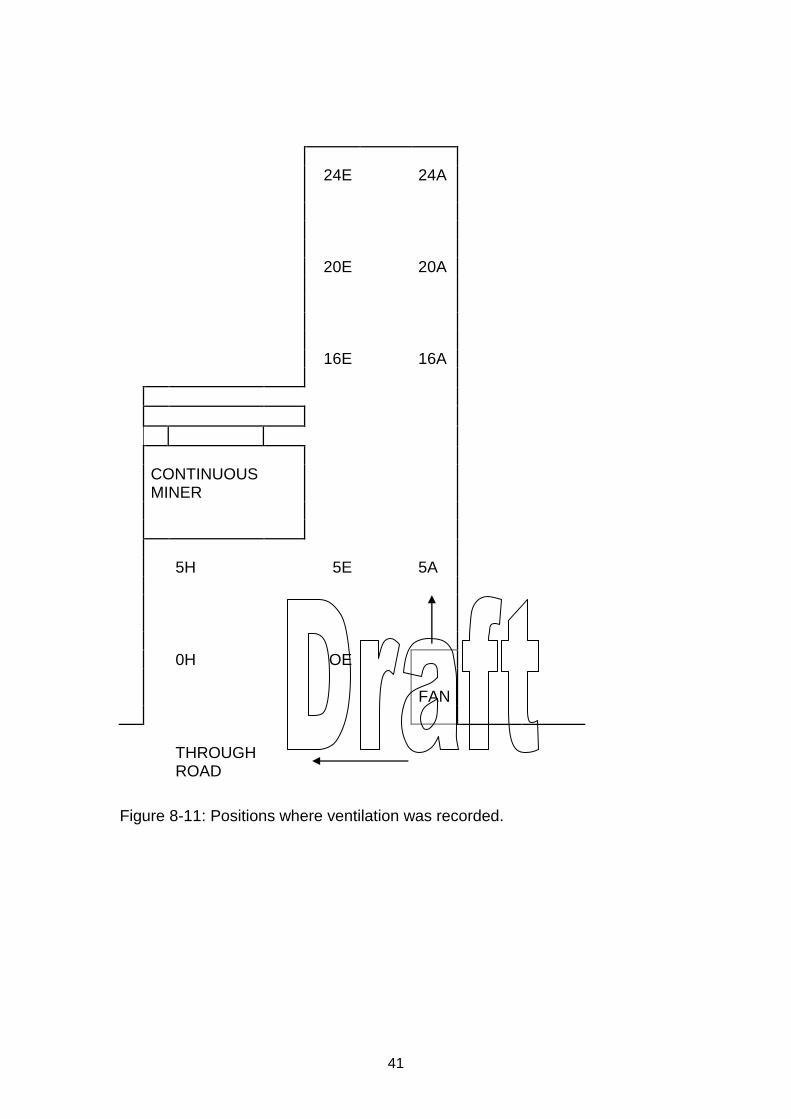
41
24E 24A 20E 20A 16E 16A
CONTINUOUS MINER
5H 5E 5A
0H OE FAN
THROUGH ROAD
Figure 8-11: Positions where ventilation was recorded.
42
Figure 8-12: Photos of the mobile smoke generator
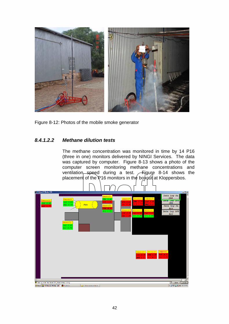
8.4.1.2.2 Methane dilution tests
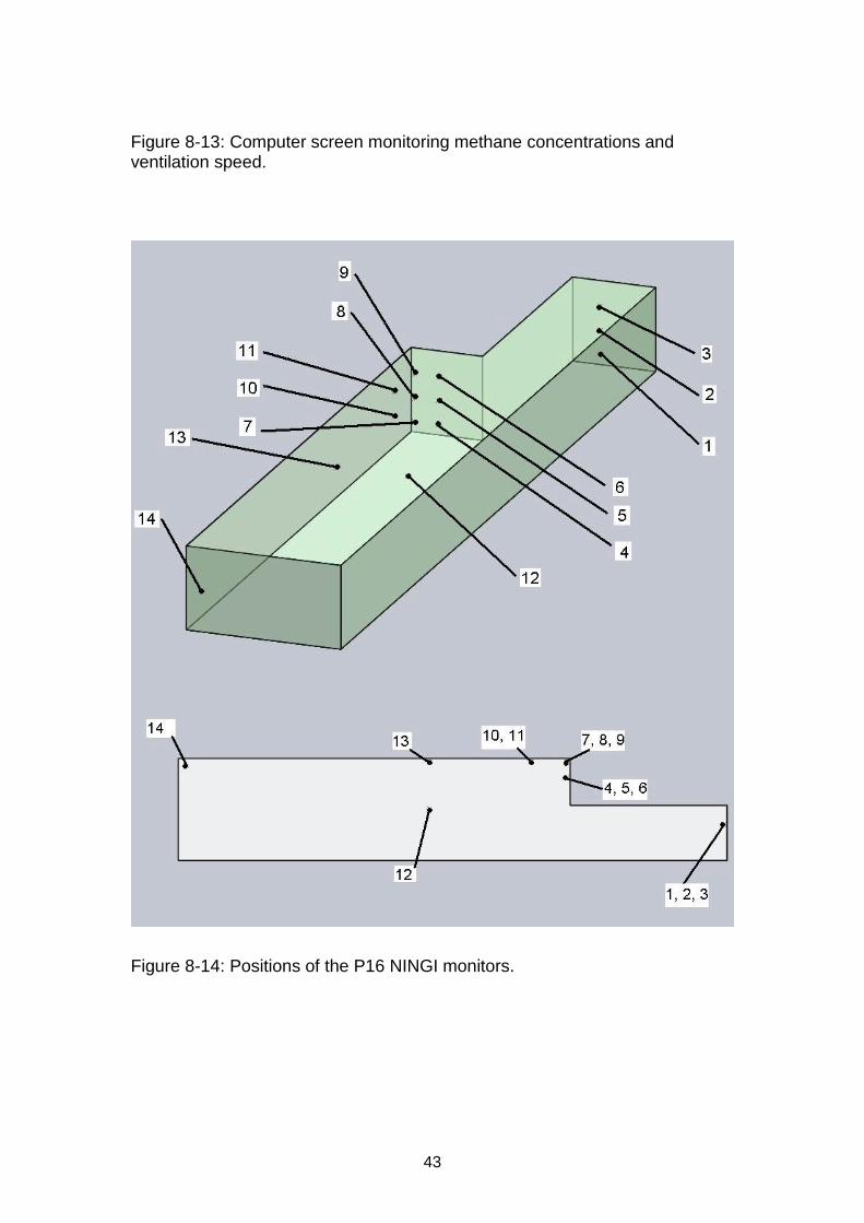
The methane concentration was monitored in time by 14 P16 (three in one) monitors delivered by NINGI Services. The data was captured by computer. Figure 8-13 shows a photo of the computer screen monitoring methane concentrations and ventilation speed during a test. Figure 8-14 shows the placement of the P16 monitors in the boxcut at Kloppersbos.
43
Figure 8-13: Computer screen monitoring methane concentrations and ventilation speed.
Figure 8-14: Positions of the P16 NINGI monitors.
44
8.4.2 Tests procedure
8.4.2.1 Smoke test
The evaluation of the ventilation was done by releasing smoke at predetermined points. The smoke was released at a height of 1m from the floor, in the middle and 1m below the roof where the direction of the airflow was recorded. The build-up of smoke, which is an indication of the ventilation efficiency, was also recorded.
8.4.2.2 Methane dilution
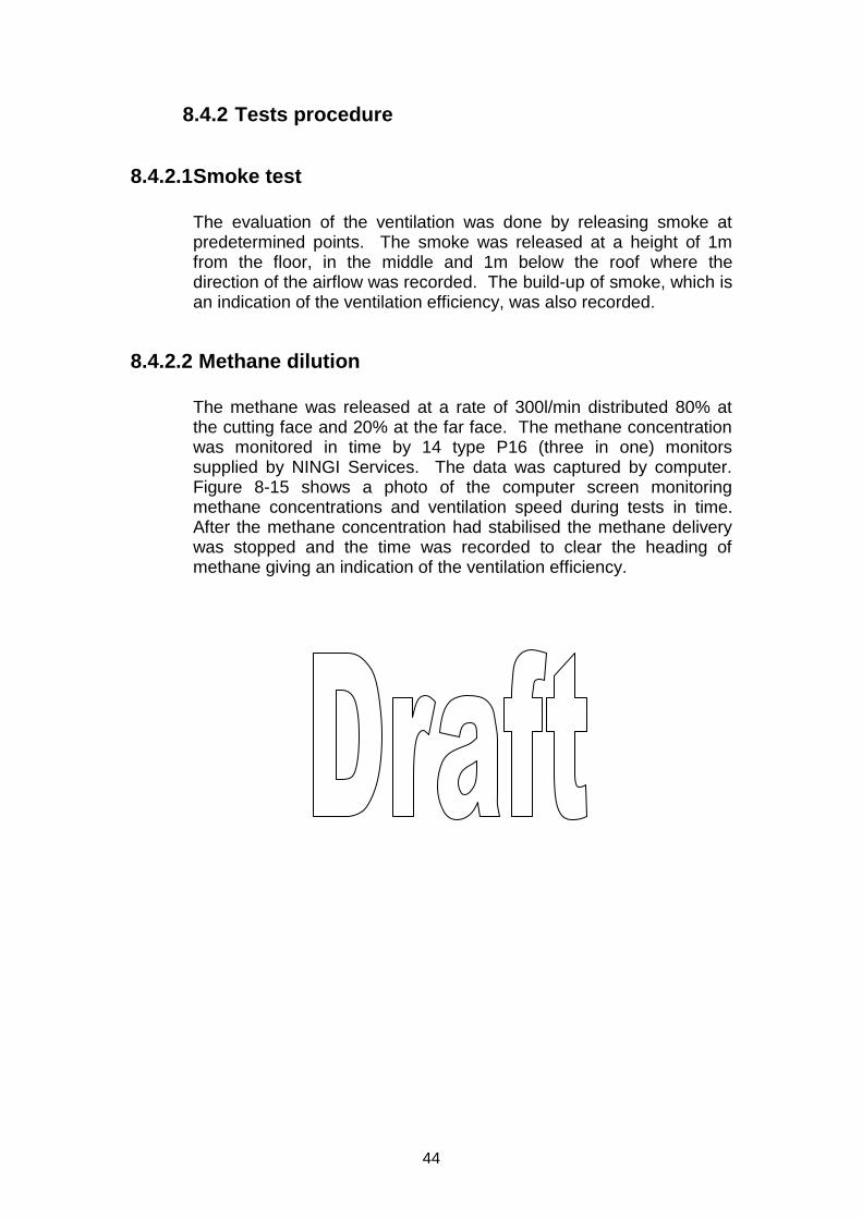
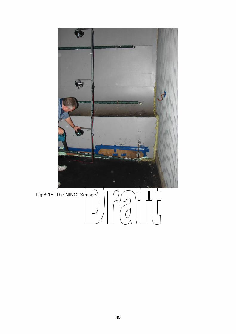
The methane was released at a rate of 300l/min distributed 80% at the cutting face and 20% at the far face. The methane concentration was monitored in time by 14 type P16 (three in one) monitors supplied by NINGI Services. The data was captured by computer. Figure 8-15 shows a photo of the computer screen monitoring methane concentrations and ventilation speed during tests in time. After the methane concentration had stabilised the methane delivery was stopped and the time was recorded to clear the heading of methane giving an indication of the ventilation efficiency.
45
.
Fig 8-15: The NINGI Sensors
46
8.4.3 Test results
8.4.3.1 Ventilation tests (Smoke tests)
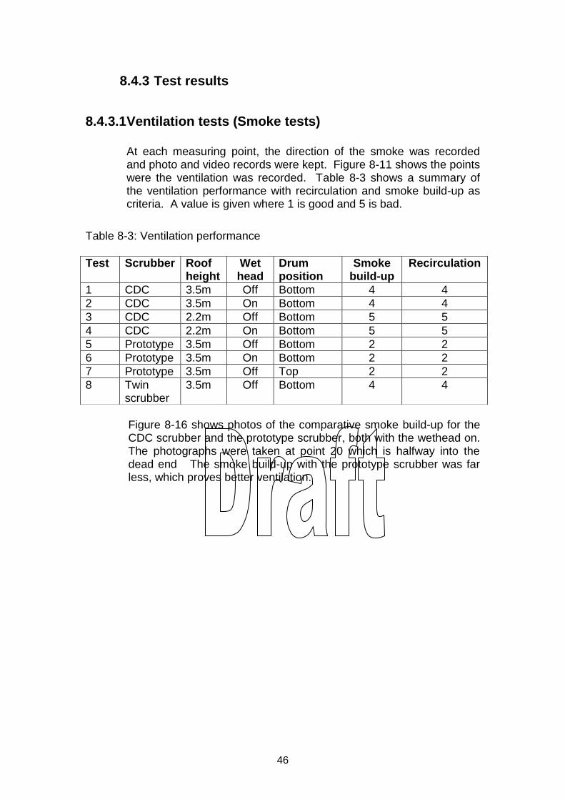
At each measuring point, the direction of the smoke was recorded and photo and video records were kept. Figure 8-11 shows the points were the ventilation was recorded. Table 8-3 shows a summary of the ventilation performance with recirculation and smoke build-up as criteria. A value is given where 1 is good and 5 is bad.
Table 8-3: Ventilation performance
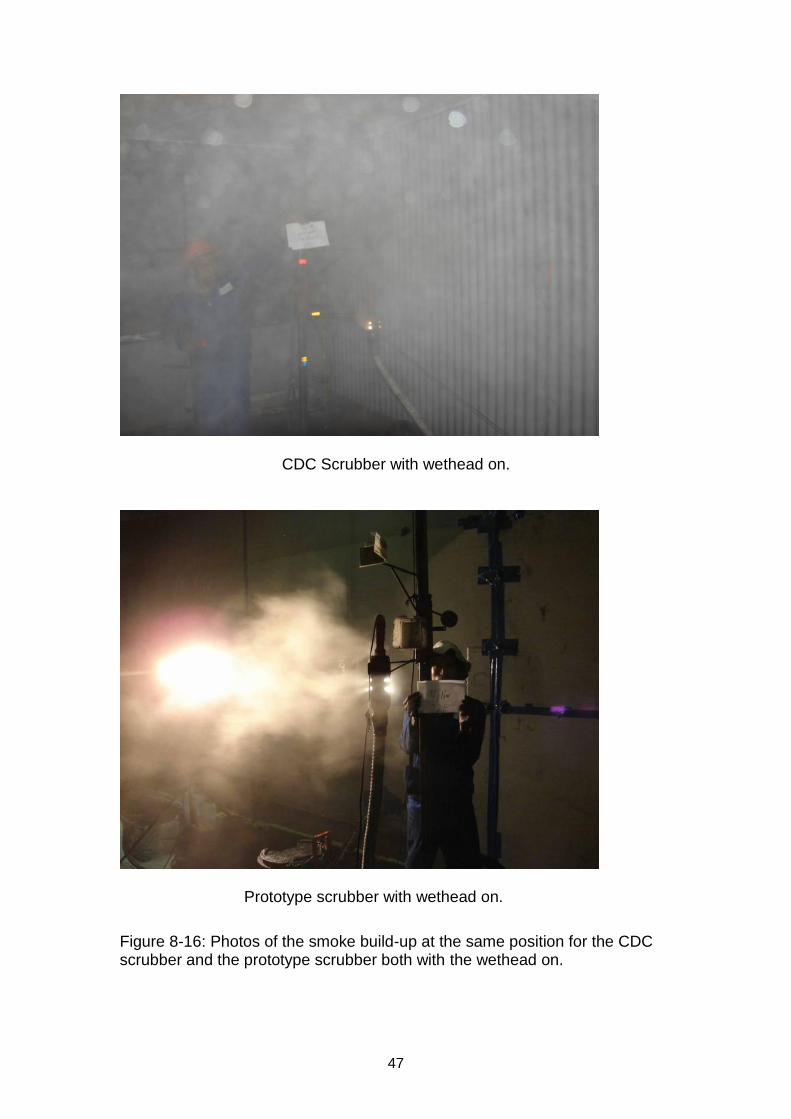
Figure 8-16 shows photos of the comparative smoke build-up for the CDC scrubber and the prototype scrubber, both with the wethead on. The photographs were taken at point 20 which is halfway into the dead end The smoke build-up with the prototype scrubber was far less, which proves better ventilation.
Test Scrubber Roof height
Wet head
Drum position
Smoke build-up
Recirculation
1 CDC 3.5m Off Bottom 4 4
2 CDC 3.5m On Bottom 4 4
3 CDC 2.2m Off Bottom 5 5
4 CDC 2.2m On Bottom 5 5
5 Prototype 3.5m Off Bottom 2 2
6 Prototype 3.5m On Bottom 2 2
7 Prototype 3.5m Off Top 2 2
8 Twin scrubber
3.5m Off Bottom 4 4
47
CDC Scrubber with wethead on.
Prototype scrubber with wethead on.
Figure 8-16: Photos of the smoke build-up at the same position for the CDC scrubber and the prototype scrubber both with the wethead on.
48
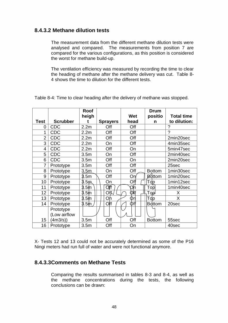
8.4.3.2 Methane dilution tests
The measurement data from the different methane dilution tests were analysed and compared. The measurements from position 7 are compared for the various configurations, as this position is considered the worst for methane build-up.
The ventilation efficiency was measured by recording the time to clear the heading of methane after the methane delivery was cut. Table 8-4 shows the time to dilution for the different tests.
Table 8-4: Time to clear heading after the delivery of methane was stopped.
Test Scrubber
Roof heigh
t Sprayers Wet head
Drum positio
n Total time to dilution:
0 CDC 2.2m Off Off ?
1 CDC 2.2m Off Off ?
2 CDC 2.2m Off Off 2min20sec
3 CDC 2.2m On Off 4min35sec
4 CDC 2.2m Off On 5min47sec
5 CDC 3.5m On Off 2min40sec
6 CDC 3.5m Off On 2min20sec
7 Prototype 3.5m Off Off 25sec
8 Prototype 3.5m On Off Bottom 1min30sec
9 Prototype 3.5m Off On Bottom 1min20sec
10 Prototype 3.5m On Off Top 1min12sec
11 Prototype 3.5m Off On Top 1min40sec
12 Prototype 3.5m Off Off Top X
13 Prototype 3.5m On On Top X
14 Prototype 3.5m Off Off Bottom 20sec
15
Prototype (Low airflow (4m3/s)) 3.5m Off Off Bottom 55sec
16 Prototype 3.5m Off On 40sec
X- Tests 12 and 13 could not be accurately determined as some of the P16 Ningi meters had run full of water and were not functional anymore.
8.4.3.3 Comments on Methane Tests
Comparing the results summarised in tables 8-3 and 8-4, as well as the methane concentrations during the tests, the following conclusions can be drawn:
49
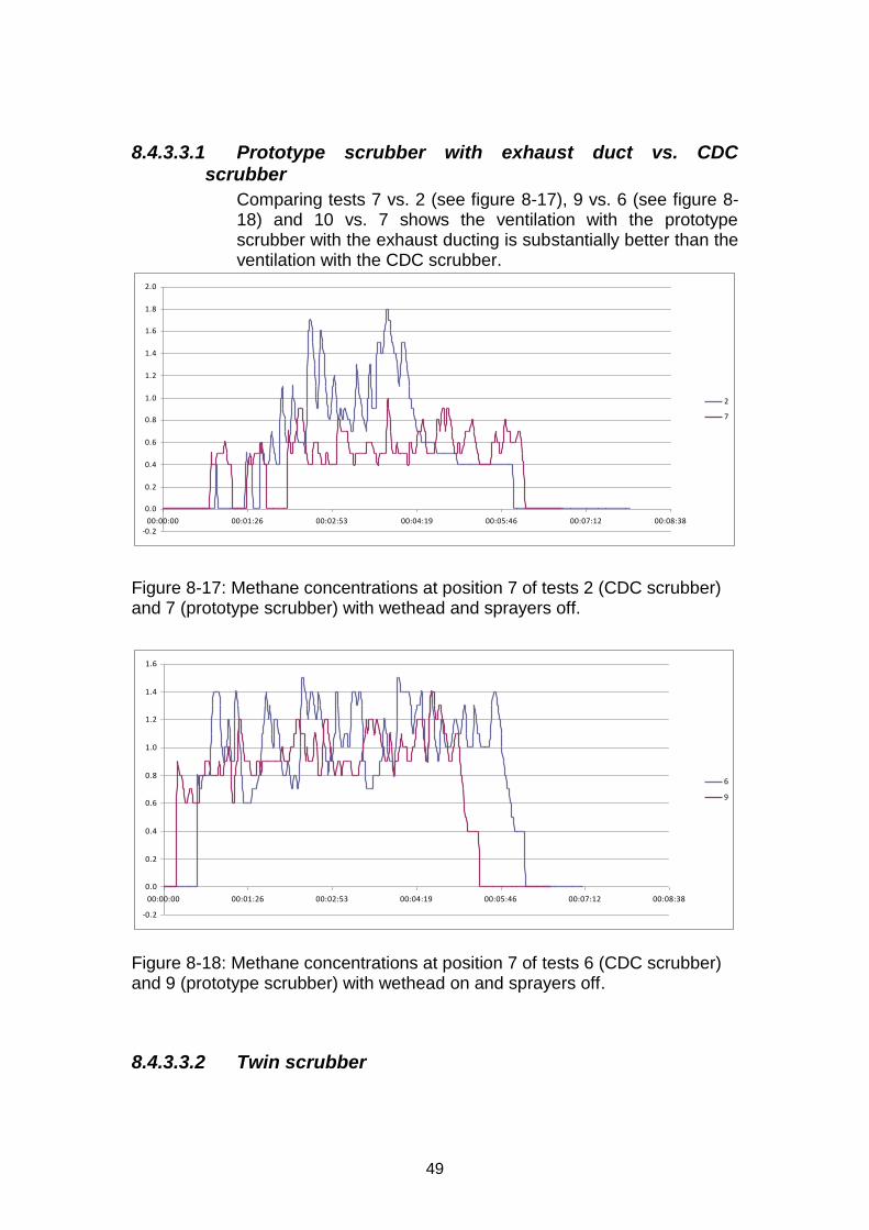
8.4.3.3.1 Prototype scrubber with exhaust duct vs. CDC scrubber
Comparing tests 7 vs. 2 (see figure 8-17), 9 vs. 6 (see figure 8-18) and 10 vs. 7 shows the ventilation with the prototype scrubber with the exhaust ducting is substantially better than the ventilation with the CDC scrubber.
-0.2
0.0
0.2
0.4
0.6
0.8
1.0
1.2
1.4
1.6
1.8
2.0
00:00:00 00:01:26 00:02:53 00:04:19 00:05:46 00:07:12 00:08:38
2
7
Figure 8-17: Methane concentrations at position 7 of tests 2 (CDC scrubber) and 7 (prototype scrubber) with wethead and sprayers off.
-0.2
0.0
0.2
0.4
0.6
0.8
1.0
1.2
1.4
1.6
00:00:00 00:01:26 00:02:53 00:04:19 00:05:46 00:07:12 00:08:38
6
9
Figure 8-18: Methane concentrations at position 7 of tests 6 (CDC scrubber) and 9 (prototype scrubber) with wethead on and sprayers off.
8.4.3.3.2 Twin scrubber
50
From the results in Table 8-3 it can be seen that the ventilation performance of the twin scrubber is very similar to that of the CDC scrubber.
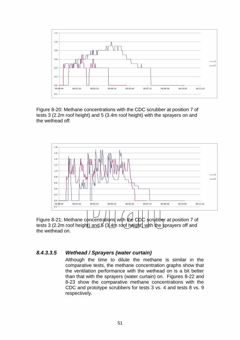
8.4.3.3.3 Scrubber fan capacity (test 15 vs. 16)
Although the total time to dilution of the prototype scrubber with a reduced displacement (4 m3/s) is longer than the time with full displacement (6 m3/s) the methane concentration at measuring point 7 is somewhat lower with the lower fan displacement (see figure 8-19). This shows that a lower displacement fan can most probably be used without substantially reducing the performance of the scrubber.
-0.2
0.0
0.2
0.4
0.6
0.8
1.0
1.2
1.4
1.6
00:00:00 00:01:26 00:02:53 00:04:19 00:05:46 00:07:12 00:08:38 00:10:05
16
15
Figure 8-19: Methane concentrations at position 7 of tests 15 (prototype scrubber with 4 m3/s) and 16 (prototype scrubber with 6 m3/s).
8.4.3.3.4 Roof height
The ventilation with the 3.4m roof height is better than that with the 2.2m roof height. Figures 8-20 and 8-21 show the methane concentrations for the 2.2m and 3.4m roof heights with the CDC and prototype scrubbers respectively.
51
-0.2
0.0
0.2
0.4
0.6
0.8
1.0
1.2
00:00:00 00:01:26 00:02:53 00:04:19 00:05:46 00:07:12 00:08:38 00:10:05 00:11:31
3
5
Figure 8-20: Methane concentrations with the CDC scrubber at position 7 of tests 3 (2.2m roof height) and 5 (3.4m roof height) with the sprayers on and the wethead off.
-0.2
0.0
0.2
0.4
0.6
0.8
1.0
1.2
1.4
1.6
1.8
00:00:00 00:01:26 00:02:53 00:04:19 00:05:46 00:07:12 00:08:38 00:10:05 00:11:31
4
6
Figure 8-21: Methane concentrations with the CDC scrubber at position 7 of tests 3 (2.2m roof height) and 5 (3.4m roof height) with the sprayers off and the wethead on.
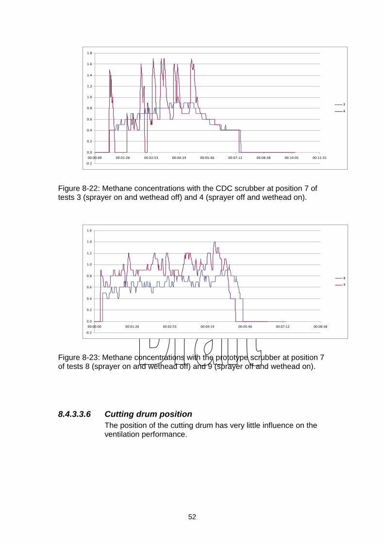
8.4.3.3.5 Wethead / Sprayers (water curtain)
Although the time to dilute the methane is similar in the comparative tests, the methane concentration graphs show that the ventilation performance with the wethead on is a bit better than that with the sprayers (water curtain) on. Figures 8-22 and 8-23 show the comparative methane concentrations with the CDC and prototype scrubbers for tests 3 vs. 4 and tests 8 vs. 9 respectively.
52
-0.2
0.0
0.2
0.4
0.6
0.8
1.0
1.2
1.4
1.6
1.8
00:00:00 00:01:26 00:02:53 00:04:19 00:05:46 00:07:12 00:08:38 00:10:05 00:11:31
3
4
Figure 8-22: Methane concentrations with the CDC scrubber at position 7 of tests 3 (sprayer on and wethead off) and 4 (sprayer off and wethead on).
-0.2
0.0
0.2
0.4
0.6
0.8
1.0
1.2
1.4
1.6
00:00:00 00:01:26 00:02:53 00:04:19 00:05:46 00:07:12 00:08:38
8
9
Figure 8-23: Methane concentrations with the prototype scrubber at position 7 of tests 8 (sprayer on and wethead off) and 9 (sprayer off and wethead on).
8.4.3.3.6 Cutting drum position
The position of the cutting drum has very little influence on the ventilation performance.
53
8.4.4 Conclusions
The ventilation and methane dilution test results show the comparative performances of the different scrubbers, as well as the comparative performances of the different operational conditions tested. The results can be summarised as follows:
The performance of the prototype scrubber is substantially better than the other scrubbers tested. The main reason for this is the exhaust ducting that prohibits recirculation.
The ventilation performance of the twin scrubber is similar to that of the CDC scrubber.
As the ventilation performance of the prototype scrubber with a reduced displacement of 4m3/s is only somewhat lower than that of the prototype with a displacement of 6 m3/s, a lower displacement fan can most probably be used without substantially reducing the performance of the scrubber.
The ventilation with the 3.4m roof height is better than that with the 2.2m roof height.
Similar ventilation performances were recorded with the wethead on or off.
The ventilation performances with the wethead on are slightly better than with the sprayers on (water curtain).
The position of the cutting drum has little influence on the ventilation performance.
54
9 INVETSIGATIONS INTO OPRATIONAL ASPECTS AND ALTERNATIVE SCRUBBER PLACEMENT
At a workshop with industry, it was requested that certain operational questions in connection with the possible underground operation of the new scrubber / ventilation system be investigated.
9.1 Negating first cut with new scrubber concept
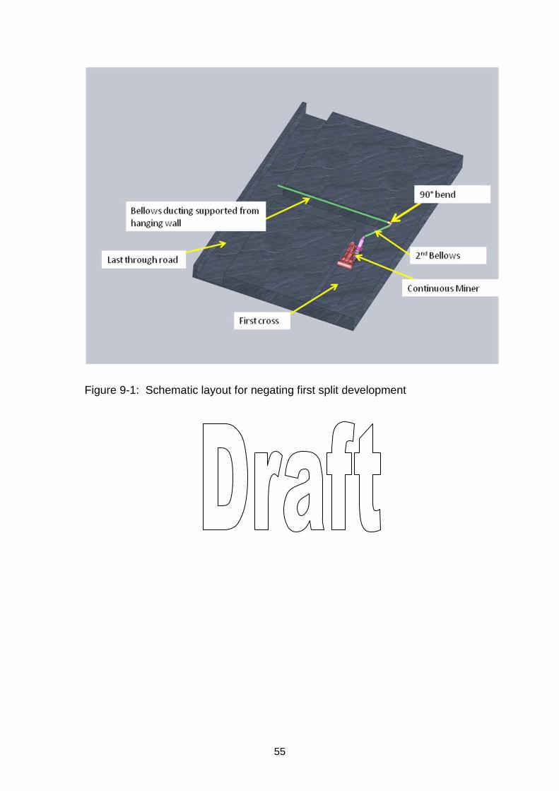
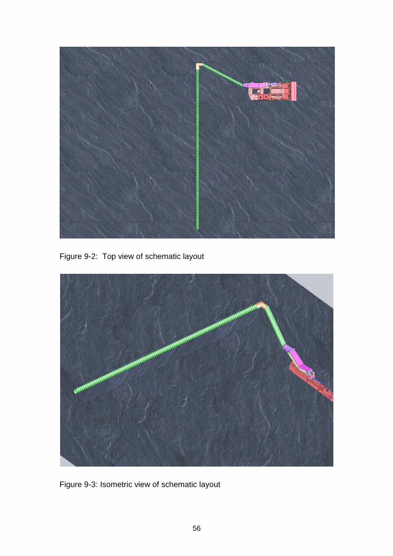
The mechanical miner is mining the roadway as normal while the ventilation ducting is suspended from the roof making use of the existing roof bolts. The maximum extension of the ventilation ducting down the normal heading is 35 m and the delivery end of the duct extends into the last through-road. When doing the first split development, the ventilation duct that enabled the cutting of the original heading will already be in place. It is then connected to a 90° bend suspended from the roof. The 90° bend is mounted in the back corner of the intersection. This will allow the duct to be mounted in such a way that it will be totally out of the way of the CM’s chain feeder as well as the shuttle cars. From the intersection a second ducting is mounted connecting the 90º bend to the scrubber mounted on the continuous miner. This duct is now coming in at an angle that will prevent the ducting from interfering with the chain feeder or the shuttle cars. Figures 9-1 to 9-3 show a schematic layout of the operation of performing the first split development.
55
Figure 9-1: Schematic layout for negating first split development
56
Figure 9-2: Top view of schematic layout
Figure 9-3: Isometric view of schematic layout
57
9.2 Balance between the jet fan and exhaust fan (scrubber fan)
A normal rule of thumb factor that is used in the coalmines, is that the jet fan must supply air in a ratio of 1 – 1,5 to 2 of the delivery of the scrubber fan. The request was made to discuss the validity of this rule of thumb with the suggested new scrubber. The proposed new scrubber system operates on the principle that air is taken from the cutting head area of the Continuous Miner (CM). The air is then cleaned through a self-cleaning scrubber system. The exhaust of this new scrubber is then ducted with a flexible duct to the last through-road, where the air is discharged into the ventilation air stream. The aim of this system is to positively ventilate the working area of the Continuous Miner (CM) With the jet fan some entrainment of surrounding air is obtained, due to the high velocity of the discharged air stream. This means that the total delivery from the jet fan system is more than the nett delivery of the jet fan itself. With the new system, where a duct is used to physically remove the air from the operating end of the CM to the through-road, positive ventilation is provided with no chance of re-circulation of the exhaust air. Tests conducted at Kloppersbos indicated that it is still beneficial to have the jet fan provide air to the front of the CM, as it positively assists the circulation. The new scrubber system then removes the dirty air from the operating end of the CM and discharges this air in the through-road.
Although the jet fan still serves a useful purpose, the ratio of 1 ½ is considered not that critical anymore, but in general it is considered that the ratios be kept at the values presently in service.
9.3 Positioning of the scrubber in the last through-road
The positioning of the scrubber in the last through-road aspect was considered at the beginning of this research project. The system of
58
having an off board scrubber was however ruled out for the following reasons:
The scrubber is a heavy piece of equipment requiring electricity to drive the fan and water to do the cleaning of the exhaust air. This means that the supply of these commodities would then be needed on the CM as well as on the scrubber in the through-road.
With the scrubber being a heavy piece of equipment, it would not be easy to suspend the scrubber from the roof of the working area and the ducting to connect the scrubber to the moving CM will pose a problem. If the scrubber is standing on the floor, the ducting will be damaged by the shuttle cars etc.
Another more important aspect is the fact that, whenever the scrubber is taken away from the CM, it would mean that the inlet air through the fan would be ducted from the operating area of the CM to the scrubber fan. This would mean that the air would have to be sucked away from the CM over some distance. The result of this suction process would be, that the pressure inside the ducting would be lower than atmospheric. Whenever the slightest denting of this flexible ducting occurs, the ducting would collapse and buckle due to the external pressure from the atmosphere. This would jeopardise the whole exercise.
When air is sucked through a section of ducting in this way, the pressure loss on the inlet would seriously affect the performance of the scrubber fan.
It is more effective to put the fan as close to the source of the inlet air and to put the fan behind the air and push the air out through the outlet ducting. (In laymen’s terms: It is better to push a ball of chewing gum than to pull the ball away from where it is sitting. If pulled, the chewing gum will just expand and it will be difficult to move the ball around. However, if the ball is pushed, the ball will be more easily displaced.)
Due to the above, it was decided that it is more efficient to put the scrubber on the CM and have the exhaust air from the CM taken away by means of flexible ducting to discharge the air into the last through-road.
59
10 UNDERGROUND EVALUATIONS
10.1 Surfactants
A risk assessment was done on the use of surfactants in underground conditions. Equipment to apply surfactants was installed at Twistdraai East Mine of Sasol Mining. The surfactant supplied by Marine 3 Technologies was used. Different application rates were tested to determine the effect of the surfactants on dust levels. Dust measurements were taken at specified points under working conditions. These measurements were then compared to the benchmark dust measurements already taken.
Table 10-1 shows the results of the surfactant test. In a test done for three consecutive months the mine had 1 non-conformance reading. The use of surfactants definitely reduces dust levels.

60
Table 10-1: Results of surfactant test in mine.
61
10.1 Prototype scrubber and ventilation system
The underground evaluations were planned and done in conjunction with Sasol Mining. A project schedule for the underground evaluations was agreed upon with Sasol Mining. A risk assessment was done on the use of the prototype scrubber and ventilation system. This risk assessment was accepted by Sasol Mining. Problems were encountered with the underground evaluations. This schedule had to be amended numerous times due to operational issues at the mine. During this time, the following problems, with resultant delays, were encountered:
A risk assessment was performed on the possibility to retrofit the scrubber underground on a continuous miner. Due to its size and weight, it was decided to rather perform the fitment at the CM factory during the refurbishment of the next machine.
The availability of a Continuous Miner (CM) was a problem. A CM that was going for refurbishment had to be found so that the scrubber could be fitted on it.
The area, which was earmarked for the underground evaluation was not available for testing anymore.
The prototype scrubber was redesigned to be fitted on a Continuous Miner (CM) working in a low seam environment. (See paragraph 6.4).
A new prototype scrubber for the low seam CM was built. Sasol Mining paid for the cost of this scrubber. (See paragraph 7.4).
Sasol Mining decided that the tests should rather be done in a high seam area.
Design modifications were done to the prototype scrubber to be fitted on a CM working in a high seam area.
Due to the problems encountered concerning the underground evaluations, it was decided by the MHSC that the project should be concluded without the underground evaluations of the prototype scrubber and ventilation systems. The underground evaluations will however still be done in conjunction with Sasol Mining.
62
11 TECHNOLOGY TRANSFER
Industry and the MHSC were involved in the project with the scoping of the project, evaluations of the prototypes, as well as suggesting certain additional work to the project. A number of official demonstrations and workshops were held. A poster of the project was exhibited at the Mine Health and Safety Summit and a presentation about the results of the project was given at a conference of the Mine Ventilation Society.
11.1 Demonstrations and workshops
11.1.1 Workshop and demonstration: 7 April 2006 A workshop and demonstrations were held at the Kloppersbos test facility of the CSIR. Interested parties from the DME, the mining industry (Sasol and Anglo Coal) and SIMRAC attended the workshop.
During the workshop, a presentation covering the results of the project was given and used for discussion points. The project scope and methodology was accepted by industry and the MHSC.
11.1.2 Workshop and demonstration: 5 October 2006 During this workshop, held at the Kloppersbos test facility of the CSIR, the Experimental Development Model (XDM) was demonstrated and the test results of the XDM were discussed. The workshop and demonstration was again attended by all stakeholders from industry.
11.1.3 Demonstration to industry: 8 March 2007
On 8 March 2007, the prototype system together with other alternative systems was demonstrated to representatives from industry.
11.1.4 Workshop and demonstration: 18 April 2007
On 18 April 2007, demonstrations and a workshop were held at Kloppersbos. The prototype ventilation system and scrubber were again demonstrated to industry. The different ventilation systems were demonstrated to more than 80 representatives of industry and the DME. At this workshop industry requested an extension of work to the project.
63
11.1.5 Workshop and demonstration: 3 February 2009
At a workshop held on the 3rd of February 2009 at Kloppersbos a presentation on the project and the results of the project was given and the modified prototype scrubber system, integrated with a Continuous Miner (CM), was successfully demonstrated. The workshop and demonstration were attended by representatives of industry. Very positive feedback was received from delegates.
11.2 Exhibition at Mine Health and Safety Summit
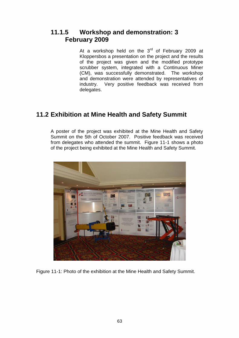
A poster of the project was exhibited at the Mine Health and Safety Summit on the 5th of October 2007. Positive feedback was received from delegates who attended the summit. Figure 11-1 shows a photo of the project being exhibited at the Mine Health and Safety Summit.
Figure 11-1: Photo of the exhibition at the Mine Health and Safety Summit.
64
11.3 Presentation at Mine ventilation Society
On 11 May 2007 a presentation about the results of the project was given at a conference of the Mine Ventilation Society.
65
12 CONCLUSIONS
An alternative to onboard continuous miner scrubbers and force in-heading fan ventilation system was developed. The system developed consists of the following sub-systems:
o Ventilation system (take positive control of airflow): The fan of the scrubber is connected to ducting which channels the air out of the boxcut and a jet fan positioned at the entrance of the boxcut forces fresh air into the boxcut.
o A new scrubber making use of a rotating cloth, which is continuously cleaned by a water spray system.
o Use of surfactants. The system and sub-systems were extensively tested at the Kloppersbos test facility of the CSIR. A Continuous Miner (CM) was taken to Kloppersbos to be able to evaluate the system on a real CM. The system was successfully evaluated and demonstrated to industry. Increased effectiveness of in-heading ventilation with lower flammable gas and airborne dust concentrations was demonstrated and the noise levels were slightly lower. Making use of this system in coalmines would have the following impact:
o Reduced risk of airborne particles and thereby reducing pneumoconiosis.
o Reduced risk of coal dust explosions caused by airborne particles. o Reduced risk of methane explosions.
The use of surfactants, with resultant lower dust levels, was successfully tested underground at Sasol Mining. A lot of work was done for the underground evaluation of the scrubber, including the design and building of a new scrubber specifically for these tests. However, several problems were encountered, which prevented these tests from taking place. Due to the problems encountered it was decided by the MHSC that the project should be concluded without the underground evaluations of the prototype scrubber and ventilation systems. The underground evaluations will be done in conjunction with Sasol Mining at a later stage. Technology transfer through a number of demonstrations and workshops, which were attended by representatives of industry, MHSC and labour. Industry and the MHSC were involved with the scoping of the project, evaluations of the prototypes as well as suggesting certain additional work to the project. A poster of the project was exhibited at the Mine Health and Safety Summit and a presentation about the project was given at a conference of the Mine Ventilation Society.
66
13 REFERENCES
Du Plessis, J.J.L., Belle, B.K., Vassard, P.S., January 1999, Mechanical miner environmental control: Evaluation and dust control systems in a ventilation simulation tunnel, Safety in Mines Research Advisory Committee, COL 518.
Eksteen, J.J.A, April 2008, Noise measurement and control on axial fans and scrubbers. Safety in Mines Research Advisory Committee, SIM 050501 Track B2.1.
67
APPENDIX A:
PROJECT SCOPE AND APPROPRIATE METHODOLOGY FOR THE DEVELOPMENT,
EVALUATION AND TESTING OF AN ALTERNATIVE TO ONBOARD CONTINUOUS
MINER SCRUBBERS AND FORCE FAN IN-HEADING VENTILATION SYSTEMS FOR
CONTINUOUS MINER HEADINGS IN SOUTH AFRICAN COALMINES
68
1. Problem definition and summary of literature survey.
See figure 1 attached.
2. Measuring of operational parameters in mining process:
The idea of this phase of the project is to get a better understanding of
the absolute conditions underground as this will have a big influence on
the final outcome of the project. It is essential to fully understand the
prevailing conditions before any attempts on improvement can be
suggested.
The following operational parameters, as shown in figure 1, will have to
be measured i.e.
Flow of air in and around the scrubber
Flow of air in and out of boxcut/complete tunnel
Verify the flow rate of the jet fans
Sound pressure levels around CM and jet fans
Structural vibration levels on fans
Dust levels
Water flow rate
Try to measure methane gas levels
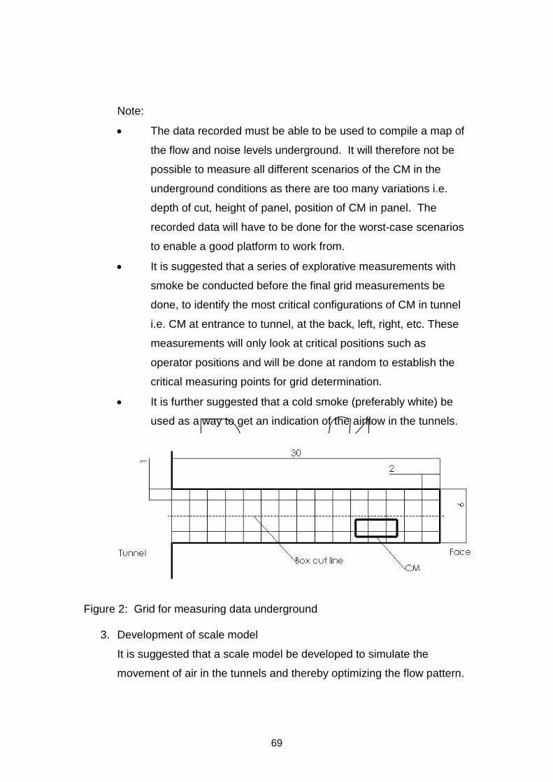
It is suggested that a grid is compiled that will enable the recording of
sound and airflow data in the boxcut and around the CM. See figure 2.
It is suggested that two sets of readings be taken to accommodate the
height of the seam i.e. 1.5 m and 3 m. (Typically 30 readings for the
boxcut will have to be taken and 60 readings for the full cut)
In the boxcut (Half of the tunnel is being cut)
Full cut: (?) taking the rest of the tunnel with the resultant
disturbed flow (Interaction between air circulation in the first cut
(due to the jet fan) and the locally generated recirculation of air
caused by the operation of scrubber units and the continuous
miner) around the CM.
69
Note:
The data recorded must be able to be used to compile a map of
the flow and noise levels underground. It will therefore not be
possible to measure all different scenarios of the CM in the
underground conditions as there are too many variations i.e.
depth of cut, height of panel, position of CM in panel. The
recorded data will have to be done for the worst-case scenarios
to enable a good platform to work from.
It is suggested that a series of explorative measurements with
smoke be conducted before the final grid measurements be
done, to identify the most critical configurations of CM in tunnel
i.e. CM at entrance to tunnel, at the back, left, right, etc. These
measurements will only look at critical positions such as
operator positions and will be done at random to establish the
critical measuring points for grid determination.
It is further suggested that a cold smoke (preferably white) be
used as a way to get an indication of the airflow in the tunnels.
Figure 2: Grid for measuring data underground
3. Development of scale model
It is suggested that a scale model be developed to simulate the
movement of air in the tunnels and thereby optimizing the flow pattern.
70
Suggestion:
In the SASOL training centre there is a model of the tunnels with
a Perspex roof. It is suggested that it is investigated to see if
this facility can be used to do this type of simulation. If this is
not possible maybe a scale model of one tunnel equipped with
all the auxiliary equipment can be built.
Another option is to use the transparent multi-entry Board and
pillar model at Kloppersbos
The scale model can then also be used as verification for any possible
CFD work that might be needed to solve the flow problem in the
tunnels.
4. Development of concepts
The following concepts have already been established and it will have
to be investigated further to establish the possible success of each.
Solid particle separator – similar to the equipment sold by
Donaldson
Water curtain – The work done by SASOL will have to be
evaluated
Wethead – The work done by Anglo will have to evaluated
Additional fans to ensure continuous dilution of the methane gas
Surfactants.
Each of the mentioned concepts will have to be tested and evaluated to
analyse the possible rate for success.
5. Full scale testing
One or a combination of the chosen concepts will have to undergo full
scale testing at the Kloppersbos test facility. The purpose of these
tests will be to verify the designs. The parameters that will have to be
tested and evaluated:
71
Respirable dust levels – it will have to be proven that the dust
levels can be brought down below 2 mg/m3
It will have to be proven that the low dust levels can be
sustained for a minimum period of 8 hours minimum
maintenance intervals.
Noise levels – the prevailing system noise level will have to be
below 85 dBA as the CM operator and shuttle car driver is
subjected to this noise level 8 hours/day
Control of methane levels
6. Implementation into test tunnels
The final design or combinations of design will have to be tested in
underground operational conditions.
The parameters that will have to be tested and evaluated underground
are:
o Respirable dust levels – it will have to be proven that the dust
levels can be brought below 2 mg/m3
o It will have to be proven that the low dust levels can be
sustained for a minimum period of 8 hours -minimum
maintenance intervals.
o Noise levels – the prevailing system noise level will have to be
below 85 dBA as the CM operator and shuttle car driver is
subjected to this noise level 8 hours/day. It was decided that the
noise levels are to be addressed in project: SIM050501 Track
B2.1, Noise Measurement and Control on Axial fans and
Scrubbers.
o Control of flammable gas concentration below 1.4%
72
Figure 1: General information regarding CM miners

73
APPENDIX B:
COMPUTATIONAL FLUID DYNAMIC (CFD) EVALUATIONS OF ALTERNATIVE VENTILATION
SYSTEMS
74
APPENDIX C:
MANUFACTURING DRAWINGS OF PROTOTYPE SCRUBBER

75