Embed Size (px)
Citation preview
Hornsby Shire Council
ABN 20 706 996 972 PO Box 37, Hornsby NSW 1630 Phone 02 9847 6666 Email [email protected]
296 Peats Ferry Rd, Hornsby 2077 Fax 02 9847 6999 Web hornsby.nsw.gov.au
DEVELOPMENT DESIGN SPECIFICATION 0010
QUALITY REQUIREMENTS FOR DESIGN
© AUS-SPEC (Oct 11) July 2016
0010 Quality Requirements for Design
Hornsby Shire Council
ABN 20 706 996 972 PO Box 37, Hornsby NSW 1630 Phone 02 9847 6666 Email [email protected]
296 Peats Ferry Rd, Hornsby 2077 Fax 02 9847 6999 Web hornsby.nsw.gov.au
SPECIFICATION 0010 – QUALITY REQUIREMENTS FOR DESIGN
CLAUSE CONTENTS PAGE
GENERAL ............................................................................................................................................................ 1
1.1 RESPONSIBILITIES ............................................................................................................................. 1
1.2 CROSS RERERENCES ....................................................................................................................... 1
1.3 REFERENCED DOCUMENTS ............................................................................................................. 1
1.4 STANDARDS ........................................................................................................................................ 2
1.5 INTERPRETATIONS ............................................................................................................................ 2
QUALITY MANAGEMENT SYSTEM FOR DESIGN ........................................................................................... 2
2.1 GENERAL REQUIREMENTS ............................................................................................................... 2
2.2 DESIGN PLANNING ............................................................................................................................. 2
2.3 DESIGN INPUT AND OUTPUT ............................................................................................................ 3
2.4 REVIEW, VERIFICATION AND VALIDATION ...................................................................................... 3
2.5 CONTROL OF DESIGN CHANGES ..................................................................................................... 4
2.6 CONTROL OF DOCUMENTATION ...................................................................................................... 4
2.7 CONTROL OF RECORDS .................................................................................................................... 5
2.8 CONTROL OF NON-CONFORMANCE ................................................................................................ 5
ANNEXURE A ...................................................................................................................................................... 6
ANNEXURE B .................................................................................................................................................... 19
ANNEXURE C .................................................................................................................................................... 22
0010 Quality requirements for design
© AUS-SPEC (Oct 11) 1 HORNSBY SHIRE COUNCIL
0010 QUALITY REQUIREMENTS FOR DESIGN
1 GENERAL
1.1 RESPONSIBILITIES
Objective General: Provide a Quality Management System (QMS) for the execution and recording of design processes.
Performance Requirements:
- Demonstrate the QMS by providing records of the design process.
- Provide documentation relevant to asset management.
Designer’s qualifications An Engineer suitably experienced and qualified so as to be accepted as a member of the Institution of Engineers, Australia shall be accepted as qualified to prepare plans for roadworks, drainage works, water supply, sewerage works including pumping stations, canal works including flood control structures, bridges, retaining walls, buildings and miscellaneous structures.
A suitably qualified Registered Surveyor shall be accepted as qualified to prepare plans only for roadworks geometric design and minor drainage works excluding flood control structures.
1.2 CROSS REFERENCES
General Conform to the following Work Sections:
0021 Site regrading
0041 Geometric road layout
0042 Pavement design
0043 Subsurface drainage (Design)
0044 Pathway and cycleways
0061 Bridges and related structure
0075 Control of erosion and sedimentation (Design)
1.3 REFERENCED DOCUMENTS
The following documents are incorporated into this worksection by reference:
Standards AS/NZS 1170-Various Structural design actions AS 1684-Various Residential timber-framed construction AS 1742 Manual of uniform traffic control devices AS 1742.2-2009 Traffic control devices for general use AS 3600-2009 Concrete structures AS 4100-1998 Steel structures AS 5100-Various Bridge design AS/NZS ISO-9000:2006 Quality management systems - Fundamentals and vocabulary AS/NZS ISO-9001:2008 Quality management systems - Requirements AS ISO-10013:2003 Guidelines for quality management system documentation AS/NZS ISO-19011:2003 Guidelines for quality and/or environments management systems auditing SAA HB 90.3-2000 The Construction Industry - Guide to ISO 9001:2000
Other publications
Section 90 (EP&A ACT) Local Government Act (1919) Subdivisions Pt XII Local Government Act (1993) Interim Policies and Guidelines
NSW Department of Public Works and Services Guidelines for reticulation and sewerage systems
Engineers Australia
0010 Quality requirements for design
© AUS-SPEC (Oct 11) 2 HORNSBY SHIRE COUNCIL
Australian Rainfall and Runoff (AR&R) – 1997
WSAA WSA 02: 2002 Sewerage Code of Australia WSA 02 WSA 03: 2011 Water Reticulation Code of Australia Version 3.1
1.4 STANDARDS
General Standard: To AS/NZS ISO 9001.
1.5 INTERPRETATIONS
Abbreviations General: For the purposes of this worksection the following abbreviations apply:
- BCA: Building Code of Australia.
- QMP: Quality Management Plan.
- QMS: Quality Management System.
Definitions General: For the purposes of this worksection the definitions given in AS/NZS ISO 9000 and the following apply:
- Accreditation: Certification by a statutory or approved authority of the facilities, capabilities, objectivity, competence and integrity of an organisation or individual to provide a specified service and/or required operation.
- Certification: Assertion, in writing, of facts.
- Hold point: A defined position in the different stages of the Contract beyond which work can not proceed without mandatory verification and acceptance by the Superintendent.
- Non-conformance: Non fulfilment of a requirement, need or expectation that is stated, generally implied or obligatory.
- Professional engineer: A person who is listed on the National Professional Engineers Register (NPER) and has appropriate experience and competence in the relevant discipline at the relevant time.
- Quality design check lists: Forms completed during the design process verifying key steps, and records.
- Records: Documents and data which are no longer subject to alteration and provide evidence of activities performed.
- Witness point: A nominated position in the different stages of the Contract where the option of attendance may be exercised by the Superintendent, after notification of the requirement.
2 QUALITY MANAGEMENT SYSTEM FOR DESIGN
2.1 GENERAL REQUIREMENTS
Design organisation’s quality plan Requirements: Provide a Quality Plan in conformance with AS/NZS ISO 9001, to include the following:
- Quality manual including the organisation’s Quality Policy.
- Responsibilities for the implementation of the Quality Policy for the project.
- A commitment from top management to the development and implementation of the QMS.
- Evidence of the resources, infrastructure and work environment for the project.
- Policy for evaluating and selecting Subconsultants.
2.2 DESIGN PLANNING
General Collaboration: Coordinate the different groups involved in the development of the design to ensure effective communication and clear assignment of responsibility.
Integrated planning with Subconsultants: Verify and incorporate inputs into the design process.
Design quality plan Requirement: Provide a design Quality Plan, to include the following:
- Design stages.
- Review, verification and validation for each stage (Design program and procedures).
0010 Quality requirements for design
© AUS-SPEC (Oct 11) 3 HORNSBY SHIRE COUNCIL
- Responsibilities and authorities for design.
- Define the design team, including Subconsultants, names of team members, roles and technical interfaces.
- Details of the resources assigned to the project.
- Organisation chart including communication paths with the Superintendent, the Principal, other Consultants and Contractors.
- For the construction phase, reference the Contractor’s program for review and verification such as site inspections.
- Design inputs such as requirements and acceptable criteria.
- Any Witness Points or Hold Points for the design.
- Programmed approvals/consultations with regulatory authorities.
- Any third party review/verification/validation required by the Principal or regulating authority.
- Proposed design documentation.
- Procedure for managing design changes of project audits.
- Sign off of activities and record using the checklists in the Annexures.
2.3 DESIGN INPUT AND OUTPUT
Design input Input to AS/NZS ISO 9001 clause 7.3.2: Identify, document and review for adequacy the following:
- Principal’s brief
- Site information
- Codes of practice
- Regulatory and statutory requirements
- Performance criteria
- Design criteria
- Materials
- Requirement: Give notice if the design inputs do not provide sufficient information for verification.
- Review: Submit design proposals for approval by the Principal at appropriate stages.
Design output Output to AS/NZS ISO 9001 clause 7.3.3: To include the following, produced at various stages:
- Advice.
- Calculations.
- Drawings.
- Models.
- Other contract documents.
- Reports.
- Schedules of quantities.
- Sketches for shop drawings.
- Specifications.
Design checklist: Provide a quality record of the design processes and integrate additional criteria, as required, in the design checklists in Annexure A.
Acceptance criteria: Define on drawings or in the specification the acceptance criteria for standards of workmanship and other design requirements.
Define: Key characteristics e.g. safety signs.
2.4 REVIEW, VERIFICATION AND VALIDATION
Design review Design meetings: Minute design meetings with all relevant parties in attendance and make sure the following considerations are included in the agenda:
- Principal’s requirements.
- Sequence of design activities.
- Conformance with the design brief.
- Identification and control of design interfaces.
0010 Quality requirements for design
© AUS-SPEC (Oct 11) 4 HORNSBY SHIRE COUNCIL
- Construction processes.
- Safety methods.
- Methods of verification.
- Consultation including Council or authority approvals, public input and existing utilities.
Method of quality recording: Provide and maintain quality records by notation on documents, minutes and checklists signed off by the review leader.
Design verification Verification: At the end of each design stage examine the result of a given activity for conformance with the specified input requirements for that activity, include the following:
- Document the process.
- Identify responsibilities.
- Maintain adequate records of the verification.
- Site investigation and reporting.
Design validation Validation: Following completion of design, validation shall be performed to make sure the design has met the specified requirements, include the following:
- Document the process.
- Identify responsibilities.
- Maintain adequate records of the validation.
Audit Notice: Provide all reasonable assistance for the inspection of records of designs submitted to Council for acceptance. Provide access to the designer’s premises on a 24 hour notice basis.
2.5 CONTROL OF DESIGN CHANGES
Design changes Requirement: Review and amend the design quality plan as necessary during the course of the design, include the following:
- Manage, identify, record any design changes.
- Identify who can make and approve changes.
- Procedure for review of wider implications of design changes.
Process for changing documents after issue for construction: Once documents are issued for construction, any changes must go through the review, verification and approval process prior to re-release for construction.
Record: Maintain a register of design changes.
2.6 CONTROL OF DOCUMENTATION
Documentation Distribution control: Maintain a master list of controlled documents, to include the following information:
- The source of data used in calculations and on drawings.
- Record of the personnel authorised to review, approve and change documents.
Design documentation and data: Provide calculations, sketches, drawings (including those retained for reference or circulated outside the design team), data sheets and specifications.
Requirement: Control and retain documents and data relating to the project e.g. from the Principal, other Consultants or Subconsultants and suppliers.
Design change register: Record changes made to any documents after they have been issued for construction.
Certification Certification Report: Submit for approval a Certification Report signed by the designer accompanied by drawings and specifications. Conform with the design certificate and checklists included in Annexure A.
Certification of preliminary drawings: Submit a Certification Report with all preliminary drawings. Submit an updated Certification Report with the submission of final drawings. A Certification Report is not required when submitting sketch plans or concept plans.
Drawing requirements Drawings: Define and set out the design concepts on design drawings in conformance with the following:
0010 Quality requirements for design
© AUS-SPEC (Oct 11) 5 HORNSBY SHIRE COUNCIL
- Prepare all design drawings on a Council approved standard sheet and clearly number with each sheet numbered as part of a set. Annexure B provides guidelines for grouping information in design drawings.
- Refer to design worksections for documentation requirements.
- Provide a space in the bottom right hand corner of each drawing for an assigned number provided by Council.
- Do not overcrowd the drawings with information.
- Do not use colour to distinguish information.
- If A1 or A2 size sheets are used, the drawings must be clear enough to be reduced to A3 paper size without loss of clarity.
Survey Requirements
The requirements for surveying for the purposes of the design shall be in accordance with Annexure C.
2.7 CONTROL OF RECORDS
Records Requirement: Retain appropriate design records in a format which can be understood readily with no prior knowledge of the particular design.
Copies of records: Make copies of records available to Council upon request without charge.
Design file: Maintain a design file containing records of calculations, approvals and decisions, geotechnical data and other design data that could be relevant in reviewing aspects of the design or planning future maintenance responsibilities.
Calculation record retention: Keep all calculations for the duration of the construction maintenance period.
Hydrologic and hydraulic design records: To 0074 Stormwater drainage (Design).
2.8 CONTROL OF NON-CONFORMANCE
Design variations Record: Identify on the Certification Report checklists any aspects of the design which do not meet the requirements or tolerances set out in this worksection and other applicable Council design and construction specifications.
0010 Quality requirements for design
© AUS-SPEC (Oct 11) 6 HORNSBY SHIRE COUNCIL
3 ANNEXURE A
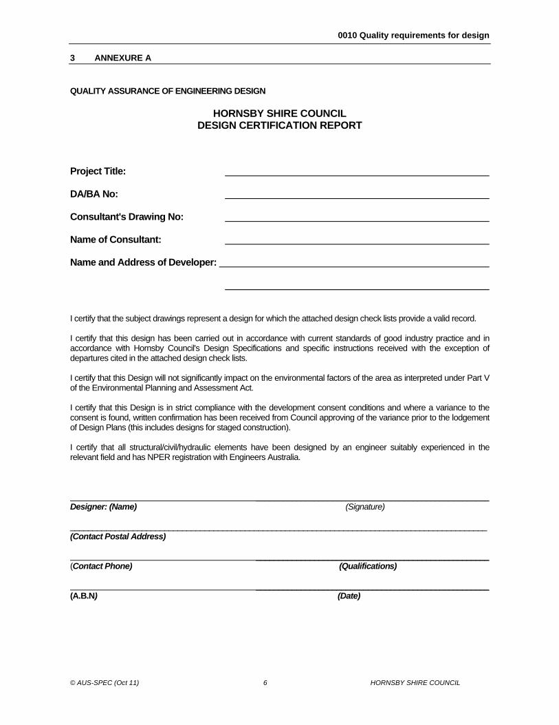
QUALITY ASSURANCE OF ENGINEERING DESIGN HORNSBY SHIRE COUNCIL DESIGN CERTIFICATION REPORT Project Title: DA/BA No: Consultant's Drawing No: Name of Consultant: Name and Address of Developer: I certify that the subject drawings represent a design for which the attached design check lists provide a valid record. I certify that this design has been carried out in accordance with current standards of good industry practice and in accordance with Hornsby Council's Design Specifications and specific instructions received with the exception of departures cited in the attached design check lists. I certify that this Design will not significantly impact on the environmental factors of the area as interpreted under Part V of the Environmental Planning and Assessment Act. I certify that this Design is in strict compliance with the development consent conditions and where a variance to the consent is found, written confirmation has been received from Council approving of the variance prior to the lodgement of Design Plans (this includes designs for staged construction). I certify that all structural/civil/hydraulic elements have been designed by an engineer suitably experienced in the relevant field and has NPER registration with Engineers Australia. ____________________________________________________ Designer: (Name) (Signature) _____________________________________________________________________________________________ (Contact Postal Address) ____________________________________________________ (Contact Phone) (Qualifications) ____________________________________________________ (A.B.N) (Date)
0010 Quality requirements for design
© AUS-SPEC (Oct 11) 7 HORNSBY SHIRE COUNCIL
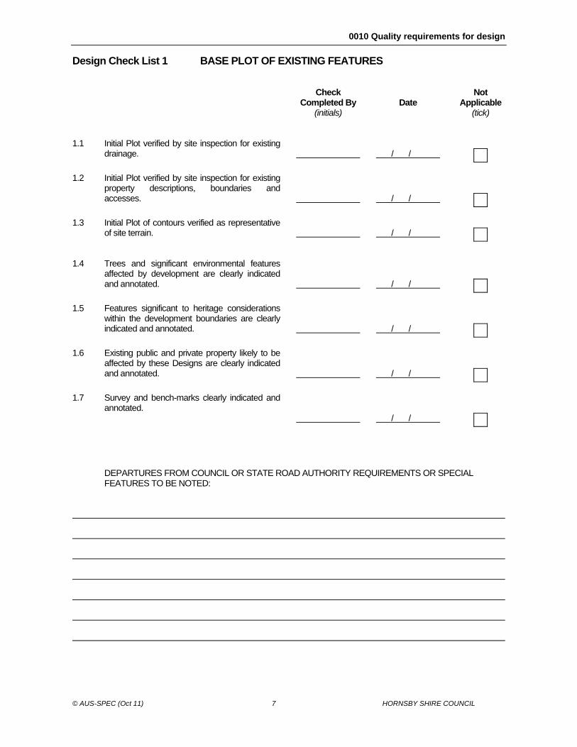
Design Check List 1 BASE PLOT OF EXISTING FEATURES Check
Completed By (initials)
Date
Not Applicable (tick)
1.1 Initial Plot verified by site inspection for existing
drainage.
/ /
1.2 Initial Plot verified by site inspection for existing
property descriptions, boundaries and accesses.
/ /
1.3 Initial Plot of contours verified as representative
of site terrain.
/ /
1.4 Trees and significant environmental features
affected by development are clearly indicated and annotated.
/ /
1.5 Features significant to heritage considerations
within the development boundaries are clearly indicated and annotated.
/ /
1.6 Existing public and private property likely to be
affected by these Designs are clearly indicated and annotated.
/ /
1.7 Survey and bench-marks clearly indicated and
annotated.
/ /
DEPARTURES FROM COUNCIL OR STATE ROAD AUTHORITY REQUIREMENTS OR SPECIAL
FEATURES TO BE NOTED:
0010 Quality requirements for design
© AUS-SPEC (Oct 11) 8 HORNSBY SHIRE COUNCIL
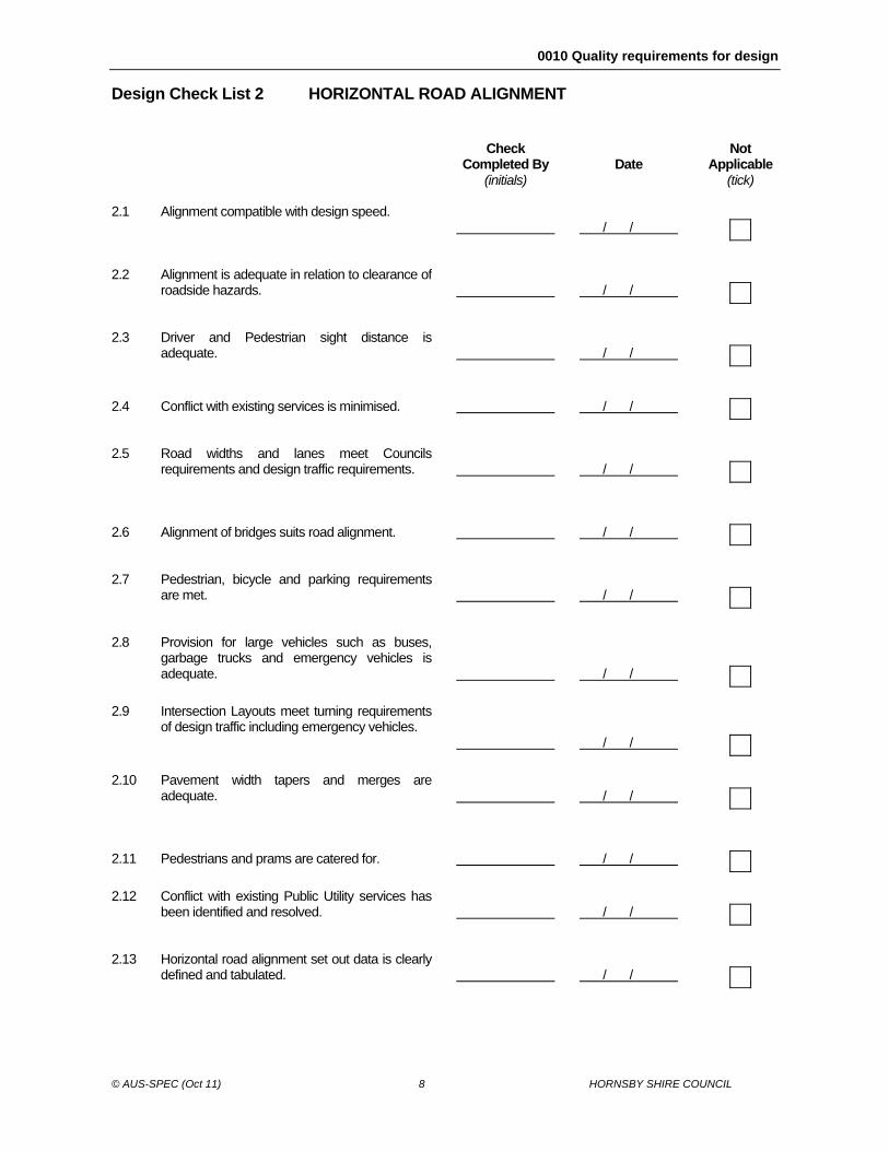
Design Check List 2 HORIZONTAL ROAD ALIGNMENT Check
Completed By (initials)
Date
Not Applicable (tick)
2.1 Alignment compatible with design speed.
/ /
2.2 Alignment is adequate in relation to clearance of
roadside hazards.
/ /
2.3 Driver and Pedestrian sight distance is
adequate.
/ /
2.4 Conflict with existing services is minimised.
/ /
2.5 Road widths and lanes meet Councils
requirements and design traffic requirements.
/ /
2.6 Alignment of bridges suits road alignment.
/ /
2.7 Pedestrian, bicycle and parking requirements
are met.
/ /
2.8 Provision for large vehicles such as buses,
garbage trucks and emergency vehicles is adequate.
/ /
2.9 Intersection Layouts meet turning requirements
of design traffic including emergency vehicles.
/ /
2.10 Pavement width tapers and merges are
adequate.
/ /
2.11 Pedestrians and prams are catered for.
/ /
2.12 Conflict with existing Public Utility services has
been identified and resolved.
/ /
2.13 Horizontal road alignment set out data is clearly
defined and tabulated.
/ /

0010 Quality requirements for design
© AUS-SPEC (Oct 11) 9 HORNSBY SHIRE COUNCIL
DEPARTURES FROM COUNCIL OR STATE ROAD AUTHORITY REQUIREMENTS OR SPECIAL
FEATURES TO BE NOTED:
0010 Quality requirements for design
© AUS-SPEC (Oct 11) 10 HORNSBY SHIRE COUNCIL
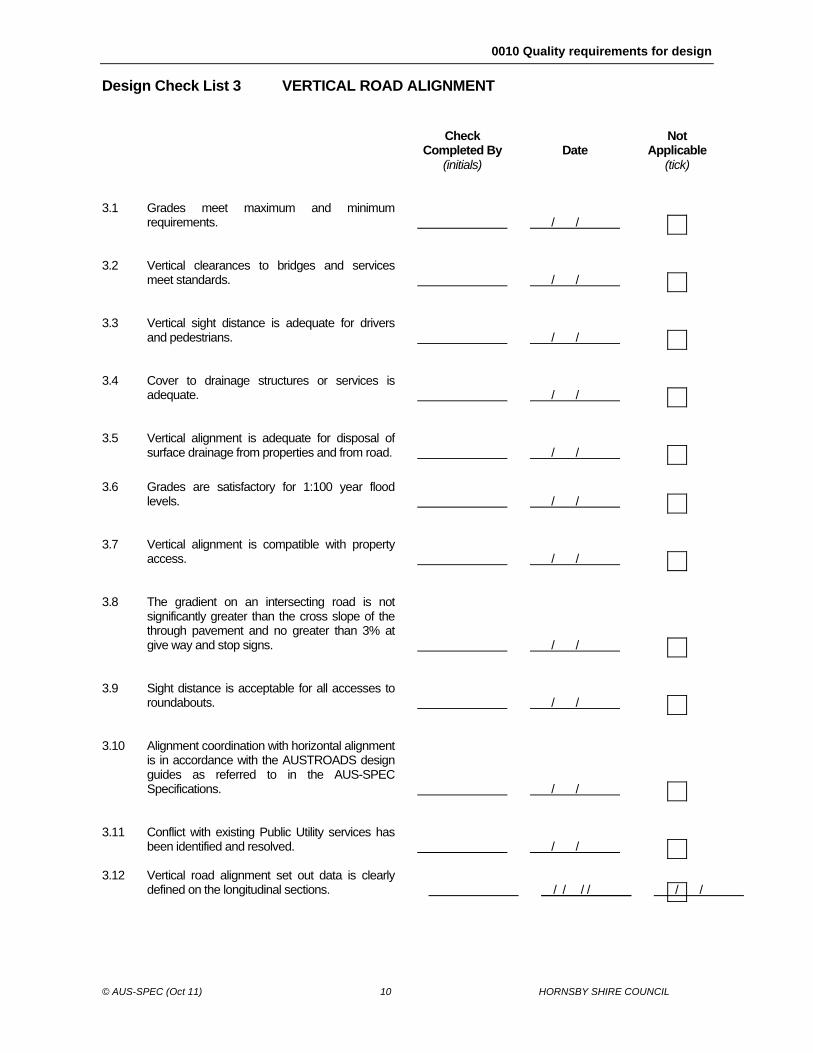
Design Check List 3 VERTICAL ROAD ALIGNMENT Check
Completed By (initials)
Date
Not Applicable (tick)
3.1 Grades meet maximum and minimum
requirements.
/ /
3.2 Vertical clearances to bridges and services
meet standards.
/ /
3.3 Vertical sight distance is adequate for drivers
and pedestrians.
/ /
3.4 Cover to drainage structures or services is
adequate.
/ /
3.5 Vertical alignment is adequate for disposal of
surface drainage from properties and from road.
/ /
3.6 Grades are satisfactory for 1:100 year flood
levels.
/ /
3.7 Vertical alignment is compatible with property
access.
/ /
3.8 The gradient on an intersecting road is not
significantly greater than the cross slope of the through pavement and no greater than 3% at give way and stop signs.
/ /
3.9 Sight distance is acceptable for all accesses to
roundabouts.
/ /
3.10 Alignment coordination with horizontal alignment
is in accordance with the AUSTROADS design guides as referred to in the AUS-SPEC Specifications.
/ /
3.11 Conflict with existing Public Utility services has
been identified and resolved.
/ /
3.12 Vertical road alignment set out data is clearly defined on the longitudinal sections.
/ /
/ /
/ /
0010 Quality requirements for design
© AUS-SPEC (Oct 11) 11 HORNSBY SHIRE COUNCIL
DEPARTURES FROM COUNCIL OR STATE ROAD AUTHORITY REQUIREMENTS OR SPECIAL
FEATURES TO BE NOTED:
0010 Quality requirements for design
© AUS-SPEC (Oct 11) 12 HORNSBY SHIRE COUNCIL
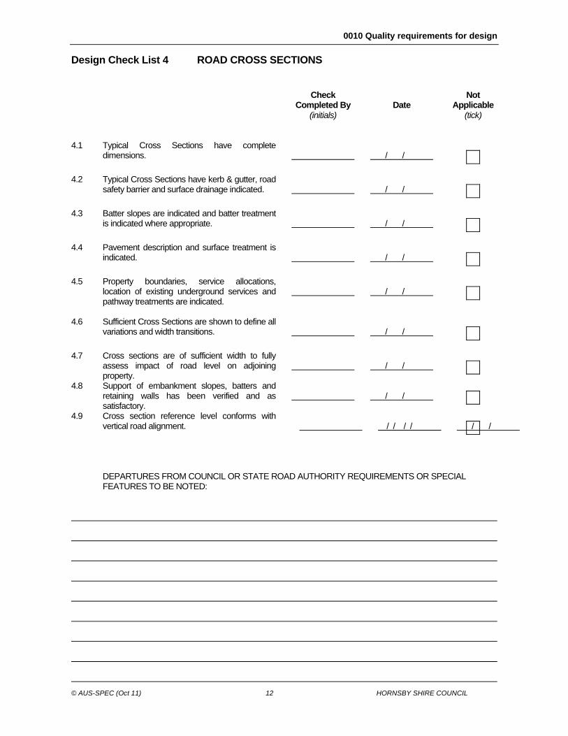
Design Check List 4 ROAD CROSS SECTIONS Check
Completed By (initials)
Date
Not Applicable (tick)
4.1 Typical Cross Sections have complete
dimensions.
/ /
4.2 Typical Cross Sections have kerb & gutter, road
safety barrier and surface drainage indicated.
/ /
4.3 Batter slopes are indicated and batter treatment
is indicated where appropriate.
/ /
4.4 Pavement description and surface treatment is
indicated.
/ /
4.5 Property boundaries, service allocations,
location of existing underground services and pathway treatments are indicated.
/ /
4.6 Sufficient Cross Sections are shown to define all
variations and width transitions.
/ /
4.7 Cross sections are of sufficient width to fully
assess impact of road level on adjoining property.
/ /
4.8 Support of embankment slopes, batters and retaining walls has been verified and as satisfactory.
/ /
4.9 Cross section reference level conforms with vertical road alignment.
/ /
/ /
/ /
DEPARTURES FROM COUNCIL OR STATE ROAD AUTHORITY REQUIREMENTS OR SPECIAL
FEATURES TO BE NOTED:
0010 Quality requirements for design
© AUS-SPEC (Oct 11) 13 HORNSBY SHIRE COUNCIL
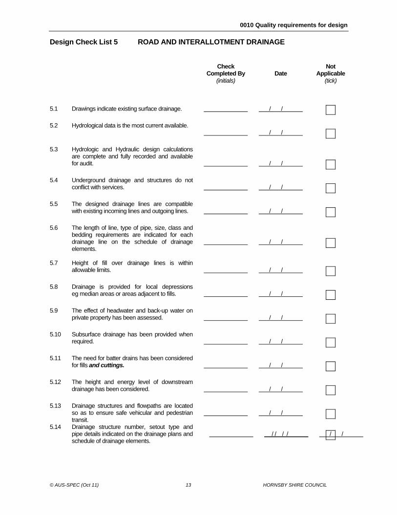
Design Check List 5 ROAD AND INTERALLOTMENT DRAINAGE Check
Completed By (initials)
Date
Not Applicable (tick)
5.1 Drawings indicate existing surface drainage.
/ /
5.2 Hydrological data is the most current available.
/ /
5.3 Hydrologic and Hydraulic design calculations
are complete and fully recorded and available for audit.
/ /
5.4 Underground drainage and structures do not
conflict with services.
/ /
5.5 The designed drainage lines are compatible
with existing incoming lines and outgoing lines.
/ /
5.6 The length of line, type of pipe, size, class and
bedding requirements are indicated for each drainage line on the schedule of drainage elements.
/ /
5.7 Height of fill over drainage lines is within
allowable limits.
/ /
5.8 Drainage is provided for local depressions
eg median areas or areas adjacent to fills.
/ /
5.9 The effect of headwater and back-up water on
private property has been assessed.
/ /
5.10 Subsurface drainage has been provided when
required.
/ /
5.11 The need for batter drains has been considered
for fills and cuttings.
/ /
5.12 The height and energy level of downstream
drainage has been considered.
/ /
5.13 Drainage structures and flowpaths are located
so as to ensure safe vehicular and pedestrian transit.
/ /
5.14 Drainage structure number, setout type and pipe details indicated on the drainage plans and schedule of drainage elements.
/ /
/ /
/ /
0010 Quality requirements for design
© AUS-SPEC (Oct 11) 14 HORNSBY SHIRE COUNCIL
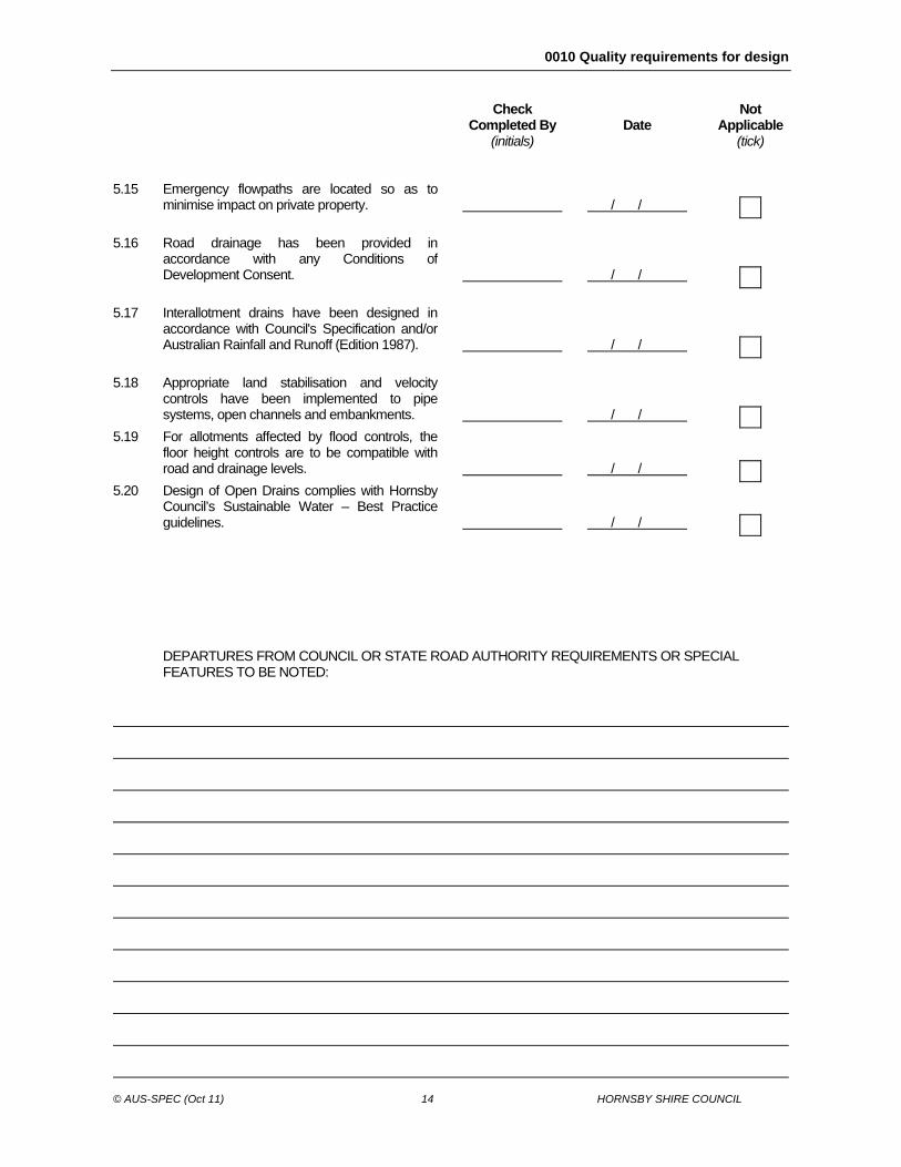
Check
Completed By (initials)
Date
Not Applicable (tick)
5.15 Emergency flowpaths are located so as to
minimise impact on private property.
/ /
5.16 Road drainage has been provided in
accordance with any Conditions of Development Consent.
/ /
5.17 Interallotment drains have been designed in
accordance with Council's Specification and/or Australian Rainfall and Runoff (Edition 1987).
/ /
5.18 Appropriate land stabilisation and velocity
controls have been implemented to pipe systems, open channels and embankments.
/ /
5.19 For allotments affected by flood controls, the
floor height controls are to be compatible with road and drainage levels.
/ /
5.20 Design of Open Drains complies with Hornsby
Council’s Sustainable Water – Best Practice guidelines.
/ /
DEPARTURES FROM COUNCIL OR STATE ROAD AUTHORITY REQUIREMENTS OR SPECIAL
FEATURES TO BE NOTED:
0010 Quality requirements for design
© AUS-SPEC (Oct 11) 15 HORNSBY SHIRE COUNCIL
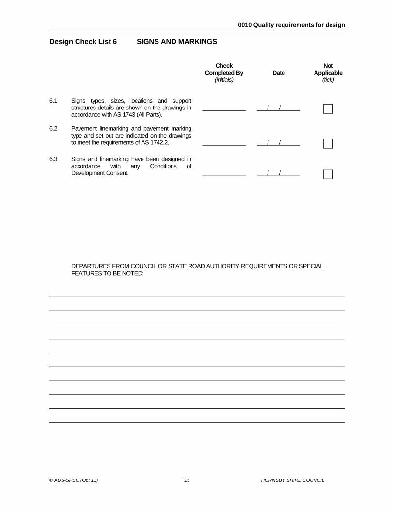
Design Check List 6 SIGNS AND MARKINGS Check
Completed By (initials)
Date
Not Applicable (tick)
6.1 Signs types, sizes, locations and support
structures details are shown on the drawings in accordance with AS 1743 (All Parts).
/ /
6.2 Pavement linemarking and pavement marking
type and set out are indicated on the drawings to meet the requirements of AS 1742.2.
/ /
6.3 Signs and linemarking have been designed in
accordance with any Conditions of Development Consent.
/ /
DEPARTURES FROM COUNCIL OR STATE ROAD AUTHORITY REQUIREMENTS OR SPECIAL
FEATURES TO BE NOTED:
0010 Quality requirements for design
© AUS-SPEC (Oct 11) 16 HORNSBY SHIRE COUNCIL
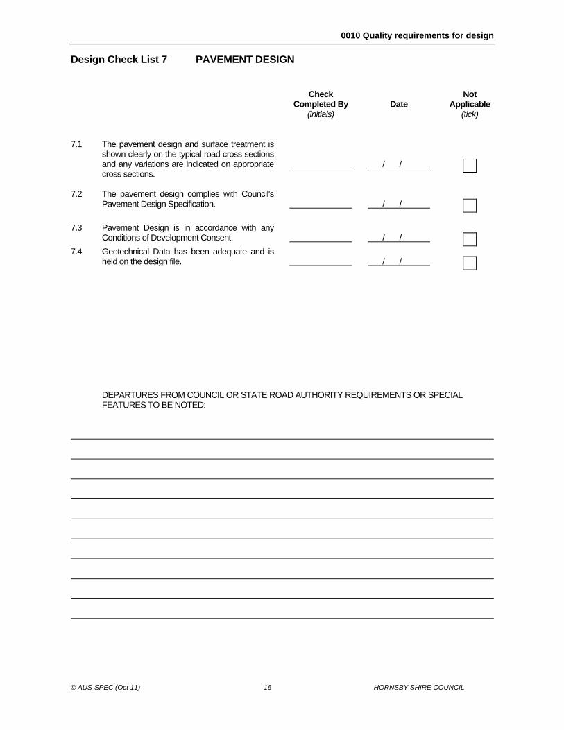
Design Check List 7 PAVEMENT DESIGN Check
Completed By (initials)
Date
Not Applicable (tick)
7.1 The pavement design and surface treatment is
shown clearly on the typical road cross sections and any variations are indicated on appropriate cross sections.
/ /
7.2 The pavement design complies with Council's
Pavement Design Specification.
/ /
7.3 Pavement Design is in accordance with any
Conditions of Development Consent.
/ /
7.4 Geotechnical Data has been adequate and is
held on the design file.
/ /
DEPARTURES FROM COUNCIL OR STATE ROAD AUTHORITY REQUIREMENTS OR SPECIAL
FEATURES TO BE NOTED:
0010 Quality requirements for design
© AUS-SPEC (Oct 11) 17 HORNSBY SHIRE COUNCIL
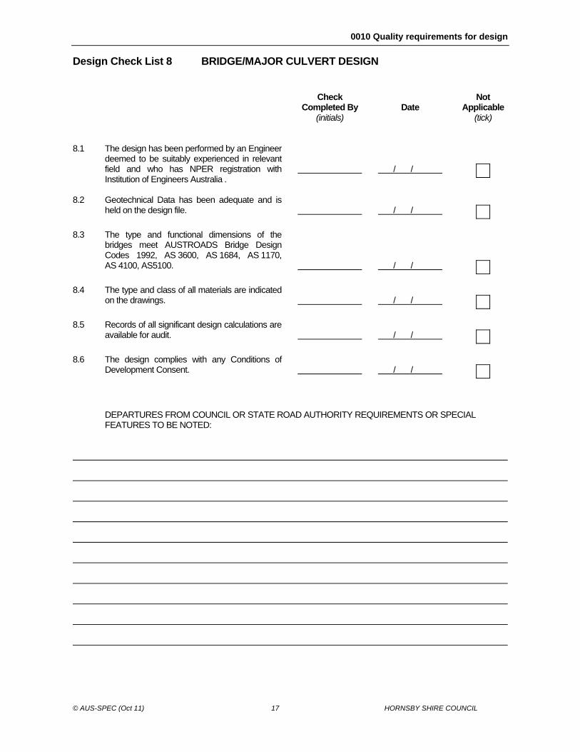
Design Check List 8 BRIDGE/MAJOR CULVERT DESIGN Check
Completed By (initials)
Date
Not Applicable (tick)
8.1 The design has been performed by an Engineer
deemed to be suitably experienced in relevant field and who has NPER registration with Institution of Engineers Australia .
/ /
8.2 Geotechnical Data has been adequate and is
held on the design file.
/ /
8.3 The type and functional dimensions of the
bridges meet AUSTROADS Bridge Design Codes 1992, AS 3600, AS 1684, AS 1170, AS 4100, AS5100.
/ /
8.4 The type and class of all materials are indicated
on the drawings.
/ /
8.5 Records of all significant design calculations are
available for audit.
/ /
8.6 The design complies with any Conditions of
Development Consent.
/ /
DEPARTURES FROM COUNCIL OR STATE ROAD AUTHORITY REQUIREMENTS OR SPECIAL
FEATURES TO BE NOTED:
0010 Quality requirements for design
© AUS-SPEC (Oct 11) 18 HORNSBY SHIRE COUNCIL
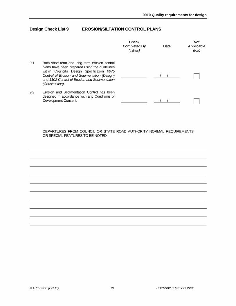
Design Check List 9 EROSION/SILTATION CONTROL PLANS Check
Completed By (initials)
Date
Not Applicable (tick)
9.1 Both short term and long term erosion control
plans have been prepared using the guidelines within Council's Design Specification 0075 Control of Erosion and Sedimentation (Design) and 1102 Control of Erosion and Sedimentation (Construction).
/ /
9.2 Erosion and Sedimentation Control has been
designed in accordance with any Conditions of Development Consent.
/ /
DEPARTURES FROM COUNCIL OR STATE ROAD AUTHORITY NORMAL REQUIREMENTS
OR SPECIAL FEATURES TO BE NOTED:
0010 Quality requirements for design
© AUS-SPEC (Oct 11) 19 HORNSBY SHIRE COUNCIL
4 ANNEXURE B
MINIMUM DRAFTING GUIDELINES 1. DOCUMENTATION 1.1. The designer shall provide Council with four sets of Metric Standard A3 (594mm by 841mm) size plans with a title block in the lower right hand corner. 1.2. All engineering plans submitted shall be accompanied by drawings of all structures intended to be constructed. 1.3. The designer shall provide Council with all drawing files in either AutoCAD format Version 2013. 1.4. If necessary, data should be compressed using the public domain utility PKZIP. 1.6. CDs should be scanned for computer viruses before being submitted to Council. 1.7. Any one set of roadwork plans may require more than one sheet for each of the topics listed and may also require supplementary sheets for site specific details. 1.8. The plans are to be clear and legible and prepared in consistent lettering and style. Council has the authority to refuse plans that do not meet these drafting requirements. Plans copied from other works will not be accepted. All plans shall be clearly referenced with notations and tables as appropriate. The designer should always be mindful that apart from being a permanent record and legal document, plans should be easily read and understood by the Contractor, and others involved in the construction of the works. Terminology should be kept in 'plain English' where possible 2. ORDER OF SHEETS 2.1. Generally the order of drawing sheets is as follows: Cover sheet, drawing schedule and locality plan. Plan, Longitudinal section and Pavement details. Cross section. Kerb returns. Driveway profiles. Drainage Catchment plan, Hydrology & Hydraulic tabulations. Drainage longitudinal sections. Structures and Details. Soil and Water Management plan. Set out details. Signs and linemarking plan.
0010 Quality requirements for design
© AUS-SPEC (Oct 11) 20 HORNSBY SHIRE COUNCIL
3. SCALES 3.1. Scales shall be clearly indicated on all sheets and the following scales shall be generally used. Plans 1:200 * Longitudinal sections -Horizontal 1:200 * -Vertical 1:100 Cross sections 1:100 Natural Kerb returns -Horizontal 1:200 * -Vertical 1:20 Drainage sections -Horizontal 1:200 * -Vertical 1:100 Drainage Catchment plans 1:1000 (the scale may need to be varied to ensure that the Catchment plan is contained on an A1 sheet). Soil and Water Management Plan 1:200 * (* Council may consider approval to a scale of 1:500 where more appropriate) 4. PLANS 4.1. The plan is to show the following: Council title block (an AutoCAD drawing file shall be provided on CD) North point and Locality sketch. The position of all lot boundaries (with lot & house numbers) and easements. All existing or proposed features such as structures, watercourses, kerb & gutter, footpaving, cliffs
or cuttings, watercourses, wetlands, swamps, dams, etc. Bench marks (Max. 100 metres between bench marks) and Datum. Limits of work. Drainage lines both existing and proposed. Radius of all curves. Chainages. A typical cross section showing pavement and subsoil drainage details. Details of any linemarking, road signs and guideposts required. Details of any safety barriers required. Design centreline (max 10m intervals). Existing contours and final surface contours. (15m intervals may be accepted subject to Council’s
authorisation) 5. LONGITUDINAL SECTIONS 5.1. The longitudinal sections are required for all roads and shall show the following: Existing natural surface and levels. Design surface and levels. Gradings. Vertical curves with High and low points. Chainages. Intersecting points of other roads. Location of Horizontal curves. Grading and levels to extend sufficiently beyond limits of work to show existing grades. Longitudinal sections are required for all kerb returns and cul-de-sacs and shall show gradings
and vertical curves, road and kerb chainages, curve tangent points and shall be of scale ratio not less than 10 Horizontal : 1 Vertical.
6. CROSS SECTIONS 6.1. Cross sections are required for all roads and shall show the following:
0010 Quality requirements for design
© AUS-SPEC (Oct 11) 21 HORNSBY SHIRE COUNCIL
Relationship of all cross sections to the survey centre line (i.e. chainage and offset). Natural surface levels, including the full extent of cut and fill both sides of centre line. Design levels. Sections to be at intervals not greater than 10m, at each end of work, and at all tangent points and
transition points. (15m intervals may be accepted subject to Council’s authorisation). 7. DRAINAGE CATCHMENT PLANS 7.1. Catchment plans shall show the following:- existing contours, finished contours, crests and sags in roads, existing and proposed watercourses, drainage lines and structures and easements, (both major and minor,
suitably identified by numbering), north point, Catchment and sub-catchment limits with contributing area in hectares, (ha) noted, layout of road and property boundaries and fencelines, Limit of 1:100 year ARI storm, any other information relevant to the determination of drainage matters particularly in relation to their effect
on downstream properties. 8. DRAINAGE LONGITUDINAL SECTIONS 8.1. Longitudinal sections of all pipelines shall show the following: Existing natural surface levels, Finished surface levels, Pipe invert levels, Diameter and Class of pipes, Gradient of pipelines, Hydraulic gradeline if pipeline is designed to run under pressure, All existing services being crossed with service type, diameter and level at top of service, Pipeline and pit numbers. Capacities, grades, design discharge and velocities 9. SOIL AND WATER MANAGEMENT PLANS 9.1. The plan shall show the following:- Existing contours of the site including catchment area boundaries and indications of direction and fall Diversion of clean water runoff round the disturbed site. Nature and extent of earthworks, including cut and fill, roadworks, service and drainage line construction. Location of material stockpiles as necessary. Location of site access and proposed impervious areas. Existing and proposed drainage pattern Location and type of proposed sediment and erosion control measures Site rehabilitation proposals. Staging of construction works and implementation of control measures. Maintenance schedule
0010 Quality requirements for design
© AUS-SPEC (Oct 11) 22 HORNSBY SHIRE COUNCIL
5 ANNEXURE C
ENGINEERING SURVEY SPECIFICATION 1. DOCUMENTATION 1.1 The designer shall provide Council with one set of Metric Standard A3 (594mm by 841mm) size plans with a title block in the lower right hand corner. 1.2 All engineering plans submitted shall be accompanied by drawings of all structures intended to be constructed. 1.3 The designer shall provide Council with all drawing files in either AutoCAD format version 2013. 1.4 If necessary, data should be compressed using the public domain utility PKZIP. 1.6 All CDs should be scanned for computer viruses before being submitted to Council. 1.7 The designer shall provide Council with copies of all Deposited Plans used for survey and show the relevant survey marks used. 1.8 The designer shall provide Council with copies of all Field notes showing the following: all established survey marks used. all Traverse information and calculations. all Benchmarks used and their datum. Level Book information all stormwater drainage lines showing pipe diameters, lengths and pit dimensions. 2. ORDER OF ACCURACY 2.1 All engineering surveys for Council are to be within the following limits: All Distances to be measured to of an accuracy of + or - 5mm. All Levels to be of an accuracy of + or - 5mm. All Bearings and Angles to be measured to an accuracy of + or - 5 seconds. 3. DATUMS AND AZIMUTHS 3.1. All engineering surveys for Council are to be on the Australian Height Datum (A.H.D.). Surveys that cannot conform are to be fully detailed and specified for Council consideration. 3.2. All engineering surveys for Council are to be on ISG. Surveys that cannot conform are to be fully detailed and specified for Council consideration. 4. PROJECT DESCRIPTION 4.1 A brief description of the project will be provided by Council and will include: location, type of project (e.g. roadworks or drainage works), background history, special requirements or constraints and the extent of the proposed works. 5. PUBLIC CONSULTATION
0010 Quality requirements for design
© AUS-SPEC (Oct 11) 23 HORNSBY SHIRE COUNCIL
5.1 Prior to carrying out any detailed survey work, a letter should be sent out to the local residents advising them of the proposed works and inviting them to provide information that may assist in the design of the project.