Embed Size (px)
Citation preview
International Journal of Manufacturing Science and Engineering • International Science Press • Vol. 2 • No. 2 • July-December 2011
Development and Testing of Asbestos Free Brake Pad Material 57
Development and Testing of Asbestos Free Brake Pad Material
R.Vijay, S. Rajesh Kumar, V. Satish1, V. Thiyagarajan2 and L. Subramaniam3
1,2,3Mechanical Engineering Dept., Sree Sastha Institute of Engineering and Technology, Chennai, India, 1E-mail: [email protected],[email protected], [email protected], [email protected], [email protected]
Abstract:An attempt is made through this project to incorporate 50 wt% of fly ash particles in automotive brake lining frictioncomposites, using fly ash obtained from power plant in Neyveli Lignite Corporation Ltd.,. Ingredients such as Modified Epoxyphenolic resin, Steel wool, Graphite, MOS2, Friction/Cashew dust, Brake pad powder, hydrated lime, Vermiculater and copperchip were used in the composite development phase, in addition to the fly ash.
The developed brake lining composites have exhibited consistent coefficients of friction in the range of 0.3-0.4, and wear rateslower than 12 wt%.
Keywords: Composites, Brake Pad, Fly ash, Filler, Friction, wear
1. INTRODUCTION
The friction material in the automotive brake system hasbeen considered as one of the key components for overallperformance of a vehicle. This is because it plays crucialroles in various aspects of the brake performance such as astopping distance, pedal feel, counter disk wear and brakeinduced vibrations (1). A great deal of effort has been givento improve the performance of the friction material andmultiphase composites have been used as a brake frictionmaterial from the early stage of vehicle development sincea monolithic material has never been successful forcommercial brake friction materials.
More than 10 ingredients have been used to producecommercial brake friction materials, expecting that eachingredient provides beneficial roles for brake performanceunder different braking conditions. Brake pads typicallycomprise the following sub-components (1)
(a) Frictional additives, which determine the frictionalproperties of the brake pads and comprise amixture of abrasives and lubricants
(b) Fillers, which reduce the cost and improve themanufacturability of the brake pads;
(c) a binder, which holds components of a brake padtogether
(d) Reinforcing fibers, which provide mechanicalstrength.
Before the ban on usage of asbestos in brake liningswas imposed in 1989, Asbestos was the most preferredfiller material as it is thermally stable up to 5000C, helpsregenerate friction surface during use, insulates thermally,
strong and flexible and mostly, it is available cheap. Sincethe ban on asbestos, researchers have struggled to comeup with an equally efficient alternative. Barites, mica andcashew dust are amongst some of the materials that havebeen considered for use as fillers (1).
1.1 Fly Ash as Functional Filler In Brake Lining
Coal combustion byproducts are the inorganic residue leftbehind during the coal combustion process. Fly ash is onesuch byproduct. Disposal of Fly ash is an environmentaland economic liability for power plants across India. Otherthan disposal in surface impoundments, about 40% of thetotal amount of Fly ash generated in India is used inapplications such as concrete, embankments, etc.
Fly ash is composed of fine size particles (mean size10 – 30 µm), with uniform physical and engineeringcharacteristics, molecular structure of fly ash is given inFigure 1.1. It possesses low specific gravity in the rangeof 2-3, as compare to ingredients used in brake linings.They are typically generated at very high temperatures i.e.1000°C upwards. Hence, they should provide a thermallystable bulk for high-temperature environments that afriction composite experiences. The specific heat of flyash particles is also high (~ 800kJ/kgK). This attribute ofthe fly ash help store the excess heat generated at thebraking interface of lining and rotor. The poor conductivityof fly ash may help in preventing the heat generated totravel towards the backing plate side of the brake, whichmay vaporize the braking fluid. The above mentionedcharacteristics present fly ash as a potential ingredient in abrake lining composite.

International Journal of Manufacturing Science and Engineering • International Science Press • Vol. 2 • No. 2 • July-December 2011
58 R. Vijay, S. Rajesh Kumar, V. Satish, V. Thiyagarajan and L. Subramaniam
On the downside, fly ashes all over the world differmineralogically from each other due to variability in quality ofcoal used and over all combustion processes adopted in therespective power plants. Fly ash particles used in this studywere obtained from Neyveli Lignite Corporation limited, TamilNadu. Some efforts had already made to incorporate fly ash inbrake pad composites and several materials were optimizedwith fly ash content up to 25 wt %. In one paper Malhotra metalhave found that the incorporation of fly ash and bottom ashparticles in friction composites increases the overall coefficientof friction. They also concluded that the behavior of ash particleswere similar to abrasive like Al2O3, Cr2O3 and SiC. In anotherpaper Filip and Hee showed that formulated brakes testsamples, which included up to 25 wt% of fly ash, outperformedthe commercially available original brake pads in full-scaleautomotive dynamometer tests (SAE J 2430).
Based on the success in incorporating 25% of fly ashin friction composites, it was proposed to incorporate morethan 40 wt% of fly ash in brake lining formulations. Theaim was to develop a brake lining with increasedhomogeneity which may lead to increased contact betweenthe rotor and brake pad there by increasing the brakingeffort. This paper presents summarized results of the brakelining composite samples containing more than 40 wt%fly ash and compared it with an asbestos based brake lining.Chemical constituents of the Fly ash are presented in theTable 1.
2. MATERIALS AND METHODS
2.1 Physical-thermal Characterization ofFly Ash Particles
The samples received from the Neyveli Lignite Corporationwere subjected to thermo-gravimetric analyzer (TGA) inthe Figure 2.1(a) thermo gravimetric analysis graph isshown (3). It consists of heating (‘igniting’) a sample ofthe material for the temperature range of 0 - 1000°Callowing volatile substance to escape, until its mass ceasesto change (3). The process is repeated to show that mass-change is complete. Argon was used as the inert gas duringall the experiments. The loss on ignition of a fly ash consistsof contaminant unburnt.
Figure 1.1: Fly Ash Molecular Structure
Table 1Chemical Constituents of the Fly Ash
Chemical Composition Weight %
SiO2 31.3
Al2O3 10.6
Fe2O3 8.3
SO3 12.8
CaO 20.9
MgO 0.4
Unburnt carbon 12.55
Free moisture 0.11
Water of Hydration 0.71
Total Na2O 0.4
Total K2O 1.1
Others (TiO2 + P2O5 + SrO + BaO)
Figure 2.1(a): Plot of Thermo Gravimetric Analysis CarriedOut to Determine the Temperature Resistance of the Sample
2.2 Sample Preparation
The development of formulations may be broadly dividedinto three different phases. The Phase I consists of Fly ash asfiller material, Phase II consists of rice straw dust and Flyash
International Journal of Manufacturing Science and Engineering • International Science Press • Vol. 2 • No. 2 • July-December 2011
Development and Testing of Asbestos Free Brake Pad Material 59
and Phase III consists of Flyash .The other ingredients includephenolic resin, steel wool, Cashew/friction dust, Copper Chip,Hydrated Lime, Vermiculater and Brake Pad powder etc., invarious proportions. Wt% steel wool to impart good thermalconductivity and strength (2).
The procedures and result summaries are presented inthe following sections. The weight percentage range of allthe ingredients is presented in Table 2.
the details of the compositions and processing are given inTable 3. The composite fabrication was done following apredefined sequential mixing schedule followed by curingby compression molding and post curing in a standard overas given in the Table. The ingredients were mixed in aplough shear type of mixer to ensure mechanical isotropyof the composites. The composites were fabricated on acompression molding machine in the form of standardbrake-pads used in a passenger car with an area of 30 cm2.The friction surfaces were then lightly ground to wipe offthe resinous skin.
The centre cut is made in the finished pad because. Itis used to remove the loosen particles while braking and toliberate the heat generated while braking.
Table 2Brake Pad Composition
F1
Fly ash 50
Phenolic resin 17
Steel wool 7
Graphite 7
Cashew/friction dust 4
Hydrated lime 4
copper chip 4
Vermiculater 4
Brake pad powder 3
F2
Fly ash 30
Rice straw dust 15
Phenolic resin 20
Steel wool 7
Graphite 6
Cashew/friction dust 5
Hydrated lime 5
copper chip 3
Vermiculater 6
Brake pad powder 3
F3
Fly ash 40
Phenolic resin 20
Steel wool 11
Graphite 7
Cashew/friction dust 6
Hydrated lime 5
copper chip 4
Vermiculater 4
Brake pad powder 3
The fly ash was dry-screened and only 100 meshfraction was used for sample preparation. The details offly ash composition that cites SiO2, Al2O3, Fe2O3 and CaOcontents of 60.12%, 30.16%,6.34% and 1.02% respectivelyis reported elsewhere. The composites were fabricated and
Table 3Fabrication Methodology of the Friction Composite
Procedure Conditions
1. Sequential Mixing Total duration – 8 min, Feeder rpm – 150, chopper rpm –3000,Sequence: (a) Powdery ingredients,
(b) Flakes
(c) Fibers and pulps
2. Preforming by compression moulding machine (Figure 3.2)
3. Curing 165°C, 165 kg/cm2, 10 min (Figure 3.3a, 3.3b)
4. Post curing 150°C, 8 hrs (Figure 3.4)
3. PHYSICAL AND MECHANICALCHARACTERIZATION
The composites were characterized for their density andvoid content. Acetone extraction of the cured powderedmix has also been carried out to estimate the amount ofuncured resin or any other organic fraction to define thecomposites more accurately. The ash content wasdetermined by carrying out roasting at very hightemperature (above 500°C) in a muffle furnace followinggravimetric methods.
The mechanical properties such as hardness as ameasure of resistance to indentation under loads, cross-breaking/shear strength for the characterization ofcomposite integrity throughout the bulk and compressibilitycharacteristics have been determined following standardsconforming to industrial practice. Hardness was measuredusing Rockwell hardness tester while shear strength withthe back plate was measured with a separate test rig inhouse designed in Brakes and Clutches ltd, andcompressibility test was conducted on compressibilitymachine. The Table 4 consists of properties comparisonbetween all the compositions. The specimen and the testingprocedure is based on IS2742 (part 3).

International Journal of Manufacturing Science and Engineering • International Science Press • Vol. 2 • No. 2 • July-December 2011
60 R. Vijay, S. Rajesh Kumar, V. Satish, V. Thiyagarajan and L. Subramaniam
4. FRICTION AND WEAR TESTS
4.1 Pin on Disc Test
Friction tests were performed on Friction Coefficient Testrig as per IS 2742 /SAE J661. It is fully computerized andis programmable to study friction reaction against speed,load, temperature and wear. New rotor discs and brakelining composite samples were used for each test. Eachcomposition was tested at least two times on the test rig todevelop confidence in the data. The rig uses a pearlitic graycast iron discs (diameter of 180 mm, thickness 38 mm)and a brake lining test sample in the form of pin 8mm dia× 60 mm length Figure 4.1 A. Each test sample wasmounted on the load arm and pressed against the rotatingdisc. The rotating cast iron disk has a constant sliding speedof 9m/s and the test duration was 80 min. The surfaces ofthe samples and the cast iron discs had to be ground with320-grid sandpaper before beginning the test. The normalload was varied to achieve a constant friction force. Thefriction coefficient was calculated by measuring normaland shear forces every 5s over the entire duration of thetest. The weight and thickness of the samples were notedbefore and after the friction test to calculate the total wearof each sample. An infrared sensor was used to record thetemperature of the contact interface during the test and
Table 4Physical and Mechanical Properties of the
Friction Composites
Properties F1 F2 F3 UN
Density(g/cc) 1.80 2.01 2.221 2.99
Porosity/void content (%) 2.5 2.6 2.0 2.5
Acetone Soluble (%) 2.7 3.0 2.8 2.9
Tensile Strength( MPa) 9.4 13.6 20.1 16.2
Hardness ( R scale) 119 110 115 110Shear Strength (MPa) 0.49 0.59 0.56 0.60Compressive strength 72.5±18 70.5±20 68±10 70.2±10
Figure 3.2: Job After Preforming
Figure 3.3(a): Curing Apparatus
Figure 3.3(b): Cured Components
Figure 3.4: Post Curing Oven. The Cured ComponentsHave to be Kept Inside For 8 Hrs
Figure 3.5: Finished Pad View

International Journal of Manufacturing Science and Engineering • International Science Press • Vol. 2 • No. 2 • July-December 2011
Development and Testing of Asbestos Free Brake Pad Material 61
readings were recorded every second. The apparatus ofpin on disc is shown in Figure 4.1 (B) and the result printscreen view is shown in Figure 4.1 (C).
Figure 4.1(a): Pin for Testing
Figure 4.1(b): Pin on Disc Testing Machine
Figure 4.1(c): Result Print Screen View
In addition to the developed fly ash composites,original equipment manufacturers brake linings werepurchased and samples cut out from it were subjected tofriction test. This composite did not contain any fly ashand its test results served as the base line.
4.2 Chase Test
Since pin on disc is a preliminary test next procedure oftesting the specimen is the chase test which is meant tofind out the fade, recovery, wear using various aspects (4).It consists of a rotating drum with a 25.4 mm square pad(4) of friction material loaded against the inner diameterof the drum (279.4 mm ID) by an air pressure system. Thewear is usually reported in terms of weight loss of the padand thickness loss for the drum. The sequence of stepsfollowed are the baseline or the burnish in which the brakepad tribological surface comes in contact with rotatingdrum, next step is the fade -1 in which the heater is made

International Journal of Manufacturing Science and Engineering • International Science Press • Vol. 2 • No. 2 • July-December 2011
62 R. Vijay, S. Rajesh Kumar, V. Satish, V. Thiyagarajan and L. Subramaniam
on the drum and the drum temperature reaches 289°c andthe friction is noted down, next stage is the recovery-1here the heater is switched off once it reaches 289°c andthe blower is switched on where the temperature is slowlyreduced to 93°c and the friction is noted next stage is wearwhere the rotation of disc causes the wear on the pad andit is recognized by the computer and the values are notedin computer. Then the hot friction and normal frictionvalues are obtained. Next stage is the baseline-2 in whichthe specimen is again burnished and the fade-2 and
recovery-2 is carried out in the fade-2 the temperature israised up to 345°c using 2 heaters and as usual after faderecovery will take place up to 93°c. in some cases the fade-3 is required in which additional heater is used which canproduce the whole system temperature to be 400°c.Thespecimen size of this test is 1inch × 1inch Figure 4.2 (c)the various views of the chase testing machine is shown inthe below figure 4.2(a).
The chase test results based on the IS2742 part 4standards shown in the graph 4.2 b
Figure 4.2(a): Chase Testing Machine
Graph 4.2(b): Chase Test Results
Figure 4.2(c): Specimen for Chase Test
5. RESULTS AND DISCUSSION
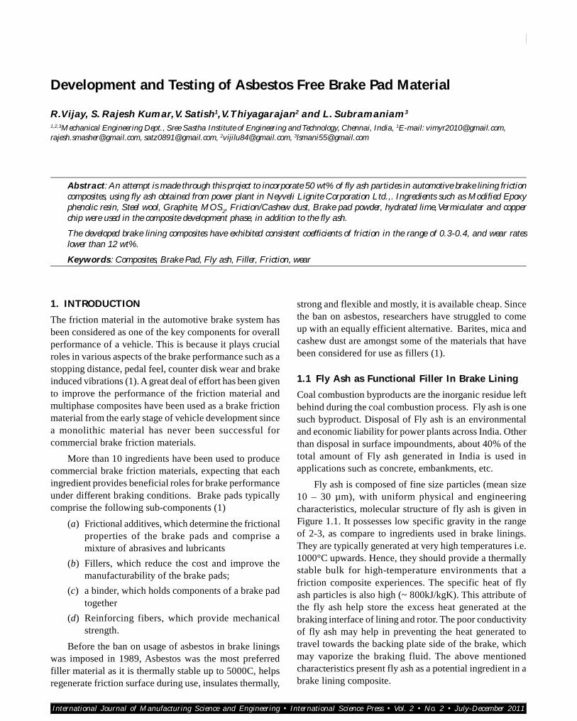
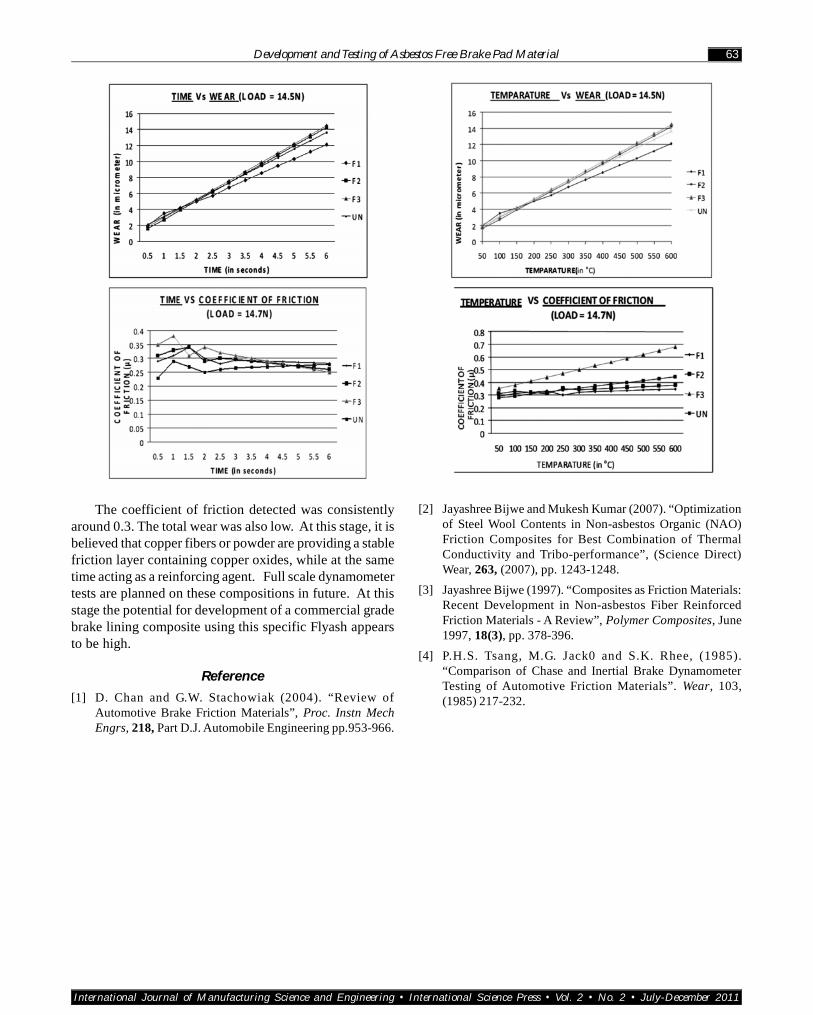
The bulk density of the Fly ash composites was determinedin the range of 1.8 – 2.22 kg/cm2. This is about 40% lighterthan typical commercial brake linings. From the graphs itcan be concluded that F1 is the suitable materialcomposition. As it is having low density, high hardnessand high compressive strength. Also F1 is showing goodfade resistance as it is not Varying with the temperature.
International Journal of Manufacturing Science and Engineering • International Science Press • Vol. 2 • No. 2 • July-December 2011
Development and Testing of Asbestos Free Brake Pad Material 63
The coefficient of friction detected was consistentlyaround 0.3. The total wear was also low. At this stage, it isbelieved that copper fibers or powder are providing a stablefriction layer containing copper oxides, while at the sametime acting as a reinforcing agent. Full scale dynamometertests are planned on these compositions in future. At thisstage the potential for development of a commercial gradebrake lining composite using this specific Flyash appearsto be high.
Reference
[1] D. Chan and G.W. Stachowiak (2004). “Review ofAutomotive Brake Friction Materials”, Proc. Instn MechEngrs, 218, Part D.J. Automobile Engineering pp.953-966.
[2] Jayashree Bijwe and Mukesh Kumar (2007). “Optimizationof Steel Wool Contents in Non-asbestos Organic (NAO)Friction Composites for Best Combination of ThermalConductivity and Tribo-performance”, (Science Direct)Wear, 263, (2007), pp. 1243-1248.
[3] Jayashree Bijwe (1997). “Composites as Friction Materials:Recent Development in Non-asbestos Fiber ReinforcedFriction Materials - A Review”, Polymer Composites, June1997, 18(3), pp. 378-396.
[4] P.H.S. Tsang, M.G. Jack0 and S.K. Rhee, (1985).“Comparison of Chase and Inertial Brake DynamometerTesting of Automotive Friction Materials”. Wear, 103,(1985) 217-232.