Embed Size (px)
Citation preview
1
Development and Demonstration
of CURENT Testbed Systems
Kai Sun
University of Tennessee, Knoxville
Presentation at i-PCGRID Workshop
March 30th, 2016
22
CURENT – NSF/DOE ERC
• Selected by National Science Foundation (NSF) and Department of
Energy (DOE) as one of four for funding (from a few hundred in
response to solicitation across all of Engineering).
• Base budget: ~$4M/year for 5-10 years. Other: $2-3M/year
• First and only ERC devoted to power system wide area controls.
• Partnership across four universities in the US and three international
partner schools. Many opportunities for collaborations.
• 50+ industry members have expressed commitment to join. Presently
have over 31 members.
• Center began Aug. 15th 2011; Third year renewal passed with
recommended funding through 2019.

33
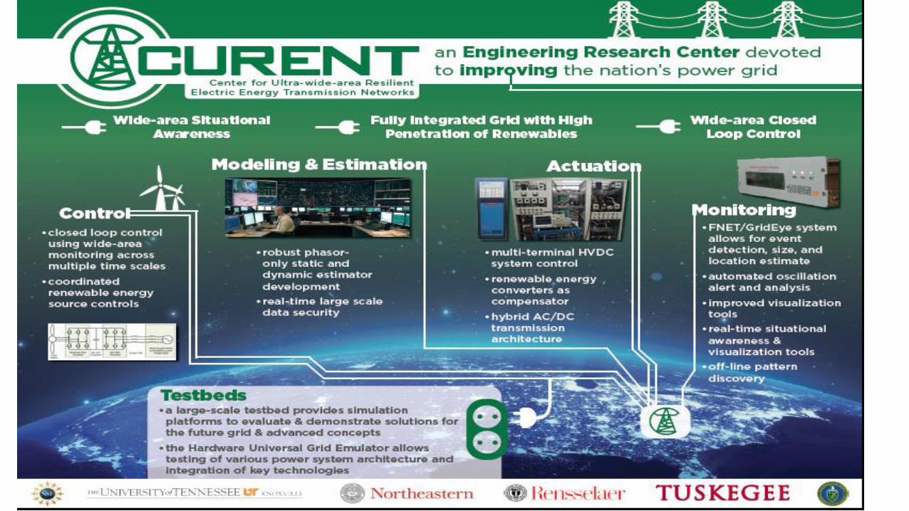
• High penetration of renewable
energy sources
• Flexible DC and AC
transmission
• Accommodate load and
source variability, responsive
load
• Improved situational
awareness, ultra-wide-area
control
Multi-terminal HVDC
Ultra-Wide-Area Resilient Electric Energy Transmission Networks
44 4

55
Day Hour Minute Second Cycle
Device
Substation
Region
Balancing
Authority
Wide Area
Ultra-wide
Area
AGC
LTC
AVR
UFLS
SVC
Fixed Comp.
RAS
Schemes
Unit
CommitmentEconomic
Dispatch
PSS
HVDC
Device
Protection
Today’s Operations Some wide area and some fast but not both
Limited communication
Minimal sensing
Traditional uncoordinated controlsDistributed coordinated actuation with
extensive measurements

66
CURENT Testbeds: Participants and Research Projects
• Faculty members: Leon Tolbert, Fred Wang, Kevin Tomsovic, Yilu Liu, Fran Li,
Kai Sun, Hector Pulgar, Hairong Qi, Stella Sun, Jian Huang (UTK); Ali Abur (NEU);
Joe Chow & Jian Sun (RPI)
• Industry Participants: ABB, GE, Dominion, ORNL, ISO-NE, NYISO, Tektronix,
Vacon, OPAL-RT, National Instruments
• Projects:
1. Large-scale Testbed I – Virtual Grid Simulator with an EMCS (Energy
Management & Control System)
2. Large-scale Testbed II – US Grid Model Development
3. Hardware Testbed – Hardware-based Reconfigurable Grid Emulator
77
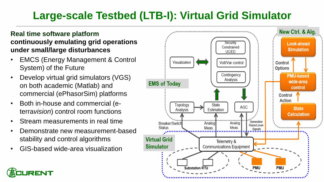
Large-scale Testbed (LTB-I): Virtual Grid Simulator
Real time software platform
continuously emulating grid operations
under small/large disturbances
• EMCS (Energy Management & Control
System) of the Future
• Develop virtual grid simulators (VGS)
on both academic (Matlab) and
commercial (ePhasorSim) platforms
• Both in-house and commercial (e-
terravision) control room functions
• Stream measurements in real time
• Demonstrate new measurement-based
stability and control algorithms
• GIS-based wide-area visualization
88
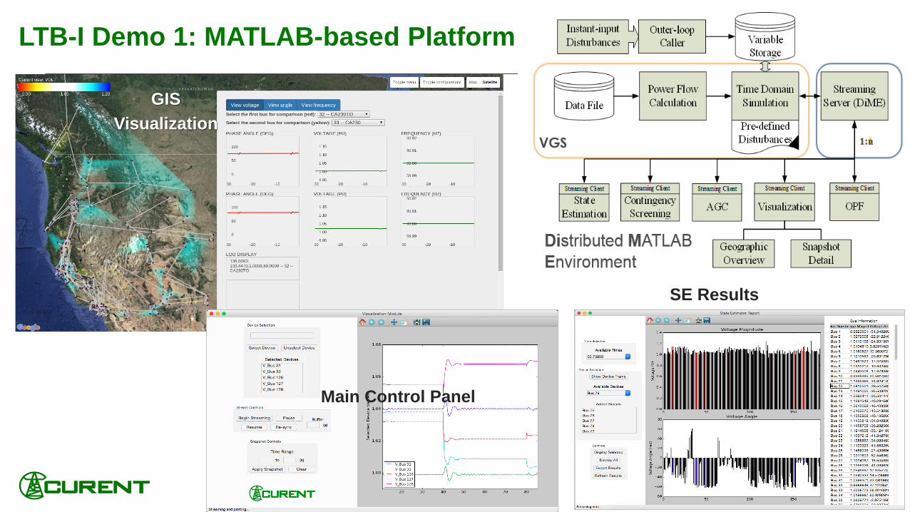
LTB-I Demo 1: MATLAB-based Platform
GIS
Visualization
Main Control Panel
SE Results

99
LTB-I Demo 2: Commercial Platform
ePHASORsim
• Interfaced through same
communication protocol
• Plug n’play functionality with other
software
• Real-time hardware platform
scalable to large systems
GIS
Visualization

1010
LTB-II: US Grid Model Development
Objective: Reduced-order models of US power grids for
demonstration of future interconnections with high renewable
penetration and for design and verification of wide-area control
methodologies.
Research focus:
• EI, WECC EROCT model reduction
• HVDC systems
Multi-Terminal HVDC and overlay HVDC systems in EI and WECC systems
Interconnection of WECC, EI and ERCOT via HVDC
Implementation of HVDC Overlay with renewables
1111
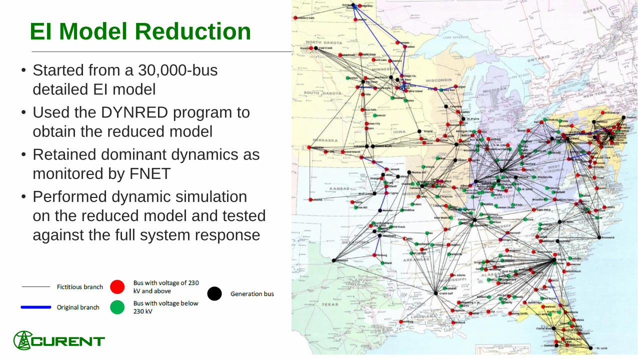
EI Model Reduction
• Started from a 30,000-bus
detailed EI model
• Used the DYNRED program to
obtain the reduced model
• Retained dominant dynamics as
monitored by FNET
• Performed dynamic simulation
on the reduced model and tested
against the full system response
1212
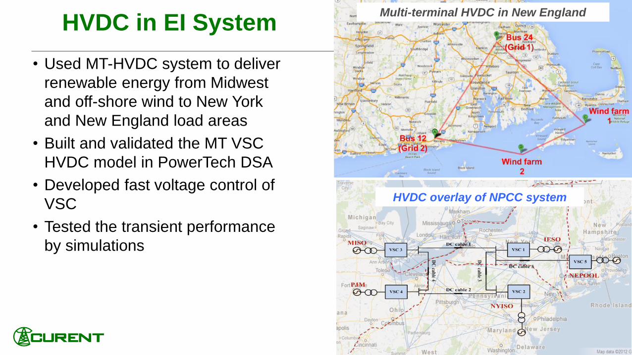
HVDC in EI System
• Used MT-HVDC system to deliver
renewable energy from Midwest
and off-shore wind to New York
and New England load areas
• Built and validated the MT VSC
HVDC model in PowerTech DSA
• Developed fast voltage control of
VSC
• Tested the transient performance
by simulations
Multi-terminal HVDC in New England
HVDC overlay of NPCC system
1313
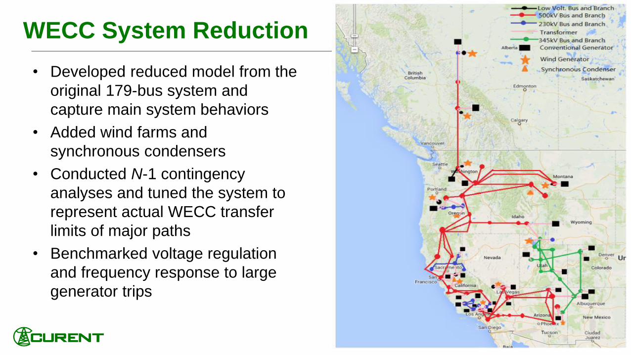
WECC System Reduction
• Developed reduced model from the
original 179-bus system and
capture main system behaviors
• Added wind farms and
synchronous condensers
• Conducted N-1 contingency
analyses and tuned the system to
represent actual WECC transfer
limits of major paths
• Benchmarked voltage regulation
and frequency response to large
generator trips
1414
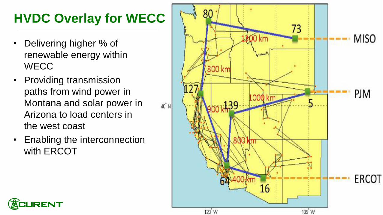
HVDC Overlay for WECC
• Delivering higher % of
renewable energy within
WECC
• Providing transmission
paths from wind power in
Montana and solar power in
Arizona to load centers in
the west coast
• Enabling the interconnection
with ERCOT
1515
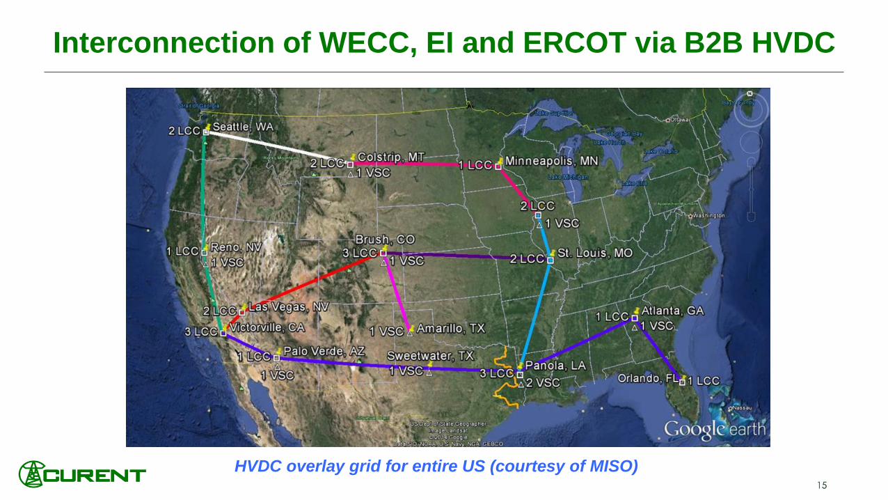
Interconnection of WECC, EI and ERCOT via B2B HVDC
HVDC overlay grid for entire US (courtesy of MISO)

1616
Year 4~6
Generation II
• Reduced North American system model with >
50% penetration of renewables and HVDC
connections
• Extension of frequency & voltage control
models to North American grid and for
damping control and transient stability control
• Communication system modeling including
cyber attacks
• Scenario development for North American grid
Year 7~10
Generation III
• Large model of North American system
with >50% renewables and HVDC
connections
• Fully integrated system model of real
time communication, coordinated
control, actuators, monitoring and load
response
• Detailed scenarios for contingencies
and cyber attacks sufficient to
demonstrate resilience
LTB Demonstration Plan

1717
Hardware Testbed (HTB): Power Converter-based
Reconfigurable Grid EmulatorObjective: hardware implementation and emulation of a power grid that has interconnected generation
sources and loads with real measurement, communication, and control.
Research focus: emulated various grid scenarios with interconnected clusters of scaled-down
generators, loads, and energy storage.
WT II
DC
cab
le 1
DC
cab
le 2
DC cable 4
DC cable 3
VSC 4
1G1 5 6
G2 2
3
G3/WT III
1110
G44
97 8
L7 L9C7 C9
10 km25 km 25 km10 km
110 km 110 km
VSC 3
VS
C 2
VS
C 1
12 13
L12
L13
G14
14
110 k
m
66 k
m
33 km
WT I
Wind FarmWind Farm
Three-Area
System
Area 1Area 2
Area 3
Multi-Terminal
HVDC
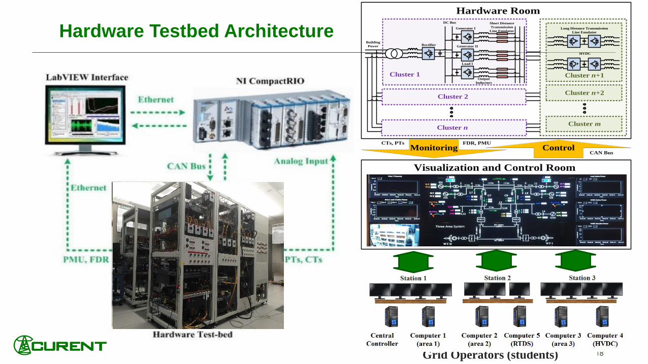
1818
Hardware Testbed Architecture Generator I
Output
Inductors
Generator II
Load I
RectifierBuilding
Power
DC Bus Short Distance
Transmission
Line Emulator
Cluster 1
Cluster 2
Cluster n
Cluster n+1
Long Distance Transmission
Line Emulator
HVDC
Cluster n+2
Cluster m
Monitoring
Hardware Room
Visualization and Control Room
CTs, PTs FDR, PMU
ControlCAN Bus
Grid Operators (students)

1919
Development of the Emulators in HTB
Emulators
Generator Emulator Synchronous generator
Load Emulator
Induction machine
Constant impedance, constant current, and constant power load (ZIP)
Wind Emulator
Wind turbine with permanent magnetic synchronous generator (PMSG)
Wind turbine with doubly-fed induction generator (DFIG)
Solar Emulator Solar panel with two-stage PV inverter
Transmission Line Emulator
Back-to-back converter to emulate AC transmission lines
Energy Storage Emulator Compressed air, batteries, ultra-capacitors, and flywheels
RT Simulator Interface Emulate large scale power system in Real-time Simulator
HVDC Emulator Back-to-back converter to emulate DC transmission
Fault Emulator Emulate three-phase and line-to-line short circuit fault
Voltage Type
Current Type
Year 4
Accomplishment
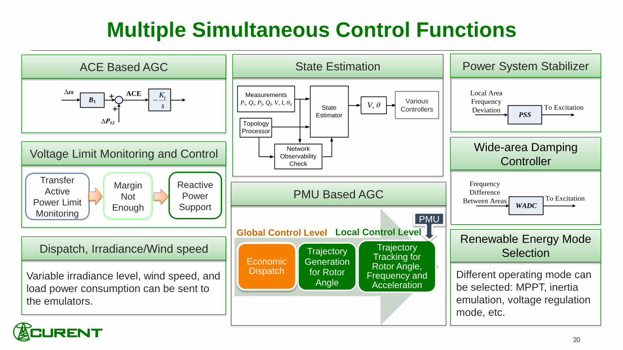
2020
Multiple Simultaneous Control Functions
∆ω
∆P12
B1
ACE
s
KI
ACE Based AGC
Margin
Not
Enough
Transfer
Active
Power Limit
Monitoring
Reactive
Power
Support
Voltage Limit Monitoring and Control
PMU Based AGC
Economic Dispatch
Trajectory Generationfor Rotor
Angle
Trajectory Tracking for Rotor Angle,
Frequency and Acceleration
Global Control Level Local Control Level
PMU
Dispatch, Irradiance/Wind speed
Variable irradiance level, wind speed, and
load power consumption can be sent to
the emulators.
Different operating mode can
be selected: MPPT, inertia
emulation, voltage regulation
mode, etc.
State Estimation
Measurements
Pi, Qi, Pf, Qf, V, I, θij State
Estimator
V, θ
Topology
Processor
Different
Control Block
Network
Observability
Check
Various
Controllers
Local Area
Frequency
DeviationPSS
To Excitation
Power System Stabilizer
Frequency
Difference
Between AreasWADC
To Excitation
Wide-area Damping
Controller
Renewable Energy Mode
Selection
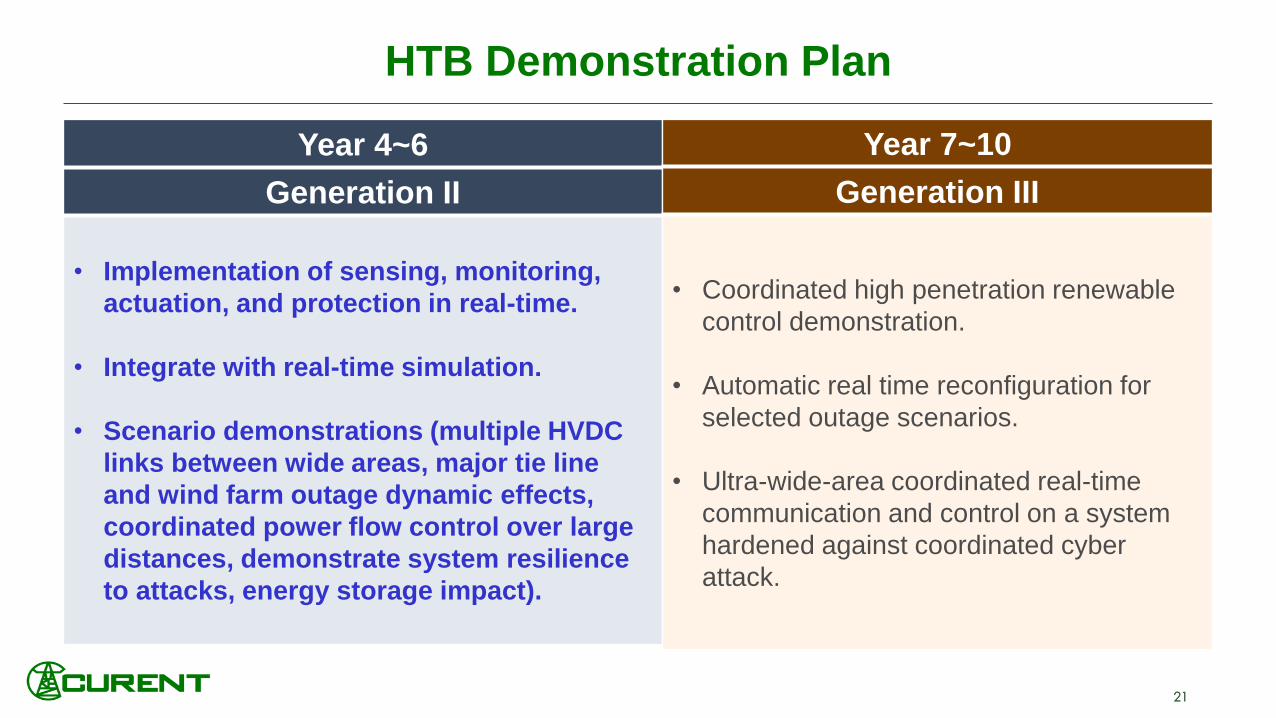
2121
HTB Demonstration Plan
Year 4~6
Generation II
• Implementation of sensing, monitoring,
actuation, and protection in real-time.
• Integrate with real-time simulation.
• Scenario demonstrations (multiple HVDC
links between wide areas, major tie line
and wind farm outage dynamic effects,
coordinated power flow control over large
distances, demonstrate system resilience
to attacks, energy storage impact).
Year 7~10
Generation III
• Coordinated high penetration renewable
control demonstration.
• Automatic real time reconfiguration for
selected outage scenarios.
• Ultra-wide-area coordinated real-time
communication and control on a system
hardened against coordinated cyber
attack.

2222
HTB Demo 1 – High Renewable Penetration
Scenario
• Replace one unit in Area 1 by an onshore wind farm;
together with offshore wind provided by HVDC,
system renewable penetration can reach 80%.
• Event triggered by a HVDC converter failure
Solution
• Frequency and voltage support from
onshore wind farm and the HVDC converters
• Curtailment and voltage mode control when necessary
• Integration of energy storage to further enable grid
support controls
Expected outcome
• System frequency and voltage
within acceptable ranges
0 2 4 6 8 10
0.65
0.7
0.75
0.8
0.85
0.9
0.95
0 2 4 6 8 1059.2
59.4
59.6
59.8
60
60.2
Wind Turbine Active Power (p.u.)
Area Frequency (Hz)
Time (s)
MPPT with inertia emulation
MPPT
Base case with generator
Voltage mode with storage
Voltage mode
HTB scenario test results
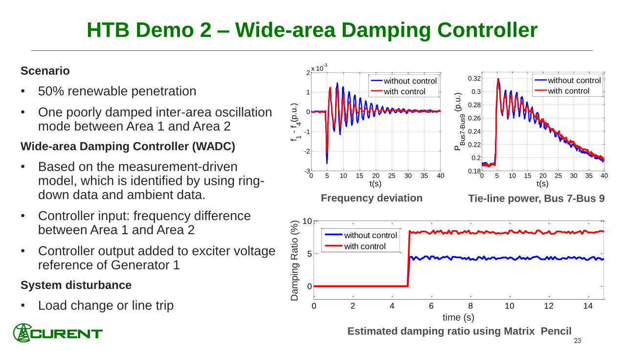
2323
Scenario
• 50% renewable penetration
• One poorly damped inter-area oscillation mode between Area 1 and Area 2
Wide-area Damping Controller (WADC)
• Based on the measurement-driven model, which is identified by using ring-down data and ambient data.
• Controller input: frequency difference between Area 1 and Area 2
• Controller output added to exciter voltage reference of Generator 1
System disturbance
• Load change or line trip
HTB Demo 2 – Wide-area Damping Controller
0 5 10 15 20 25 30 35 40-3
-2
-1
0
1
2x 10
-3
t(s)
f 1 -
f4(p
.u.)
without control
with control
Frequency deviation Tie-line power, Bus 7-Bus 9
0 5 10 15 20 25 30 35 400.18
0.2
0.22
0.24
0.26
0.28
0.3
0.32
t(s)
PB
us7-B
us9 (
p.u
.)
without control
with control
0 2 4 6 8 10 12 14
0
5
10
time (s)
Dam
pin
g R
atio (
%)
without control
with control
Estimated damping ratio using Matrix Pencil

24
HTB Demo 3 – Measurement-Based Voltage Stability Monitoring and Control for Load Areas
• Monitor the transfer margin of each tie lines by a measurement-based method using a multi-terminal network equivalent
• Demonstrating better accuracy than a traditional Thevenin equivalent method
Load Area
External
System

2525
Acknowledgements
This work was supported primarily by the ERC Program of the
National Science Foundation and DOE under NSF Award Number
EEC-1041877 and the CURENT Industry Partnership Program.
Other US government and industrial sponsors of CURENT
research are also gratefully acknowledged.

2626
RTDS Interface with HTB
Two RTDS
interfaces
with the HTB
G1
Area 1
G2 LD7
1 6
2
7HTB
G3
G4
310
4
9
Transmission
Line LD9
Area 2
Emulator 1
Emulator 2 Emulator 3
Emulator 4
Emulator 5Emulator 6
2.45 mH
1.2 mH
0.7 mH
2.5 mH
0.7 mH
0.7 mH10.7 mH
RTDS
Po
wer
Inte
rface
+ -
12
Dig
ital
Inte
rface
Po
wer
Inte
rface
+ -
12
Dig
ital
Inte
rface
12 133 mH
10 mH 6 mH
LD12 LD13
G5
152.5 mH
HVDC1 HVDC2
Area 3 in RTDS
Areas 1 & 2 in HTBRTDS Interface Attributes
• Expanding HTB to more than
40 buses
• Unique system that has both
control and power hardware
interface

2727
CURENT Research Thrusts