Embed Size (px)
Citation preview

IntroductionThis application note gives a global description of Zigbee® smart energy. It gives some hints on how to build Zigbee® smartenergy applications on STM32WB Series microcontrollers and it covers as well sub-GHz operation and LBT topics.
STM32WB can address on 2.4 GHz major smart energy features like for instance metering device.
STM32WB is not necessarily targeting full energy service interface (ESI) device since it may request too many or unsupportedresources like dual radio support for instance (STM32WB does not support sub-GHz operation).
Parts of this document are under Copyright © 2019-2020 Exegin Technologies Limited. Reproduced with permission.
Developing Zigbee® smart energy applications on STM32WB Series
AN5609
Application note
AN5609 - Rev 1 - May 2021For further information contact your local STMicroelectronics sales office.
www.st.com
1 General information
This document applies to the STM32WB Series dual-core Arm®-based microcontrollers.
Note: Arm is a registered trademark of Arm Limited (or its subsidiaries) in the US and/or elsewhere.
1.1 Acronyms and definitions
Table 1. Acronyms and definitions
Acronym Definition
AFA Adaptive frequency agibility
BEIS Business energy and industrial energy
BOMD Battery operated mirrored device
BSI British standards institute
CBKE Certificate based key establishment
CHTS Communications hub technical specification
CPA Commercial product assurance
DRLC Demand response and load control
ESI Energy service interface
GBCS Great Britain companion specification
GSME Gas meter
HA Home automation
HAN Home area network
IHD In-home display
LBT Listen before talk
MISRA Motor industry software reliability association
NOC network operations center
PCT Programmable communicating thermostat
RIB Residential incline block
TOU Time of use
TSCO Trust center swap
ZSE Zigbee smart energy
1.2 Reference documents
1.2.1 Smart energy 1.4• [1] 07-5356-21 Zigbee Smart Energy Standard Version 1.4• [2] 07-5384-23 Zigbee Smart Energy Test Specification Version 1.4• [3] 07-5390-10 Zigbee Smart Energy PICS (Pro-Forma)• [4] Zigbee Smart Energy 1.4 Specification Errata• [5] Zigbee Smart Energy 1.4 Test Specification Errata
AN5609General information
AN5609 - Rev 1 page 2/29
• [6] Zigbee Smart Energy 1.4 PICS Errata• [7] 17-05022-009 Zigbee Smart Energy Standard Test House Notifications for Versions 1.1b, 1.2b and 1.4
1.2.2 Smart energy 1.1bUsually following the approval of a new version of a Zigbee specification, and once Test Houses are open forcertification of the new version, the previous version enters a 6-month sunset period. During the sunset perioddevices can be certified under either version of the specification.Even though versions past 1.1b have been approved, Smart Energy 1.1b is widely used in the North Americanmarket. As a result, in October 2017 the Zigbee Alliance board approved a 5-year extension for certification ofSmart Energy 1.1b devices allowing certifications of both new and existing products under Smart Energy until 8December 2022.• [8] 07-5356-18 Smart Energy 1.1b Standard• [9] 07-5384-20 Smart Energy 1.1b Test Specification• [10] 07-5390-07 Smart Energy 1.1b PICS (Pro-Forma)
1.2.3 Zigbee PRO R22 - 2017• [11] 05-3474-22 Zigbee Specification• [12] 07-5035-08 Zigbee Compliant Platform Test Specification• [13] 08-0006-07 2015 Layer PICS and Stack Profiles (Pro-Forma)• [14] R22 Errata• [15] IEEE 802.15.4-2015• [16] 14-0332-02 Zigbee IEEE 802.15.4 PHY/MAC Test Plan Version 2.0 1.4.
1.2.4 ZCLJust as ZSE 1.4 is not Zigbee 3.0 compliant, it is important to note that ZSE sometimes relies on ZCL 4 eventhough subsequent versions of ZCL have been approved and are in use for Zigbee 3.0.• [17] 07-5123-04 ZigBee Cluster Library, Revision 4• [18] 05-5123-07 Zigbee Cluster Library, Revision 7
1.2.5 OTAThe OTA used for smart energy is slightly different from the Zigbee 3.0 version. When certifying OTA for smartenergy applications these documents are used instead of the Zigbee 3.0 documents.• [19] 16-05028-001 ZCL Chapter 11 OTA• [20] 09-5473-09 OTA Cluster Test Specification• [21] 09-5284-10 OTA Cluster PICS (Pro-Forma)
1.2.6 Relationship between smart energy and other Zigbee® specificationsIn the early stages of Zigbee, as new application areas were adopted such as home automation, commercialbuilding, retail, telecom, the initial approach was to divide the new application areas into profiles, each with aunique Profile ID. This approach proved problematic as many practical applications span profiles. As a result,when Zigbee 3.0 was developed, it did away with profiles, using the home automation (HA) profile ID 0x0104 forall profiles except smart energy, which retained the original profile ID 0x0109. The strict security requirementsof smart energy, specifically authentication using install codes and ECC certificates in CBKE as well as ECDSAsigned images for OTA firmware updates are some of the main reasons why it could not be incorporated intoZigbee 3.0. The integration of smart energy is ongoing, and a future smart energy release will likely eliminate theremaining difference. However as of smart energy 1.4 and Zigbee 3.0 as noted, differences remain in security,OTA, and the profile ID. See the below document:• [22] ETSI EN 300-220
AN5609Reference documents
AN5609 - Rev 1 page 3/29
2 Smart energy overview
Smart energy is one of the primary Zigbee applications. Smart energy is sometimes referred to as smart metering,and while it includes electrical, gas, and water metering, smart energy also includes provisions for:• Scheduling and load control• Pricing and payment (Including in-home or "in-premise" payment terminals)• Customer display units• Electric vehicle management• Solar micro-generation (Net-metering)• Many other features beyond simple metering
Smart energy is part of a global migration by utility providers to intelligent infrastructure, a key component ofwhich is the Smart Grid. A Smart Grid has many components, ranging from generation and distribution to use bythe end consumer.Zigbee smart energy (ZSE) only concerns communication within end-user homes or businesses, a domainreferred to as a home area network (HAN). When the end consumers are located in close proximity, HANphysically overlaps. However, for security reasons each HAN is unique, and messages within a HAN are securelyencrypted to render communication impossible between overlapping HANs.Zigbee is a flexible mesh networking technology. However, for security reasons when Zigbee is used in smartenergy deployments, a star network topology is used. At the center of the star topology is the Zigbee coordinatoror Energy Services Interface (ESI), which in some jurisdictions is referred to as a comms hub. In addition toforming the network and acting as the Zigbee Trust Center, the ESI also maintains a non-Zigbee connectionknown as a back- haul network. This back-haul network is connected to a network operations center (NOC)responsible for managing communication with each individual customer premise or HAN. Depending on thejurisdiction the NOC may be owned by the utility or a third party.In a few instances the Zigbee smart energy specification assumes the existence of a back-haul network. Back-haul network communication protocols are specified by external regulatory bodies and outside the scope ofthe Zigbee specifications. There are often significant differences between back-haul networks used in differentjurisdictions, and for this reason special attention must be given to the regulatory environment of the intendeddeployment zone.Utilities are regulated by regional governments, which in turn put governmental bodies in place to mandate,specify, regulate, and certify the smart energy devices deployed by the utilities. While these governmental bodieshave had a significant impact on the requirements that lead to the development of Zigbee smart energy, theseagencies did not directly participate in the development of smart energy specifications. Zigbee smart energy isdesigned as a global standard, independent of any others jurisdiction. While in some locations governmentalbodies have refined, extended, or restricted certain aspects of the Zigbee smart energy specification (for instancethe UK Government has published the Great Britain Companion Specification (GBCS)), the Zigbee smart energyspecification specifies wireless network operation within the HAN.STM32WB Zigbee solution provides the main foundation on which smart energy applications can be built andcertified for operation in the smart energy HANs. Some jurisdictions may require additional non-Zigbee services,in which case additional regional specifications, services, and certifications may be required. These are outsidethe scope of ZSDK and this document.This document describes how to build smart energy applications that can be tested by an independent test house,and certified compliant to the current certification level required by the Zigbee Alliance.
Note: The scheduling and payment features are not yet supported on STM32WB since that STM32WB does notsupport the following clusters :• Calendar• Device management• Prepayment• Events
AN5609Smart energy overview
AN5609 - Rev 1 page 4/29
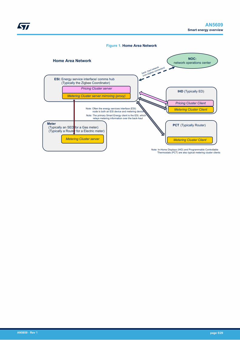
Figure 1. Home Area Network
Metering Cluster Client
Metering Cluster Client
Pricing Cluster Client
Metering Cluster server mirroring (proxy)
Metering Cluster server
NOC:network operations center
Note: In-Home Displays (IHD) and Programmable Controllable Thermostats (PCT) are also typical metering cluster clients
Note: The primary Smart Energy client is the ESI, which relays metering information over the back-haul
Note: Often the energy services interface (ESI) node is both an ESI device and metering device
Home Area Network
Pricing Cluster serverIHD (Typically ED)
PCT (Typically Router)
ESI: Energy service interface/ comms hub(Typically the Zigbee Coordinator)
Meter (Typically an SED for a Gas meter)(Typically a Router for a Electric meter)
AN5609Smart energy overview
AN5609 - Rev 1 page 5/29
3 Smart energy regulatory environment
In the UK, Ofcom regulates wireless transmissions. Globally, in the 2.4 GHz band, Zigbee uses O-QPSKmodulation on 15 channels while sharing for instance this ISM band with WiFi, or the Bluetooth®. The sub-GHz band Annex D of the Zigbee PRO R22 spec defines a special GB-868 transmission mechanism, whichcomplies with European Telecommunications Standards Institute ETSI requirements, but deviates slightly fromthe European convention for this band, hence the name “GB-868” for this PHY. See R22 [11] Annex D for details.Additionally, the department of business energy and industrial strategy (BEIS) regulates the utility companies,a national back-haul network provided by DCC, and the devices that utility companies use in smart energydeployments.The baseline requirements are specified in smart metering equipment technical specifications: Second version(SMETS-II), and devices must implement the necessary device-specific features to comply with the requirementsdetailed in a specific version of this document. Zigbee requirements are only a subsection of SMETS-II,for instance DLMS/COSEM messaging. BEIS also requires compliance with the Great Britain CompanionSpecification (GBCS). There is an additional third document which only applies to Comms Hubs, The CommsHub Technical Specification (CHTS). Devices developed for the UK market must comply with SMETS-II, GBCS,and CHTS for Comms Hubs. It should be noted most requirements imposed by these three specifications areunrelated to the Zigbee interface.An important impact of GBCS on the Zigbee application concerns remote party messages. Remote partymessages are end-to-end encrypted messages (from the back-haul head end system to the recipient device).They are transferred over the back-haul network and then over the Zigbee tunnel cluster to the recipient device.Remote party messages may be DLMS COSEM, ASN.1 or Zigbee ZCL (referred to as GBZ) messages. Thismeans that a device may receive a given message as a regular Zigbee ZCL message or as a GBZ messagevia the tunnel cluster. DLMS COSEM, ASN.1 and the managing of GBZ messages are all outside the scope ofthe ZSDK Zigbee interface (however once the GBZ messages are decrypted they are handled by the ZSDK ZCLclusters in the same manner as a message received directly using the standard Zigbee mechanisms.Products deployed on the UK must be tested by a Zigbee Authorized Test House and certified by the ZigbeeAlliance. Certified devices must be utilizing a R22 Zigbee Compliant Platform. This includes Zigbee IEEE802.15.4 PHY MAC certification covering the RF transceiver and antenna as well as R22 Stack. FollowingR22 Zigbee Compliant Platform Certification the device must also go through ZSE 1.4 Certification using ZSEGolden Units, also at a Zigbee Authorized Test House. ZSE 1.4 Certification is performed ECC (Elliptic CurveCryptography) Test Certificates provided by Certicom. Once Certification is achieved, Production ECC certificatescan be purchased from Certicom. Each device deployed to the field must contain a production certificate. Inaddition to Zigbee Compliant Platform and Zigbee SE 1.4 Certification, products deployed in the UK must undergoa Commercial Product Assurance (CPA) assessment as specified by BSI (British Standards Institute). Part ofCPA is a MISRA (Motor Industry Software Reliability Association) report of which includes the application. Priorto deployment products may also have to go through interoperability testing in conjunction with DCC and or theutility company.
AN5609Smart energy regulatory environment
AN5609 - Rev 1 page 6/29
4 2.4 GHz and sub-GHz operation
Zigbee is built on IEEE 802.15.4-2015 [15] PHY/MAC layers and uses O-QPSK PHY ([15] Chapter 12) inthe 2.4 GHz ISM band and in this band is the same as other Zigbee applications. Smart energy does placesome specific requirements on Zigbee, such as requiring security and providing a mechanism for security keygeneration through CBKE, but on the whole smart energy operation in the 2.4 GHz band is similar to other Zigbeeapplications. However, smart energy is sometimes deployed where the RF characteristics of the 2.4 GHz ISMband are not ideal. The 2.4 GHz ISM band is crowded with other protocols such as WiFi, Bluetooth®, DECT,etc and these can interfere with ZigBee smart energy. 2.4 GHz signals also have a short propagation rangeand require line-of-sight because the signal is readily absorbed by objects in the signal path. In these less thanideal environments the Sub-GHz bands have significantly better performance so smart energy applications alsopermits Sub-GHz operation using the SUN FSK PHY ([15] Chapter 20). Sub-GHz operation in Europe is regulatedby ETSI [22] EN 300-220 (note: ZSE 1.4 was developed when the UK was part of the EU) and the Sub-GHzoperation was developed to meet ETSI Specs.Zigbee PRO Core Specification [11] R22 Annex D defines the GB-868 PHY and facilities to maintain compliancewith the ETSI requirements including: Duty Cycle Monitoring, Adaptive Power Control, and Listen Before Talkchannel access. Note that R22 Annex D refers to the mode of operation as "European Sub-GHz", this issomewhat misleading as it is really designed for operation in the UK. As a result, it is commonly referred toas GB-868. GB-868 uses a starting frequency of 863.25 MHz (starting in channel page 28) whereas EU Sub-GHzbands start at 863.1 MHz (channel page 28). GB-868 also limits the available channels in pages 29 and 30.GB-868 implements "polite" channel access mechanisms, specifically LBT (Listen Before Talk) and AFA (AdaptiveFrequency Control). Because LBT+AFA is used the permissible duty cycle becomes 100s every hour (oreffectively about 2.7% whereas it would be 0.1% without LBT+AFA), see R22 [11].These polite channel access mechanisms as well as adaptive power control do not apply to 2.4 GHz operation.
4.1 Duty cycle monitoringTo ensure that a sub-GHz limits its transmission duty cycle to less than the regulatory limit, duty cycle monitoringis implemented. The duty cycle monitoring is performed through a combination of MAC and application levelfeatures. The MAC monitors its transmissions using a set of buckets that span a 1-hour interval. Transmissionsduring the bucket interval accumulate in the current bucket until the end of the bucket interval at which point anew bucket is started and the oldest bucket discarded. The sum of all the buckets is the total transmission duringthe last hour and this is available as a PIB parameter. When the regulatory limit is reached the MAC suspendstransmission until enough buckets have expired. Before the regulatory limit is reached, there are lesser thresholdswere only certain transmissions are permitted and this is reflected in the duty cycle mode accessible through aPIB value denoting the mode as NORMAL, LIMITED, CRITICAL or SUSPENDED.
4.2 Listen before talk (LBT)The 2.4 GHz O-QPSK PHY uses carrier sense multiple access as the channel access method. CSMA requirestransmitters to avoid collisions by listening for a carrier and only transmitting if a carrier is not detected (andotherwise backing off for a random interval before trying again). CSMA channel availability is determined bylooking for a carrier, for instance a signal using the same modulation on the desired frequency. With LBT (listenbefore talk), the would-be transmitter monitors the energy on the desired frequency. The distinction is subtle butimportant, LBT is more likely to detect a transmission from a source using a different modulation scheme: it is amore polite channel access mechanism. The GB-868 PHY uses LBT instead of CSMA to comply with the ETSIregulations.
4.3 Adaptive frequency agility (AFA)The GBCS and SMETS-II specifications were developed when the UK was part of the EU and fell under CEPTand ESTI regulations. To achieve 2.7% duty cycle, adaptive frequency agility is required. Zigbee meets thisrequirement through the frequency agility feature, see [11] Annex E, sections 2.4.3.3.10, and F.2.2. To supportfrequency agility, a device must be capable of operating on multiple channels. The section 5.8.1 of Zigbee SmartEnergy Standard Version 1.4 ([1]) specifies the preferred 2.4 GHz channels 11, 14, 15, 19, 20, 24 and 25 andD.14 specifies the Sub-GHz channels on pages 28, 29, 30, and 31 and using ZbStartupConfigGetProSeDefaults()populates the startup configuration with these SE default channels.
AN56092.4 GHz and sub-GHz operation
AN5609 - Rev 1 page 7/29
Prior to forming a network, a scan is performed to locate a channel with the least likelihood of interference. Basedon these scan results a network is formed on a preferred channel (or a channel on each 2.4 GHz and Sub-GHzbands in the case of a dual band ESI). However, conditions change over time and after repeated interference on achannel, the network may have no choice but to move to a new channel to avoid interference.This behavior is known as frequency agility or adaptive frequency agility and support that allows applications toimplement it is a standard feature of ZSDK.
AN5609Adaptive frequency agility (AFA)
AN5609 - Rev 1 page 8/29
5 Trust center swap out (TSCO)
Smart Energy deployments are often in the range of millions of individual Smart Energy HAN networks. Eachindividual network is expected to be long lived, with a potential lifetime of decades. With so many devicesoperating over such long a period of time, there might problems with a few individual devices on some networks,and some might be replaced. Replacing most devices is relatively straightforward, the replacement device issimply commissioned and added to the network in the same way as the original device was during the originalprovisioning.Replacement of the ESI/Comms Hub (for instance the Trust Center) is not as straightforward. The Trust Centeris the network coordinator (with the special short address 0x0000) and contains Install Codes and Link Keys(established via CBKE) with all of the devices on the network. Replacing the ESI is different from other devices onth network. As a result, the Trust Center Swap Out, or TSCO, procedure is required.TCSO allows a Trust Center to be replaced without compromising the security of the network. The network key isnever transmitted unencrypted, and neither the network key nor the individual link keys are ever used outside therespective devices.When swapping TCs, the Extended PAN ID is retained and transferred to the new TC, allowing devices to locatethe new TC. In addition, the existing link keys are hashed and used as a pre-configured link key on the newdevice. The original link key cannot be reconstructed from the hash.
AN5609Trust center swap out (TSCO)
AN5609 - Rev 1 page 9/29
6 Building smart energy applications using ZSDK cluster templates
Smart energy devices interact using ZCL clusters. Much of the work of implementing a smart energy deviceconsists of completing the application specific functionality defined by those clusters. The ZSE [ref 1.4] andZCL [ref 4] specifications define the interfaces and the required functionality. ZSDK provides template clusters,implementing the communication requirements and providing a template into which a smart energy applicationcan be built.A smart energy HAN consists of several nodes. In many cases a node consists of a single device type asdefined in the smart energy specification. It is also possible that a node may support the functionality of morethan one device type. Often the energy services interface (ESI) node is both an ESI device and metering device.Other nodes are generally a single device type such as the In-home display (IHD), programmable communicatingthermostat (PCT), smart appliance, and prepayment terminal devices.
6.1 Smart Energy device typesEach physical Smart Energy device consist of one (or more) of the device types defined in the Smart EnergySpec, including:• Energy Services Interface (ESI)• Metering Device• In-Home Display (IHD)• Programmable Communicating Thermostat (PCT)• Load Control Device• Smart Appliance• Prepayment terminal => not available on STM32WB• Physical Device• Remote Communications Device• Linky ERL device => not available on STM32WB• Range Extender
The ESI (Energy Services Interface) plays a special role in the network. Firstly it is normally the coordinator andTrust Center. Secondly, it is the device connected to the back-haul network.In the UK Market the Zigbee ESI is part of a device known as a Comms Hub. Similarly other device typeshave UK specific names such as ESME, GSME and PPMID. These are defined in the Great Britain CompanionSpecification (GBCS) which is outside the scope of Zigbee and this Document.The Zigbee Smart Energy spec defines a method for new devices to join a Smart Energy network in the form ofan install code, often printed on the device itself. The install code must be conveyed over the back-haul networkto the ESI, where it is used to create a Link Key on the Trust Center the device uses to join the network.
6.2 Overview of Smart Energy clustersSmart Energy clusters provide base functionality as ZCL commands and attributes. Each specific implementationuses these features in different ways depending on the actual device, jurisdiction, and the utility company.A Smart Energy Device is deployed to a specific market, and must be adapted to meet a specific set ofrequirements dictated in particular by:• The business practices of the utility company• The back-haul network provider’s infrastructure• Regional and national governments
For example:• One utility company may use a residential incline block pricing structure, where others may use time of use
pricing.• One regulator may require that customers must be issued emergency credit under certain circumstances.• Sub-GHz channels are restricted regionally, and some regions have restrictions on power output and duty
cycle. All of these requirements mean that a device must be targeted to a specific market.
AN5609Building smart energy applications using ZSDK cluster templates
AN5609 - Rev 1 page 10/29
Many of these requirements directly impact the design and business logic of the application. When designing anapplication these aspects must be taken into consideration. Some aspects are related to application use of theclusters; for example, some jurisdictions regulate how many and what type of calendars are used. Other aspectssuch as non-Zigbee legacy and proprietary messages tunneled over the tunneling cluster are completely outsidethe Zigbee specification.ZSDK provides generic cluster templates that can be used to support the business logic in market specificapplications for any device type. The following sections describe these generic cluster templates; the attributes,functions, callbacks, etc. that are required. The ZSDK cluster templates are developed to be certifiable by theZigBee Alliance with the Zigbee Smart Energy Specification. Application development consists of implementingan often rich set of specific business logic required for a specific device in a specific Smart Energy market.
AN5609Overview of Smart Energy clusters
AN5609 - Rev 1 page 11/29
7 SE mandatory and optional clusters
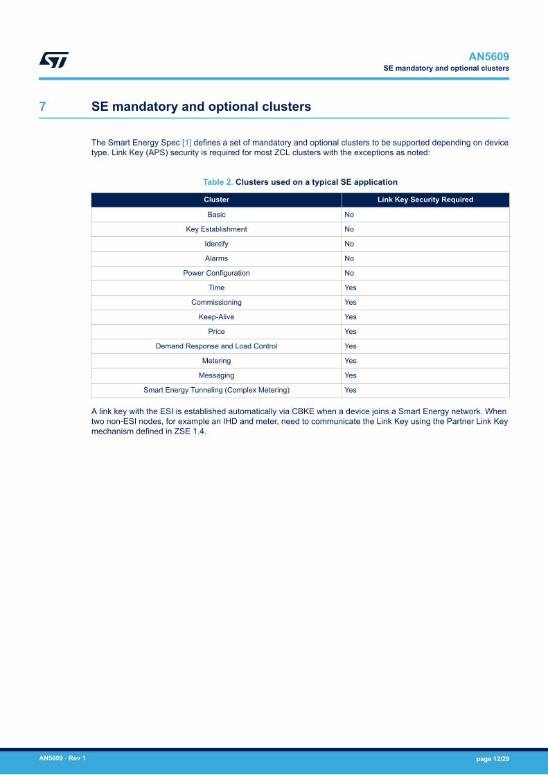
The Smart Energy Spec [1] defines a set of mandatory and optional clusters to be supported depending on devicetype. Link Key (APS) security is required for most ZCL clusters with the exceptions as noted:
Table 2. Clusters used on a typical SE application
Cluster Link Key Security Required
Basic No
Key Establishment No
Identify No
Alarms No
Power Configuration No
Time Yes
Commissioning Yes
Keep-Alive Yes
Price Yes
Demand Response and Load Control Yes
Metering Yes
Messaging Yes
Smart Energy Tunneling (Complex Metering) Yes
A link key with the ESI is established automatically via CBKE when a device joins a Smart Energy network. Whentwo non‑ESI nodes, for example an IHD and meter, need to communicate the Link Key using the Partner Link Keymechanism defined in ZSE 1.4.
AN5609SE mandatory and optional clusters
AN5609 - Rev 1 page 12/29
8 General clusters which do not require link key security
8.1 Basic clusterThe basic cluster is unique in that it is (normally) allocated automatically when the endpoint is created usingZclAddEndpoint(), and not allocated by the application. However, it is the applications responsibility to setattributes appropriately. Special helper functions are provided to assist in this process. Once all endpoints areallocated, the attributes of the Basic should be updated using ZbZclBasicWriteDirect(), specifying an endpointZB_ENDPOINT_BCAST. This updates the Basic cluster attributes on all endpoints.The following attributes must be set in this way:• ZCL_BASIC_ATTR_APP_VERSION• ZCL_BASIC_ATTR_STACK_VERSION• ZCL_BASIC_ATTR_HARDWARE_VERSION• ZCL_BASIC_ATTR_MFR_NAME• ZCL_BASIC_ATTR_MODEL_NAME• ZCL_BASIC_ATTR_DATE_CODE• ZCL_BASIC_ATTR_POWER_SOURCE• ZCL_BASIC_ATTR_SW_BUILD_ID
Refer to the documentation on the Basic cluster and ZSE spec for the correct values to which these attributesshould be set.
8.2 Certificate based key establishment (CBKE) clusterThe CBKE cluster is allocated automatically at startup when either suite 1, suite 2 or both suites are enabled,and certificates are defined in the ZbStartupCbkeT fields of ZbStartupT. See the Section 12 Device startup on asmart energy network and the ZSE 1.4 Specification for more information.
8.3 Identify clusterThe Identify cluster is an optional cluster for Smart Energy devices. However, making this cluster available isrecommended to assist installers in verifying individual units. Other specifications such as BDB impose additionalfunctionality on the Identify cluster, such as Finding and Binding. Such functionality is not used in Smart Energynetworks where the only purpose of the cluster is to validate that the correct physical unit is being addressed.
8.4 Alarms clusterThe Alarms cluster is required when alarms are supported on other clusters, such as Basic, Metering, andPrepayment. When the application implements alarm support on one of these clusters, it must also create analarm server cluster on the same endpoint as the cluster which generates the alarm. When the cluster applicationneeds to generate an alarm it uses the ZbZclClusterSendAlarm() helper to generate the alarm.Please see the documentation of the individual clusters for definitions of the alarms and alarm codes, and thedocumentation of the Alarm cluster for additional information. The ZSDK APIs can be found in Application NoteAN-029 and AN-052.
8.5 Power configurationThe power configuration cluster is optional. It consists of a number of attributes clients may read to determine thecharacteristics of a device’s power supply, including main power or battery parameters.See the cluster documentation for more details.
AN5609General clusters which do not require link key security
AN5609 - Rev 1 page 13/29
9 General clusters which do require link key security
9.1 Time clusterClocks in a Smart Energy network are synchronized using the time cluster, with the ESI acting as the serverand clock master. Devices which rely on time can query the ESI and synchronize their clocks with the ESI. Thedevices must use APS link key security on all Time cluster messages and only accept or respond to link keysecured requests.
9.2 Commissioning clusterThe commissioning cluster is listed as an optional cluster in the spec to allow for the possibility configuringdevices wirelessly using a special commissioning tool. The ZSE Spec neither defines how this is done, norprecludes it. In practice the availability and use of the cluster would be dependent on jurisdiction, as manydeployments do not make use of the commissioning cluster. When available, the commissioning cluster must onlybe accessible via APS Link Key secured messages.
9.3 Keep-Alive clusterThe Keep-Alive cluster is created automatically by the stack when CBKE is used. It is part of the mechanismby which Smart Energy devices detect loss of communication with the trust center. This loss of communicationresults in a sequence of retries, network re-join attempts, and ultimately an attempt to join a new trust center(TCSO). Applications should not declare instances of the Keep-Alive cluster. However, they do need to implementa device specific re-join sequence. See Section 12 Device startup on a smart energy network for more details.
AN5609General clusters which do require link key security
AN5609 - Rev 1 page 14/29
10 Smart Energy clusters
This section contains information regarding the following Smart Energy clusters:• Demand response and load control (DRLC)• Messaging• Metering• Price• Tunneling
10.1 Demand response load control clusterA smart grid may not be able to meet the total demand during peak periods. For example, during a heat wavethe demand for electrical power for heat pumps may exceed supply, resulting in rolling blackouts. The Demandresponse load control (DRLC) cluster provides a mechanism for utilities to shed load, better manage the grid, andeven prevent failure under peak load conditions.DRLC assumes an out of band mechanism from the head end over a separate back-haul network to the ESI. Theapplication on the ESI responds by issuing DRLC events to devices on the Zigbee Smart Energy HAN. The termEvent used in the ZSE Spec is somewhat misleading; a Load Control Event is a request from the ESI for a SmartEnergy Device to change behavior for some duration, possibly at some point in the future.An example Load control event may instruct a Programmable Controllable Thermostat (PCT) to adjust itssetpoints (less heating or cooling). Although originally intended for thermostats, DRLC has been extended toa range of devices such as water heaters, swimming pools, appliances, commercial loads, and electric vehicles.Load Control Events contain an Event Control field for randomizing the start time and/or the duration in order toprevent a scenario where potentially many thousands of devices across a Smart Grid simultaneously turn on oroff.A device does not always comply with a Load Control Event. Events are generally voluntary and devices may"opt-out" of participation. In some applications the occupant needs to "opt-in" to an event and the utility may offeran incentive, such as reduced rates, for participation.The devices respond to Load Control Events by sending Report Event Status commands to the ESI. A singleLoad Control event often generates multiple Reports, each with a different status, such as "opt-in"/"opt-out", eventstarted, event completed, event canceled, etc.The cluster roles in the DRLC cluster may appear reversed from normal. The ESI is the DRLC server and theload-controlled device is the client. Clients support writable attributes to allow the ESI to assign groups, controlrandomization of start time and duration, as well as setting the device class.
10.1.1 DRLC server cluster on the ESIOn the ESI, the sever cluster is created using:ZbZclDrlcServerAlloc()Two callbacks are supported, one to receive asynchronous report status commands from the client:void (*report_status)(struct ZbZclClusterT *clusterPtr, struct ZbZclAddrInfoT*srcInfo, struct ZbZclDrlcStatusT *status, void *arg);Status contains the Event Report Status command returned by the client.The second server callback receives the response to a Get Scheduled Events request:enum ZclStatusCodeT (*get_events)(struct ZbZclClusterT *clusterPtr, structZbZclAddrInfoT *srcInfo, struct ZbZclDrlcGetEventsReqT *req, void *arg);The ESI server can request Get Schedule Events using ZbZclDrlcServerCommandEventReq(). If no events arefound on the client a status of ZCL_STATUS_NOT_FOUND is returned in the callback.The server can also cancel a single event using ZbZclDrlcServerCommandEventReq() or all events usingZbZclDrlcServerCommandEventReq().DRLC client cluster on the Controlled DeviceOn the controlled load device, the client cluster is created using:ZbZclDrlcClientAlloc()
AN5609Smart Energy clusters
AN5609 - Rev 1 page 15/29
Because they are mandatory, all client attributes are created automatically and set to default values according tothe Specification.The DRLC client cluster manages the events received from the ESI internally, using timers to signal theapplication to start and stop events as needed. For this reason the client cluster automatically generates theReport Event Status callbacks with event code Command Received. See ZSE 1.4 [1], Figure D-8 and D-9.The application must not attempt to also send these reports.The client cluster interacts with the application via two callbacks provided to the cluster when it is instantiated viathe alloc function:bool (*start)(void *arg, struct ZbZclDrlcEventT *event)void (*stop)(void *arg, struct ZbZclDrlcEventT *event)The start callback should return true when the application wants the stop callback to be invoked at the end of theevent. Typically when an error occurs in the start callback it returns false indicating to the client cluster that it doesnot want a stop callback at the end of the event.The client application may decide to asynchronously send Reports to the ESI using theZbZclDrlcClientCommandReportStatusReq() function. This is typically used for Opt-In and Opt-Out Event statusreports. Because the DRLC client cluster manages the events, it also issues event cancellation status reports.If an event is canceled between the start and stop callbacks the stop callback is invoked with the cancellationevent allowing the application to take appropriate action.In exceptional circumstances the DRLC client can lose the active events. This could happen for instance in anunexpected power cycle and restart from persistence of the load control device. In this case during restart theclient should request that events be re-issued using:ZbZclDrlcClientCommandGetEventsReq()This results in the ESI reissuing the events it has in place for this load control device. This re-establishesthe internal table and result in the start callback being called for active load control events. If the loadcontrol device is offline when the the stop callback should be called it cannot be called as a result of issuingZbZclDrlcClientCommandGetEventsReq(). For this reason, the applications must assume the initial power-upstate, which is the same as after completion of the stop callback. In this way the ESI and load control deviceremains synchronized, even in the rare event of temporary loss of communication due to a restart.
10.2 Messaging clusterThe messaging cluster provides a mechanism for an ESI to display simple textual messages on the display ofa Smart Energy device, typically an IHD (In-Home Display), PCT (Programmable Communicating Thermostat),Smart Appliance or Prepayment Terminal. The device must has a display capable of displaying a short textualmessage.Messages are sent from the ESI server to the device client (note that in some senses this is the opposite of theconventional client/server roles). Messages my require a confirmation that the user has received the message("okay") and possibly a simple "yes/no" response.On the ESI the server cluster is instantiated using ZbZclMsgServerAlloc() and the application providescallback functions to receive responses from the client. The ESI sends a message to the client usingZbZclMsgServerDisplayMessageReq() or ZbZclMsgServerDisplayProtectedMsgReq() when the message needsto be password protected. The display message request includes the message text, start time and duration inminutes. A message control field specifies the importance, whether receipt confirmation is required and whethera yes/no response is required (enhanced confirmation). The specification message control includes support forInterPAN transmission. This is included for legacy applications. InterPAN messaging is insecure and its use hasbeen depreciated.The client application creates the client cluster using ZbZclMsgClientAlloc(). On receipt of the display_messagecallback if a receipt confirmation or enhanced confirmation is required it calls ZbZclMsgClientConfReq() to sendthe confirmarion message back to the ESI.The ESI may cancel a specific message using ZbZclMsgServerCancelMessageReq() or all active messages withZbZclMsgServerCancelAllReq().In the event of temporary loss of communication of the display device with the ESI, it should synchronize withthe ESI by sending a ZbZclMsgClientGetLastReq() request it to re-send any Display Messages that had beenpreviously sent. It is also possible that the client is still displaying a message that has been cancelled by the ESI.If still displaying a message it can use ZbZclMsgClientGetMsgCancelReq() to check wether the message shouldbe cleared.ZbZclMsgClientGetLastReq() and ZbZclMsgClientGetMsgCancelReq()
AN5609Messaging cluster
AN5609 - Rev 1 page 16/29
10.3 Keep-AliveSee Section 9.3 Keep-Alive cluster.
10.4 Metering clusterThe metering cluster is arguably the central cluster in Smart Energy applications. An electric, gas or water metersupports a server instance of the meter cluster, exposing a potentially diverse range of attributes to other SmartEnergy devices. The primary Smart Energy client is the ESI, which relays metering information over the back-haulto the head-end system. In-Home Displays (IHD) and Programmable Controllable Thermostats (PCT) are alsotypical metering cluster clients. In many deployments the ESI and Meter are physically the same device, eventhough they are logically distinct in terms of their operation.Some meters (typically gas or water meters) are battery powered and sleepy, and therefore not always available.This poses a problem for clients that require on-demand access to metering data. In these situations a mirroringfacility is implemented, where the sleepy meter sends its meter data to an instance of the meter server cluster onthe ESI, which mirrors the data, thereby making it always available to devices on the network.The attributes of the metering server are divided into the following attribute sets:• Reading Information Set• TOU Information Set• Meter Status• Formatting• Historical Consumption• Load Profile Configuration• Supply Limit• Block Information (Delivered)• Alarms• Block Information (Received)• Meter Billing Attribute Set• Supply Control Attribute Set• Alternative Historical Consumption
Attributes are intended to support a wide array of applications, and there are definitions for a large numberof attributes to account for a diverse range of possible deployment scenarios. However, there are only a fewmandatory attributes, and implementation of the remaining attributes is determined by the requirements of thespecific deployment. Even though these attributes are optional in the Zigbee Smart Energy specification, theirinclusion may be mandated by external requirement such as regional specifications. Definitions of many of theoptional attributes are disabled in the ZSDK template and can be included as needed by the application.
10.4.1 Metering cluster attribute formattingThe mandatory attribute CurrentSummationDelivered is main meter reading value. Also mandatory are theMeteringDeviceType (such as Electric, Gas, Water and Thermal), UnitofMeasure (kWh, m3, BTU, etc.), andSummationFormatting attributes. CurrentSummationDelivered comes directly from the sensor, to obtain the actualdisplayed value the SummationFormatting attribute is used to format the value with the number of digits to theright and left of the decimal point. There are also two optional attributes Multiplier and Divisor, which if presentand nonzero, are used to scale the meter reading value. The server provides the following attributes:• CurrentSummationDelivered• SummationFormatting• Multiplier, Divisor• MeteringDeviceType• UnitsofMeasure
And the client combines these to correctly interpret and display the value. See [ZSE 1.4], Table D-24 forformatting examples.In general, meters measure the quantity delivered. In some cases the meter may "run backward"; as in the caseof solar photovoltaics generating electricity during the day and feeding it back into the grid at night. In such casesthere are also "received" attributes available to record the amount energy delivered back to the grid.
AN5609Keep-Alive
AN5609 - Rev 1 page 17/29
Utilities seldom charge at flat rate. The complexities result in the need for a separate price cluster. It alsoimpacts the attributes of the meter cluster. Two common schemes are Residential Incline Block (RIB) and TimeOf Use (TOU). With RIB blocks of usage within a billing period are assigned. Usage up to the first block (forinstance a specific number of kWh) are assigned the lowest pricing tier. If and when the blocks are exceededusage in that block is billed at successively greater pricing tier. The block associated attributes including theCurrentBlockPeriodConsumptionDelivered, CurrentBlock, CurrentBlockReceived, etc. are all used when RIBpricing is used and not supported otherwise. When Block pricing and combined Tier-Block pricing is used, eachunit of consumption is then added to one specific attribute in the Block Information Attribute Set Delivered orReceived.When TOU pricing is in place, the consumption is metered depending on the time of day each assigned a Tier.Each unit of consumption is then added to a tier specific attribute in the TOU Information Attribute set.There are many more potential attributes organized into attribute sets including meter status, historicalconsumption, supply limits, meter billing, supply control and alternate historical consumption.These optional attributes are only enabled and used as dictated by the requirements and business logic of thehead end system. A specific meter contains an application specific implementation with a subset.
10.4.2 Metering cluster alarmsThe metering cluster supports a wide range of potential alarms. The alarms available depend on the meter type(electric, gas, water, thermal). The Alarms Attribute set contains a set of alarm masks that allow an alarm client toselectively enable or disable generation of specific alarms. See [Ref ZSE 1.4] section D.3.2.2.9 for the definitionof the alarm codes and alarm mask attributes.When the meter cluster server application detects an alarm condition it posts the alarm using the helper functionZbZclClusterSendAlarm() from the meter server cluster. This results in generation of the alarm from the instanceof the alarm server cluster on the same endpoint as the meter cluster server. See the alarms section of the [RefZSDK ZCL API] for more details.
10.4.3 Metering cluster and Fast PollingIt is typical for meter attributes to be updated every 30 seconds. In some cases, such as when a useractively watching an IHD screen, it is desirable to increase the update frequency. Zigbee provides the Fast Pollmechanism to enable this kind of temporary increase. Meter applications advertise the normal frequency in theDefaultUpdatePeriod attribute and the quickest supported fast poll as the FastPollUpdatePeriod attribute value.The client requests fast polling by issuing a RequestFastPolling command to the server.Note that the meter cluster fast polling mechanism is unrelated to the poll control cluster.
10.4.4 Metering cluster profilesCumulative usage on an hourly or daily basis is not fine grained enough to understand consumption patterns. Aclient could attempt to construct this information by performing regular reads, but this approach suffers issues dueto time synchronization between client and server, and dealing with the possibility of missed reads. In order toresolve this issue, the metering cluster introduces the concept of profiles.With profiles, the meter automatically accumulates the Consumption Delivered, Consumption Received, ReactiveConsumption Delivered, and/or Reactive Consumption Received in a fixed number of buckets, up to the value ofthe MaxNumberOfPeriodsDelivered attribute. Each bucket covers a covering a fixed time interval as given by theProfileIntervalPeriod attribute.Meter clients can request this data using ZbZclMeterClientCommandGetProfileReq().On the server when one of these commands is received, the application provided get_profile callbackis invoked. The application then gathers the data it was accumulating in the background, and callsZbZclMeterServerSendGetProfileRsp() to return the Profile data to the client.On the client, the callback provided in the call to ZbZclMeterClientCommandGetProfileReq() is invoked with theGet Profile Response.
10.4.5 Metering cluster mirroringA mirror is a duplicate meter cluster server instance located on a proxy device. It is used when the actual meter ison a sleepy node and not generally accessible. The mirror, which typically resides on the ESI, is always availableto provide the metering data. A mirror can be distinguished from a physical meter by the Device Type attributespecial "mirrored" device types are used and differentiate a physical meter from it’s mirror.
AN5609Metering cluster
AN5609 - Rev 1 page 18/29
The meter cluster is mirrored using a one-way mirror. The mirror mechanism is defined in [ref ZSE] sectionD.3.4.4 Mirroring.An ESI with the ability to act as a mirror provides a mirror discovery endpoint. This endpoint has, possiblyin addition to other clusters, an instance of the Basic Cluster with the PhysicalEnvironment attribute set to1 and a (potentially partial) instance of the Metering Server cluster. A sleepy meter that requires a mirrordiscovers the ESI, determines that it has mirroring capacity through the PhsicalEnvironment attribute and sendsa RequestMirror command to the Metering Server cluster on the discovery endpoint. The ESI must then create anew mirror endpoint using ZbZclAddEndpointNoBasic() because the instance of the basic cluster on this endpointis a mirror of Basic cluster on the mirroring device (not the ESI’s Basic Cluster). The ESI adds a new Basic Serverand Metering Server clusters to the new mirror endpoint and responds to the Request Mirror command with theendpoint ID of this new endpoint.The application on the mirroring device then pushes the contents of its Basic Server and Meter Server cluster tothe mirror using Attribute Reports. The sleepy meter is periodically wake, when it does meter server attributes thathave changed are pushed to the mirror using Attribute Reports.
10.5 Price cluster
10.5.1 ESI pricing serverIn a Smart Energy HAN the ESI is the server for providing pricing information to the HAN clients. devices. Thiscluster is highly configurable. Only the GetCurrentPrice and PriceAcknowledgement commands are mandatory,all other commands and attributes are optional. Only a fraction of the optional commands and attributes areimplemented in an actual device, as needed to suit the specific regulatory and market requirements where it isdeployed. The optional commands and attributes implemented are also to an extent driven by the needs of theapplication running on the device.The ESI instantiates a Price Server instance by calling ZbZclPriceServerAlloc() and providing callback functionsfor the mandatory GetCurrentPrice and PriceAcknowledgement messages. There is also support for several ofthe more common optional commands and commands that are optional for Zigbee but mandatory in certainjurisdictions such as the GB market. If a callback is set to NULL, it is handled as an unsupported command.The special "optional" callback is provided for the application to add support for the less common commands. Ifneeded the application must implement custom handlers for these commands.Because all attributes are optional, ZbZclPriceServerAlloc() does not allocate any attributes. The application mustallocate any optional clusters required. Attributes are divided into a number of attribute sets by the functionof the attribute. The sets are also organized into two banks. The first bank is primarily for pricing concerningdelivered consumption, the second bank duplicates the consumption attributes however is instead for the pricingof received energy. The received sets are only used when needed. Each set and the individual attributes areoptional and depend on market requirements.When used the price tier and block threshold attributes often occur in large blocks. In order to save space helpermacros are provided to the application and ensure the correct resulting attribute id.ZCL_PRICE_SVR_ATTR_TIERN_LABEL(1)ZCL_PRICE_SVR_ATTR_TIERN_LABEL(2)...Pricing information is also distributed using a publish mechanism. The devices need to stay up to date with pricingdata bind to the ESI pricing server cluster and receive publish commands such as PublishPrice. When priceschange the ESI calls a publish command such as ZbZclPriceServerSendPublishPrice() publish the change tobound clients.
Price client device
Devices requiring pricing information instantiate a instance of the price client cluster using ZbZclPriceClientAlloc()provide a callback for publish price command. The remaining publish commands are optional and the applicationmust implement its own handler using the generic optional callback.Clients can send a GetCurrentPrice request to the server using ZbZclPriceClientCommandGetCurrentPriceReq().There is also support for the most common optional commands including:• ZbZclPriceClientCommandGetScheduledPricesReq• ZbZclPriceClientCommandPriceAckReq• ZbZclPriceClientCommandGetTariffInfoReq
AN5609Price cluster
AN5609 - Rev 1 page 19/29
• ZbZclPriceClientCommandGetPriceMatrixReq• ZbZclPriceClientCommandGetBlockThresholdsReq
10.6 Tunneling clusterThe Tunneling cluster is also known as the Smart Energy tunneling or Complex Metering cluster. Although botha client and server role are defined, the data transfer mechanism of the tunnel is asynchronous; meaning eitherside performs a TransferData whenever it has data to send. As long as both sides agree on the type of dataexchanged, the actual data is arbitrary.The specification defines a set of ProtocolIDs including:• DLMS/COSEM• IEC• 61107• ANSI C12
The specification also allows for manufacturer defined protocols.The server application creates an instance of the tunnel cluster using ZbZclTunnelServerAlloc(), and addscallbacks for supported protocols using ZbZclTunnelServerAddProto() for each supported protocol. Similarly,the client application ZbZclTunnelClientAlloc() creates an instance of the cluster and adds protocol support withZbZclTunnelClientAddProto(). In both cases adding a protocol includes adding a set of callback functions tohandle:• Requests (for new tunnel sessions)• Input (when data is received)• Close (when the opposite side closes the tunnel)• Error (when the opposite side signals an error)
The tunnel cluster (client and server) manages the connection through the ZbZclTunnelStateT pointer. Theapplication does not and should not access its contents. The opaque state pointer is provided to theapplication in the callback from the ZbZclTunnelClientConnectReq() on the client or request callback providedto ZbZclTunnelServerAddProto() on the server. The application should save this state pointer and use it on allsubsequent calls — it identifies the specific tunnel session.Clients send data using ZbZclTunnelClientSendReq() and servers using ZbZclTunnelServerSendto(). Theapplication provides a callback to handle ZCL responses, which may include a default response or one of theZCL messages defined for the Tunnel cluster.The client application can close the tunnel using ZbZclTunnelClientCloseReq(). The functionZbZclTunnelClientCloseQuietReq() is requires for ZSE certification tests but should not be used in a practicalapplication as it does not send the required close message.The server application can obtain the state pointer from the tunnel ID using ZbZclTunnelServerStateFindById()and use this on subsequent ZbZclTunnelServerSendto() requests. The servers can also send data to a specificExtended Address using ZbZclTunnelServerSendAllMatch().It is important to note that the tunnel cluster simply provides a mechanism to exchange data back and forthbetween clients and servers. It is up to the application to implement for instance the details of the protocolDLMS/COSEM, IEC 61107, in the data.A server arbitrarily closes a tunnel after a timeout period of inactivity. This timeout period is controlled by theZCL_TUNNEL_ATTR_TIMEOUT attribute, which defaults to 3600 seconds or 1 hour. The server application canreset the local attribute using ZbZclAttrIntegerWrite() and the client can read the remote server attribute usingZbZclReadReq().
AN5609Tunneling cluster
AN5609 - Rev 1 page 20/29
11 Partner Link Key
The Partner Link Key mechanism is defined in ZSE 1.4 section 5.4.7.4. During the partner link key procedure,the TC authenticates both partners and grants permission for them to establish their own link key. On completionof the partner link key procedure the devices then establish their own link key directly using CBKE. Here is anoutline of the procedure (see also ZSE 1.4 figure 5-6):1. Devices which accept establishment of a Partner Link Key do so by accepting a bind request on their CBKE
cluster. The initiating device sends ZbApsmeBindReq() to the potential partner requesting a binding of theCBKE cluster back to itself. Usually a Match Descriptor Request is required on the potential partner todetermine the endpoint of the CBKE cluster.
2. If the partner accepts the binding (for instance the status field of the ZbApsmeBindConfT response isZB_STATUS_SUCCESS) then the potential partner has signalled that it is willing to attempt establishment ofa partner link key.
3. The initiator then sends a Request Link Key to the TC using ZbApsmeRequestKeyReq() using the extendedaddress of the potential partner with a keyType of ZB_APS_REQKEY_KEYTYPE_APP_LINK. Then, the TCauthenticates both the initiator and potential partner, specifically both EUI-64 must be known to the TC, andnot in any blacklist or certificate revocation list.
4. a/b If the potential both partners pass these checks, the TC sends a Transport Key message containing aunique link key to both the initiator and its potential partner.Although the partners could in theory use this link key, they do not. Instead, they use receipt of the TransportKey from the TC as permission to establish a partner link key. The key contained in the Transport Keymessage is not secure: it is, in practice, known to the TC. So, the partners discard the key from theTransport Key message.
5. The initiator then initiates CBKE directly with the potential partner using ZbZclKeWithDevice(). This initiatesCBKE between partners identically to the way a joining device initiates CBKE with the TC during the initialjoin.
AN5609Partner Link Key
AN5609 - Rev 1 page 21/29
12 Device startup on a smart energy network
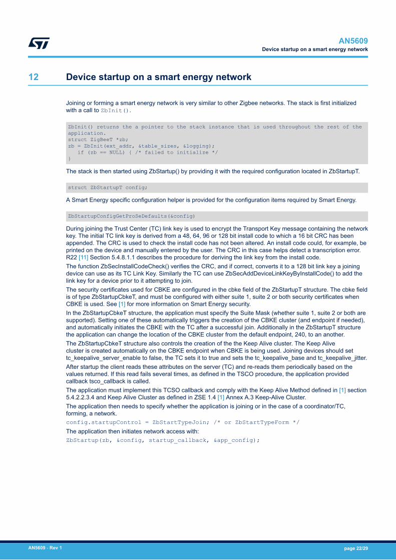
Joining or forming a smart energy network is very similar to other Zigbee networks. The stack is first initializedwith a call to ZbInit().
ZbInit() returns the a pointer to the stack instance that is used throughout the rest of the application.struct ZigBeeT *zb; zb = ZbInit(ext_addr, &table_sizes, &logging); if (zb == NULL) { /* failed to initialize */ }
The stack is then started using ZbStartup() by providing it with the required configuration located in ZbStartupT.
struct ZbStartupT config;
A Smart Energy specific configuration helper is provided for the configuration items required by Smart Energy.
ZbStartupConfigGetProSeDefaults(&config)
During joining the Trust Center (TC) link key is used to encrypt the Transport Key message containing the networkkey. The initial TC link key is derived from a 48, 64, 96 or 128 bit install code to which a 16 bit CRC has beenappended. The CRC is used to check the install code has not been altered. An install code could, for example, beprinted on the device and manually entered by the user. The CRC in this case helps detect a transcription error.R22 [11] Section 5.4.8.1.1 describes the procedure for deriving the link key from the install code.The function ZbSecInstallCodeCheck() verifies the CRC, and if correct, converts it to a 128 bit link key a joiningdevice can use as its TC Link Key. Similarly the TC can use ZbSecAddDeviceLinkKeyByInstallCode() to add thelink key for a device prior to it attempting to join.The security certificates used for CBKE are configured in the cbke field of the ZbStartupT structure. The cbke fieldis of type ZbStartupCbkeT, and must be configured with either suite 1, suite 2 or both security certificates whenCBKE is used. See [1] for more information on Smart Energy security.In the ZbStartupCbkeT structure, the application must specify the Suite Mask (whether suite 1, suite 2 or both aresupported). Setting one of these automatically triggers the creation of the CBKE cluster (and endpoint if needed),and automatically initiates the CBKE with the TC after a successful join. Additionally in the ZbStartupT structurethe application can change the location of the CBKE cluster from the default endpoint, 240, to an another.The ZbStartupCbkeT structure also controls the creation of the the Keep Alive cluster. The Keep Alivecluster is created automatically on the CBKE endpoint when CBKE is being used. Joining devices should settc_keepalive_server_enable to false, the TC sets it to true and sets the tc_keepalive_base and tc_keepalive_jitter.After startup the client reads these attributes on the server (TC) and re-reads them periodically based on thevalues returned. If this read fails several times, as defined in the TSCO procedure, the application providedcallback tsco_callback is called.The application must implement this TCSO callback and comply with the Keep Alive Method defined in [1] section5.4.2.2.3.4 and Keep Alive Cluster as defined in ZSE 1.4 [1] Annex A.3 Keep-Alive Cluster.The application then needs to specify whether the application is joining or in the case of a coordinator/TC,forming, a network.config.startupControl = ZbStartTypeJoin; /* or ZbStartTypeForm */The application then initiates network access with:ZbStartup(zb, &config, startup_callback, &app_config);
AN5609Device startup on a smart energy network
AN5609 - Rev 1 page 22/29
13 Back-haul network certification
Back-haul networks exist entirely outside the scope of the Zigbee interface.While the use of a back-haul network is common, the nature of the network and the regulatory environmentsurrounding it depends entirely on jurisdiction.In the UK where SMETS-II and the GBCS are mandated, Smart DCC has produced a test tool GFI (GIT ForIndustry [note this GIT is not related to the version control system] — GIT actually stands for GBCS InterfaceTool). This tool is located at: https://www.smartdcc.co.uk/products-services/gfi/ .Smart DCC does conduct testing on ESME, GSME, IHD, PPMID, CAD and HCALCS devices. DCC has a TestLab for devices and test scenarios are run through. The extent to which the GFI tool and/or real devices in the labare used is presently unknown. There is more information in the above link.In addition to this formal testing, device makers must also submit a Commercial Product Assurance (CPA)Document, which is a declaration of conformity generated by the device maker and submitted as part of theapproval process.More information about the CPA is located at: https://www.ncsc.gov.uk/information/commercial-product-assurancecpaIn addition to any other considerations mandated by the CPA, it also requires documented MISRA compliance.
AN5609Back-haul network certification
AN5609 - Rev 1 page 23/29
Revision history
Table 3. Document revision history
Date Revision Changes
17‑May‑2021 1 Initial release.
AN5609
AN5609 - Rev 1 page 24/29
Contents
1 General information . . . . . . . . . . . . . . . . . . . . . . . . . . . . . . . . . . . . . . . . . . . . . . . . . . . . . . . . . . . . . . .2
1.1 Acronyms and definitions . . . . . . . . . . . . . . . . . . . . . . . . . . . . . . . . . . . . . . . . . . . . . . . . . . . . . . . . 2
1.2 Reference documents. . . . . . . . . . . . . . . . . . . . . . . . . . . . . . . . . . . . . . . . . . . . . . . . . . . . . . . . . . . 2
1.2.1 Smart energy 1.4 . . . . . . . . . . . . . . . . . . . . . . . . . . . . . . . . . . . . . . . . . . . . . . . . . . . . . . . . 2
1.2.2 Smart energy 1.1b . . . . . . . . . . . . . . . . . . . . . . . . . . . . . . . . . . . . . . . . . . . . . . . . . . . . . . . 3
1.2.3 Zigbee PRO R22 - 2017 . . . . . . . . . . . . . . . . . . . . . . . . . . . . . . . . . . . . . . . . . . . . . . . . . . . 3
1.2.4 ZCL. . . . . . . . . . . . . . . . . . . . . . . . . . . . . . . . . . . . . . . . . . . . . . . . . . . . . . . . . . . . . . . . . . . 3
1.2.5 OTA. . . . . . . . . . . . . . . . . . . . . . . . . . . . . . . . . . . . . . . . . . . . . . . . . . . . . . . . . . . . . . . . . . . 3
1.2.6 Relationship between smart energy and other Zigbee® specifications . . . . . . . . . . . . . . . . 3
2 Smart energy overview . . . . . . . . . . . . . . . . . . . . . . . . . . . . . . . . . . . . . . . . . . . . . . . . . . . . . . . . . . . .4
3 Smart energy regulatory environment . . . . . . . . . . . . . . . . . . . . . . . . . . . . . . . . . . . . . . . . . . . . . .6
4 2.4 GHz and sub-GHz operation . . . . . . . . . . . . . . . . . . . . . . . . . . . . . . . . . . . . . . . . . . . . . . . . . . . .7
4.1 Duty cycle monitoring . . . . . . . . . . . . . . . . . . . . . . . . . . . . . . . . . . . . . . . . . . . . . . . . . . . . . . . . . . . 7
4.2 Listen before talk (LBT) . . . . . . . . . . . . . . . . . . . . . . . . . . . . . . . . . . . . . . . . . . . . . . . . . . . . . . . . . 7
4.3 Adaptive frequency agility (AFA) . . . . . . . . . . . . . . . . . . . . . . . . . . . . . . . . . . . . . . . . . . . . . . . . . . 7
5 Trust center swap out (TSCO). . . . . . . . . . . . . . . . . . . . . . . . . . . . . . . . . . . . . . . . . . . . . . . . . . . . . .9
6 Building smart energy applications using ZSDK cluster templates. . . . . . . . . . . . . . . . .10
6.1 Smart Energy device types . . . . . . . . . . . . . . . . . . . . . . . . . . . . . . . . . . . . . . . . . . . . . . . . . . . . . 10
6.2 Overview of Smart Energy clusters. . . . . . . . . . . . . . . . . . . . . . . . . . . . . . . . . . . . . . . . . . . . . . . 10
7 SE mandatory and optional clusters . . . . . . . . . . . . . . . . . . . . . . . . . . . . . . . . . . . . . . . . . . . . . .12
8 General clusters which do not require link key security . . . . . . . . . . . . . . . . . . . . . . . . . . .13
8.1 Basic cluster. . . . . . . . . . . . . . . . . . . . . . . . . . . . . . . . . . . . . . . . . . . . . . . . . . . . . . . . . . . . . . . . . . 13
8.2 Certificate based key establishment (CBKE) cluster. . . . . . . . . . . . . . . . . . . . . . . . . . . . . . . . . 13
8.3 Identify cluster . . . . . . . . . . . . . . . . . . . . . . . . . . . . . . . . . . . . . . . . . . . . . . . . . . . . . . . . . . . . . . . . 13
8.4 Alarms cluster . . . . . . . . . . . . . . . . . . . . . . . . . . . . . . . . . . . . . . . . . . . . . . . . . . . . . . . . . . . . . . . . 13
8.5 Power configuration . . . . . . . . . . . . . . . . . . . . . . . . . . . . . . . . . . . . . . . . . . . . . . . . . . . . . . . . . . . 13
9 General clusters which do require link key security . . . . . . . . . . . . . . . . . . . . . . . . . . . . . . .14
9.1 Time cluster . . . . . . . . . . . . . . . . . . . . . . . . . . . . . . . . . . . . . . . . . . . . . . . . . . . . . . . . . . . . . . . . . . 14
9.2 Commissioning cluster . . . . . . . . . . . . . . . . . . . . . . . . . . . . . . . . . . . . . . . . . . . . . . . . . . . . . . . . . 14
AN5609Contents
AN5609 - Rev 1 page 25/29
9.3 Keep-Alive cluster . . . . . . . . . . . . . . . . . . . . . . . . . . . . . . . . . . . . . . . . . . . . . . . . . . . . . . . . . . . . . 14
10 Smart Energy clusters . . . . . . . . . . . . . . . . . . . . . . . . . . . . . . . . . . . . . . . . . . . . . . . . . . . . . . . . . . . .15
10.1 Demand response load control cluster . . . . . . . . . . . . . . . . . . . . . . . . . . . . . . . . . . . . . . . . . . . . 15
10.1.1 DRLC server cluster on the ESI . . . . . . . . . . . . . . . . . . . . . . . . . . . . . . . . . . . . . . . . . . . . 15
10.2 Messaging cluster . . . . . . . . . . . . . . . . . . . . . . . . . . . . . . . . . . . . . . . . . . . . . . . . . . . . . . . . . . . . . 16
10.3 Keep-Alive . . . . . . . . . . . . . . . . . . . . . . . . . . . . . . . . . . . . . . . . . . . . . . . . . . . . . . . . . . . . . . . . . . . 17
10.4 Metering cluster . . . . . . . . . . . . . . . . . . . . . . . . . . . . . . . . . . . . . . . . . . . . . . . . . . . . . . . . . . . . . . . 17
10.4.1 Metering cluster attribute formatting . . . . . . . . . . . . . . . . . . . . . . . . . . . . . . . . . . . . . . . . . 17
10.4.2 Metering cluster alarms. . . . . . . . . . . . . . . . . . . . . . . . . . . . . . . . . . . . . . . . . . . . . . . . . . . 18
10.4.3 Metering cluster and Fast Polling . . . . . . . . . . . . . . . . . . . . . . . . . . . . . . . . . . . . . . . . . . . 18
10.4.4 Metering cluster profiles . . . . . . . . . . . . . . . . . . . . . . . . . . . . . . . . . . . . . . . . . . . . . . . . . . 18
10.4.5 Metering cluster mirroring . . . . . . . . . . . . . . . . . . . . . . . . . . . . . . . . . . . . . . . . . . . . . . . . . 18
10.5 Price cluster . . . . . . . . . . . . . . . . . . . . . . . . . . . . . . . . . . . . . . . . . . . . . . . . . . . . . . . . . . . . . . . . . . 19
10.5.1 ESI pricing server . . . . . . . . . . . . . . . . . . . . . . . . . . . . . . . . . . . . . . . . . . . . . . . . . . . . . . . 19
10.6 Tunneling cluster . . . . . . . . . . . . . . . . . . . . . . . . . . . . . . . . . . . . . . . . . . . . . . . . . . . . . . . . . . . . . . 20
11 Partner Link Key. . . . . . . . . . . . . . . . . . . . . . . . . . . . . . . . . . . . . . . . . . . . . . . . . . . . . . . . . . . . . . . . . .21
12 Device startup on a smart energy network . . . . . . . . . . . . . . . . . . . . . . . . . . . . . . . . . . . . . . . .22
13 Back-haul network certification . . . . . . . . . . . . . . . . . . . . . . . . . . . . . . . . . . . . . . . . . . . . . . . . . . .23
Revision history . . . . . . . . . . . . . . . . . . . . . . . . . . . . . . . . . . . . . . . . . . . . . . . . . . . . . . . . . . . . . . . . . . . . . . .24
Contents . . . . . . . . . . . . . . . . . . . . . . . . . . . . . . . . . . . . . . . . . . . . . . . . . . . . . . . . . . . . . . . . . . . . . . . . . . . . . .25
List of tables . . . . . . . . . . . . . . . . . . . . . . . . . . . . . . . . . . . . . . . . . . . . . . . . . . . . . . . . . . . . . . . . . . . . . . . . . .27
List of figures. . . . . . . . . . . . . . . . . . . . . . . . . . . . . . . . . . . . . . . . . . . . . . . . . . . . . . . . . . . . . . . . . . . . . . . . . .28
AN5609Contents
AN5609 - Rev 1 page 26/29
List of tablesTable 1. Acronyms and definitions . . . . . . . . . . . . . . . . . . . . . . . . . . . . . . . . . . . . . . . . . . . . . . . . . . . . . . . . . . . . . . 2Table 2. Clusters used on a typical SE application . . . . . . . . . . . . . . . . . . . . . . . . . . . . . . . . . . . . . . . . . . . . . . . . . . 12Table 3. Document revision history . . . . . . . . . . . . . . . . . . . . . . . . . . . . . . . . . . . . . . . . . . . . . . . . . . . . . . . . . . . . . 24
AN5609List of tables
AN5609 - Rev 1 page 27/29
List of figuresFigure 1. Home Area Network . . . . . . . . . . . . . . . . . . . . . . . . . . . . . . . . . . . . . . . . . . . . . . . . . . . . . . . . . . . . . . . . 5
AN5609List of figures
AN5609 - Rev 1 page 28/29

IMPORTANT NOTICE – PLEASE READ CAREFULLY
STMicroelectronics NV and its subsidiaries (“ST”) reserve the right to make changes, corrections, enhancements, modifications, and improvements to STproducts and/or to this document at any time without notice. Purchasers should obtain the latest relevant information on ST products before placing orders. STproducts are sold pursuant to ST’s terms and conditions of sale in place at the time of order acknowledgement.
Purchasers are solely responsible for the choice, selection, and use of ST products and ST assumes no liability for application assistance or the design ofPurchasers’ products.
No license, express or implied, to any intellectual property right is granted by ST herein.
Resale of ST products with provisions different from the information set forth herein shall void any warranty granted by ST for such product.
ST and the ST logo are trademarks of ST. For additional information about ST trademarks, please refer to www.st.com/trademarks. All other product or servicenames are the property of their respective owners.
Information in this document supersedes and replaces information previously supplied in any prior versions of this document.
© 2021 STMicroelectronics – All rights reserved
AN5609
AN5609 - Rev 1 page 29/29


![ZigBee Stack Profile: Platform restrictions for compliant ...read.pudn.com/.../3...ZigBee-Feature-Set-Profile.pdf · 11 [R2] ZigBee 04140r05, ZigBee Protocol Stack Settable Values](https://img.pdfslide.us/doc/110x75/5f183a7d6417c0751a61665e/zigbee-stack-profile-platform-restrictions-for-compliant-readpudncom3zigbee-feature-set-.jpg)


![AT08550: ZigBee Attribute Reporting · ZigBee Attribute Reporting [APPLICATION NOTE] Atmel-42334A-ZigBee-Attribute-Reporting -ApplicationNote_012015 3 1 Overview The ZigBee Specification](https://img.pdfslide.us/doc/110x75/5f43d267b58b3c15740a0db6/at08550-zigbee-attribute-reporting-zigbee-attribute-reporting-application-note.jpg)