Embed Size (px)
Citation preview

CZECH TECHNICAL UNIVERSITY IN PRAGUE
DEPARTMENT OF MECHANICS, BIOMECHANICS AND MECHATRONICS
MECHANICAL ENGINEERING
Summary of Doctorate Dissertation
Developing Trabecular Structure
Eren Pehlivan, MSc
Supervisor: Prof. RnDr. Matej Daniel, Ph.D
Co-supervisor: Prof. Ing. Ján Džugan, Ph.D
Study programme: Mechanical Engineering
Study branch: Biomechanics
2019 Prague

i
Type of publication Summary of Ph.D. Dissertation
Title Developing trabecular structure
Author Eren Pehlivan, MSc
Supervisor Prof. RnDr. Matej Daniel, Ph.D.
Department of Mechanics, Biomechanics and
Mechatronics, Faculty of Mechanical Engineering,
Czech Technical University in Prague, Czech Republic
Co-supervisor Prof. Ing. Ján džugan, Ph.D.
Research and development
Director Member of the Board of Directors
Comtes fht a.s. Dobřany, Czech Republic
University Czech Technical University in Prague
Faculty Faculty of Mechanical Engineering
Department Department of Mechanics, Biomechanics and
Mechatronics
Address Technická 4, 166 07 Prague 6, Czech Republic
Number of page 34

ii
Contents
1. INTRODUCTION ..................................................................................................... 1
2. AIM OF THE WORK ................................................................................................ 2
3. METHOD ............................................................................................................... 3
3.1 MECHANICAL CHARACTERIZATION OF POROUS CONNECTORS .......................................................................... 3
3.2 MECHANICAL RESPONSE OF TITANIUM ALLOY POROUS SAMPLES WITH HIP AND SURFACE TREATMENT ................... 5
3.3 DYNAMIC RESPONSE OF POROUS STRUCTURE WITH POST TREATMENTS ............................................................ 7
3.4 NUMERIC AND ANALYTIC APPROACH FOR POROUS STRUCTURE ....................................................................... 8
4. RESULT ........................................................................................................................................... 12
4.1 POROUS CONNECTORS MECHANICAL RESPONSE ......................................................................................... 12
4.2 HIP AND SURFACE TREATMENT EFFECT ON POROUS STRUCTURE ................................................................... 15
4.3 ANALYTIC AND NUMERICAL APPROACH FOR POROUS STRUCTURE DEVELOPMENT .............................................. 19
5. DISCUSSION .................................................................................................................................. 21
5.1 SINGLE STRUT SIZE AND BUILDING ORIENTATION EFFECT ON MECHANICAL PROPERTIES ....................................... 21
5.2 POST TREATMENT EFFECT ON POROUS STRUCTURE ..................................................................................... 23
5.3 MECHANICAL RESPONSE OF POROUS STRUCTURE UNDER DYNAMIC LOADING ................................................... 24
5.4 ANALYTIC AND NUMERICAL APPROACH FOR POROUS STRUCTURE .................................................................. 25
6. CONCLUSION ....................................................................................................... 26
7. BIBLIOGRAPHY .................................................................................................... 27
8. LIST OF AUTHOR PUBLICATIONS .......................................................................... 34

1
1. Introduction
Additive manufacturing (AM) of titanium alloys is rapidly becoming a global trend for
biomedical industry. Biocompatible titanium and its alloys are mostly used as an AM material
for joint and bone replacement. AM from biocompatible metal alloys has the potential to
revolutionize the design and production of joint replacements [1]. The AM process could
create custom shapes of implants adjusted for individual patient, and/or optimize implant’
surface [2]. The remarkable possibility of AM is in manufacturing porous structures resembling
the geometry of a trabecular bone. It was proposed that bone-like structure could increase
the longevity of joint replacement by reducing the stress-shield effect and by enhancing
osteointegration [3][4][5].
The porous structure could be considered as the three-dimensional mesh of interconnecting
struts [6]. The mechanical properties of the porous structure are given by the geometry of the
mesh and by the properties of individual struts [7][8]. It can further be adjusted by tuning
open-cell architecture, strut thickness (relative density) and choice of materials [9][10][8][11].
The variation in the properties of single struts is usually neglected. The unit cell intrinsically
consists of struts built at various angles and possibility of different thickness [12][13]. It was
shown that building orientation affects the mechanical properties of AM components. In
addition, the small elements produced by AM might exhibit a large variation in mechanical
properties [14].
Selective laser melting (SLM) is a widely used AM method for creating arbitrarily complex and
predictable porous 3D structures [15][16]. SLM forms an implant from titanium powder by
melting the powder layer by layer and forming the solid structure in the melted region. The
bulk titanium could contain internal pores as a result of SLM process. These internal defects
influence strength considerably. It was shown that hot isostatic pressing (HIP) can be used
effectively to reduce internal defects of AM metals. The effect of HIP is well documented for
solid structure, its potential advantage for porous structures has not been described in the
previous literature.
The SLM methods produce not only internal defects but gives also a very rough surface.
During the AM process, some powder particles are partly melted and remain loosely
connected at the surface. It was suggested that the released particles can have adverse long-
2
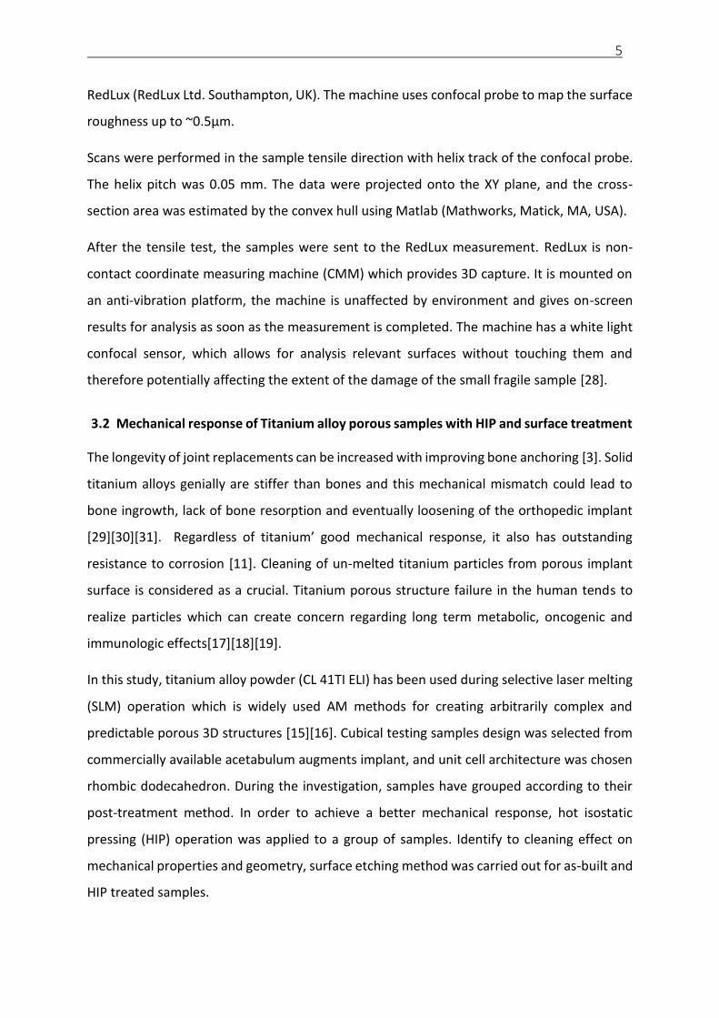
term metabolic, oncogenic and immunologic effects [17][18][19]. Loosely attached powder
could be removed from the surface of solid implant by polishing or machining. Cleaning of un-
melted titanium particles from porous implant surface is not straightforward but could be
considered as a crucial for further in-vivo application. In this study, dynamic compression and
quasi-static mechanical tests were carried out in order to (a) identify the effect of HIP
treatments and (b) determine the effect of chemical etching on mechanical properties in
porous samples.
Analytic and numerical approach help to improve understanding of the mathematical
background of cellular structure. The previous works mainly focused on tetrakaidecahedral
cellular structures since it is widely used in the automotive industry. In this study, rhombic
dodecahedron structure was investigated since the same structure was used for mechanical
tests. 2D and 3D analytic models were used to compare with numerical approach in order to
develop a representative model for complex porous components. The present study is
concerned with modelling and simulation of the mechanical behavior of regular open cell
porous structures by the finite element method. Mathematical model of this study also
illustrates that material data can play a vital role in calculating mechanical response cellular
architecture.
2. Aim of the work
Trabecular or porous structures are widely used in the biomedical industry in order to achieve
ideal bone integration. The current porous structures are stochastic in principle and used as
a surface coating that is based on their manufacturing using plasma spray. Additive
manufacturing (AM) is capable to deliver bulk porous structure with controlled geometry. The
porous structure consists of elements at the limit of AM accuracy that has not been studied
extensively so far. The purpose of this study is to evaluate mechanical properties of trabecular
metal structure created by using additive manufacturing technique for orthopedic
application. The aim of this study is to test the hypothesis that the AM cellular structure
mechanical properties are influenced by open-cell architecture, strut thickness, relative
density, and choice of materials.
Specific aims of the study is:

3
To determine the size effect of AM small samples on their mechanical properties
To quantify and explain the effect of post-treatment methods on mechanical
properties of AM porous structure
To assess the role of environmental conditions in the human body on the mechanical
behavior of the cellular structure.
To address problems above, hierarchical experimental and theoretical approaches reflecting
the porous material structure are introduced within this study.
3. Method
3.1 Mechanical characterization of porous connectors
The porous structure could be considered as the three-dimensional mesh of interconnecting
struts [6]. The mechanical property of the porous construct is given by the geometry of the
mesh and by the properties of individual struts and connecting elements [7][8]. In these
studies, the mechanical properties of the porous material are derived from the unit cell
[20][21]. The unit cell intrinsically consists of struts build at various angles and could have also
different thickness [12][13]. It was shown that building orientation affects the mechanical
properties of AM components [14]. The testing sample size corresponds to the strut size used
in porous joint replacement components, Figure 3.1.
a. Acetabulum metal augments surface with rhombic dodecahedron porous structure
b. Complex rhombic dodecahedron structure
c. rhombic dodecahedron unit cell
d. Single strut connector of the rhombic dodecahedron
e. Single strut connector test sample
Figure 3.1 Root of single strut application area [22]

4
The sample were fabricated from Concept laser CP-Ti Grade 2 powder consisting of particles
with size ranging from 45 to 100 𝜇𝑚 [23]. Chemical composition of raw material and the
mechanical properties data are valid for unalloyed CP-Ti according to ASTM F67, while it can
been expected that additively manufactured material might have higher yield strength than
reference material [24].
The computer-aided design package SolidWorks (Dassault Systemes SolidWorks Corp.,
Waltham MA) was used to design computer models of the plate tensile specimens. The
thickness of the samples was designed to be 0.5 mm while the width of the sample ranged
from 0.15 mm to 4.2 mm. The designed cross-sectional area has a shape of a rectangle with
area ranging from 0.07 mm2 to 2.10 mm2.
Additive manufacturing was performed by the Concept Laser the M2 cusing machine
(Concept Laser GmbH, Lichtenfels, Germany) that adopts selective laser sintering method.
Manufacturer’s recommendation was applied [25].
Two orientations of samples with respect to the building direction were chosen. ASTM
WK49229 [26] was used denoting the building direction as Z while the ground plane is
denoted as XY.
Tensile tests at room temperature were carried out under quasi-static loading conditions.
Miniaturized specimens were tested using a test method based on ASTM E8 [27]. Fixed cross-
head velocity was set at 0.2 mm/min. The test specimens’ cross-sectional area (So) was
measured prior and after the test using stereomicroscope in order to allow subsequent
evaluation of tensile test parameters such as yield stress (YS), ultimate tensile strength (UTS),
elastic modulus (E) and elongation after fracture (A). Tests were carried out by the small size
testing system with the load-cell capacity of 5kN. Longitudinal strain was measured by the
digital image correlation (DIC) system Sorbriety (Sobriety, Czech Republic) that was used in
2D set up as the virtual extensometer. The system was calibrated prior each batch. Stochastic
speckle pattern was applied to all tensile specimens by airbrush.
ZXY and YZX building orientation surfaces have been investigated with scanning electron
microscope (SEM) Tescan VEGA-3 LMU (Tescan, Czech Republic). Geometrical accuracy of
additive manufacturing was evaluated using optical 3D coordinate measuring machine
5
RedLux (RedLux Ltd. Southampton, UK). The machine uses confocal probe to map the surface
roughness up to ~0.5µm.
Scans were performed in the sample tensile direction with helix track of the confocal probe.
The helix pitch was 0.05 mm. The data were projected onto the XY plane, and the cross-
section area was estimated by the convex hull using Matlab (Mathworks, Matick, MA, USA).
After the tensile test, the samples were sent to the RedLux measurement. RedLux is non-
contact coordinate measuring machine (CMM) which provides 3D capture. It is mounted on
an anti-vibration platform, the machine is unaffected by environment and gives on-screen
results for analysis as soon as the measurement is completed. The machine has a white light
confocal sensor, which allows for analysis relevant surfaces without touching them and
therefore potentially affecting the extent of the damage of the small fragile sample [28].
3.2 Mechanical response of Titanium alloy porous samples with HIP and surface treatment
The longevity of joint replacements can be increased with improving bone anchoring [3]. Solid
titanium alloys genially are stiffer than bones and this mechanical mismatch could lead to
bone ingrowth, lack of bone resorption and eventually loosening of the orthopedic implant
[29][30][31]. Regardless of titanium’ good mechanical response, it also has outstanding
resistance to corrosion [11]. Cleaning of un-melted titanium particles from porous implant
surface is considered as a crucial. Titanium porous structure failure in the human tends to
realize particles which can create concern regarding long term metabolic, oncogenic and
immunologic effects[17][18][19].
In this study, titanium alloy powder (CL 41TI ELI) has been used during selective laser melting
(SLM) operation which is widely used AM methods for creating arbitrarily complex and
predictable porous 3D structures [15][16]. Cubical testing samples design was selected from
commercially available acetabulum augments implant, and unit cell architecture was chosen
rhombic dodecahedron. During the investigation, samples have grouped according to their
post-treatment method. In order to achieve a better mechanical response, hot isostatic
pressing (HIP) operation was applied to a group of samples. Identify to cleaning effect on
mechanical properties and geometry, surface etching method was carried out for as-built and
HIP treated samples.

6
The Samples were manufactured from Consept Laser titanium alloy grade 23 (CL 41TI ELI)
powder [32]. The computer-aided design package SolidWorks (Dassault Systemes SolidWorks
Corp., Waltham MA) and Materialise/Magics (Magics - Leuven, Belgium) software were used
to design computer models of cubical samples. Dimensions of cubical sample were set 6 mm,
and 2 mm rhombic dodecahedron open unit-cell was used, Figure 3.2. Relative density was
defined 20% due to strut thickness which was 0.3 mm. The rhombic dodecahedron unit cell
consists of 12 identical rhombic faces with 24 edges and 14 vertices [11].
Figure 3.2 Compression samples dimension [66]
M2 cusing machine (Concept Laser GmbH, Lichtenfels, Germany) that adopts selective laser
melting (SLM) method was used for additive manufacturing performing. SLM process was
carried out with manufacturer’s recommendation [25]. Furthermore, surface etching and hot
isostatic pressing (HIP) were applied to some groups of samples. The thickness of the
connector struts was evaluated from scanning electron microscope (SEM) Tescan VEGA-3
LMU (Tescan, Czech Republic) with ImageJ software. Hot isostatic pressing (HIP) was carried
out at Bodycote Bourgogne (Bodycote HIP Ltd.). Samples were divided into 6 groups according
to post-treatment method and each group contains 4 samples, Table 3.1.
Table 3.1 Sample description and group definition
Group code Name of the group
SNHHTNS Sample No Heat, HIP and surface treatment
SWHIT Sample with HIP treatment
SWS3T Sample with Surface treatment 3 min
SWS6T Sample with Surface treatment 6 min
SHITS3T Sample with HIP treatment with surface treatment 3 min
SHITS6T Sample with HIP treatment with surface treatment 6 min

7
Two types of geometrical measurement was done in order to identify geometrical accuracy
and effect of post-treatment. Connector strut thickness measurement was done in order to
identify the surface treatment effect on the connector diameters.
Mechanical compression test was carried out with MTS 858 Mini Bionix testing machine (MTS,
Eden Prairie, USA) with 5 KN load cell. The loading speed was set at a constant of 0.1 mm/
min, it aims to maintain a constant strain rate according to ASTM E9. The deformation was
measured with the linear variable differential transformer (LVDT) and elastic gradient was
calculated as the slope of the stress-strain curves between 30% and 70% of the plateau
strength according to ISO 13314). 0.2% offset method was used for determining the
compressive proof stress and maximum first strength was obtained from the diagram.
3.3 Dynamic response of porous structure with post treatments
Concept laser titanium grade 23 (CL 41TI ELI) has been used during selective laser melting
(SLM) [32]. The computer-aided design package SolidWorks (Dassault Systemes SolidWorks
Corp., Waltham MA) and Materialise/Magics (Magics - Leuven, Belgium) software were used
to design computer models of cubical samples. Cubical porous samples dimension was
adjusted 6 mm and 2 mm rhombic dodecahedron open regular unit cell was used.
Selective laser melting (SLM) M2 cusing machine (Concept Laser GmbH, Lichtenfels, Germany)
was used for AM process. SLM manufacturer’s recommendation was applied [25]. The
thickness of the connector struts was evaluated from scanning electron microscope (SEM)
Tescan VEGA-3 LMU (Tescan, Czech Republic) with ImageJ software. Hot isostatic pressing
(HIP) was carried out at Bodycote Bourgogne (Bodycote HIP Ltd.).
Table 3.2 Sample description and group definition
Group code Name of the group
B As-built
H HIP treatment
B3 Surface treatment 3 min
H3 HIP treatment with surface treatment 3 min
B6 Surface treatment 6 min
H6 HIP treatment with surface treatment 6 min

8
Samples were grouped in 6 groups according to post-treatment method. 54 samples were
manufactured for the impact test. 3 different environmental conditions were formed in order
to simulate in-vivo conditions.
Impact test was carried out in the air, water, and blood like material [33]. The impact tests
were performed in a drop test impact machine IMATEK-IM10 (Imatek Ltd., Old Knebworth,
UK) [34].
3.4 Numeric and analytic approach for porous structure
One of the well-known examples of honeycombs is hexagonal cell. The honeycombs
foundation is the idea of porosity structure in two dimension geometry. Therefore, it helps to
understand the simplified porosity structure [35]. It is considered, three dimensions cellular
structure would be defined as a foam shape which consists of interconnected networks like
honeycombs [36].
Figure 3.3 Unit honeycomb cell [37]
Theoretical calculation of elastic modulus in the plane;
𝐸𝑥
𝐸𝑠=
𝐸𝑦
𝐸𝑠=
4
√3(
𝑡
𝑙)
3
Ex* and EY* are elastic modulus in the x- and y-directions, respectively. The thickness to
length ratio, 𝑡/𝑙 is given as a function of the relative density ρ∗
ρ𝑠 by;
(𝑡
𝑙) =
√3
2(
𝜌∗
𝜌𝑠)
This equation is used by condition under 𝑡 𝑙⁄ < 0.2. Calculation can be only use small 𝑡 𝑙⁄
values. It was also calculated an analytical expression for the yield strength of a hexagonal
unit cell with elastic-perfectly plastic cell walls [38];

9
(𝑡
𝑙) < 3 (
𝜎𝑦𝑠
𝐸𝑠)
Plastic collapse occurs when the bending moment in the cell walls reaches the fully plastic
moment. Two moments are balanced, the plastic yield stress of the regular hexagon reduces
to;
𝜎𝑥
𝜎𝑠=
𝜎𝑦
𝜎𝑠=
2
3(
𝑡
𝑙)
2
In order to reach analytic calculation results, wall thickness, relative density, wall length
elastic modulus are defined as;
𝐸_𝑥/𝐸_𝑠 = 𝐸_𝑦/𝐸_𝑠 = 4/√3 (𝑡/𝑙)^3
𝜎_𝑥/𝜎_𝑠 = 𝜎_𝑦/𝜎_𝑠 = 2/3 (𝑡/𝑙)^2
In order to find elastic modulus components, x and y directions.
Wall thickness and length ratio was defined as 0.13 (𝑡 𝑙⁄ = 0.13). Relative density and elastic
modulus were chosen 0.15 and 1 respectively. Numeric calculations were carried out with
Abaqus (Hibbitt, Karlsson, & Sorensen, Inc., Pawtucket, RI) software.
Figure 3.4 Unit honeycomb cell deflection results in Abaqus [37]
Stress [x-direction]-------------------------------------- 𝜎𝑥 =𝐹𝑥
2𝑏𝑙𝑐𝑜𝑠𝜃
Strain [x-direction]-------------------------------------- 𝜀𝑥 =𝑈𝑥
2(𝑙 + 𝑙𝑠𝑖𝑛𝜃)
Stress, strain, and x-direction of elastic modulus components were calculated by using
reaction force and displacement. The first equation gives us a stress contribution of x-
direction and the second equation explain strain in the x-direction. Therefore, x-direction of
Young modulus can be calculated by using the conventional following equation;

10
𝐸𝑥 =𝜎𝑥
𝜀𝑥
3D porous structure analytic approach was designed according to actual cubical test samples.
Rhombic dodecahedron 2 mm unit-cell and 20% density was chosen. Strut connectors were
adjusted 0.3 mm thickness by defining according to density. The analytic calculation is also
calculated with the same condition with mechanical test in order to compare mechanical test
results.
Figure 3.5 Schematic of a regular rhombic dodecahedron structure. (A) Rhombic
dodecahedron unit cell comprises 12 identical rhombuses, (B) tessellated rhombic
dodecahedron cellular structure with 27unit cells, (C) unit
The unit cell of the rhombic dodecahedron consists of 12 identical rhombic faces with 24
edges and 14 vertices. Each face of a rhombic dodecahedron is a rhombus, with 2α= 70.53o
and 2ɵ= 109.47o. Strut shape is circular and thickness is 0.3 mm. For a 3-D rhombic
dodecahedron cellular structure of infinite size, each cell edge is shared by three adjacent unit
cells, so the effective relative density of a 3-D tessellated cellular structure denoted 𝜌 =
(3√3 2⁄ )𝜋(𝑟 𝑙⁄ )2. The cell edge material behaviour was taken as plastic, and comprised the
elastic modulus, 𝐸𝑠.
11
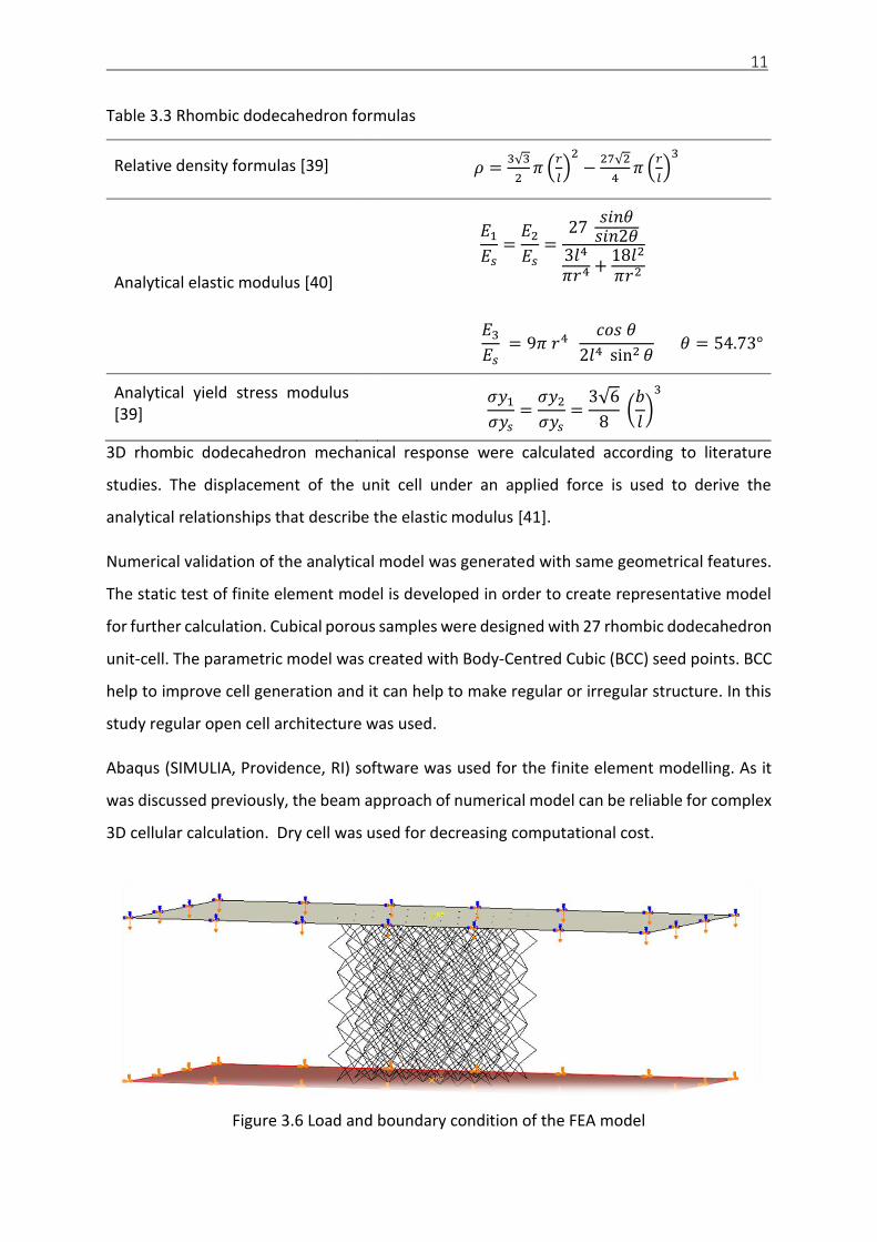
Table 3.3 Rhombic dodecahedron formulas
Relative density formulas [39] 𝜌 =3√3
2𝜋 (
𝑟
𝑙)
2
−27√2
4𝜋 (
𝑟
𝑙)
3
Analytical elastic modulus [40]
𝐸1
𝐸𝑠=
𝐸2
𝐸𝑠=
27 𝑠𝑖𝑛𝜃
𝑠𝑖𝑛2𝜃3𝑙4
𝜋𝑟4 +18𝑙2
𝜋𝑟2
𝐸3
𝐸𝑠 = 9𝜋 𝑟4
𝑐𝑜𝑠 𝜃
2𝑙4 sin2 𝜃 𝜃 = 54.73°
Analytical yield stress modulus [39]
𝜎𝑦1
𝜎𝑦𝑠=
𝜎𝑦2
𝜎𝑦𝑠=
3√6
8 (
𝑏
𝑙)
3
3D rhombic dodecahedron mechanical response were calculated according to literature
studies. The displacement of the unit cell under an applied force is used to derive the
analytical relationships that describe the elastic modulus [41].
Numerical validation of the analytical model was generated with same geometrical features.
The static test of finite element model is developed in order to create representative model
for further calculation. Cubical porous samples were designed with 27 rhombic dodecahedron
unit-cell. The parametric model was created with Body-Centred Cubic (BCC) seed points. BCC
help to improve cell generation and it can help to make regular or irregular structure. In this
study regular open cell architecture was used.
Abaqus (SIMULIA, Providence, RI) software was used for the finite element modelling. As it
was discussed previously, the beam approach of numerical model can be reliable for complex
3D cellular calculation. Dry cell was used for decreasing computational cost.
Figure 3.6 Load and boundary condition of the FEA model

12
2 parallel rigid blocks were designed to mimic compression test. Calculated and used material
properties for pure titanium; elastic modulus is 50 GPa, Poisson's Ratio is 0.3 and material
plastic region adjusted accordingly. Material data were chosen from previous single strut
study. Since it is a static analysis total displacement was set 2 mm in the z-direction. Boundary
conditions was applied as encastre (U1=U2=U3).
4. Result
4.1 Porous connectors mechanical response
The cross-sectional area of the samples estimated by optical surface scanning is approximately
9% lower than the cross-section area measured by laser scan micrometer or defined in CAD
model (mean 9.3%, stdev 14.5% and mean 8.6%, stdev 14.6%, respectively, Wilcoxon paired
test p<0.01 for both datasets, Figure 4.1). The CAD design and laser scan micrometers give
comparable values of cross-sectional area (mean difference 0.6%, stdev 0.7%, Wilcoxon paired
test p=0.16). The absolute relative differences between designed cross-section and optical
surface scanning were measured based on the cross-section range from 0% to 40% and the
higher values were found in smaller samples. The absolute values of difference in the cross-
sectional area between the designed and measured values range from -0.19 to 0.22 mm2
across all sizes of studied samples cross-sections. The observed discrepancies are caused by
the shape of the samples where the design and DIC measurements assume rectangular cross-
section. The real manufactured cross-section of small sample resembles ellipse.
Figure 4.1 Statistical of comparison the geometrical accuracy [22]

13
Table 4.1 Mechanical result of tensile test [22]
Elastic Gradient
Yield Strength Ultimate Tensile Strength
Elongation After Fracture
E (MPa) YS (MPa) UTS (MPa) A (%)
ZXY built orientation 0.70±0.27 613.94±139.29 676.46±145.89 10.59±10.17
YZX built orientation 0.68±0.24 405.29±142.84 469.88±144.63 9.84±5.42
The internal structure affects also material properties determined by the tensile test (Table
4.1). The ZXY build sample exhibits significantly higher yield strength and ultimate strength
than YZX samples. There is no significant difference in the elastic modulus and the elongation
among tested samples. However, the measured data indicate that mechanical properties
could depend also on the sample size. Therefore, a two-way analysis of covariance ANCOVA
was conducted to compare the main effects of the sample orientations and cross-sectional
areas and the interaction between the sample orientations and size of the cross-sectional
area on the yields strength. The main effect for sample orientation in the building chamber
yielded an F-ratio of F(1,62)=48.64, p<0.001 indicating the significant difference between ZXY
(mean 613 MPa and stdev 139 MPa) and YZX (mean 405 MPa and 143 MPa) oriented samples.
The main effect for the cross-sectional area yielded an F-ratio of F(1, 62) = 2.45, p=0.12,
indicating that the effect for the cross-sectional area was not significant. However, the
interaction effect was significant, F(1, 62)=22.96, p<0.001.
To further study this interaction, samples were divided into two groups according to their
cross-sectional area (So): (I) with a cross-section smaller than 1.5 mm2 and (II) represents
samples with a cross-sectional area larger than 1.5 mm2.

14
Figure 4.2 Samples in section I and II (So<1.5mm2) stress-strain results. The red lines
represent specimens built with ZXY orientation and green line represent YZX orientation
respectively [22]
The sample microstructure determines its mechanical behaviour. The sample build in ZXY
orientation has considerable higher yields strength than sample build in YZX orientation.
However, the internal defects conditions low elongation in sample build in ZXY orientation.
This behaviour was observed in samples with small cross-sectional area. Samples with higher
cross-sectional area, the yield strength is almost the same, while the elongation is higher in
ZXY built samples, Figure 4.2.
Figure 4.3 Section II (So>1.5mm2) samples stress-strain results. The red lines represent
specimens built in ZXY orientation and green lines represent YZX built orientation
respectively [22]

15
The ZXY samples have higher strength than YZX samples in small samples (group I), (Wilcox
test p<0.01, Figure 4.2) that is in agreement with results presented in Table 4.1. However,
these two groups also differ in elongation. The ZYX samples have almost brittle behaviour
with limited elongation. The behaviour changed for larger samples (group II, Figure 4.3),
where the yield strength is almost the same in the both ZXY and YZX group while the
elongation in ZYX samples is larger than in XYZ oriented samples.
The results for the yield strength are summarized in Figure 4.4. Our results indicate that the
orientation effect is crucial for small samplers (So<1.5 mm2) while it is less important if the
cross-sectional area is larger than 1.5 mm2.
Figure 4.4 Yield strength (YS) for small struts-like specimens with different cross-section and
building orientation. The group I and II are defined on the base of the cross-sectional area
(group I: So<1.5 mm2 and group II: 1.5 mm2<So). Red symbol and dash line show the result
of the sample with ZXY building orientation. Green square symbol and dotted line illustrate
the result of specimen build in YZX orientation [22]
4.2 HIP and surface treatment effect on porous structure
Single strut measurement was done and compare after the surface and HIP treatments. Cad
design of the connector strut thickness was 0.3mm however, AM samples without any
treatment had slightly bigger strut diameters due to the accuracy of the SLM. Surface etching
time would change the diameter of the connectors in the porous structure up to 14%.

16
Figure 4.5 SEM result of post-treatment effect on surface [22]
Figure 4.5 shows the surface etching effect on samples without any treatment and samples
with HIP treatment. It can be observed that surface etching can remove partly melted powder
on the struts and create a smoother surface. However, the process can make struts quite
thinner. Furthermore, struts can achieve clear beam form and homogenous shape after
etching. This achievement can provide consistent behaviour under compressive loading.
Table 4.2 Compression test mechanical result [22]
No Group name Elastic gradient (GPa)
Compressive proof Stress (MPa)
First maximum compressive strength (MPa)
1 SNHHTNS 1.76 ± 0.05 38.70± 0.63 56.87± 0.98
2 SWHIT 1.87 ± 0.05 38.13 ± 0.55 52.67 ± 2.92
3 SWS3T 1.31 ± 0.13 31.66 ± 1.66 44.84 ± 3.63
4 SWS6T 1.23 ± 0.08 30.11 ± 0.43 39.84 ± 2.16
5 SHITS3T 1.48 ± 0.11 31.50 ± 0.94 43.02 ± 4.19
6 SHITS6T 1.34 ± 0.06 28.49 ± 1.24 38.41 ± 1.86
Table 4.2 shows the mechanical result of compression test according to groups. It can be seen
that HIP process can deliver an enhanced elastic gradient due to decreasing internal defect
[42]. On the other hand, surface treatment can influence almost all mechanical parameters
since it tends to decrease strut thickness.

17
Elastic gradients were calculated by elastic loading and unloading according to ISO 13314
guidelines [43]. Samples with HIP treatment (SWHIT) achieved the better elastic modulus
value and it has 5.88% higher performance than as-built samples (SNHHTNS). Sample with HIP
and 6 minutes surface treatment (SHITS6T) reached the lowest level of compressive proof
stress with 28.49 ± 1.24 MPa. Surface treatment time did not effect on compressive proof
stress significantly. SHITS6T and SHITS3T samples had only 9.5% difference on the average. As-
built (SNHHTNS) achieved the highest first maximum compressive strength (56.87± 0.98 MPa).
HIP treatment can decrease the strength by 7.4%. First maximum compressive strength
comparison of samples with surface treatment (SWS3T) and samples with HIP plus surface
treatment (SHITS3T) are quite close with the result of 3.5%.
Figure 4.6 Comparison of yield strength of porous samples with post-treatment and theoretical calculation [22]
Figure 4.7Comparison of elastic modulus of porous samples with post-treatment and theoretical calculation [22]
18
Figure 4.6 and Figure 4.7 show that surface etching decrease the strut thickness which effect
on cross-sectional area and mechanical response. Yield strength trend follows the theoretical
calculation which means surface treatment does not affect the porous behaviour. Porous
structure dynamic behavior
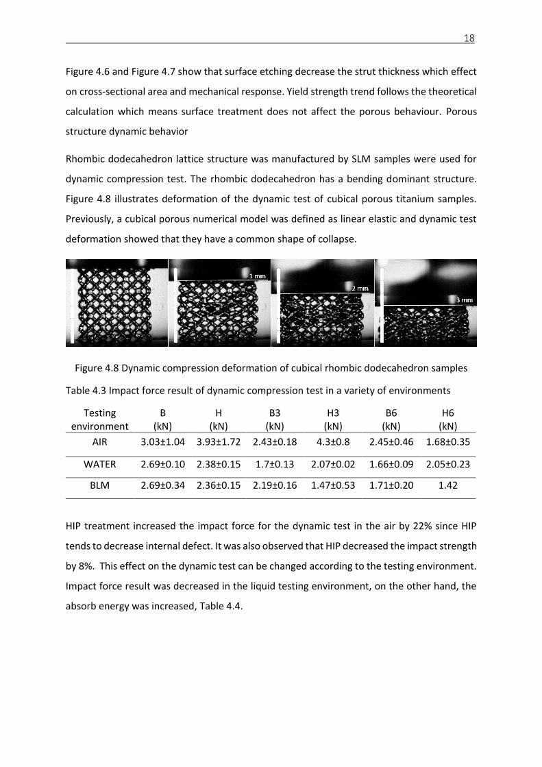
Rhombic dodecahedron lattice structure was manufactured by SLM samples were used for
dynamic compression test. The rhombic dodecahedron has a bending dominant structure.
Figure 4.8 illustrates deformation of the dynamic test of cubical porous titanium samples.
Previously, a cubical porous numerical model was defined as linear elastic and dynamic test
deformation showed that they have a common shape of collapse.
Figure 4.8 Dynamic compression deformation of cubical rhombic dodecahedron samples
Table 4.3 Impact force result of dynamic compression test in a variety of environments
Testing environment
B (kN)
H (kN)
B3 (kN)
H3 (kN)
B6 (kN)
H6 (kN)
AIR 3.03±1.04 3.93±1.72 2.43±0.18 4.3±0.8 2.45±0.46 1.68±0.35
WATER 2.69±0.10 2.38±0.15 1.7±0.13 2.07±0.02 1.66±0.09 2.05±0.23
BLM 2.69±0.34 2.36±0.15 2.19±0.16 1.47±0.53 1.71±0.20 1.42
HIP treatment increased the impact force for the dynamic test in the air by 22% since HIP
tends to decrease internal defect. It was also observed that HIP decreased the impact strength
by 8%. This effect on the dynamic test can be changed according to the testing environment.
Impact force result was decreased in the liquid testing environment, on the other hand, the
absorb energy was increased, Table 4.4.
19
Table 4.4 Impact strength result of dynamic compression test in variety of environments
Testing environment
B (J)
H (J)
B3 (J)
H3 (J)
B6 (J)
H6 (J)
AIR 0.6±0.17 0.55±0.21 0.49±0.08 0.71±0.20 0.44±0.09 0.42±0.31
WATER 0.99±0.06 0.76±0.08 0.36±0.07 0.44±0.13 0.44±0.10 0.30±0.05
BLM 0.84±0.26 0.67±0.27 0.79±0.06 0.32±0.21 0.45±0.11 0.39
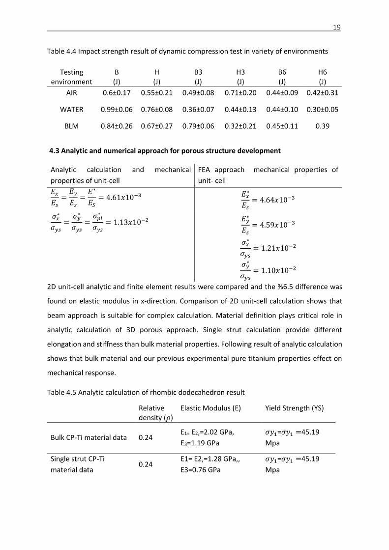
4.3 Analytic and numerical approach for porous structure development
Analytic calculation and mechanical
properties of unit-cell
FEA approach mechanical properties of
unit- cell
𝐸𝑥
𝐸𝑠=
𝐸𝑦
𝐸𝑠=
𝐸∗
𝐸𝑆= 4.61𝑥10−3 𝐸𝑥
∗
𝐸𝑠= 4.64𝑥10−3
𝜎𝑥∗
𝜎𝑦𝑠=
𝜎𝑦∗
𝜎𝑦𝑠=
𝜎𝑝𝑙∗
𝜎𝑦𝑠= 1.13𝑥10−2 𝐸𝑦
∗
𝐸𝑠= 4.59𝑥10−3
𝜎𝑥∗
𝜎𝑦𝑠= 1.21𝑥10−2
𝜎𝑦
∗
𝜎𝑦𝑠= 1.10𝑥10−2
2D unit-cell analytic and finite element results were compared and the %6.5 difference was
found on elastic modulus in x-direction. Comparison of 2D unit-cell calculation shows that
beam approach is suitable for complex calculation. Material definition plays critical role in
analytic calculation of 3D porous approach. Single strut calculation provide different
elongation and stiffness than bulk material properties. Following result of analytic calculation
shows that bulk material and our previous experimental pure titanium properties effect on
mechanical response.
Table 4.5 Analytic calculation of rhombic dodecahedron result
Relative density (𝜌)
Elastic Modulus (E) Yield Strength (YS)
Bulk CP-Ti material data 0.24 E1= E2,=2.02 GPa,
E3=1.19 GPa
𝜎𝑦1=𝜎𝑦1 =45.19
Mpa
Single strut CP-Ti
material data 0.24
E1= E2,=1.28 GPa,,
E3=0.76 GPa
𝜎𝑦1=𝜎𝑦1 =45.19
Mpa

20
On the other hand numerical calculation with material data we reached with our previous
experiments showed that plastic collapse can be occurred in the middle section of samples.
Figure 4.9 Stress-Strain diagram of FEA calculation
Reaction force was calculated from the reference point which was pre-defined. Stress
calculated from reaction force and cross-sectional area. The strain was calculated from
displacement, this method is similar to ISO 13314 (Mechanical testing of metals-ductility
testing-compression test for porous and cellular metals) [43]. Elastic modulus was calculated
as 0.55 GPa with the offset method from the stress-strain diagram, Figure 4.9. Stress-Strain
diagram divided into 3 sections.
Figure 4.10 Von Mises stress and deformation result of cellular model

21
5. Discussion
The porous structure is becoming trendy application in orthopedic implants [44]. Adjustable
geometrical freedom and low-density component can be provided with AM technology for
replacing damaged or unhealthy body parts [45]. Un-cemented joint implant surface
modification can help to increase bone anchoring therefore, AM can create arbitrarily
complex and predictable porous 3D structures[46][47].
Porous structure mechanical properties are important for medical application. It can decrease
stress shielding and increase osteointegration [48][49][50]. Therefore, porous structure
mechanical properties can be depended on unit-cell architecture, the material used,
connector strut thickness and relative density [51]. Optimizing mechanical response of
porous structure could be adjusted by strut thickness which changes relative density [52]. In
this research pores size adjusted to 0.6 mm which is an optimum value for bone ingrowth
[53]. Study of Mullen et al., 2008 shows that the size of the pores can affect bone anchoring
significantly [3].
5.1 Single strut size and building orientation effect on mechanical properties
The properties of individual segments of the truss-like porous structure affect its global
performance. In this study, it was shown that the building orientation of the struts and its size
influence its mechanical properties.
Building direction influences the surface geometry and the microstructure that has in turn
effect on mechanical properties. The AM process is primarily tuned to building in the Z-
direction, that was observed by finer microstructure and higher yield strength in ZXY (Vertical)
than in YZX (Horizontal) built specimens (Figure 4.2, Figure 4.3 and Figure 4.4). However, the
larger the cross-sectional area is, the smaller difference in yield strength is between the YZX
(Horizontal) and ZXY (Vertical) specimens, respectively (Figure 4.4). It has been also observed
a considerable amount of pores for ZXY (Vertical) specimens that conditioned low elongation,
regardless of the specimen cross-section size (Figure 4.2, Figure 4.3). The higher porosity in
ZXY (Vertical) samples was reported also in the previous studies, for review see Frasier et al.,
2014. The relatively higher porosity could be specific to used SLM setup, including powder,
scanning strategy and laser beam power. Slotwinski et al., 2014 showed that by changing the

22
manufacturing parameters, the porosity could be considerably influenced. However, the
study of Slotwinski et al., 2014 is based on large samples (a cross-sectional area more than
5000 mm2) and application of small samples used in this study (the cross-sectional area
around 1 mm2) may not be straightforward [54].
In addition to the yield strength, the size of the sample and its orientation have an impact on
material brittleness. For larger samples, the elongation for ZXY (Vertical) oriented samples is
higher than for YZX samples (Figure 4.3). Similar results were observed by Caulfield et al. 2006,
Wegner et al. 2012 and Witt, Negi et al. 2015 [55] [56][57]. The new finding in the present
study is, that elongation trend is reversed in small samples (Figure 4.2). We may hypothesize,
that this effect is process specific. If the sample is built in ZYX direction and the cross-sectional
area is small, the building area that laser spot melts is small. The amount of energy applied
during the SLM process is a function of laser spot size, scan radius, laser power, scan spacing,
and the laser scanner parameters [58]. The smaller the building area, the less optimal
hatching distance is achieved and the higher energy is accumulated in the overlapping laser
spots. The high melting energy could cause the brittleness of materials [59].
Within this study printed specimen that matched the size and shape of connectors of the
porous structure were investigated. However, the struts in the porous structure are always
printed in a pack with the whole structure. The presence of surrounding elements may
influence thermal gradients and mechanical properties. The most accurate testing will be to
isolate the individual element from the whole structure and measure its mechanical
properties. Considering the small size of individual elements, this would be technically
demanding. Based on the considerable difference between small sample build in a different
direction, we believe that the demonstrated method provides results that are applicable also
for complex mesh structures.
The advantage of truss structure based on simple shape interconnecting elements is, that the
properties of the whole construct could be derived from the unit cell. We have shown, that
in designing the optimal unit cell, the directions of individual elements should be taken into
account.
23
5.2 Post treatment effect on porous structure
Open-cell porous structure mechanical properties would affect bone interaction for
orthopedic applications [60]. SLM manufactured components universal performance can be
modified with post-treatment technique. HIP treatment was used for reducing internal
defects and stress realising which help to improve mechanical response. Surface treatment
was used for cleaning partly melted powder and preventing any toxicology outcomes in
orthopaedic use [61]. In this study, it is shown that regular porous structure mechanical
response was affected by surface and HIP treatment. The surface treatment by chemical
etching was used for cleaning partly melted powder, while the HIP treatment reduced internal
porosity [62][63][64].
Strut thickness and cross-sectional area can influence the mechanical performance of open-
cell porous structure[65]. During the compression loading, the consistent structure provides
uniform deformation which means that equivalent connector struts deal with a similar
loading. The perfect porous structure should provide stable mechanical properties with small
scattering between samples. Despite rough structure in as-build samples, they provide low
variation between the samples. The surface etching smooths surfaces but adds imperfections
in struts diameters that increase variations between the samples.
Level of surface treatment affects mechanical performance due to the fact that strut thickness
diameter is decreased by surface etching and this technique can be also used to create hybrid
porous component with different relative density [66]. As-built samples with 6-minute surface
treatment (SWS6T) has the lowest elastic modulus with 1.23 GPa respectively on the average.
Sample with both HIP and surface treatment has still higher elastic modules than as-built
samples with surface treatment. Compressive proof stress can be decreased by surface
etching. 6-minute surface treatment can reduce compressive proof stress by 25%. Sample
with HIP and 6-minute etching (SHITS6T) has the lowest value 28.49 MPa respectively on the
average.
Mechanical properties of porous samples with surface treatment and HIP can be a good
match with bone mechanical properties. Close mechanical properties of bone and porous
structure would decrease the stress shielding which can extend the lifetime of the implant
[67]. Surface etching also provides the excellent clean product which is crucial for biomedical
24
applications. Preventing the release of titanium particles from the implant is crucial for any
biomedical application, Heringa et al., 2018 study shows that titanium accumulation in the
human body can damage liver [68]. Woodman et al., 1984 research also shows ion release
from titanium-based implants effect and damage to human vital organs, namely liver, and
kidney [69]. It was suggested that separation of any un-melted powder from the porous
structure would lead to critical liver failure [70] and therefore surface treatment is highly
recommended for the commercial orthopedic product.
The results of the study indicate the effect of HIP and surface etching on mechanical
properties of porous samples. However, there are also other factors that should be
considered in a biomedical application. In this study, the investigation was carried out with
static compression test in the air however, porous structure in the human body is supposed
to deal with dynamic loading in blood-like material and body fluids environment. The fluids
and cells penetrate the structure and it may affect the corrosions of the implant [71]. The in-
vivo environment could increase the porous structure density and strength with
interpenetrating phase composites effect.
5.3 Mechanical response of porous structure under dynamic loading
Orthopaedic metal implant is surrounded by tissue fluid during the stay in the human body.
The in-vivo system contains water, complex organic compounds, dissolved oxygen, sodium,
chloride, bicarbonate, potassium, calcium, magnesium, phosphate, amino acids, proteins,
plasma, lymph, saliva [72]. Although porous samples were tested in the air in the literature,
commercial porous implants seldom bear with compressive load in the human body condition
and it can be either dynamic or quasi-static [116][117].
Previous studies focus dynamic test on aluminum foam and its energy absorption capability
since the automotive industry widely use foams for good impact force performance [75]. In
this experiment high speed (2m/s) impact test was carried out for impact force and energy
absorption performance of porous titanium alloy and applied post-treatment methods. The
same testing method was applied in blood like material (BLM) and water as well in order to
mimic human body condition. Dynamic impact force results were very similar for porous
sample in air, water, and blood like material. It is shown that an experiment can be carried
out in the air since impact force results in liquid environments can be tolerated. On the other
25
hand, the dynamic test stress-strain diagram shows that stress trend of porous structure in
the air very similar to test in water and blood like material. Current research shows that
mechanical tests can be carried out in the air for porous structures.
In addition, post-treatment method also has an effect on the mechanical performance of the
dynamic test. As it was mentioned in previous sections, surface etching tends to decrease
strut diameter and density as a result of that load bearing area is decreased. On the other
hand, behaviour of the porous structure with surface etching very similar to as-built samples.
Eroding sample can increase the pore size however, it still acts as an open-cell regular
structure.
5.4 Analytic and numerical approach for porous structure
Metallic open cell foam can be simplified as honeycombs for the 2D approach. Man-made
honeycombs can be seen in different industries. It can be found in nature where structures
have to deal with a different type of loading. Understanding the mechanical properties of
cellular solids can lead to improved materials design and performance. Open cell 2D
geometrical model was developed for analytic and numerical approach according to Gibson
and Ashby et. Al., 1997 [76] research. Elastic modulus and yield strength compared for unit
cell development for both analytic and numerical approach. Finite element analysis result for
elastic gradient was calculated in x- and y-direction. It was expected that Ex and Ey have to
be equal. In our calculation, there was 0.4% difference occurred. This is still satisfied result
to carry out 2D complex numerical calculation.
Babaee et. al., 2012 [77] shows that bulk material definition was used widely for the analytic
approach of struts mechanical properties. Our previous studies show that AM strut size and
orientation has an influence on mechanical properties significantly.
Analytic investigation and mechanical test of elastic modulus difference is 28%. Babaee et.
al., 2012 used bulk material properties in his calculation. However, powder type also can
change the elastic module. Another effect is that SLM machine accuracy, the analytic
calculation was planned for designed diameters with smooth connectors however, in printed
samples connectors slightly bigger and contains surface roughness. It may also change the
cross-sectional area and load bearing diameter.

26
Finite element models of both unit cell and tessellated cellular structures was developed and
used them to establish the validity of the analytical models. The elastic properties and yield
strength of the cellular structure were calculated from the force-displacement response of
the structure in each basic loading direction. The effective elastic modulus is the initial slope
of the response.
Elastic modulus of analytic calculation 57% difference than numerical calculation. Elasticity
and plasticity data were used from our previous study during the calculation. This difference
can be caused by the mathematical model contact accuracy which can be improved.
Deformation behaviour and collapse area are quite similar to mechanical testing, there is still
75% elastic modules difference remaining.
The mathematical model is developed and executed according to the same procedure of
mechanical test and analytic calculation. However, material data input plays a crucial role
during the calculation. Single strut mechanical properties were used for finite element
approach, result present that single porous structure mechanical behaviour quite
homogenous even though single struts mechanical properties are depending on building
orientation and their size.
6. Conclusion
Additive manufacturing (AM) does not only provide design freedoms or low-density
components, but it also helps to develop regular porous surface. AM porous structure
mechanical properties are influenced by manufacturing set-up, material, mesh architecture
and post treatments. Improving mechanical properties of AM porous surface of orthopedic
implant can increase bone integration and decrease implant loosening. In this study, the
mechanical response of porous structure was investigated intensively with the approach of
mesh architecture, post-treatment methods, and material consideration.
Connectors or struts are core elements of the open cell porous structure and they have a
different orientation in the cellular architecture. It has been experimentally shown in this
study, single strut properties were affected by the size and building orientation. The building
orientation direction effect is much less pronounced in larger samples [78]. Single strut
mechanical properties have been used for analytic and numerical calculation since previous

27
studies were designed by using bulk material data. We can conclude that material properties
definition plays a vital role in analytical and numerical calculation approach. Predicting the
mechanical properties of porous structure has been challenging since strut material definition
can be decisive. Quasi-static tests showed that mechanical responses of porous samples
manufactured from two different suppliers had different results even though the same pure
titanium powder were used.
In this research, conventional and new post-treatment methods have been used for
improving porous structure functional properties for biomedical application. Surface etching
decreases the strut diameter dramatically. On the other hand, it helps to prevent porous
structure struts together under the compressive deformation. This feature can be enchanted
with HIP treatment as well. Although compromising the strength of porous structure is
inevitable but it is still suitable for orthopedic biomedical applications [79].
Porous structure dynamic test was carried out in air, water, and blood like material since
titanium cellular structure frequently interacts with body fluid. We show that dynamic test
result of porous structure in the air was very similar to water and blood like material
environment. It shows that future mechanical test can be carried out in air conditions.
To conclude, the building orientation and geometrical accuracy of AM are one of the
parameters that should be considered the design of the complex truss porous structures. The
surface etching is a suitable method for post-processing of the porous structure [79]. In this
study, we have also shown that HIP treatment is not significantly effective for porous
structure mechanical properties.
7. Bibliography
[1] WANG, Xiaojian, Shanqing XU, Shiwei ZHOU, Wei XU, Martin LEARY, Peter CHOONG, M. QIAN, Milan BRANDT a Yi Min XIE. Topological design and additive manufacturing of porous metals for bone scaffolds and orthopaedic implants: A review. Biomaterials [online]. 2016, 83, 127–141. ISSN 18785905. Dostupné z: doi:10.1016/j.biomaterials.2016.01.012
[2] HAGEDORN, Y. Laser additive manufacturing of ceramic components. In: Laser Additive Manufacturing [online]. B.m.: Elsevier, 2017, s. 163–180. ISBN 9780081004340. Dostupné z: doi:10.1016/B978-0-08-100433-3.00006-3
[3] MULLEN, Lewis, Robin C. STAMP, Wesley K. BROOKS, Eric JONES a Christopher J. SUTCLIFFE. Selective laser melting: A regular unit cell approach for the manufacture of

28
porous, titanium, bone in-growth constructs, suitable for orthopedic applications. Journal of Biomedical Materials Research - Part B Applied Biomaterials [online]. 2009, 89(2), 325–334. ISSN 15524973. Dostupné z: doi:10.1002/jbm.b.31219
[4] A.CHAMAY a P.TSCHANTZ. Mechanical influences in bone remodeling. Experimental research on Wolff’s law. Journal of Biomechanics [online]. 1972, 5(2), 173–180. ISSN 00219290. Dostupné z: doi:10.1016/0021-9290(72)90053-X
[5] BIGERELLE, M. a K. ANSELME. A kinetic approach to osteoblast adhesion on biomaterial surface. Journal of Biomedical Materials Research - Part A [online]. 2005, 75(3), 530–540. ISSN 15493296. Dostupné z: doi:10.1002/jbm.a.30473
[6] HOLLISTER, S J. Porous scaffold design for tissue engineering. Nature Materials [online]. 2005, 4(7), 518–524. ISSN 1476-1122. Dostupné z: doi:10.1038/nmat1421
[7] BOMBAČ, David, Miha BROJAN, Peter FAJFAR, Franc KOSEL a Rado TURK. Review of materials in medical applications. RMZ – Materials and Geoenvironment [online]. 2007, 54(54), 471–499. Dostupné z: http://www.rmz-mg.com/letniki/rmz54/RMZ54_0471-0499.pdf
[8] ELIAS, C. N., J. H C LIMA, R. VALIEV a M. A. MEYERS. Biomedical applications of titanium and its alloys. Jom [online]. 2008, 60(3), 46–49. ISSN 10474838. Dostupné z: doi:10.1007/s11837-008-0031-1
[9] WIEDING, Jan, Anika JONITZ a Rainer BADER. The effect of structural design on mechanical properties and cellular response of additive manufactured titanium scaffolds. Materials [online]. 2012, 5(8), 1336–1347. ISSN 19961944. Dostupné z: doi:10.3390/ma5081336
[10] DO, Dang Khoa a Peifeng LI. The effect of laser energy input on the microstructure , physical and mechanical properties of Ti-6Al-4V alloys by selective laser melting [online]. 2016, 2759(March). Dostupné z: doi:10.1080/17452759.2016.1142215
[11] OKAZAKI, Yoshimitsu, Yoshimasa ITO, Kenj KYO a Tetsuya TATEISHI. Corrosion resistance and corrosion fatigue strength of new titanium alloys for medical implants without V and Al. Materials Science and Engineering A [online]. 1996, 213(1–2), 138–147. ISSN 09215093. Dostupné z: doi:10.1016/0921-5093(96)10247-1
[12] VAN BAEL, S., Y. C. CHAI, S. TRUSCELLO, M. MOESEN, G. KERCKHOFS, H. VAN OOSTERWYCK, J. P. KRUTH a J. SCHROOTEN. The effect of pore geometry on the in vitro biological behavior of human periosteum-derived cells seeded on selective laser-melted Ti6Al4V bone scaffolds. Acta Biomaterialia [online]. 2012, 8(7), 2824–2834. ISSN 17427061. Dostupné z: doi:10.1016/j.actbio.2012.04.001
[13] ZADPOOR, Amir A. Bone tissue regeneration: The role of scaffold geometry. Biomaterials Science [online]. 2015, 3(2), 231–245. ISSN 20474849. Dostupné z: doi:10.1039/c4bm00291a
[14] DZUGAN, J., M. SEIFI, R. PROCHAZKA, M. RUND, P. PODANY, P. KONOPIK a J. J. LEWANDOWSKI. Effects of thickness and orientation on the small scale fracture behaviour of additively manufactured Ti-6Al-4V. Materials Characterization [online]. 2018, 143(February), 94–109. ISSN 10445803. Dostupné z: doi:10.1016/j.matchar.2018.04.003
[15] ATTAR, H, M CALIN, L C ZHANG, S SCUDINO a J ECKERT. Materials Science & Engineering A Manufacture by selective laser melting and mechanical behavior of commercially pure titanium. Materials Science & Engineering A [online]. 2014, 593, 170–177. ISSN 0921-5093. Dostupné z: doi:10.1016/j.msea.2013.11.038
[16] SERCOMBE, T B, X LI, T B SERCOMBE a X LI. Selective laser melting of aluminium and

29
aluminium metal matrix composites : review Selective laser melting of aluminium and aluminium metal matrix composites : review [online]. 2016, 7857(May). Dostupné z: doi:10.1179/1753555715Y.0000000078
[17] MOMBELLI, Andrea, Dena HASHIM a Norbert CIONCA. What is the impact of titanium particles and biocorrosion on implant survival and complications ? A critical review [online]. 2018, 29(March), 37–53. Dostupné z: doi:10.1111/clr.13305
[18] JOSEF, Hlinka, Kvíčala MIROSLAV a Lasek STANISLAV. CORROSION PROPERTIES OF POROUS TITANIUM SINTERES WITH SODIUM CHLORIDE. In: 24th International Conference on Metallurgy and Materials 2015 Brno, Czech Republic, EU. 2015, s. 3–8.
[19] FRISKEN, K W, G W DANDIE, S LUGOWSKI a G JORDAN. A study of titanium release into body organs following the insertion of single threaded screw implants into the mandibles of sheep. Australian Dental Journal. 2002, (3), 214–217.
[20] LEICHT, Alexander; a Elon Oskar WANNBERG. Analyzing the Mechanical Behavior of Additive Manufactured Ti-6Al-4V Using Digital Image Correlation Analyzing the Mechanical Behavior of Additive Manufactured Ti-6Al-4V Using Digital Image Correlation. B.m., 2015. CHALMERS UNIVERSITY OF TECHNOLOGY.
[21] BOBYN, J. D., G. J. STACKPOOL, S. A. HACKING, M. TANZER a J. J. KRYGIER. Characteristics of bone ingrowth and interface mechanics of a new porous tantalum biomaterial. The Journal of Bone and Joint Surgery [online]. 1999, 81(5), 907–914. ISSN 00000000. Dostupné z: doi:10.1302/0301-620X.81B5.9283
[22] E.PEHLIVAN, M. ROUDNICKA, J.DZUGAN, V. KRÁLÍK, V.DALIBOR, M.SEIFI, J. LEWADOWSKID a M. DANIEL. Effect of build orientation and geometry on the mechanical response of tiny wire samples manufactured by selective laser melting Eren Pehlivan. Additive Manufacturing(In-Reviewing). 2018, 1–21.
[23] CONCEPT LASER. CL 42TI Commercially Pure Titanium-Material data [online]. nedatováno. Dostupné z: https://www.ge.com/additive/sites/default/files/2018-12/CLMAT_42Ti_DS_EN_US_2_v1.pdf
[24] VRANCKEN, Bey, Lore THIJS, Jean Pierre KRUTH a Jan VAN HUMBEECK. Heat treatment of Ti6Al4V produced by Selective Laser Melting: Microstructure and mechanical properties. Journal of Alloys and Compounds [online]. 2012, 541, 177–185. ISSN 09258388. Dostupné z: doi:10.1016/j.jallcom.2012.07.022
[25] TER HAAR, Gerrit M. a Thorsten H. BECKER. Selective laser melting produced Ti-6Al-4V: Post-process heat treatments to achieve superior tensile properties. Materials [online]. 2018, 11(1). ISSN 19961944. Dostupné z: doi:10.3390/ma11010146
[26] ASTM WK49229. Standard Guide for Orientation and Location Dependence Mechanical Properties for Metal Additive Manufacturing. 2017
[27] ASTM E8-Standard Test Methods for Tension Testing of Metallic Materials. ASTM International [online]. 2012, 946, 133–140. ISSN 16130073. Dostupné z: doi:10.1520/E0008_E0008M-13A
[28] REDLUX. Case Study : Rush University Medical Center Figuring Out Why Artificial Joints Fail [online]. 2016. Dostupné z: https://secure.toolkitfiles.co.uk/clients/19010/sitedata/PDFs/Reference-Rush-University-20170503.pdf
[29] NIINOMI, Mitsuo. Mechanical properties of biomedical titanium alloys. Materials Science and Engineering: A [online]. 2002, 243(1–2), 231–236. ISSN 09215093. Dostupné z: doi:10.1016/s0921-5093(97)00806-x
[30] ENGH, C A, J D BOBYN a A H GLASSMAN. Porous Coated Hip Replacement - Factors

30
Governing Bone In-growth, Stress Shielding and Clinical Results. 1987, 69(1). [31] NAGELS, Jochem, Mariëlle STOKDIJK a Piet M ROZING. Stress shielding and bone
resorption in shoulder arthroplasty. Journal of Shoulder and Elbow Surgery [online]. 2003, 12(1), 35–39. ISSN 10582746. Dostupné z: doi:10.1067/mse.2003.22
[32] CONCEPTLASER. Titanium alloy grade 23 CL 41TI ELI [online]. nedatováno. Dostupné z: https://www.ge.com/additive/sites/default/files/2018-12/CLMAT_41TI ELI_DS_EN_US_2_v1.pdf
[33] PRESS, Pergamon a Editor D LERCHE. STUDIES OF FLUIDS SIMULATING BLOOD-LIKE RHEOLOGICAL PROPERTIES AND APPLICATIONS IN MODELS OF ARTERIAL BRANCHES. In: SEVENTH INTERNATIONAL CONGRESS OF BIORHEOLOGY. 1989, s. 39–52.
[34] IMATEK. Technical Specification IM10R-10 System [online]. nedatováno. Dostupné z: http://www.reoterm.com.br/public/uploads/especificacoes/_53594e8216ac6.pdf
[35] GÁLVEZ, Oscar Efraín Sotomayor a A. Numerical Modeling of Random 2D and 3D Structural Foams Using Voronoi Diagrams : A Study of Cell Regularity and Compression Response. B.m., 2013. Auburn Universit.
[36] ZEIN, Iwan, Dietmar W HUTMACHER, Kim Cheng TAN a Swee Hin TEOH. Fused deposition modeling of novel scaffold architectures for tissue engineering applications. Biomaterials [online]. 2002, 23(4), 1169–1185. ISSN 01429612. Dostupné z: doi:10.1016/S0142-9612(01)00232-0
[37] PEHLIVAN, Eren. POROSITY STRUCTURE FATIGUE ESTIMATION AND IMPROVEMENT. 20th WORKSHOP OF APPLIED MECHANICS 2016 Prague, June 10th 2016, CZECH REPUBLIC. 2016.
[38] VAJJHALA, Surek. Finite Element Analysis of Voronoi Cellular Solids. B.m., 1996. Massachusetts Institute of Technology.
[39] HEDAYATI, R., M. SADIGHI, M. MOHAMMADI-AGHDAM a A. A. ZADPOOR. Effect of mass multiple counting on the elastic properties of open-cell regular porous biomaterials. Materials and Design [online]. 2016, 89, 9–20. ISSN 18734197. Dostupné z: doi:10.1016/j.matdes.2015.09.052
[40] AHMADI, Seyed Mohammad, Saber Amin YAVARI, Ruebn WAUTHLE, Behdad POURAN, Jan SCHROOTEN, Harrie WEINANS a Amir A. ZADPOOR. Additively manufactured open-cell porous biomaterials made from six different space-filling unit cells: The mechanical and morphological properties. Materials [online]. 2015, 8(4), 1871–1896. ISSN 19961944. Dostupné z: doi:10.3390/ma8041871
[41] ZADPOOR, Amir Abbas a Reza HEDAYATI. Analytical relationships for prediction of the mechanical properties of additively manufactured porous biomaterials. Journal of Biomedical Materials Research - Part A [online]. 2016, 104(12), 3164–3174. ISSN 15524965. Dostupné z: doi:10.1002/jbm.a.35855
[42] TAMMAS-WILLIAMS, Samuel, Philip J WITHERS, Iain TODD a Philip B PRANGNELL. Communication The Effectiveness of Hot Isostatic Pressing for Closing Porosity in Selective Electron Beam Melting. Metallurgical and Materials Transactions A [online]. 2016, 47(5), 1939–1946. ISSN 1543-1940. Dostupné z: doi:10.1007/s11661-016-3429-3
[43] ISO 13314 Mechanical testing of metals Ductility testing Compression test for porous and cellular metals. International Standard ISO [online]. 2011, 2011. Dostupné z: http://118.144.34.51/zqyj/201311/P020131111349407278750.pdf
[44] YAN, Chunze, Liang HAO, Ahmed HUSSEIN a Philippe YOUNG. Ti-6Al-4V triply periodic minimal surface structures for bone implants fabricated via selective laser melting.

31
Journal of the Mechanical Behavior of Biomedical Materials [online]. 2015, 51, 61–73. ISSN 18780180. Dostupné z: doi:10.1016/j.jmbbm.2015.06.024
[45] WARNKE, Patrick H, Timothy DOUGLAS, Patrick WOLLNY, Eugene SHERRY, Martin STEINER, Sebastian GALONSKA, Stephan T BECKER, Ingo N SPRINGER, Jörg WILTFANG a Sureshan SIVANANTHAN. Rapid prototyping: porous titanium alloy scaffolds produced by selective laser melting for bone tissue engineering. Tissue engineering. Part C, Methods [online]. 2009, 15(2), 115–24. ISSN 1937-3392. Dostupné z: doi:10.1089/ten.tec.2008.0288
[46] OKABE, Hiroshi a Martin J. BLUNT. Prediction of permeability for porous media reconstructed using multiple-point statistics. Physical Review E - Statistical Physics, Plasmas, Fluids, and Related Interdisciplinary Topics [online]. 2004, 70(6), 10. ISSN 1063651X. Dostupné z: doi:10.1103/PhysRevE.70.066135
[47] YOO, Dong Jin. Heterogeneous porous scaffold design for tissue engineering using triply periodic minimal surfaces. In: International Journal of Precision Engineering and Manufacturing [online]. 2012, s. 527–537. ISSN 12298557. Dostupné z: doi:10.1007/s12541-012-0068-5
[48] LIU, Xiangmei, Shuilin WU, Kelvin W.K. YEUNG, Y. L. CHAN, Tao HU, Zushun XU, Xuanyong LIU, Jonathan C.Y. CHUNG, Kenneth M.C. CHEUNG a Paul K. CHU. Relationship between osseointegration and superelastic biomechanics in porous NiTi scaffolds. Biomaterials [online]. 2011, 32(2), 330–338. ISSN 01429612. Dostupné z: doi:10.1016/j.biomaterials.2010.08.102
[49] MATASSI, Fabrizio, Alessandra BOTTI, Luigi SIRLEO, Christian CARULLI a Massimo INNOCENTI. Porous metal for orthopedics implants. Clinical Cases in Mineral and Bone Metabolism [online]. 2013, 10(2), 111–115. ISSN 17248914. Dostupné z: doi:10.11138/ccmbm/2013.10.2.111
[50] RAO, Prashanth J, Matthew H PELLETIER, William R WALSH a Ralph J MOBBS. Spine Interbody Implants: Material Selection and Modification, Functionalization and Bioactivation of Surfaces to Improve Osseointegration. Orthopaedic Surgery [online]. 2014, 6(2), 81–89. Dostupné z: doi:10.1111/os.12098
[51] LI, K., X. L. GAO a G. SUBHASH. Effects of cell shape and strut cross-sectional area variations on the elastic properties of three-dimensional open-cell foams. Journal of the Mechanics and Physics of Solids [online]. 2006, 54(4), 783–806. ISSN 00225096. Dostupné z: doi:10.1016/j.jmps.2005.10.007
[52] JIANG, Bin, Zejun WANG a Naiqin ZHAO. Effect of pore size and relative density on the mechanical properties of open cell aluminum foams. Scripta Materialia [online]. 2007, 56(2), 169–172. ISSN 13596462. Dostupné z: doi:10.1016/j.scriptamat.2006.08.070
[53] BOBYN, J D, R M PILLIAR, H U CAMERON a G C WEATHERLY. The optimum pore size for the fixation of porous-surfaced metal implants by the ingrowth of bone. Clinical orthopaedics and related research [online]. nedatováno, (150), 263–70. ISSN 0009-921X. Dostupné z: http://www.ncbi.nlm.nih.gov/pubmed/7428231
[54] SLOTWINSKI, John A., Edward J. GARBOCZI a Keith M. HEBENSTREIT. Porosity Measurements and Analysis for Metal Additive Manufacturing Process Control. Journal of Research of the National Institute of Standards and Technology [online]. 2014, 119, 494. ISSN 2165-7254. Dostupné z: doi:10.6028/jres.119.019
[55] WEGNER, Andreas a Gerd WITT. Correlation of Process Parameters and Part Properties in Laser Sintering using Response Surface Modeling. Physics Procedia [online]. 2012, 39, 480–490. ISSN 18753892. Dostupné z: doi:10.1016/j.phpro.2012.10.064

32
[56] NEGI, Sushant, Suresh DHIMAN a Rajesh Kumar SHARMA. Determining the effect of sintering conditions on mechanical properties of laser sintered glass filled polyamide parts using RSM. Measurement: Journal of the International Measurement Confederation [online]. 2015, 68, 205–218. ISSN 02632241. Dostupné z: doi:10.1016/j.measurement.2015.02.057
[57] CAULFIELD, B., P. E. MCHUGH a S. LOHFELD. Dependence of mechanical properties of polyamide components on build parameters in the SLS process. Journal of Materials Processing Technology [online]. 2007, 182(1–3), 477–488. ISSN 09240136. Dostupné z: doi:10.1016/j.jmatprotec.2006.09.007
[58] ZHANG, Haidong a Saniya LEBLANC. Processing Parameters for Selective Laser Sintering or Melting of Oxide Ceramics. Additive Manufacturing of High-performance Metals and Alloys - Modeling and Optimization [online]. 2018. Dostupné z: doi:10.5772/intechopen.75832
[59] GHOUSE, Shaaz, Sarat BABU, Richard J. VAN ARKEL, Kenneth NAI, Paul A. HOOPER a Jonathan R.T. JEFFERS. The influence of laser parameters and scanning strategies on the mechanical properties of a stochastic porous material. Materials and Design [online]. 2017, 131, 498–508. ISSN 18734197. Dostupné z: doi:10.1016/j.matdes.2017.06.041
[60] WALLY, Zena, William VAN GRUNSVEN, Frederik CLAEYSSENS, Russell GOODALL a Gwendolen REILLY. Porous Titanium for Dental Implant Applications. Metals [online]. 2015, 5(4), 1902–1920. Dostupné z: doi:10.3390/met5041902
[61] DUCHEYNE, P., G. WILLEMS, M. MARTENS a J. HELSEN. In vivo metal‐ion release from porous titanium‐fiber material. Journal of Biomedical Materials Research [online]. 1984, 18(3), 293–308. ISSN 10974636. Dostupné z: doi:10.1002/jbm.820180306
[62] SHAO, Shuai, Mohammad J. MAHTABI, Nima SHAMSAEI a Scott M. THOMPSON. Solubility of argon in laser additive manufactured α-titanium under hot isostatic pressing condition. Computational Materials Science [online]. 2017, 131, 209–219. ISSN 09270256. Dostupné z: doi:10.1016/j.commatsci.2017.01.040
[63] MOLAEI, Reza, Ali FATEMI a Nam PHAN. Significance of hot isostatic pressing (HIP) on multiaxial deformation and fatigue behaviors of additive manufactured Ti-6Al-4V including build orientation and surface roughness effects. International Journal of Fatigue [online]. 2018, 117, 352–370. ISSN 01421123. Dostupné z: doi:10.1016/j.ijfatigue.2018.07.035
[64] AL-BERMANI, S. S., M. L. BLACKMORE, W. ZHANG a I. TODD. The origin of microstructural diversity, texture, and mechanical properties in electron beam melted Ti-6Al-4V. Metallurgical and Materials Transactions A: Physical Metallurgy and Materials Science [online]. 2010, 41(13), 3422–3434. ISSN 10735623. Dostupné z: doi:10.1007/s11661-010-0397-x
[65] CHENG, X. Y., S. J. LI, L. E. MURR, Z. B. ZHANG, Y. L. HAO, R. YANG, F. MEDINA a R. B. WICKER. Compression deformation behavior of Ti-6Al-4V alloy with cellular structures fabricated by electron beam melting. Journal of the Mechanical Behavior of Biomedical Materials [online]. 2012, 16(1), 153–162. ISSN 18780180. Dostupné z: doi:10.1016/j.jmbbm.2012.10.005
[66] ING. PEHLIVAN EREN. UŽITNÝ VZOR:Necementovaná celoporézní acetabulární komponenta. CZ 32805 U1. 2019. Czech Republic.
[67] KRISHNA, B. Vamsi, Susmita BOSE a Amit BANDYOPADHYAY. Low stiffness porous Ti structures for load-bearing implants. Acta Biomaterialia [online]. 2007, 3(6), 997–1006.
33
ISSN 17427061. Dostupné z: doi:10.1016/j.actbio.2007.03.008 [68] HERINGA, M B, R. J.B. PETERS, R. L.A.W. BLEYS, M. K. VAN DER LEE, P C TROMP, P. C.E.
VAN KESTEREN, J. C.H. VAN EIJKEREN, A. K. UNDAS, A. G. OOMEN a H. BOUWMEESTER. Detection of titanium particles in human liver and spleen and possible health implications. Particle and Fibre Toxicology [online]. 2018, 15(1), 1–9. ISSN 17438977. Dostupné z: doi:10.1186/s12989-018-0251-7
[69] WOODMAN, J L, J J JACOBS, J. O. GALANTE a R M URBAN. Metal ion release from titanium‐based prosthetic segmental replacements of long bones in baboons: A long‐term study. Journal of Orthopaedic Research [online]. 1983, 1(4), 421–430. ISSN 1554527X. Dostupné z: doi:10.1002/jor.1100010411
[70] FRISKEN, K W, G W DANDIE, S LUGOWSKI a G JORDAN. A study of titanium release into body organs following the insertion of single threaded screw implants into the mandibles of sheep. Australian Dental Journal [online]. 2002, 47(3), 214–217. ISSN 00450421. Dostupné z: doi:10.1111/j.1834-7819.2002.tb00331.x
[71] SHIRAZI, Seyed Farid Seyed, Samira GHAREHKHANI, Mehdi MEHRALI, Hooman YARMAND, Hendrik Simon Cornelis METSELAAR, Nahrizul ADIB KADRI a Noor Azuan Abu OSMAN. A review on powder-based additive manufacturing for tissue engineering: Selective laser sintering and inkjet 3D printing. Science and Technology of Advanced Materials [online]. 2015, 16(3). ISSN 14686996. Dostupné z: doi:10.1088/1468-6996/16/3/033502
[72] HANSEN DOUGLAS C. Metal Corrosion in the Human Body: The Ultimate Bio-Corrosion Scenario. Electrochemical Society Interface [online]. 2008, 31–34. Dostupné z: http://electrochem.org/dl/interface/sum/sum08/su08_p31-34.pdf
[73] WANG, Di, Yongqiang YANG, Ruicheng LIU, Dongming XIAO a Jianfeng SUN. Study on the designing rules and processability of porous structure based on selective laser melting (SLM). Journal of Materials Processing Technology [online]. 2013, 213(10), 1734–1742. ISSN 09240136. Dostupné z: doi:10.1016/j.jmatprotec.2013.05.001
[74] LI, JIAN, DIANSHENG CHEN, HUIQIN LUAN, WEI YAN a YUBO FAN. Mechanical Performance of Porous Implant With Different Unit Cells. Journal of Mechanics in Medicine and Biology [online]. 2017, 17(06), 1750101. ISSN 0219-5194. Dostupné z: doi:10.1142/s0219519417501019
[75] DESHPANDE, V. S. a N. A. FLECK. High strain rate compressive behaviour of aluminum alloy foams. International Journal of Impact Engineering [online]. 2000, 24(3), 277–298. ISSN 0734743X. Dostupné z: doi:10.1016/S0734-743X(99)00153-0
[76] MURR, L. E. Additive manufacturing of biomedical devices: an overview. Materials Technology [online]. 2018, 33(1), 57–70. ISSN 17535557. Dostupné z: doi:10.1080/10667857.2017.1389052
[77] BABAEE, Sahab, Babak Haghpanah JAHROMI, Amin AJDARI, Hamid NAYEB-HASHEMI a Ashkan VAZIRI. Mechanical properties of open-cell rhombic dodecahedron cellular structures. Acta Materialia [online]. 2012, 60(6–7), 2873–2885. ISSN 13596454. Dostupné z: doi:10.1016/j.actamat.2012.01.052
[78] E.PEHLIVAN, M.MATEJ a J.DZUGAN. Additively Manufactured CP-Ti (Grade 2) Single Strut Size Effect of Mechanical Response Under Building Direction. IOP Conference Series: Materials Science and Engineering [online]. 2018, 461(Grade 2), 012066. ISSN 1757-899X. Dostupné z: doi:10.1088/1757-899X/461/1/012066
[79] E.PEHLIVAN, J.DZUGAN, R.SEDLACEK, J.FOJT, J.LEWADOWSKID, M.SEIFI a M.DANIEL. AM porous structures compressive mechanical behaviour after HIP and surface

34
treatment Eren Pehlivan. Materials Science and Engineering: C (in-reviewing). 2019, 1–18.
[80] PEHLIVAN, Eren. Cellular Material Fatigue Estimation And Development. Student’s conference Czech Technical University in Prague | Faculty of Mechanical Engineering layer. 2017.
8. List of author publications [78] E.PEHLIVAN, M.MATEJ a J.DZUGAN. Additively Manufactured CP-Ti (Grade 2) Single
Strut Size Effect of Mechanical Response Under Building Direction. IOP Conference Series: Materials Science and Engineering [online]. 2018, 461(Grade 2), 012066. ISSN 1757-899X. Dostupné z: doi:10.1088/1757-899X/461/1/012066.
[66] ING. PEHLIVAN EREN. UŽITNÝ VZOR: Necementovaná celoporézní acetabulární komponenta. CZ 32805 U1. 2019. Czech Republic, 1-3.
[80] PEHLIVAN, Eren. Cellular Material Fatigue Estimation And Development. Student’s conference Czech Technical University in Prague | Faculty of Mechanical Engineering layer. 2017, 1-6.
[37] PEHLIVAN, Eren. Porosity Structure Fatigue Estimation And Improvement. 20th Workshop Of Applied Mechanics 2016 Prague, June 10th 2016, CZECH REPUBLIC. 2016.
[22] E.PEHLIVAN, M. ROUDNICKA, J.DZUGAN, V. KRÁLÍK, V.DALIBOR, M.SEIFI, J. LEWADOWSKID a M. DANIEL. Effect of build orientation and geometry on the mechanical response of tiny wire samples manufactured by selective laser melting Eren Pehlivan. Additive Manufacturing (In-Reviewing). 2018, 1–21.
[79] E.PEHLIVAN, J.DZUGAN, R.SEDLACEK, J.FOJT, M.DANIEL. AM porous structures compressive mechanical behaviour after HIP and surface treatment. PLOS ONE (in-reviewing). 2019, 1–18.