Embed Size (px)
Citation preview
1
Abstract
Ever since the 17th century, stage
lighting has proved to be an essential part of
theatrical productions. However, small or
startup theatres may have difficulty
procuring quality lighting control, due to the
tendency of professional control consoles to
be extremely expensive and superfluous.1 In
order to reduce the cost of stage lighting,
and provide a simpler alternative to more
complex standard lighting consoles, theaters
should utilize Arduinos to control stage
lights. The Arduino is a cheaper and simpler
open-source microcontroller that can be
programmed to communicate with other
objects in the physical world, such as
theatrical lights.2 This project explores the
wide array of lighting techniques that can be
created by Arduino and investigates whether
it is feasible to use Arduino as an
economical alternative to standard lighting
consoles in the future.
1. Introduction
As technology advances at an
exponential rate, options for lighting control
also become increasingly diverse and
accessible. Proper lighting control promotes
an efficient use of stage lights, and
facilitates the control of complex lighting
systems consisting of a larger number of
lights. Despite the advancement in
technology, many issues continue to persist
in the design and practical application of
lighting consoles. Currently, the most
common lighting control consoles are large
enough in size to limit their portability and
cause significant inconvenience for the user.
In addition, the cost inefficiency of lighting
control consoles is a valid concern for many
small theatre companies. Professional
lighting consoles readily sell for thousands
of dollars, which may not be within the
realistic budget for small businesses and
productions. In such situations, an Arduino
could be used as an alternative lighting
control console for smaller productions. This
study was conducted to analyze the
advantages and limitations of Arduino, and
how these affect its possible place in the
theatrical lighting industry.
2. Background
2.1 Theatrical Lighting
In stage productions, lighting
performs the essential tasks of providing
visibility of the stage to the audience and
enhancing the dramatic elements of the
performance. The ancient Greeks addressed
these needs by building open-air
amphitheaters that allowed them to use
natural sunlight to highlight their
enactments. Theatres were constructed to
face from east to west, allowing daylight to
strike the performers but not those seated in
Developing Theatrical Lighting Control with Arduino
Heather Heimbach Adam Klein
[email protected] [email protected]
Alex Lin Michelle Lu
[email protected] [email protected]
Vivian Zhuang

2
the orchestra. To alter the natural lighting,
awnings of various hues were placed over
the orchestra. These awnings allowed for the
orchestra to be illuminated by colorful
waves of transmitted light, creating a
visually pleasing lighting effect.
These primitive forms of theatrical
lighting persisted for centuries before stage
productions began to utilize the candle as a
fixed light source in indoor theatres.3 The
earliest records of candlelit theatrical
productions stem from Italy, beginning
around the close of the 16th century. Candles
were mounted on chandeliers above the
stage and set, footlights were arranged along
the front edge of the stage, and ladders with
attached candles were positioned between
the wings of the theatre. Collectively, these
mechanisms focused the theatre’s light on
the actors, thus coaxing the audience to
become more immersed in the production
rather than their surroundings.
Since then, stage lighting technology
has progressed further, partly due to
significant developments in internal lighting.
In the 1780s, the candle began to become
obsolete with the advent of the oil lamp. The
lamp was utilized in a similar way to the
candle, often taking the place of candles in
chandeliers and footlights to become the
primary light source for theatrical
productions.1
The next major development in
theatrical lighting was spurred by the
creation of gas lighting systems, which first
appeared at the Chestnut Tree Theatre in
Philadelphia in 1816. Through the
combustion of fuels, gas lighting produced
artificial light that revolutionized theatrical
lighting. Gas lighting, unlike the previous
candles of lamp lighting, could be controlled
from a distant “gas table,” which contained
various knobs. These knobs regulated the
flow of gas through various pipes connected
to light fixtures. The gas table allowed
lighting directors the ability to quickly turn
lights on or off. Additionally, directors could
now dim the lights to adjust their intensity,
opening up the possibility of generating
numerous dramatic effects.4
Although most theatres adopted gas
lighting systems during the first half of the
19th century, these systems were rapidly
changed with the advent of electricity. In
1881, the Savoy Theatre in London installed
the first electric theatrical lighting system.
With electricity, technicians maintained the
ability to control lights from a distance with
increased safety and less heat than that
produced by typical gas systems. By the
early 20th century, theatres almost
exclusively utilized electric lighting.1
In modern theatre, lighting
technicians coordinate effects through
computers known as control consoles. The
common control console has a number of
functions preprogrammed into the system.
These functions allow the lighting
technician to achieve effects such as light
dimming and color changing. The console
centralizes control of the lighting and
communicates with the other hardware
connected in the lighting system through an
electronic control protocol. A slave device
receives the master controller’s commands
through the lighting control protocol. In the
modern theatre industry, most hardware uses
the DMX-512 protocol to communicate with
the control console.5
2.2 DMX-512 Protocol
DMX-512 is a standard protocol
used to set up lighting systems that are
capable of transmitting commands from a
master controller to theatrical lighting
fixtures. Such lighting control protocols
standardize the method by which systems
are connected, allowing for a wider
compatibility between lights and controllers.
A DMX-512 signal consists of 512
channels that are repeated at a rate of 44
3
hertz. Multiple devices can be connected in
a sequence circuit by daisy chaining one
device to the next, and each of the devices
connected to the circuit corresponds to one
of the 512 DMX channels. Signals sent from
the controller to the devices are referred to
as DMX output, whereas signals received by
a fixture are referred to as DMX input.6
Although an Arduino cannot send DMX
output or receive DMX input itself, a DMX-
shield can be attached to the top of the
Arduino. With the shield attached, the
Arduino can be connected to hardware such
as theatrical lights and programmed to
communicate signals compatible with DMX
lighting systems.
2.2.1 How DMX Protocol Works
DMX signals are communicated
through bits, which are low capacity digital
storage units capable of communicating only
two values, either a 1 or a 0, following the
binary system. In DMX Protocol, a value of
0 indicates a digital low (LO), while a value
of 1 would indicate a digital high (HI).7,8
The digital low and digital high settings
control the voltage of a specific pin. A
digital low sets the voltage to -2.5V,
whereas a digital high sets the voltage of the
pin to +2.5 V.7 It is essential for bits to
communicate the correct value, or the DMX
byte, which contains a sequence of bits,
would be rendered unable to perform its
function of communicating data to the light.
All data in DMX protocol is sent in a stream
working at a rate of 250,000 Hz.8 The length
of time required for a bit to be sent is about
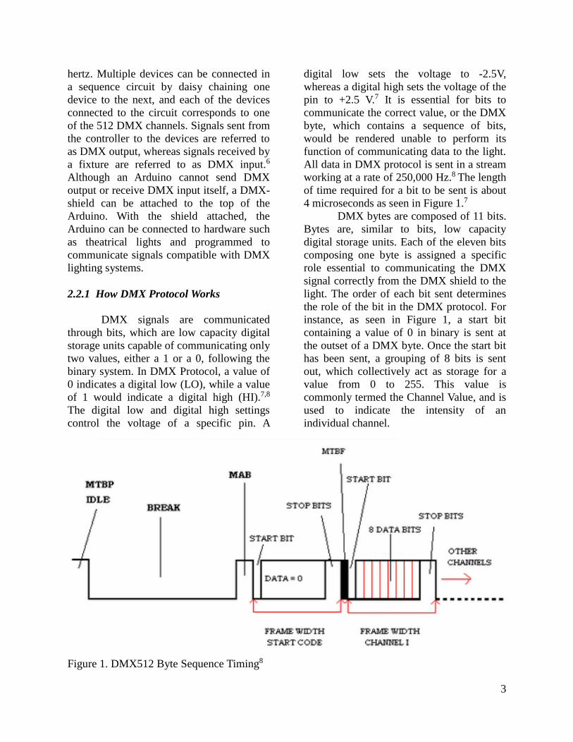
4 microseconds as seen in Figure 1.7
DMX bytes are composed of 11 bits.
Bytes are, similar to bits, low capacity
digital storage units. Each of the eleven bits
composing one byte is assigned a specific
role essential to communicating the DMX
signal correctly from the DMX shield to the
light. The order of each bit sent determines
the role of the bit in the DMX protocol. For
instance, as seen in Figure 1, a start bit
containing a value of 0 in binary is sent at
the outset of a DMX byte. Once the start bit
has been sent, a grouping of 8 bits is sent
out, which collectively act as storage for a
value from 0 to 255. This value is
commonly termed the Channel Value, and is
used to indicate the intensity of an
individual channel.
Figure 1. DMX512 Byte Sequence Timing8

4
In systems where the Arduino acts as
the master controller, the intensity can be
programmed in methods such as DmxSim-
ple.write(channel, brightness). The bright-
ness value will be communicated from the
code in the Arduino to the DMX shield, and
will then be translated into the proper volt-
age signals to be interpreted by the DMX
light.
Once the 8 bit sequence has been
sent out, another bit called the Stop bit will
be released. This bit is consistently set on
HI, meaning it holds a value of 1 in binary.
Following the Stop bit is the final bit,
termed the Release Bit, which also contains
a value of 1. Just as the Start bit signaled the
beginning of the byte, the Stop Bit and
Release bit indicate the end of the byte
sequence.7
Due to DMX-512 allowing access to
a total of 512 channels, to send a signal to
each of these channels, 512 bytes is
required. One byte is only capable of storing
a value for one Channel, since each byte can
contain only one 8 bit storage group. In
addition, since one byte in DMX is
composed of 11 bits, if each bit lasts 4
microseconds, one byte has a total duration
of 44 microseconds.7
2.3 Arduino
Arduino is modeled after Atmel’s
ATMEGA8 and ATMEGA168, both of
which are low power 8 bit microcontrollers.
Arduino is an open-source microprocessor
that provides users with a simple interface to
develop programs capable of
communicating with the physical world. The
aesthetic of the Arduino is a small, portable
board that is designed to function as a
microcontroller. It is commonly utilized to
create programs that send signals to interact
with physical objects such as LEDs or DMX
lights. The Arduino offers an inexpensive
and cross-platform environment that
beginners as well as experienced
programmers can use to develop software.2
2.3.1 Arduino Uno
The Arduino Uno functions with a
cable that connects to the standard USB port
of a computer. The cable connection allows
users to easily upload programs coded in the
Arduino environment onto the physical
board. The microprocessor is equipped with
fourteen digital input and output pins, as
well as six analog pins that can be connected
with wires to create circuits, and various
shields and sensors. It has a ceramic
resonator, a power jack, a reset button, and
an ICSP header.11
2.3.2 DMX-Shields
A DMX-Shield is a component of a
system using Arduino and DMX Protocol.
The Arduino board is unable to act as the
master controller of the light without the use
of a DMX-Shield. One of the primary roles
of the DMX-Shield is to convert the voltage
of the signals sent from the Arduino into a
set of voltages within the range that follows
DMX protocol.9
There is a variety of DMX Shields
that each has specific functions. For this
project, the TinkerKit DMX-Shield utilized
with the Arduino in the research process has
two connectors on top of the shield-an
INPUT DMX connector and an OUTPUT
connector.10 The TinkerKit DMX Shield is
used to drive a series of DMX receivers and
allows the Arduino to communicate with the
light. The INPUT connector which carries
signals to the shield was not relevant to the
research process as no signals were sent
from the light to the shield. The OUTPUT
connector, however, was required in order to
connect the DMX cable, which carries
signals from the shield to the light. If the
cable is not connected properly or the

5
connector is not inserted in the shield
sturdily enough, the light will not be able to
receive the proper signals to execute the
command.
Attaching the DMX-Shield to the
Arduino is a simple process. To attach the
DMX-Shield, the user must place the DMX-
Shield directly above the Arduino board,
match up the pins, and slide the DMX-
Shield into the pins of the Arduino board.
Similarly, the DMX Shield can be removed
by sliding the shield out of the pins.
Stacking shields is also made possible by
connecting another shield to the DMX-
shield the same way the DMX-shield was
attached to the Arduino.10 However, stacking
shields was not necessary for the current
research task.
In addition, the Arduino program
must be coded specifically for the DMX-
Shield in order for the code to be interpreted
correctly. A DMX Library compatible with
the specified version of the DMX-shield
must be downloaded in the Arduino
environment for the Arduino to
communicate properly to the shield.10
2.3.3 DMX Libraries
There are compiled libraries
downloadable in the Arduino environment
that effectively communicate DMX signals.
DmxSimple, a library created by TinkerKit,
can be used to output DMX signals to
different Arduino boards.5 DMXSimple has
several main methods that can be utilized for
lighting control. DmxSimple.write(channel,
brightness) controls which channel will be
set to a certain brightness.
DmxSimple.usePin(int pin) specifies
which pin on the Arduino board will output
the DMX signal. Pin 3 is the standard pin
and is set to the default pin by the
DMXSimple library. A third method,
DmxSimple.maxChannel(int channel)
specifies the set of channels exported to the
DMX device. The channel accessed with the
DmxSimple.write(channel, brightness)
method must not exceed the max channel in
order for the signals to be correctly
interpreted by the light.
Similar to DMXSimple, DMXSerial
and DMXSerial2 are two other libraries
capable of transmitting DMX signals.
DMXSerial is mainly used to construct
DMX Controllers and Devices. DMXSerial2
complies with DMX RDM protocol and is
often used in situations where signals must
be sent from the controller to the device, and
from the device back to the controller.5
2.4 Mega Par Profile Plus
The Mega Par Profile Plus is a PAR,
or Parabolic Aluminized Reflector light. It is
a lamp designed for stage lighting, with 107
LEDs. The Mega Par Profile Plus houses
LEDs that enable RGB color mixing, and an
ultraviolet black light. The light has five
operating modes: sound active mode, auto
mode, RGB + UV dimmer mode, static
color mode, and DMX control mode. The
light also has five DMX modes that may be
controlled via a DMX controller. A wireless
remote, the ADJ LED RC2, may be
optionally purchased which can be used to
control the light remotely.12
2.4.1 Mega Par Profile Plus Channels
The Mega Par Profile Plus light is
preprogrammed with multiple settings.
Depending on the Channel Mode selected on
the light, different channels can be accessed
in the Arduino program. As shown in Figure
2, to gain access to red, green, blue, and the
UV lights, the Channel Mode must be set to
4 Channel Mode. The 5 Channel Mode
allows for the Master Dimmer to be used,
and 6 Channel Mode gives the user access to
all of the previously mentioned effects as
well as strobing effects. The 8 Channel
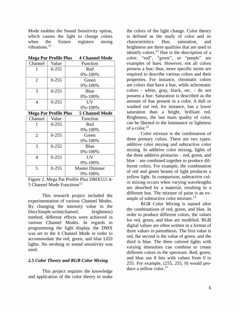
6
Mode enables the Sound Sensitivity option,
which causes the light to change colors
when the fixture registers strong
vibrations.12
Mega Par Profile Plus 4 Channel Mode
Channel Value Function
1 0-255 Red
0%-100%
2 0-255 Green
0%-100%
3 0-255 Blue
0%-100%
4 0-255 UV
0%-100%
Mega Par Profile Plus 5 Channel Mode
Channel Value Function
1 0-255 Red
0%-100%
2 0-255 Green
0%-100%
3 0-255 Blue
0%-100%
4 0-255 UV
0%-100%
5 0-255 Master Dimmer
0%-100%
Figure 2. Mega Par Profile Plus DMX512 4-
5 Channel Mode Functions12
This research project included the
experimentation of various Channel Modes.
By changing the intensity value in the
DmxSimple.write(channel, brightness)
method, different effects were achieved in
various Channel Modes. In regards to
programming the light display, the DMX
was set to the 4 Channel Mode in order to
accommodate the red, green, and blue LED
lights. No strobing or sound sensitivity was
used.
2.5 Color Theory and RGB Color Mixing
This project requires the knowledge
and application of the color theory to make
the colors of the light change. Color theory
is defined as the study of color and its
characteristics. Hue, saturation, and
brightness are three qualities that are used to
identify colors.13 Hue is the description of a
color; “red”, “green”, or “purple” are
examples of hues. However, not all colors
possess a hue; thus, more specific terms are
required to describe various colors and their
properties. For instance, chromatic colors
are colors that have a hue, while achromatic
colors - white, gray, black, etc. - do not
possess a hue. Saturation is described as the
amount of hue present in a color. A dull or
washed out red, for instance, has a lower
saturation than a bright, brilliant red.
Brightness, the last main quality of color,
can be likened to the luminance or lightness
of a color.13
Color mixture is the combination of
three primary colors. There are two types:
additive color mixing and subtractive color
mixing. In additive color mixing, lights of
the three additive primaries – red, green, and
blue – are combined together to produce dif-
ferent colors. For example, the combination
of red and green beams of light produces a
yellow light. In comparison, subtractive col-
or mixing occurs when varying wavelengths
are absorbed by a material, resulting in a
different hue. The mixture of paint is an ex-
ample of subtractive color mixture.13
RGB Color Mixing is named after
the combinations of red, green, and blue. In
order to produce different colors, the values
for red, green, and blue are modified. RGB
digital values are often written in a format of
three values in parenthesis. The first value is
red, the second is the value of green, and the
third is blue. The three colored lights with
varying intensities can combine to create
different colors in the spectrum. Red, green,
and blue use 8 bits with values from 0 to
255. For example, (255, 255, 0) would pro-
duce a yellow color.17
7
In the study, the Mega Par Profile
Plus lamp housed red, green, and blue LED
lights within it. By varying the intensities of
the red, green, and blue values in the
Arduino code, different colors were
produced from the light. Although if one
were to look at the light directly, red, green,
and blue LEDs would be visible, when one
looks at the spotlight on a surface, only a
single color—the result of color mixing—is
present.
3. Experimental
3.1 Programming in Arduino
The Arduino programming language
is based off of Wiring, a microcontroller
oriented programming framework.2, 16 An
Arduino sketch, a code written for Arduino
to run, has two required functions. One is
the setup() function, which runs only once
and is used to initialize any variables or
serial communication.14, 15 The next
necessary function is the loop() function
which repeats continuously. In general, a
function is a section of code that runs when
the function is called. Functions are often
used to simplify the structure of the program
and enable the user to reuse the same code.
In addition, multiple functions may be
stored in a library, which provides greater
functionality.14
Apart from functions, an Arduino
sketch contains variables, which store values
that may be used in the sketch. Variables can
be declared before setup() or in a function. A
variable declared before setup() is known as
a global variable and can be used anywhere
in the program. On the other hand, variables
declared in functions are known as local
variables and can only be used in that
function.15 Using both types functions
enables the user to code a variety of effects
using the same environment.
3.2 Developing Lighting Display
The research project emphasized the
development of a lighting display
choreographed in time with a short song.
The purpose of the display was to test the
feasibility of Arduino as an alternative
lighting console in the theatre industry. The
goal of the experiment was to identify and
analyze any inconveniences or advantages a
typical lighting technician could encounter
while working with the Arduino equipment,
and compare the results to the properties of a
standard lighting console.
The musical accompaniment to the
light display was a selection cut from a
string quartet piece titled “Palladio”, by Karl
Jenkins. This selection was chosen for its
strong beat and dramatic melody, which
allowed the light to easily be programmed to
flash or change colors in time with the beats.
A significant challenge to the experiment
was presented when the research group
attempted to time the light to change colors
in synchrony with the music. The light must
be pre-programmed and unlike more
expensive lighting control consoles, it does
not have a user interface that allows for
buttons or levers to be pushed that change
the lighting effects instantaneously.
Therefore, all of the musical dynamics must
be timed precisely to coincide with the
effects programmed in the code.
This required a mathematical as well
as musical approach. The group utilized the
sheet music of the song to mathematically
calculate the amount of beats in each
measure, as well as the length of each note
and wait period. The timing was produced
using the delay method in the Arduino
environment. In order to calculate the
amount of time of the musical score, the
given tempo of Palladio was divided by the
60 seconds in a minute. Since the given
tempo is equal to 90 beats per minute, 60
divided by 90 is equal to .667, which
8
converted to 667 milliseconds. However, the
value of 660 milliseconds was used because
the recording chosen was imperfect and
therefore requires minor changes to the
values.
The song itself consisted of notes of
a variety of lengths. Since there are four
sixteenth notes in one beat and each beat is
equal to 660 milliseconds, then one
sixteenth note is equal to 165 milliseconds.
There are two eighth notes in every beat, so
every eighth note is equal to 330
milliseconds. Using this idea of music
theory and mathematics, the delays were
calculated and implemented into the code.
4. Results and Observations
4.1 Functionality of Arduino Control
Board
Although the Arduino-based control
unit has a minimalistic interface that makes
it somewhat difficult to interact with lighting
fixtures, the DMX shield and the DMX
libraries for Arduino provide a solid
framework for creating most of the lighting
effects that a professional console is capable
of staging.
4.1.1 DMX Control
Although the Arduino itself does not
natively contain the functionality to send
DMX output or receive DMX input, the
TinkerKit DMX Master Shield can easily be
attached to the Arduino to enable
communication with any hardware that uses
the DMX protocol. Since DMX-512 is an
industry standard, the Arduino console with
the DMX shield is compatible with most
professional stage lighting equipment.
Although the project resources only allowed
the group to test with one light, additional
hardware can be daisy chained to the first
attached unit, giving the Arduino control
console the ability to control up to 512
DMX channels.6
4.1.2 Dimmer Effects
One of the core functions of a
control console is to interact with a dimmer
unit to quickly change the intensity of stage
lights. The DMXSimple library used to
program the Arduino contains a function
DmxSimple.write(channel,brightness) that
takes two parameter inputs. The first
parameter, channel, specifies the DMX
channel that the Arduino is interacting with.
The second parameter, value, specifies an
integer between 0 and 255 that corresponds
to the value that the user wants to set the
specified channel to. For example, if a
channel communicates with a light, then that
channel’s value corresponds with the
intensity of that light. A value of 0 means the
light is off. A value of 255 means the light is
at full brightness. The light can be written to
any intensity, either instantaneously or
through a gradual fading or brightening
effect, giving the user access to the core
functionality of a dimmer.
4.1.3 Color Effects
Any professional lighting console
provides access to color changing effects
that lighting directors can utilize to add to
the dramatic atmosphere. If the Arduino
control console is connected to hardware
that contains multicolored lights, the
Arduino can act as a centralized unit to
coordinate RGB color mixing. The light that
was used in the experiments was broken up
into three distinct sets of lights on three
different channels that each corresponded to
red, green, or blue lights, respectively. For
example, writing the red channel to 255
while writing the blue and green channels to
0 will create an entirely red light. By writing
each channel to a specific value, the Arduino
9
console can be used to create an entire
spectrum of colors. By setting all three lights
to equal values, the Arduino can also create
white light of varying intensity. In
conjunction with the dimmer effects, this
gives the Arduino the ability to choreograph
complicated effects that make it comparable
in functionality to a professional lighting
control board.
4.2 Ease and Efficiency of Use
While the DMX Shield and
DMXSimple library essentially give the
Arduino full control of any DMX hardware,
the Arduino control unit lacks an intuitive
user interface, making it somewhat difficult
to control lighting effects in real time.
4.2.1 Arduino Interface vs. Professional
Lighting Board
A professional lighting board has
numerous switches and sliders that cause the
console to run a program that sends DMX
signals to the hardware connected to the
console. The Arduino itself is a
microcomputer that cannot directly control
the light. When the DMX Shield is attached,
software that allows the Arduino to send
DMX signals can be written.
While this software can be written
easily enough, the Arduino does not have all
of the buttons that come on a commercial
lighting controller. Using the Arduino is not
as convenient as a standard lighting console
for quick changes. As such, there is no
efficient way to trigger lighting effects. For
example, although a program can easily
change the intensity of a light to a defined
value, a user cannot run this effect or specify
an input intensity value without completing
changing the code for the software and
uploading it to the Arduino again. This poses
a dilemma, as during a stage production a
lighting technician needs to have a
convenient and time-efficient way to
instantaneously execute visual effects.
4.2.2 Potential for a GUI
GUI stands for Graphical User
Interface which is the interface of a product
that allows the user to interact with
electronic devices through visual controllers.
Although the controls on most lighting
control consoles are fairly complicated and
difficult to learn, they provide an essential
level of user input and interaction that the
Arduino simply cannot provide on its own.
Fortunately, one could feasibly solve this
problem by using another language such as
Java to design a graphical user interface for
the Arduino program. Such an interface
would essentially emulate the controls of a
commercial lighting console, including
various buttons and sliders to control light
intensity and color. Instead of operating the
lights with physical controls, a lighting
technician would use a personal computer
with the GUI installed to execute the
necessary effects. Although programming a
GUI would require considerable additional
programming effort, it is certainly possible
and would be essential if the Arduino were
to be used as a viable alternative to
commercial lighting consoles.
4.3 Cost Analysis
The primary reason to consider using
an Arduino to create a theatrical lighting
console is to alleviate the heavy cost of
purchasing a commercial lighting board.
Despite the additional effort of
programming the Arduino and a GUI, using
an Arduino-based console has the potential
to save small theatrical companies thousands
of dollars in lighting equipment costs.
Using Arduino is most ideal for those
productions with limited funding.
10
4.3.1 Cost of a Commercial Console
A commercial lighting console
generally costs anywhere from several
hundred to several thousand dollars. A low-
end controller for a smaller theatre can
generally be purchased for under $1000. For
example, the Leviton MC7016 16-32
Channel DMX Lighting Control Console
costs $665.28.18 A mid-range console, such
as the Strand Lighting 250ML Portable
Lighting Control Console, can be purchased
for $2,099.95.19 This cost can continue to
increase as hardware is added to the console,
reaching $4,672.95 for the ETC Element
Control Console with 40 faders and 250
channels.20 Although these lighting consoles
are certainly more powerful than the
Arduino, the steep cost of a professional
console may often prove impractical and
inefficient for a small-scale theatrical
production.
4.3.2 Cost of Arduino Console
A homemade Arduino-powered
lighting console can be assembled for under
$100, making it considerably cheaper than
most commercial systems. On Amazon, an
Arduino Uno Rev. 3, which was used for the
experiments discussed in this paper, can be
purchased for $23.30.21 The Arduino
TinkerKit DMX Master Shield necessary for
sending DMX signals can be purchased for
$14.89.22 Together, this hardware can be
acquired and assembled for just below $40.
Programming the Arduino to perform
lighting effects is a simple and well-
documented task, so most users can utilize
online resources to set this up without
needing to pay additional money to a
programmer. Creating a GUI, however,
would be significantly more difficult,
making it likely that most theatrical
companies would have to hire someone to
create the software necessary to control the
Arduino. Although setup costs would most
likely exceed the estimate of $40 in most
cases, the entire system can still be
assembled for under $100, and would
certainly still prove to be cheaper than most
commercial systems.
5. Conclusions
The purpose of this research was to
investigate the potential for using an
Arduino microcontroller to design a cost-
effective theatrical lighting console.
Lighting effects are a core element of
theatre, but the current lighting control
technology on the market often costs
upwards of several thousand dollars, making
it difficult for smaller theatrical companies
to afford. Although an Arduino is not
natively capable of communicating through
the DMX protocol used to control stage
equipment, it can be outfitted with a DMX
shield to make it a potential inexpensive
alternative to commercial control systems.
The primary advantage of the
Arduino-based control console is that it
offers the core functionality of a
professional lighting console for a fraction
of the cost. The DMXSimple library
provides the Arduino with the functionality
to write DMX channels to any possible
value, allowing the controller to manage
standard lighting effects such as dimming
and color changes. Theoretically, this
application could be extended to other
theatrical equipment that uses DMX, such as
fog machines, allowing the console to
control even more complicated systems.
Considering the immense difference in the
prices of a commercial lighting console and
an Arduino with the DMX shield, the two
options offer comparable functionality.
Although the Arduino console is
functional enough to act as a competitive
alternative to commercial consoles, it has a
number of distinct drawbacks. Despite its
11
ability to control DMX equipment, the
Arduino microcontroller simply lacks the
hardware that a professional unit contains,
making it less powerful and less suitable for
large-scale productions. However, any
production that requires this level of lighting
can likely afford the necessary hardware.
Therefore, the Arduino controller is directed
primarily at small theatrical productions.
Although the lack of a built in UI for the
Arduino program is also a considerable
drawback, it can easily be rectified through
the creation of a GUI program that allows
convenient access to the Arduino’s software
from a personal computer.
Despite its limitations, the Arduino
with the DMX shield attachment is more
than capable of managing the majority of
lighting effects necessary for a typical stage
production. The necessary hardware to
create such a DIY console is considerably
less expensive than a professionally
designed system, and someone with minimal
coding experience can easily program most
of the necessary software for DMX lighting
control. As such, an Arduino with the DMX
attachment can serve as a viable alternative
to a professional lighting control console.
Acknowledgments
The authors of this paper would like
to thank a number of key people and entities
whose funding and support were essential to
the realization of this research project. First,
thank you to RTA advisor and mentor, Noah
Lee, for guiding the group’s research efforts
and supplying them with the necessary
hardware to perform the experiments with
Arduino and DMX. Second, the authors
would like to thank Dr. Ilene Rosen and
Dean Jean Patrick Antoine, Director and
Associate Director of the New Jersey
Governor’s School of Engineering and
Technology for providing the opportunity to
work on this project and publish the
research. Finally, the authors wish to thank
Rutgers, the State University of New Jersey,
Rutgers School of Engineering, The State of
New Jersey, Silver Line Windows,
Lockheed Martin, South Jersey Industries,
Novo Nordisk Pharmaceuticals, Inc., and
New Jersey Resources for their support and
contributions to the program.
Resources
1Larry Wild, “A Brief Outline of History of
Stage Lighting,” Northern State
University, 13 Nov 2013,
<http://www3.northern.edu/wild/Lite
Des/ldhist.htm> (13 July 2015). 2Arduino LLC, “Introduction,”
<https://www.arduino.cc/en/Guide/In
troduction> (7 July 2015). 3Instituto de Artes, “Stage Lighting and
Sound: History of Lighting and
Sound Recording <http://www.
iar.unicamp.br/lab/luz/ld/C%EAnica/
Hist%F3ria/stage_lighting_&_sound
_history_of_lighting_&_sound_recor
ding.pdf> (9 July 2015). 4Dan Radler, “The Gaslight Era,” Stage
Lighting: The CD-Rom,
<http://www.compulite.com/
stagelight/html/history-4/history-4-
text.html>, (8 July 2015). 5Arduino LLC, “DMX 512”
<http://playground.arduino.cc/Learni
ng/DMX> (7 July 2015). 6Lutron Electronics Co., Inc. “DMX-512
Fundamentals”
<http://www.lutron.com/en-US/
Education-Training/Documents/
DMX%20webinar_7-29-2010.pdf>
(7 July 2015). 7Arduino LLC, “The DMX Protocol”
<http://playground.arduino.cc/DMX/
Protokoll> (7 July 2015). 8Ujjal Kar, “The DMX 512 Packet”
<http://www.dmx512-online.com/
packt.html> (10 July 2015).

12
9Arduino LLC, “DMX-Shields”
<http://playground.arduino.cc/DMX/
DMXShield> (7 July 2015). 10Arduino LLC, “TinkerKit DMX Master
Shield” <https://store.arduino.cc/
product/T040060> (7 July 2015). 11Arduino LLC, “Arduino Uno”
<https://www.arduino.cc/en/Main/ar
duinoBoardUno> (7 July 2015). 12ADJ Products, LLC, “Mega Par Profile
Plus” <https://content.sakai.
rutgers.edu/access/content/group/9d9
dc959-da0a-49d5-be16-6cbff7> (5
July 2015). 13G.A. Agoston, Color Theory and Its
Application in Art and Design (
Springer-Verlag Berlin Heidelberg,
New York, 1987), p. 12-16,41-43. 14Arduino LLC, “Language Reference”
<https://www.arduino.cc/en/Referenc
e/HomePage> (6 July 2015). 15Arduino LLC, “Arduino Programming
Notebook” <http://playground.
arduino.cc/uploads/Main/arduino_no
tebook_v1-1.pdf> ( 6 July 2015). 16Wiring, “What Will YOU do with the W?”
<http://wiring.org.co/> (6 July 2015). 17Rapid Tables, “RGB Color Codes Chart”
<http://www.rapidtables.com/web/co
lor/RGB_Color.htm> (6 July 2015). 18Gear Techs, “Leviton MC7016 16-32
Channel DMX Lighting Control
Console” <http://geartechs.com/
store/lighting/leviton-mc7016-16-32-
channel-dmx-lighting-control-
console.html> (10 July 2015). 19Strand Lig1hting, “250 ML Lighting
Control Console” <http://www.
strandlighting.com/index.php?src=di
rectory&view=products&srctype=de
tail&back=products&refno=2650>
(10 July 2015).
20B&H “ETC Element Control Console - 40
Faders, 250 Channels”
<http://www.bhphotovideo.com/bnh/
controller/home?O=&sku=624896&
gclid=CjwKEAjw5pKtBRCqpfPK5q
XatWYSJABi5kTxOC3k0R4VY-
JDNLQdMA8wBzDReyEzMzYlEcg
ggWcpYBoC4b7w_wcB&is=REG&
A=details&Q=> (10 July 2015). 21Amazon Inc., “Arduino Uno Rev 3”
<http://www.amazon.com/Arduino-
A000066-Uno-Rev-3/dp/
B008GRTSV6/ref=sr_1_1?ie=UTF8
&qid=1437592130&sr=8-1
&keywords=arduino+uno+rev+3&pe
bp=1437592159707&perid=0QNR5
F5V4Z6004QA2FPT> (22 July
2015). 22Amazon Inc., “Arduino TinkerKit DMX
Master Shield T140060”
<http://www.amazon.com/Arduino-
TinkerKit-Master-Shield-T140060/
dp/B00EIB4ZF8/ref=sr_1_1?ie=UT
F8&qid=1437592299&sr=81&keyw
ords=dmx+tinkerkit+shield&pebp=1
437592318549&perid=1V1199NW1
JCAWRNWW2RF> (22 July 2015).