Embed Size (px)
Citation preview
Developing the UML as a Formal Modelling Notation
A. Evans1, R. France2, K. Lano3, B. Rumpe4
Abstract
The Unified Modeling Language (UML) is rapidly emerging as a de-facto standard formodelling OO systems. Given this role, it is imperative that the UML have a well-defined, fully explored semantics. Such semantics is required in order to ensure thatUML concepts are precisely stated and defined. In this paper we describe andmotivate an approach to formalizing UML in which formal specification techniquesare used to gain insight into the semantics of UML notations and diagrams. Wepresent work carried out by the Precise UML (PUML) group on the development of aprecise semantic model for UML class diagrams. The semantic model is used as thebasis for a set of diagrammatical transformation rules, which enable formaldeductions to be made about UML class diagrams. It is also shown how these rulescan be used to verify whether one class diagram is a valid refinement (design) ofanother. Because these rules are presented at the diagrammatical level, it will beargued that UML can be successfully used as a formal modelling tool without thenotational complexities that are commonly found in formal specification techniques.
1. Introduction
The popularity of object-oriented methods such as OMT [18] and the Fusion Method[4], stems primarily from their use of intuitively-appealing modelling constructs, richstructuring mechanisms, and ready availability of expertise in the form of trainingcourses and books. Despite their strengths, the use of OO methods on nontrivialdevelopment projects can be problematic. A significant source of problems is the lackof semantics for the modelling notations used by these methods. A consequence ofthis is that understanding of models can be more apparent than real. In some cases,developers can waste considerable time resolving disputes over usage andinterpretation of notation. While informal analysis, for example, requirements anddesign reviews, are possible, the lack of precise semantics for OO modelling makes itdifficult to develop rigorous, tool-based validation and verification procedures.
The Unified Modeling Language (UML) [13] is a set of OO modelling notations thathas been standardized by the Object Management Group (OMG). It is difficult todispute that the UML reflects some of the best modelling experiences and that itincorporates notations that have been proven useful in practice. Yet, the UML doesnot go far enough in addressing problems that relate to the lack of precision. The
1 Department of Computer Science, The University of York, UK2 Department of Computer Science & Engineering, Florida Atlantic University, USA3 Department of Computing, Imperial College, London, UK4 Department of Computer Science, Munich University of Technology, Germany
[EFL+98] A. Evans, R. France, K. Lano, B. Rumpe. Developing the UML as a Formal Modelling Notation. In: UML'98 Beyond the notation. International Workshop Mulhouse France. Pierre-Alain Muller, Jean Bezivin (eds.) Ecole Superieure Mulhouse, Universite de Haute-Alsace. 1998. www.se-rwth.de/publications

architects of the UML have stated that precision of syntax and semantics is a majorgoal. The UML semantics document (version 1.1) [12] is claimed to provide a“complete semantics” that is expressed in a “precise way” using meta-models and amixture of natural language and an adaptation of formal techniques that improves“precision while maintaining readability”. The meta-models do capture a precisenotion of the (abstract) syntax of the UML modelling techniques (this is what meta-models are typically used for), but they do little in the way of answering questionsrelated to the interpretation of non-trivial UML structures. It does not help that thesemantic meta-model is expressed in a subset of the notation that one is trying tointerpret. The meta-models can serve as precise description of the notation and aretherefore useful in implementing editors, and they can be used as a basis to definesemantics, but they cannot serve as a precise description of the meaning of UMLconstructs.
The UML architects justify their limited use of formal techniques by claiming that“the state of the practice in formal specifications does not yet address some of themore difficult language issues that UML introduces”. Our experiences withformalizing OO concepts indicate that this is not the case. While this may be true tosome extent, we believe that much can be gained by using formal techniques toexplore the semantics of UML. On the other hand, we do agree that current text-basedformal techniques tend to produce models that are difficult to read and interpret, and,as a result, can hinder understanding of UML concepts. This latter problem does notdiminish the utility of formal techniques, rather, it obligates one to translate formalexpressions of semantics to a form that is digestible by users of the UML notation.
In a previous paper [8], we discuss how experiences gained by formalizing OOconcepts can significantly impact the development of a precise semantics for UMLstructures. We motivated an approach to formalizing UML concepts in whichformal specification techniques are used primarily to gain insights tothe semantics ofUML notations. In this paper we present the roadmap we are using to formalize theUML, and describe the results of its application to the formalization of UML staticmodels.
The primary objective of our work is to produce rigorous development techniquesbased on the UML. A first step is to make UML models amenable to rigorousanalyses by providing a precise semantics for the models. This paves the way for thedevelopment of formal techniques supporting the rigorous development of systemsthrough the systematic enhancement and transformation of OO models. In this paperwe show how the formalized static model can be rigorously manipulated to proveproperties about them and their relationships to other static models.
In section 2, we give an overview of work on the formalization of OO modellingconcepts and notations, and outline the PUML formalization approach. In section 3we present the results of our work on formalizing UML static models, and in section4we show how the resulting static model diagrams can be formally manipulated.
We conclude in section 5 with a summary and a list of some of the open issues thathave to be tackled if our approach is to bear meaningful results.
2. Formalizing OO Concepts: Overview and Roadmap
Classification of Approaches
In [8] we identified three general approaches to formalizing OO modelling concepts:supplemental, OO-extended formal notation, and methods integration approaches. Inthe supplemental approach more formal statements replace parts of the informalmodels that are expressed in natural language. Syntropy [5] uses this approach. In theOO-extended formal language approach, an existing formal notation (e.g. Z [20]) isextended with OO features (e.g. Z++ [17] and Object-Z [ 6]). In the methodsintegration approach informal OO modelling techniques are made more precise andamenable to rigorous analysis by integrating them with a suitable formal specificationnotation (e.g., see [9,2,14]).
Most method integration works involving OO methods focus on the generation offormal specifications from less formal OO models. This is in contrast to the PUMLobjectives, where the OO models are the precise (even formal) models. The degree offormality of a model is not necessarily related to its form of representation. Inparticular, graphical notations can be regarded as formal if a precise semantics isprovided for their constructs.
A formal semantics for a modelling notation can be obtained by defining a mappingfrom syntactic structures in the (informal) modelling domain to artifacts in theformally defined semantic domain. This mapping, often called a meaning function, isused to build interpretations of the informal models.
Rather than generate formal specifications from informal OO models and require thatdevelopers manipulate these formal representations, a more workable approach is toprovide formal semantics for graphical modelling notations and develop rigorousanalysis tools that allow developers to directly manipulate the OO models they havecreated. Defining meaning functions provides opportunities for exploring and gaininginsight into appropriate formal semantics for graphical modelling constructs.The method developers (and not the application developers) should use thesemappings to justify the correctness of analysis tools and procedures provided in aCASE tool environment.
Roadmap to Formalization
Our experiences with formalizing OO modelling notations indicate that a precise anduseful semantics must be complete (i.e., meanings must be associated with each well-formed syntactic structure), preserve the intended level of abstraction(i.e., the elements in the semantic domain must be at the same level of abstraction astheir corresponding modelling concepts), and understandable by method developers.Furthermore, the formalization of a heterogeneous set of modelling techniquesrequires that the notations be integrated at the semantic level. Such integration isrequired if dependencies across the modelling techniques are to be defined.
The following are the steps of the formalization approach that we use in our work onformalizing the UML:
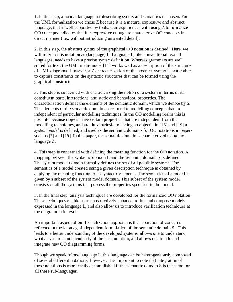
1. In this step, a formal language for describing syntax and semantics is chosen. Forthe UML formalization we chose Z because it is a mature, expressive and abstractlanguage, that is well supported by tools. Our experiences with using Z to formalizeOO concepts indicates that it is expressive enough to characterize OO concepts in adirect manner (i.e., without introducing unwanted detail). 2. In this step, the abstract syntax of the graphical OO notation is defined. Here, wewill refer to this notation as (language) L. Language L, like conventional textuallanguages, needs to have a precise syntax definition. Whereas grammars are wellsuited for text, the UML meta-model [11] works well as a description of the structureof UML diagrams. However, a Z characterization of the abstract syntax is better ableto capture constraints on the syntactic structures that can be formed using thegraphical constructs.
3. This step is concerned with characterizing the notion of a system in terms of itsconstituent parts, interactions, and static and behavioral properties. Thecharacterization defines the elements of the semantic domain, which we denote by S.The elements of the semantic domain correspond to modelling concepts that areindependent of particular modelling techniques. In the OO modelling realm this ispossible because objects have certain properties that are independent from themodelling techniques, and are thus intrinsic to “being an object”. In [16] and [19] asystem model is defined, and used as the semantic domains for OO notations in paperssuch as [3] and [19]. In this paper, the semantic domain is characterized using thelanguage Z.
4. This step is concerned with defining the meaning function for the OO notation. Amapping between the syntactic domain L and the semantic domain S is defined.The system model domain formally defines the set of all possible systems. Thesemantics of a model created using a given description technique is obtained byapplying the meaning function to its syntactic elements. The semantics of a model isgiven by a subset of the system model domain. This subset of the system modelconsists of all the systems that possess the properties specified in the model.
5. In the final step, analysis techniques are developed for the formalized OO notation.These techniques enable us to constructively enhance, refine and compose modelsexpressed in the language L, and also allow us to introduce verification techniques atthe diagrammatic level.
An important aspect of our formalization approach is the separation of concernsreflected in the language-independent formulation of the semantic domain S. Thisleads to a better understanding of the developed systems, allows one to understandwhat a system is independently of the used notation, and allows one to add andintegrate new OO diagramming forms.
Though we speak of one language L, this language can be heterogeneously composedof several different notations. However, it is important to note that integration ofthese notations is more easily accomplished if the semantic domain S is the same forall these sub-languages.
In the following sections, we illustrate the application of this formalization approachusing a small subset of UML class diagram notation.
3. A Formalization Example
In this section we formally define the abstract syntax of a subset of the UML staticmodel notation, characterize an appropriate semantic domain for its components, anddefine a meaning function for the formally defined syntax.
Abstract Syntax
In the UML semantics document (version 1.1), the core package - relationships -gives an abstract syntax for the static components of the UML. This is described atthe meta-level using a class diagram with additional well-formedness rules given inOCL. For reasons given in the previous section, we use the Z notation to define theabstract syntax. Unlike the OCL, Z provides good facilities for proof. In our work wetreat the UML semantics document as a requirements statement from which a fullyformal model can be obtained.
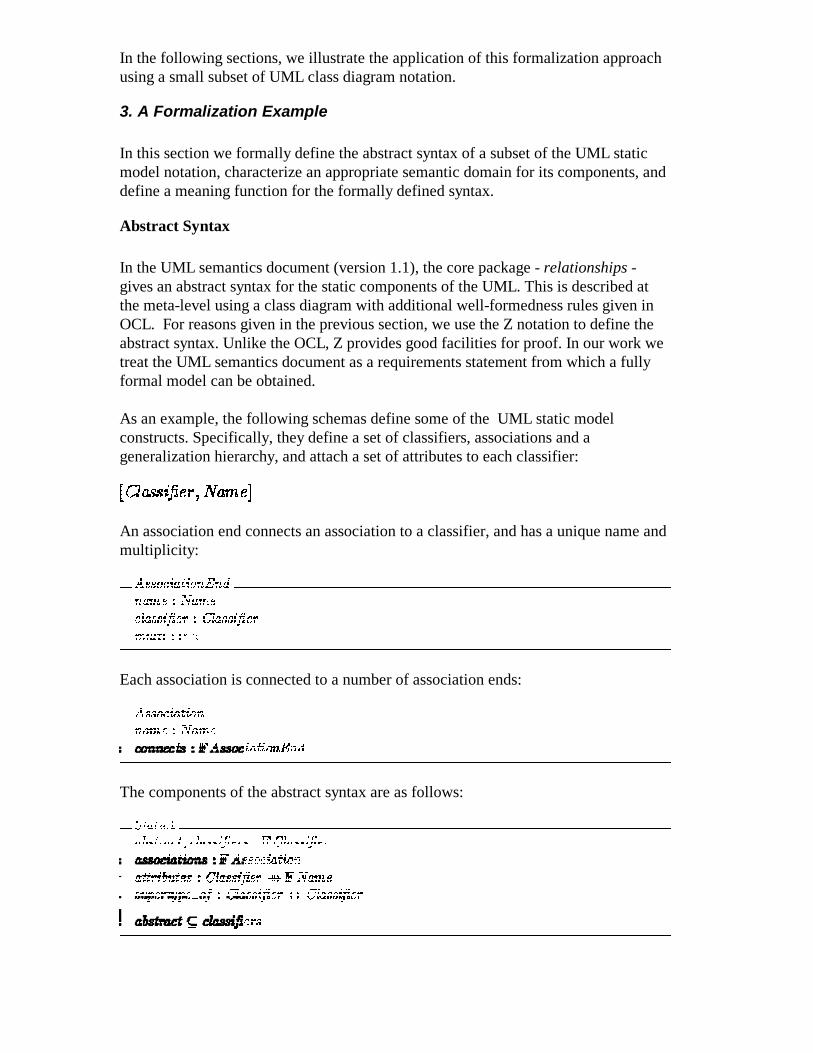
As an example, the following schemas define some of the UML static modelconstructs. Specifically, they define a set of classifiers, associations and ageneralization hierarchy, and attach a set of attributes to each classifier:
An association end connects an association to a classifier, and has a unique name andmultiplicity:
Each association is connected to a number of association ends:
The components of the abstract syntax are as follows:
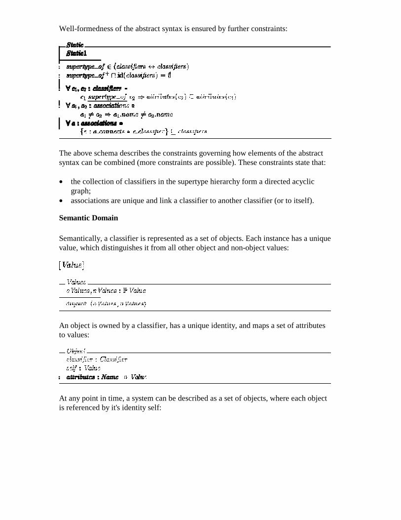
Well-formedness of the abstract syntax is ensured by further constraints:
The above schema describes the constraints governing how elements of the abstractsyntax can be combined (more constraints are possible). These constraints state that:
• the collection of classifiers in the supertype hierarchy form a directed acyclicgraph;
• associations are unique and link a classifier to another classifier (or to itself).
Semantic Domain
Semantically, a classifier is represented as a set of objects. Each instance has a uniquevalue, which distinguishes it from all other object and non-object values:
An object is owned by a classifier, has a unique identity, and maps a set of attributesto values:
At any point in time, a system can be described as a set of objects, where each objectis referenced by it's identity self:
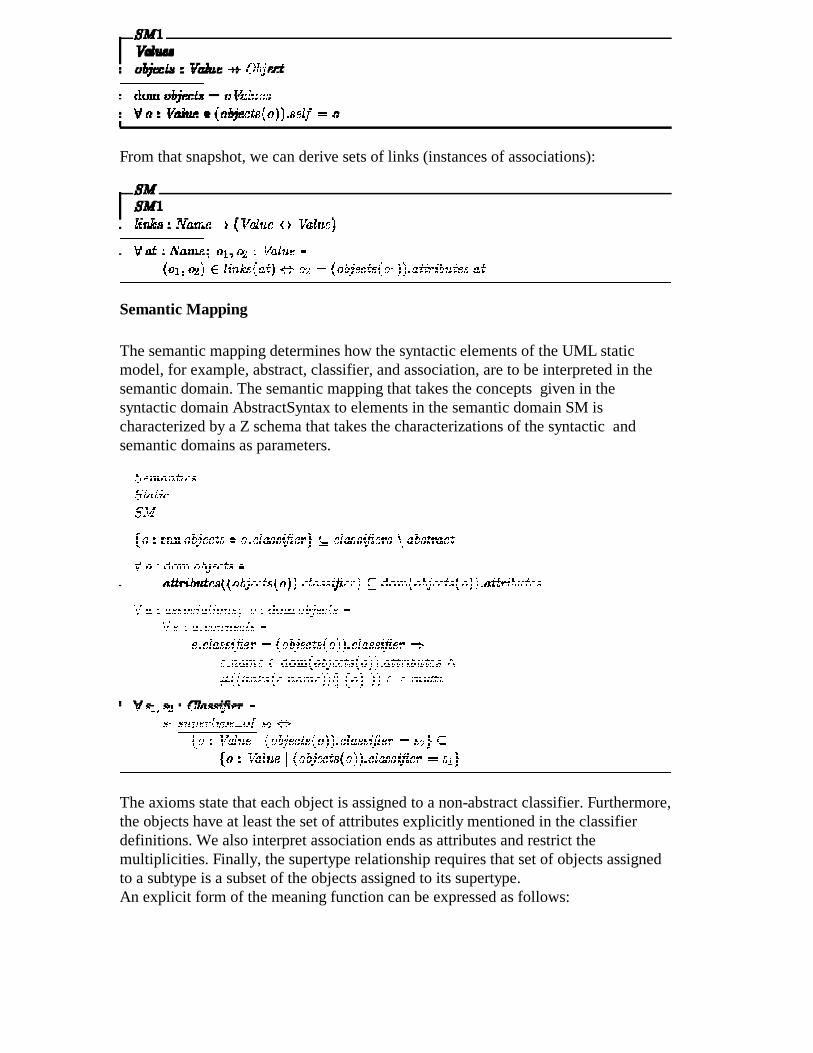
From that snapshot, we can derive sets of links (instances of associations):
Semantic Mapping
The semantic mapping determines how the syntactic elements of the UML staticmodel, for example, abstract, classifier, and association, are to be interpreted in thesemantic domain. The semantic mapping that takes the concepts given in thesyntactic domain AbstractSyntax to elements in the semantic domain SM ischaracterized by a Z schema that takes the characterizations of the syntactic andsemantic domains as parameters.
The axioms state that each object is assigned to a non-abstract classifier. Furthermore,the objects have at least the set of attributes explicitly mentioned in the classifierdefinitions. We also interpret association ends as attributes and restrict themultiplicities. Finally, the supertype relationship requires that set of objects assignedto a subtype is a subset of the objects assigned to its supertype.An explicit form of the meaning function can be expressed as follows:
4. Analyzing UML diagrams
As discussed above, a central part of the PUML group's work is to develop a formalversion of UML that can be used to build precise and analyzable models. However,how can a UML model be analyzed? In the case of a textual notation such as Z,analysis is carried out by constructing proofs to determine the truth or falsity of someproperty being asserted about a specification. Each proof involves applying asequence of inference rules and axioms to the specification to derive the requiredconclusion. At each step, a new formula is derived either from the originalspecification or as a result of applying an inference rule to previous formulas.
To analyze UML models, a very similar approach can be adopted [7]. However,because UML is a diagrammatical modelling language, a set of deductive rules forUML will consist of a set of diagrammatical transformation rules. Thus, proving aproperty about a UML model will involve applying a sequence of transformation rulesto the model diagrams until the desired conclusion is reached. As an example,consider a class diagram, which describes the relationship between a university andits students. If a student can be specialized as being either part-time or full-time, canit be deduced (by suitable transformations) that the university has the samerelationship with a full-time student as it has with all students?
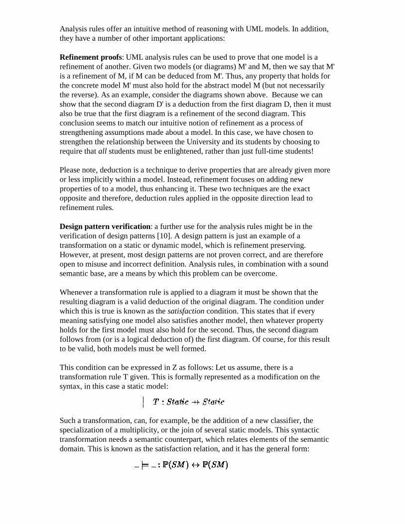
The following diagrams can express this (obviously correct) theorem. Here thediagram on the right expresses the theorem to be proved:
Using a suitable sequence of transformation rules, we should be able o transform theoriginal diagram into the second diagram, thereby roving that the theorem is valid. Inthis case, three steps are required to carry out the proof, each of which is the result ofapplying a specific transformation rule. The first step is to introduce a newassociation (e.g. new) between University and Part-time as a weakened version ofenlightens. The second step is to erase the original association enlightens. The proofis completed by renaming new to enlightens.
Analysis rules offer an intuitive method of reasoning with UML models. In addition,they have a number of other important applications:
Refinement proofs: UML analysis rules can be used to prove that one model is arefinement of another. Given two models (or diagrams) M' and M, then we say that M'is a refinement of M, if M can be deduced from M'. Thus, any property that holds forthe concrete model M' must also hold for the abstract model M (but not necessarilythe reverse). As an example, consider the diagrams shown above. Because we canshow that the second diagram D' is a deduction from the first diagram D, then it mustalso be true that the first diagram is a refinement of the second diagram. Thisconclusion seems to match our intuitive notion of refinement as a process ofstrengthening assumptions made about a model. In this case, we have chosen tostrengthen the relationship between the University and its students by choosing torequire that all students must be enlightened, rather than just full-time students!
Please note, deduction is a technique to derive properties that are already given moreor less implicitly within a model. Instead, refinement focuses on adding newproperties of to a model, thus enhancing it. These two techniques are the exactopposite and therefore, deduction rules applied in the opposite direction lead torefinement rules.
Design pattern verification: a further use for the analysis rules might be in theverification of design patterns [10]. A design pattern is just an example of atransformation on a static or dynamic model, which is refinement preserving.However, at present, most design patterns are not proven correct, and are thereforeopen to misuse and incorrect definition. Analysis rules, in combination with a soundsemantic base, are a means by which this problem can be overcome.
Whenever a transformation rule is applied to a diagram it must be shown that theresulting diagram is a valid deduction of the original diagram. The condition underwhich this is true is known as the satisfaction condition. This states that if everymeaning satisfying one model also satisfies another model, then whatever propertyholds for the first model must also hold for the second. Thus, the second diagramfollows from (or is a logical deduction of) the first diagram. Of course, for this resultto be valid, both models must be well formed.
This condition can be expressed in Z as follows: Let us assume, there is atransformation rule T given. This is formally represented as a modification on thesyntax, in this case a static model:
Such a transformation, can, for example, be the addition of a new classifier, thespecialization of a multiplicity, or the join of several static models. This syntactictransformation needs a semantic counterpart, which relates elements of the semanticdomain. This is known as the satisfaction relation, and it has the general form:
The satisfaction relation forms the basis for unambiguously defining the conditionsunder which a diagram can be considered to satisfy the properties of another diagram.Defining suitable satisfaction conditions for this relation will be an essential steptowards our aim of developing rigorous analysis methods for UML. For example, onepossible satisfaction relation might permit both introduction and deletion of classes asa deductive step, whilst another might only permit class introduction5.
Finally, the formal proof of correctness of a transformation can now be describedwithin Z (and therefore can be proven within Z). A transformation T is correct, if
This strongly corresponds to the commuting diagram, first stated in [19] and also in[15].
5. Summary and Open Issues
In this paper we outlined and illustrated an approach to formalizing the UML.The objective of our efforts is to make the UML itself a precise modelling notation sothat it can be used as the basis for a rigorous software development method. However,it must first be determined how such a formalization can best be carried out, and whatpractical purpose it can serve. This paper aims to contribute to this ongoingdiscussion.
The benefits of formalization can be summarized as follows:
• Lead to a deeper understanding of OO concepts, which in turn can lead to moremature use of technologies.
• The UML models become amenable to rigorous analysis. For example, rigorousconsistency checks within and across models can be supported.
• Rigorous refinement techniques can be developed.
An interesting avenue to explore is the impact a formalized UML can have on OOdesign patterns and on the development of rigorous domain-specific softwaredevelopment notations. Domain-specific UML patterns can be used to bring UMLnotations closer to a user's real-world constructs. Such patterns can ease the task ofcreating, reading, and analyzing models of software requirements and designs.
An integrated approach to formalization of UML models is needed in order to providea practical means of analyzing these models. Current work on compositionalsemantics [1] has used techniques for theory composition to combine semanticinterpretations of different parts of an OO model set.
5 At present we are investigating a number of different satisfaction relations for UML diagrams in orderto determine which best fits emerging practice.
Some of the other issues that have to be addressed in our work follows:
• How does one gauge the appropriateness of an interpretation of UML constructs?In practice an `accepted' interpretation is obtained by consensus within a group ofexperts. Formal interpretations can facilitate such a process by providing clear,precise statements of meaning.
• Should a single formal notation be used to express the semantics for all themodels? The advantage of a single notation is that it provides a base for checkingconsistency across models, and for refinement of the models. This is necessary ifanalysis and refinement is done at the level of the formal notation. On the otherhand, if the role of the formal notation is to explore the semantic possibilities forthe notations, and analysis and refinement are carried out at the UML level, thenthere seems to be no need to use a single formal notation.
It is anticipated that as our work progresses additional issues that will have to betackled will surface.
Bibliography
[1] J.Bicarregui, K.Lano, and T.Maibaum. Objects, associations and subsystems: A heirarchical approach toencapsulation. In Proceedings of ECOOP 97, LNCS 1489. Springer-Verlag, 1997.
[2] Robert H. Bourdeau and Betty H.C. Cheng. A formal semantics for object model diagrams.IEEE Transactions on Software Engineering}, 21(10):799--821, October 1995.
[3] Ruth Breu, Ursula Hinkel, Christoph Hofmann, Cornel Klein, Barbara Paech,Bernhard Rumpe, and Veronika Thurner. Towards a formalization of the unified modeling language.In SatoshiMatsuoka MehmetAksit, editor, ECOOP'97 Proceedings. Springer Verlag, LNCS 1241, 1997.
[4] Derek Coleman, Patrick Arnold, Stephanie Bodoff, Chris Dollin, Helena Gilchrist, Fiona Hayes, and PaulJeremaes. Object-Oriented Development: The Fusion Method. Prentice Hall, Englewood Cliffs, NJ, Object-OrientedSeries, 1994.
[5] Steve Cook and John Daniels. Let's get formal. Journal of Object-Oriented Programming (JOOP), pages 22--24and 64--66, July--August 1994.
[6] Roger Duke, Paul King, GordonA. Rose, and Graeme Smith. The Object-Z specification language. In Timothy D.Korson, VijayK. Vaishnavi, and Bertrand Meyer, editors, Technology of Object-Oriented Languages and Systems:TOOLS 5, pages 465--483. Prentice Hall, 1991.
[7] A.Evans. A logical foundation for {UML} diagrams. In Visual'98 (ETAPS'98), Lisbon, 1998.
[8] Robert France, Andy Evans, Kevin Lano, and Bernard Rumpe. The [UML] as a formal modeling notation.Submitted to Computer Standards and Interfaces, 1998.
[9] Robert B. France, Jean-Michel Bruel, and MariaM. Larrondo-Petrie. An Integrated Object-Oriented and FormalModeling Environment. Journal of Object-Oriented Programming (JOOP)}, 1998.
[10] E.Gamma, R.Helm, R.Johnson, and J.Vlissides. Design Patterns: Elements of Reusable Software. Addison-Wesley, 1995.
[11] The UML Group. UML Metamodel. Version 1.1, Rational Software Corporation, Santa Clara, CA-95051,USA, September 1997.
[12] The UML Group. UML Semantics. Version 1.1, Rational Software Corporation, Santa Clara, CA-95051, USA,July 1997.
[13] The UML Group. Unified Modeling Language. Version 1.1, Rational Software Corporation, Santa Clara, CA-95051, USA, July 1997.
[14] J.Anthony Hall. Using Z as a specification calculus for object-oriented systems.In D.Bjorrner, C.A.R. Hoare, and H.Langmaack, editors, VDM and Z -- Formal Methods in Software Development,volume 428 of LNCS , pages 290--318. VDM-Europe, Springer-Verlag, New York, 1990.
[15] H. Kilov and B.Rumpe. Precise semantics for object-oriented modelling techniques. In Object-OrientedTechnology, Workshop Reader, LNCS 1357, pages 145--150. Springer Verlag Berlin, 1997.
[16] Cornel Klein, Bernhard Rumpe, and Manfred Broy. A stream-based mathematical model for distributedinformation processing systems - SysLab system model. In Jean-BernardStefani ElieNaijm, editors FMOODS '96Formal Methods for Open Object-based Distributed Systems, pages 323--338. ENST. France Telecom, 1996.
[17] Kevin. C Lano. Z++, an object-orientated extension to Z. In John E. Nicholls, editor, Z User Workshop, Oxford1990, Workshops in Computing, pages 151--172. Springer-Verlag, 1991.
[18] J.Rumbaugh, M.Blaha, W.Premerlani, F.Eddy, and W.Lorensen. Object-Oriented Modeling and Design.Prentice Hall, 1991.
[19] B.Rumpe. Formal Method for Design of Distributed Object-oriented Systems. Ph.d. thesis (in german),Technische Universitat Munchen, 1996.
[20] J .Michael Spivey. The Z Notation: A Reference Manual}. Prentice Hall, Englewood Cliffs, NJ, Second edition,1992.