Embed Size (px)
Citation preview
1
Developing the Strength and Ductility of Shear Stud Connection in Deep Profiled Decking
*Ahmed Albarram1, Jawed Qureshi2 and Ali Abbas2
1, 2School of Architecture, Computing and Engineering, University of East London, E16 2RD, London, United Kingdom
ABSTRACT
Three-dimensional finite element push-off models were conducted by ABAQUS/Explicit package. This study aims to enhance the strength and ductility of shear connection in deep profiled decking of 146 mm. Two steel reinforcement techniques were investigated which are double wire-mesh reinforcement and embedding steel bars within the ribs at different heights from the bottom surface of deep profiled decking. The target was to observe the capability of these two techniques of suppressing the premature brittle failure of concrete in order to improve the strength and ductility. The numerical results revealed that the use of double wire-mesh reinforcement made the push models end with sufficient ductility. However, this technique was not able to enhance the shear connector resistance and suppress the premature concrete failure within the ribs. It was noticed that placing steel bars at 50 mm from the bottom surface of decking led both strength and ductility to improve, besides suppressing the concrete damage patterns. It was concluded that the shear connection in deep profiled decking is mainly governed by the concrete embedded within the ribs, and reinforcing that area would enhance the strength and ductility.
Key words: Push-off test, deep profiled decking, headed shear stud, ductility, ABAQUS. 1. Introduction
Steel-concrete composite beams with profiled steel decking are commonly used in constructions. A profiled steel decking is fixed by means of shear connectors welded through the thin surface of decking prior to casting of the concrete. The main benefit of profiled steel decking is to work as a permanent formwork to the concrete slab and resist the tensile forces after the concrete hardens. In addition, a profiled steel decking can reduce the need for propping, therefore, it provides an economical solution. Testing full-scale composite beams is the traditional way to investigate the performance of composite beams. Alternatively, push-off tests can be used to determine the shear connector
1 PhD Candidate
2 Senior Lecturer
2
resistance, ductility and failure modes in composite beams due to their cost and time saving (Ernest et al 2006).
The results obtained from the push-off tests in various research have revealed significant reduce in strength and ductility of the shear connection as compared to the conventional results from full-scale composite beams. It is believed that the deficiency in the results of push-off tests is because of the push test method develops extra uplift effects in the concrete slab and force transfer method which are different to those in full-scale beams (Bradford et al 2008). This trend results premature failures in concrete which in turn reflects on the strength and ductility of shear connection in push-off tests. Therefore, many studies have been conducted to modify the standard methodology of push-off test in different codes (e.g. the European code 4), the target was to prevent a premature failure of concrete from happening. Some methods have been noticed capable of developing the strength and ductility of shear connection such as a waveform reinforcement (Patrick 2000), spiral stud enhancing device (Ernest et al 2004), and normal load application (Bradford et al 2006).
The concrete slab is normally reinforced by a single wire-mesh steel to improve the resistance in the push-off tests against the longitudinal shear forces and to control the cracks in the concrete part. In fact, there is a limit in research about the effect of double wire-mesh reinforcement on the behaviour of shear connections (Placing one mesh at the top surface of decking, and the other at a distance from the upper surface of concrete). Also, embedding individual steel bars within ribs at different heights from the bottom surface of deep decking has received no attention. These parameters may provide an alternative technique than some previous methods mentioned as those might be expensive and hard to implement in some cases, while the proposed technique in the current research can be easier to implement.
The total depth of profiled decking has recently increased to 146 mm. There is a necessity to investigate the behaviour of composite beams with deep profiled decking due to the lack of research on that modern material. As a matter of fact, neither the European code (EC4) nor the American specification (ANSI/AISC) provide standard guidance about the composite beams when the depth of decking is more than 80 mm. Hence, this research aims to study the strength and ductility of shear connection in push-off test with deep steel decking, and to what extent the number of wire mesh reinforcement as well as the steel bars embedded within the ribs may affect the performance of shear connection regarding the strength and ductility. The push-off tests are numerically conducted by three-dimensional finite element models in ABAQUS.
2. Description of push-off models with 146 mm profiled steel decking 2.1 General
The behaviour of shear connection in composite beams with deep profiled decking was investigated. The current research was used ABAQUS/Explicit package to perform three-dimensional finite element models to simulate push-off tests with 146 mm profiled decking. It has been noticed that ABAQUS has ability to simulate many types of structures,
3
particularly those with complicated contact interaction such as a push-off test. Several researchers such as Mirza and Uy (2008), Nguyen and Kim (2009), and Qureshi and Lam (2012) used ABAQUS package to investigate the behaviour of shear connection in push test with or without profiled decking in which ABAQUS was successfully capable of catching the mechanism of load-slip capacity and mode of failure with different parametric studies.
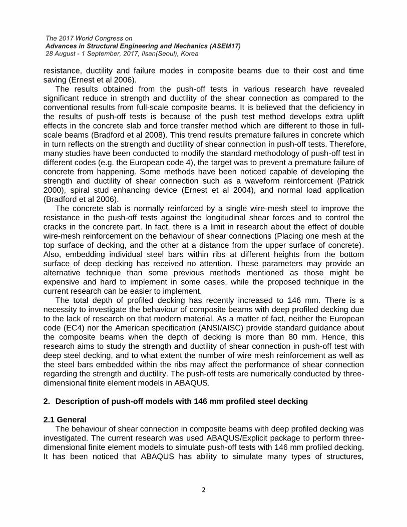
All push-off models were numerically analyzed based on a horizontal push test arrangement. A full-scale push-off test was modelled including five ribs of deep profiled decking in which the length of concrete slab was approximately 1120 mm. The steel decking was oriented perpendicular to the steel beam, and the section of steel beam was chosen to be 254 × 254 × 73 UC. Since the effect of I-steel beam is negligible on the behaviour of composite beams during the test, only the upper flange of steel beam was modelled. The profiled decking had a net total depth (hp) of 146 mm, average trough width (bo) of 97.5 mm, and sheeting thickness (ts) of 1.2 mm (Kingspan Company 2011). A headed stud dimension of 19 × 195 mm long was used as shear connectors in all push tests. Because of the narrowness at the bottom surface of sheeting’s ribs, it was not possible to place the headed studs anywhere but in the center. Therefore, the headed studs were positioned in the center of troughs through the profiled sheeting in all models.
Normal weight concrete was used to identify the concrete slab geometry in all push models. The width of concrete slab in all models was 600 mm, as it is the minimum width requirement in the standard push test arrangement of the European code (EC4), and the total slab depth was 215 mm. The wire mesh reinforcement was identified by a steel bar of 7 mm in diameter with 200 centre to centre spacing, while the steel bars embedded within the ribs of decking were identified by steel bars of 12 mm in diameter. All geometries were meshed using 15 × 15 mm mesh element size and then assembled together to produce the push test model, the general push test arrangement is shown in Fig. 1. The concrete slab was raised in this figure to enable the embedded parts inside the concrete to be seen.
Fig. 1. General push test arrangement with 146 mm profiled sheeting
4
2.2 Material modelling for steel parts In the finite element modelling, the headed shear stud was modelled together with the
steel beam, yet the properties for each part were different. Since the steel beam has no essential effect on the behaviour of headed studs during the push test, thereby the steel beam part was treated as fully elastic material, this approach was successfully used by Qureshi et al (2011a). The Young’s modulus of elasticity of the steel beam was taken as 210 GPa, whilst 200 GPa was assumed for the rest steel components. The headed studs, profiled sheeting, steel bars, and wire mesh reinforcement were considered fully plastic, and the yield stress was taken as 420 MPa, 350 MPa, 400 MPa, and 460 MPa respectively. Finally, the density of all steel parts was taken as 7800 kg/m3.
2.3 Material modelling for concrete
Concrete is defined as a brittle material in which inelastic behaviour is undoubtedly considered. Hence, a proper technique in the finite element analysis should be capable of covering the full inelastic behaviour of concrete in both compression and tension including damage patterns. In this research, the Concrete Damage Plasticity method was used to identify the concrete slab. Concrete Damage Plasticity considers the degradation of the elastic stiffness which is made by the plastic straining in compression and tension. Two main failure mechanisms define this model namely tensile cracking and compressive crushing. Softening stress-strain response represents the post-failure under compression. While, tension stiffening represents the strain softening of the concrete cracks regarding a fracture energy cracking or post-failure stress-strain behaviour in tension (ABAQUS Documentation 2014). This method was extensively explained by Qureshi et al (2011a). The density and poisson’s ratio of concrete were chosen as 2400 kg/m3 and 0.2 respectively.
2.4 Contact interactions and constrains
A surface to surface contact (explicit) interaction with a contact pair algorithm was used in finite element model to specify the contacted surfaces. The tangential and normal behavior are used to define the interaction properties between surfaces. The normal behavior is identified by the default option “Hard” contact pressure-overclosure which allows a slave surface to penetrate a master surface. All surfaces contact between concrete and steel material were specified as frictional with a coefficient of friction of 0.5, while the interaction properties for the contact surface between underside profiled troughs and steel beam flange was considered frictionless. By using the tie constrain method, the nodes of profiled sheeting around the headed stud circumference were tied to the nodes of headed shank at the base. In terms of the steel bars and wire mesh reinforcement, the materials were embedded inside the concrete slab using the embedded constrain method.
2.5 Boundary conditions and load application
The boundary conditions and load application were similar in all push models. All nodes of the lower surface of steel beam were restrained from moving and rotating in all directions. From one of the concrete side, all models were pushed horizontally and slowly
5
until failure using a loading rate of 0.5 mm/sec and mass scaling factor of 10 to ensure the quasi-static solution in ABAQUS/Explicit. The average slip capacity was measured at the concrete surface opposite to the shear load surface, and the shear strength of headed stud was calculated by dividing the total failure load by the number of headed studs embedded in the concrete slab.
3. Test program and results
Four push-off models were initially conducted. The concrete slab in two of them was reinforced by a single wire-mesh placing at the surface of profiled decking (bottom position). The other two models had the concrete slab reinforced by a single wire-mesh placing at 20 mm below the upper concrete slab surface (Top position). Two different characteristics compressive strength of concrete (fck) were used namely 20 MPa and 40 MPa. These four models were considered as standard samples in which the rest models will be compared against them in terms of strength and ductility of shear connection. The alphabet ‘V’ in these push models indicates that the profiled decking is placed vertical (perpendicular) to the steel beam. While the alphabets ‘T’ and ‘B’ refer to top and bottom of the wire-mesh position respectively. The numbers that come after the alphabets stand for the concrete strength (fck).
The numerical modelling had been expanded to cover the effect of double wire-mesh reinforcement and the existence of steel bars within the ribs. Two push models were conducted and provided with double wire-mesh reinforcement and the concrete strength was 20 MPa and 40 MPa individually. These models were classified by VTB20 and VTB40. Regarding the steel bars, two locations from the bottom surface of decking were chosen to investigate, one at 50 mm and the other at 100 mm. Hence, four push models were conducted and provided with extra steel bars at 50 mm from the bottom surface of decking, besides single wire-mesh reinforcement (two models with top position, and two with bottom position). The same procedure had applied to another four push models, yet with 100 mm. These push models were classified by the terms E50 or E100 after the standard notations in which “E” stands for the extra steel bars, and the numbers stand for the locations. It is worth to mention that the last rib away from the applied shear load was not provided with extra steel bar for a reason which will be clarified later.
The numerical results for all push-off models in terms of load per stud, slip capacities, and mode of failure are illustrated in Table 1. Regarding the primary push models, the results revealed that the failure at the maximum load capacity was very brittle. Also, the results indicated that the characteristic slip capacity of shear connector was fairly ductile in some push models. According to the BS EN 1994-1-1, 6.6.3.1, a shear connector is defined as ductile if the characteristic slip capacity is at least 6 mm. The characteristic slip capacity is basically plotted as the point where the straight line of shear stud characteristic resistance (90% of the maximum load per stud) intersects the falling curve of load-slip relationship.
All primary push models failed by a combination of concrete cones and rib punching failure. A rib punching failure mostly occurs with unfavourable headed stud position or narrow ribs as there is not enough concrete volume in front of the stud to resist the applied
6
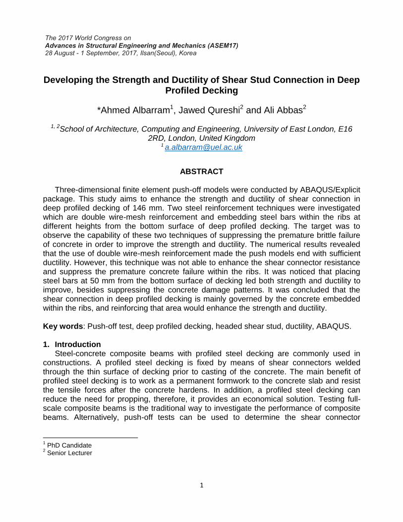
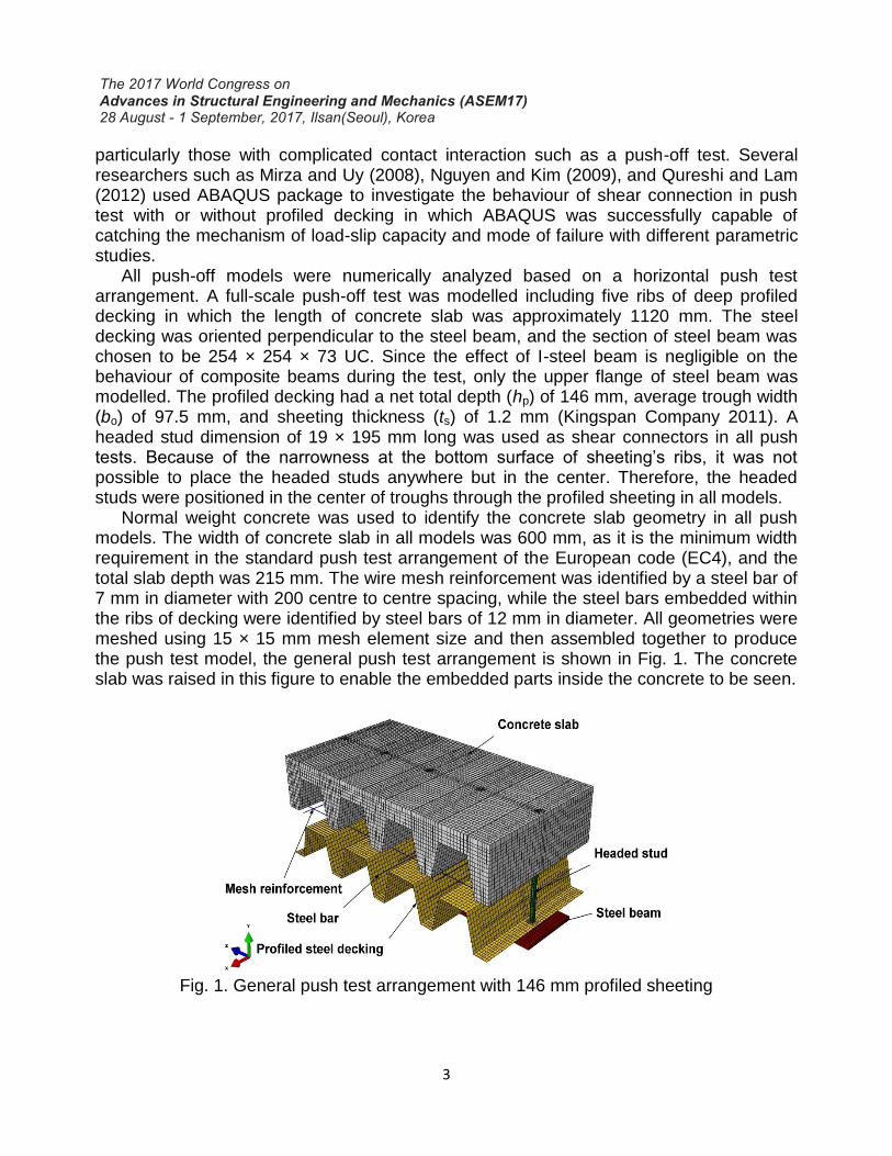
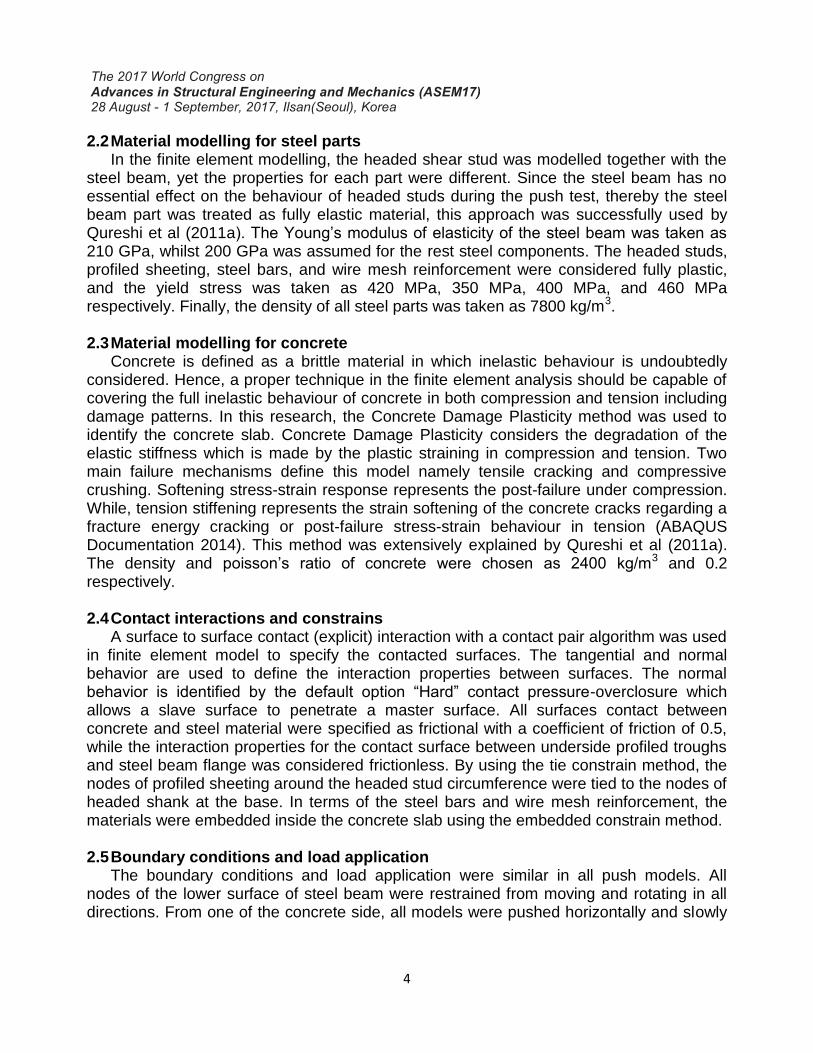
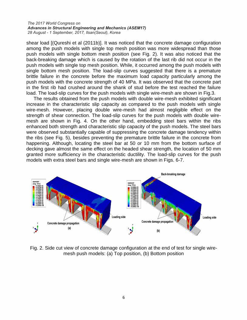
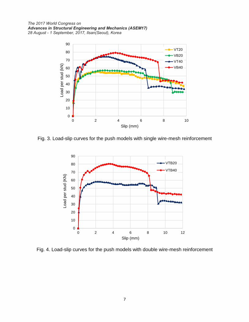
shear load [(Qureshi et al (2011b)]. It was noticed that the concrete damage configuration among the push models with single top mesh position was more widespread than those push models with single bottom mesh position (see Fig. 2). It was also noticed that the back-breaking damage which is caused by the rotation of the last rib did not occur in the push models with single top mesh position. While, it occurred among the push models with single bottom mesh position. The load-slip curves suggested that there is a premature brittle failure in the concrete before the maximum load capacity particularly among the push models with the concrete strength of 40 MPa. It was observed that the concrete part in the first rib had crushed around the shank of stud before the test reached the failure load. The load-slip curves for the push models with single wire-mesh are shown in Fig.3.
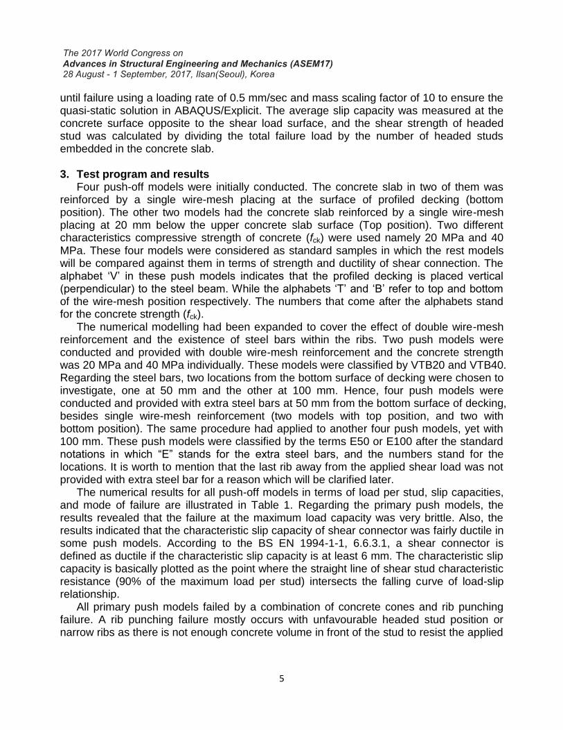
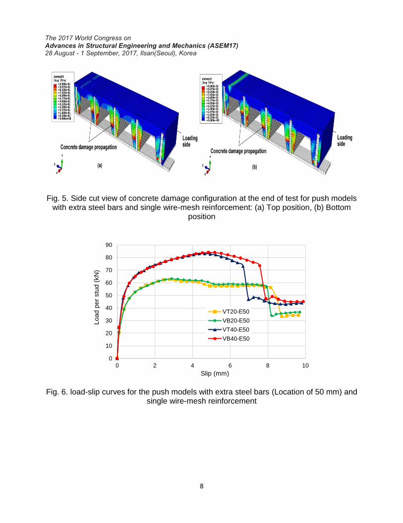
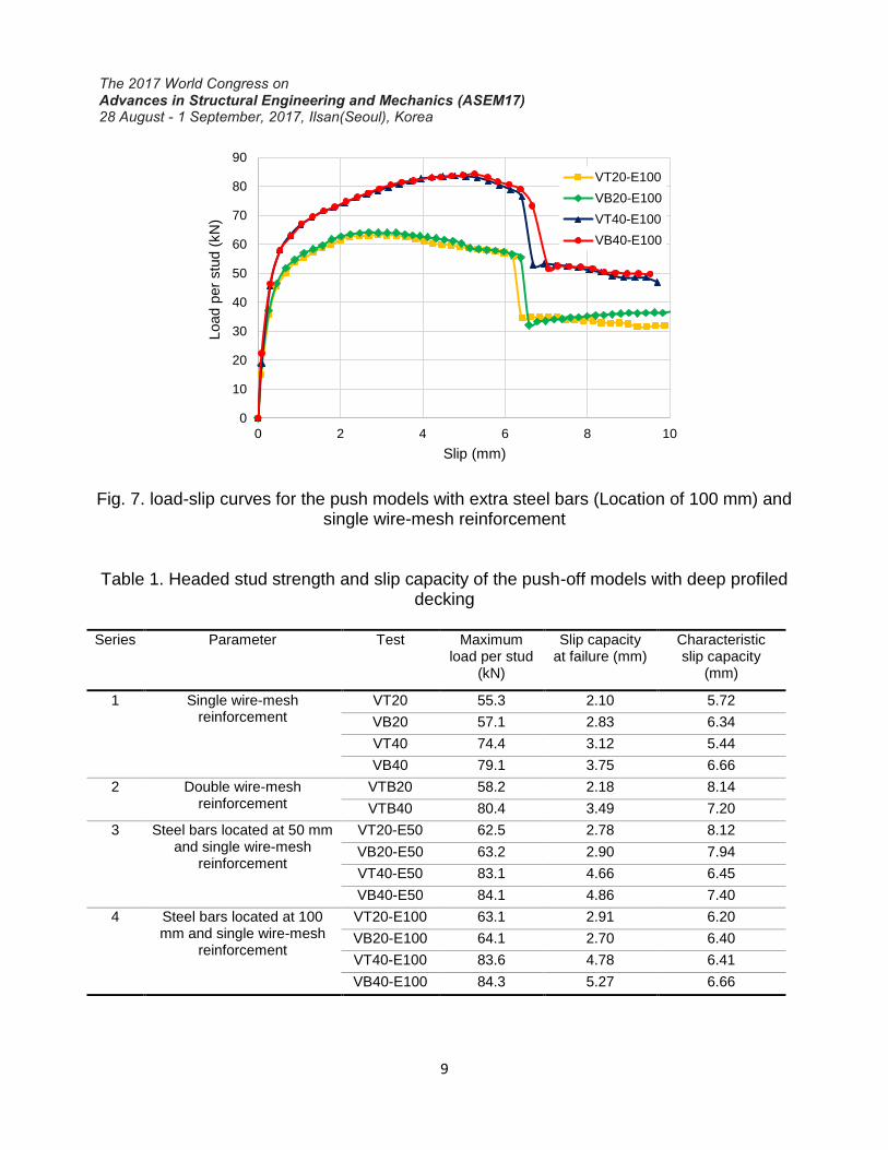
The results obtained from the push models with double wire-mesh exhibited significant increase in the characteristic slip capacity as compared to the push models with single wire-mesh. However, placing double wire-mesh had almost negligible effect on the strength of shear connection. The load-slip curves for the push models with double wire-mesh are shown in Fig. 4. On the other hand, embedding steel bars within the ribs enhanced both strength and characteristic slip capacity of the push models. The steel bars were observed substantially capable of suppressing the concrete damage tendency within the ribs (see Fig. 5), besides preventing the premature brittle failure in the concrete from happening. Although, locating the steel bar at 50 or 10 mm from the bottom surface of decking gave almost the same effect on the headed shear strength, the location of 50 mm granted more sufficiency in the characteristic ductility. The load-slip curves for the push models with extra steel bars and single wire-mesh are shown in Figs. 6-7.
Fig. 2. Side cut view of concrete damage configuration at the end of test for single wire-mesh push models: (a) Top position, (b) Bottom position
7
Fig. 3. Load-slip curves for the push models with single wire-mesh reinforcement
Fig. 4. Load-slip curves for the push models with double wire-mesh reinforcement
0
10
20
30
40
50
60
70
80
90
0 2 4 6 8 10
Load p
er
stu
d (
kN
)
Slip (mm)
VT20
VB20
VT40
VB40
0
10
20
30
40
50
60
70
80
90
0 2 4 6 8 10 12
Load p
er
stu
d (
KN
)
Slip (mm)
VTB20
VTB40
8
Fig. 5. Side cut view of concrete damage configuration at the end of test for push models with extra steel bars and single wire-mesh reinforcement: (a) Top position, (b) Bottom
position
Fig. 6. load-slip curves for the push models with extra steel bars (Location of 50 mm) and single wire-mesh reinforcement
0
10
20
30
40
50
60
70
80
90
0 2 4 6 8 10
Load p
er
stu
d (
kN
)
Slip (mm)
VT20-E50
VB20-E50
VT40-E50
VB40-E50
9
Fig. 7. load-slip curves for the push models with extra steel bars (Location of 100 mm) and single wire-mesh reinforcement
Table 1. Headed stud strength and slip capacity of the push-off models with deep profiled decking
Series Parameter Test Maximum
load per stud (kN)
Slip capacity at failure (mm)
Characteristic slip capacity
(mm)
1 Single wire-mesh reinforcement
VT20 55.3 2.10 5.72
VB20 57.1 2.83 6.34
VT40 74.4 3.12 5.44
VB40 79.1 3.75 6.66
2 Double wire-mesh reinforcement
VTB20 58.2 2.18 8.14
VTB40 80.4 3.49 7.20
3 Steel bars located at 50 mm and single wire-mesh
reinforcement
VT20-E50 62.5 2.78 8.12
VB20-E50 63.2 2.90 7.94
VT40-E50 83.1 4.66 6.45
VB40-E50 84.1 4.86 7.40
4 Steel bars located at 100 mm and single wire-mesh
reinforcement
VT20-E100 63.1 2.91 6.20
VB20-E100 64.1 2.70 6.40
VT40-E100 83.6 4.78 6.41
VB40-E100 84.3 5.27 6.66
0
10
20
30
40
50
60
70
80
90
0 2 4 6 8 10
Load p
er
stu
d (
kN
)
Slip (mm)
VT20-E100
VB20-E100
VT40-E100
VB40-E100
10
4. Discussion The push models with single wire-mesh reinforcement did not experience sufficient
ductility. This is attributed to the premature brittle failure in concrete which was predominant at the early stage of test. It was also apparent that the strength of shear connection was not significantly affected by the position of single wire-mesh. The main difference in the position of single wire-mesh was the back-breaking damage did not occur in the push models with top mesh position, whilst it occurred in the push models with bottom position. This can be explained as placing the wire-mesh close to the upper concrete surface is likely to allow more tensile shear stresses to transfer through the steel reinforcement instead of the concrete. Thus, the top surface of concrete would not crack.
In normal cases, the concrete starts to crush near the head of the shear stud and propagates diagonally toward the corner of the profiled decking (where the web and the upper flange meet) forming the concrete cone failure (Patrick, 2000). However, in the push models with deep profiled decking, the concrete started to crush around the headed studs nearby the bottom surface of decking then propagated upwards, which means the concrete did not start to fail along the assumed concrete failure plane. This is the reason why the function of single wire-mesh reinforcement was ineffective on both strength and ductility of shear connection in deep profiled decking.
The use of double wire-mesh reinforcement made the push models end with sufficient ductility. However, this technique did not enhance the shear connector resistance and suppress the premature concrete failure within the ribs. Hence, it can be concluded that the strength of shear connection in deep profiled decking is not governed by the concrete volume above the surface of decking. The deep profiled decking of 146 mm offers less concrete volume within the ribs when compared to the common multideck depths of 60 mm or 80 mm. The region within the ribs will create a critical zone where the compressive and tensile stresses will concentrate there. Thus, the concrete in that area will experience a premature brittle failure during the test which in turn will reflect on the performance of composite beams in terms of strength and ductility.
The strength and ductility of shear connection developed when steel bars were provided within the ribs. The existence of steel bar in an area where the concrete is likely to crush prevented the premature brittle failure of concrete from happening. Consequently, the concrete embedded within the ribs gained more stiffness at the early stage of test and did not experience a severe damage. Placing steel bars at 50 mm from the bottom surface of decking seemed more effective in ensuring a sufficient ductility than the location of 100 mm. This is because the location of 50 mm is being close to the critical area where the concrete begins to crush. It can be concluded that the shear connection in deep profiled decking is mainly governed by the concrete embedded with the ribs, and reinforcing that area would enhance the strength and ductility.
5. Conclusion
Three-dimensional finite element push-off models with deep profiled decking were conducted by ABAQUS/Explicit. The influence of double wire-mesh reinforcement and placing steel bars at different heights from the bottom surface of decking were investigated.
11
The aim was to observe the ability of different steel reinforcement techniques to improve the behaviour of shear connection in deep profiled decking of 146 mm in terms of strength and ductility. The numerical results indicated that the characteristics ductility were slightly higher than 6 mm in most push models with single wire-mesh reinforcement. The premature brittle failure of concrete was obvious in all primary push models.
The characteristics ductility significantly improved when double wire-mesh reinforcement was used. However, the strength of shear connection did not experience big enhancement and the premature damage of concrete within the ribs was still uncontrollable. It was then concluded that the strength of shear connection in deep profiled decking is not governed by the concrete volume above the upper surface of decking, despite the benefit of double wire-mesh on the ductility. The enhancement in strength and ductility were both achieved when steel bars were embedded within the ribs. It was found that placing steel bars at 50 mm from the bottom surface of decking was more capable than the location of 100 mm of suppressing the brittle damage of concrete and providing a sufficient ductility. It was concluded that the shear connection in deep profiled decking is mainly governed by the concrete embedded with the ribs.
It is recommended that placing steel bars within the ribs of deep profiled decking should be taken into consideration to ensure better performance of shear connection in terms of strength and ductility. Thus, the current design guidance such as the European code (EC4) should be modified if the deep profiled decking of 146 mm is involved.
Acknowledgments
The authors would like to acknowledge the University of East London for their facilities. Also, the first author is sincerely grateful to the Higher Committee for Education Development in Iraq for funding his PhD study.
References ABAQUS Documentation (2014), ABAQUS User’s Manual, Version 6.14, Hibbitt, Karlsson
and Sorenson, USA. ANSI/AISC. (2005). “Specification for Structural Steel Buildings.” ANSI/AISC 360-05,
Chicago, USA. Bradford, M.A., Filonov. A., Hogan, T.J., Uy, B., and Ranzi G. (2006) “Strength and
ductility of shear connection in composite T-beams with trapezoidal steel decking.” The Eight International Conference on Steel, Space and Composite Structures, Kuala Lumpur, Malaysia, 15-26.
Bradford, M.A., Pi, Y.L., and Uy, B. (2008) “Ductility of composite beams with trapezoidal composite slabs.” Proc., Composite Construction in Steel and Concrete VI, American Society of Civil Engineers, Reston, Va., 151-159.
BS EN 1994-1-1, Eurocode 4: Design of composite steel and concrete structures: Part 1.1: General rules and rules for buildings, British Standards Institution, London.
Ernest, S., Bridge, R.Q. and Wheeler, A. (2006) “Correlation of beam tests with pushout tests in steel-concrete composite beams.” Journal of Structural Engineering, Vol. 136(2), 183-192.
12
Ernest, S., Patrick, M., and Wheeler, A. (2004) “Novel shear stud component for secondary composite beams.” Proc., 18th Australian Conference on the Mechanics of Structures and Materials, Balkema, The Netherlands, 63-69.
Kingspan Multideck Technical Handbook (2011), Manufactures of Multideck Composite Metal Decking. North Yorkshire, United Kingdom.
Mirza, O. and Uy, B. (2008) “Behaviour of headed stud shear connectors for composite steel-concrete beams at elevated temperatures.” Journal of Constructional Steel Research, Vol. 65(3), 662-674.
Nguyen, H.T. and Kim, S.E. (2009) “Finite element modeling of push-out tests for large stud shear connectors.” Journal of Constructional Steel Research, Vol. 65(10-11), 1909-1920.
Patrick, M. (2000) “Experimental investigation and design of longitudinal shear reinforcement in composite edge beams.” Progress in Structural Engineering and Materials, Vol. 2(2), 196-217.
Qureshi, J. and Lam, D. (2012) “Behaviour of headed shear stud in composite beams with profiled metal decking.” Advances in Structural Engineering, Vol. 15(9), 1547-1558.
Qureshi, J., Lam, D., and Ye, J. (2011a) “Effect of shear connector spacing and layout on the shear connector capacity in composite beams.” Journal of Constructional Steel Research, Vol. 67(4), 706-719.
Qureshi, J., Lam, D., and Ye, J. (2011b) “The influence of profiled sheeting thickness and shear connector’s position on strength and ductility of headed shear connector.” Journal of Engineering Structures, Vol. 33(5), 1643-1656.