Embed Size (px)
Citation preview
ORIGINAL PAPER
Developing robotic formwork: enhancing formwork mobilityand variability through mechanization
Marcus Shaffer1
Received: 31 December 2016 / Accepted: 4 July 2017! Springer International Publishing AG 2017
Abstract This paper reports on the design and develop-ment of a robotic formwork system for plastic construction
materials. This development applies mechanization and
computational control to the basic concept of formwork,enhancing the qualities of mobility and variability that are
characteristic of contemporary sheet-based formwork sys-
tems. The resulting digi-mechanical ‘‘formwork machine’’could potentially reduce placement, setup, and breakdown
costs and address significant worker safety issues that are
associated with traditional hand-set formwork systems.Robotic formwork could simultaneously enhance the
technology’s unique capacity to respond to architectural
form requirements with increased digitally driven cus-tomization and variability. Contemporary developments in
creating sustainable concrete formwork systems are
working to replace or eliminate sheet-based, hand-setformwork with factory situated alternatives. This project
alternatively keeps formwork onsite, addressing the mate-
rial and economic wastefulness associated with sheet-basedformwork by evolving the current parts-based, disposable
system (sheets/planking, connections, bracing, tie hard-ware, etc.) into a more robust robotic machine. This robotic
formwork can be maintained and used repeatedly—with
the extended durability inherent in construction machi-nes—on pre-mapped construction sites, and/or in con-
struction environments that inhibit or restrict human labor.
Keywords Digi-mechanical formwork machine ! Linkedcasting cartridges ! Radial ! Orthogonal ! Modulated
architectural forms
1 Introduction
The Chinese can be credited with developing the precursor to
our contemporary formwork systems, having devised and
evolved very similar tools/technologies for rammed earthconstruction 2000 years before Roman builders developed
formwork for placing and containing concrete. As concrete
developed into an industrializedconstructionmaterial/processin the middle-1800s, formwork systems evolved in response
to the particularities of concrete building methods, construc-
tion economics, and toward facilitating variations (styles) inarchitectural form. In the last century, parts-based formwork
assemblies were devised to accommodate orthogonal, radial,
and free-form/organic architectural works. During the sameperiod of development, formwork became ‘‘animated’’ to a
certain degree. In response to construction efficiency
requirements and labor costs, large, intact formwork assem-blies on rollers could bemovedaroundconcrete constructions,
‘‘jack’’ up and down vertically, ‘‘climb’’ sequentially pouredwalls, and ‘‘fly’’ from one completed level of construction to
the next aided by cranes (Hanna 1998). These emergent
qualities of variability andmobility havepositioned formworkassemblies to become mechanized and automated—for the
development of programmed formwork assemblies that can
be remotely deployed, positioned, set up, receive liquidmaterials, break apart from the resultant construction, and
repeat—in a manner that is at least semi-automated.
State-of-the-art developments around concrete formworktechnologies, however, are currently focused on issues related
to sustainability; eliminating the material wastes that are
& Marcus [email protected]
1 Department of Architecture, The Pennsylvania StateUniversity, 224 Stuckeman Family Building, Penn StateArchitecture, University Park, PA 16802, USA
123
Constr Robot
DOI 10.1007/s41693-017-0004-4
inherent in its use. Industry estimates from 2008 determined
that 35–60% of concrete architecture construction costs arededicated to the fabrication, erection, tear-down, and disposal
of formwork (Orr et al. 2012). New developments along these
lines—including re-usable wax formwork (Orr et al. 2012),and a variety of formwork-free robotic placement methods
(De Kestelier and Buswell 2012)—typically move concrete
construction off-site, into factory-like fabrication facilitieswhere standards of control, worker safety, and production are
significantly better, and more consistent, than those foundonsite. The trade-offs associated with these methods of con-
crete construction include size andweight limitations imposed
by transport, transportation costs, and increased pollutionassociated with transport. Additionally, assembling concrete
building elements—rather than placing concrete in formwork
onsite—creates buildings that are essentially parts-builthybrids: combinations of reinforced concrete elements, steel
structures, hardware, liquid sealants, and veneers.
Alternatively, other construction technologies, namely steeland brickmasonry, have delivered similarly improved levels of
production, production quality, safety, and sustainable prac-
tices directly to the construction site through robotic enhance-ment. In the 1980s, Japanese industries began exploring the
potential of robotic construction in response to stagnation and
inefficiencies resultant from the following factors (as articu-lated by Boch): a lack of skilled construction labor, poor con-
struction site safety conditions,monotony/repetition inherent in
construction work, low production quality, time waste andscheduling delays, environmental damage, and high construc-
tion costs (Bock 2009). Ultimately, this industrial explo-
ration—extended beyond Japanese industries over the past30 years—resulted in the development of robotic masonry
construction technologies. Swiss architects Gramazio and
Kohler developed their R-O-B in 2007, and the S.A.M. (semi-automated mason) brick-laying robot, developed and currently
in use by New York-based Construction Robotics, claims to
produce high-quality masonry three times faster than a humanmason (Gramazio and Kohler 2008).
The purpose of this research is to enhance the charac-
teristics of mobility and variability that have emerged informwork systems development—through robotization. In
developing a digi-mechanical formwork, there is also the
potential to address limiting factors in contemporary hand-set formwork systems: specifically, material and labor
resources, worker safety, time inefficiencies, and long-term
environmental concerns.
2 Machine development
This paper details the development of roboticized form-
work through scale models and full-scale prototyping,roughly outlined in three groupings: hinged plates, linked
cartridges (soft gasket), and linked cartridges (hard gasket).
All of the models and prototypes depicted in this paper are‘‘functional’’, in that they can be manipulated and loaded
with plastic materials. Each prototype in the development
informed the design of a subsequent prototype. This paperprimarily addresses hardware development—making a
casting surface that can move and change shape—with less
focus on control/code, and/or plastic material development.
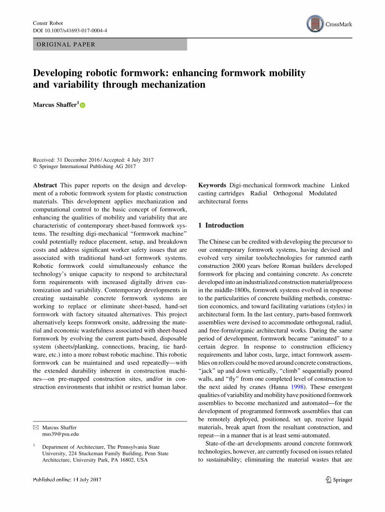
2.1 Prototype 01(hinged plates)
This proposal began with an analog prototype consisting of
a chain of 9.600 9 9.600 casting plates hinged together andsupported by a simple drive mechanism (Fig. 1).
This initial formwork could be manipulated with a hand
drill to produce linear/right-angled and radial forms. In thefinal test of this prototype, a large arch was configured,
reinforcing bars were placed in the formwork, the open
ends of the formwork were boarded up, and it was loadedwith concrete through the apex of the arch. After the
concrete hydrated and hardened sufficiently, the battens
were removed and prototype 01 was manipulated so as tobreak away from the resultant arch. In this process, it
became evident that an automated variable formwork had
real potential. It also became evident that robotic formworkcould be designed and programmed to move itself through
the various processes associated with pouring concrete
Fig. 1 Hinged casting plates (top) set in parallel chains to form linearand radial concrete forms (below)
Constr Robot
123
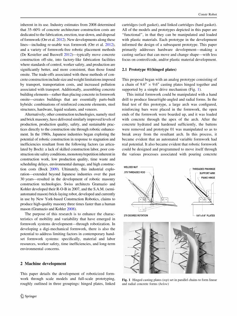
(Fig. 2). One significant drawback identified in prototype
01 was the fact that it could only produce extruded forms.
This limitation became the basis for evolving the castingsurface beyond flat plates, into thicker bodied ‘‘casting
cartridges’’ during the next stage of prototyping.
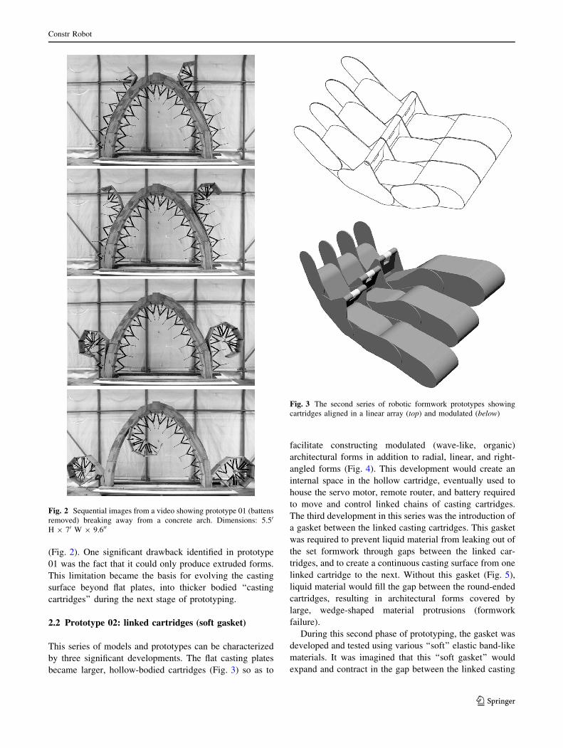
2.2 Prototype 02: linked cartridges (soft gasket)
This series of models and prototypes can be characterizedby three significant developments. The flat casting plates
became larger, hollow-bodied cartridges (Fig. 3) so as to
facilitate constructing modulated (wave-like, organic)architectural forms in addition to radial, linear, and right-
angled forms (Fig. 4). This development would create an
internal space in the hollow cartridge, eventually used tohouse the servo motor, remote router, and battery required
to move and control linked chains of casting cartridges.
The third development in this series was the introduction ofa gasket between the linked casting cartridges. This gasket
was required to prevent liquid material from leaking out of
the set formwork through gaps between the linked car-tridges, and to create a continuous casting surface from one
linked cartridge to the next. Without this gasket (Fig. 5),
liquid material would fill the gap between the round-endedcartridges, resulting in architectural forms covered by
large, wedge-shaped material protrusions (formwork
failure).During this second phase of prototyping, the gasket was
developed and tested using various ‘‘soft’’ elastic band-like
materials. It was imagined that this ‘‘soft gasket’’ wouldexpand and contract in the gap between the linked casting
Fig. 2 Sequential images from a video showing prototype 01 (battensremoved) breaking away from a concrete arch. Dimensions: 5.50
H 9 70 W 9 9.600
Fig. 3 The second series of robotic formwork prototypes showingcartridges aligned in a linear array (top) and modulated (below)
Constr Robot
123
cartridges as they moved/set up to receive liquid materials.Testing through two rounds of quarter-scale models loaded
with plaster proved that these chains of linked cartridges
could facilitate a wider variety of architectural forms thanprototype 01 and function as formwork in making basic
architectural elements such as walls (Fig. 6). These same
tests also showed that employing the soft gasket would beproblematic and unreliable. The soft gasket was difficult to
tension properly between the variably positioned linked
cartridges—in modeling, it either became trapped in thehardened material or failed to prevent the liquid material
from flooding into the gap. Solving this problem became
the primary focus while developing the third series ofmodels and prototypes.
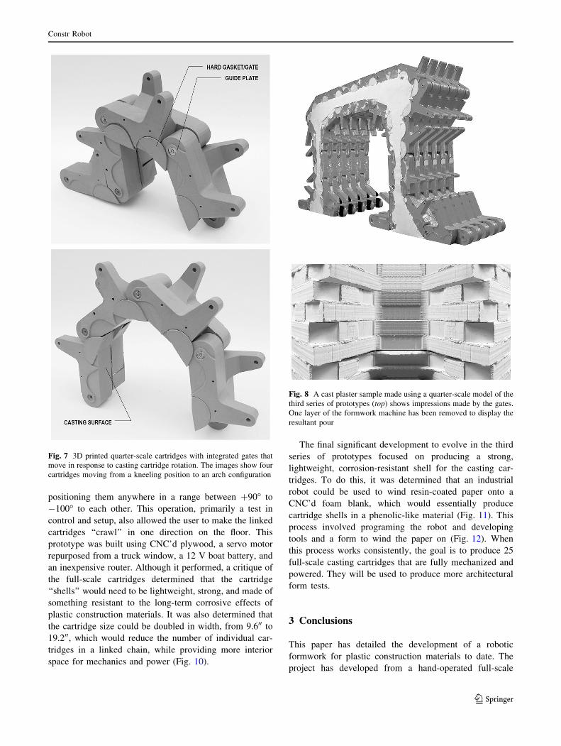
2.3 Prototype 03: linked cartridges (hard gasket)
The third series of prototypes made in developing a
roboticized formwork evolved and improved the projectthrough several design modifications.
The first significant development was the design and
testing of a ‘‘hard gasket’’ or ‘‘gate’’ that replaced the soft
gasket between casting cartridges in prototype 02 (Fig. 7).
These gates open and close in response to the rotational
movement of neighboring cartridges in a chained sequence.Each gate closes the gap between linked casting cartridges,
with its overlapping edge controlled by a protruding guide
plate designed into the face of each (neighboring) cartridge.The gate is activated by cartridge rotation and facilitated by a
spring-loaded axle housed inside the casting cartridge. An
immediate consequence of integrating these hard gates intothe cartridge-based formwork is that they produce ‘‘knuck-
led’’ impressions in corner castings (Fig. 8).
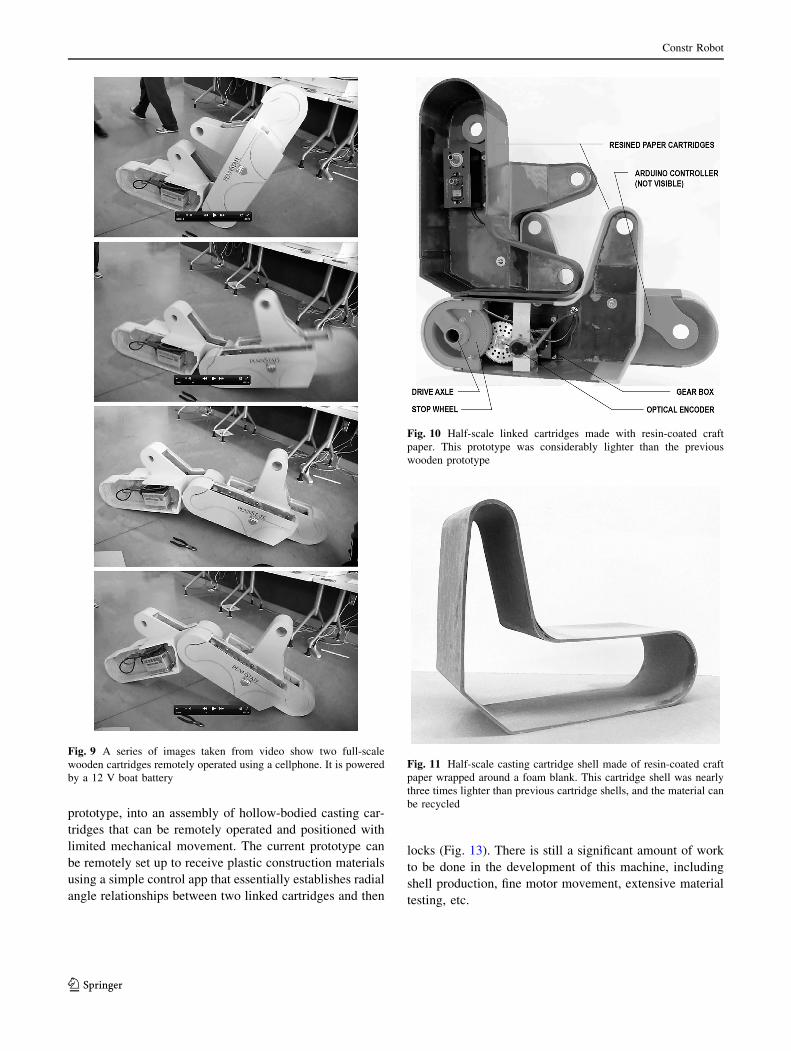
The second significant development during this phase oftesting and prototyping is connected to the fabrication of
two full-scale linked cartridges equipped with a servo
motor, battery, and a remote router (Fig. 9). The cartridgeswere operated using a purpose-built control app on a
mobile phone. The app essentially allowed the user to
rotate the two linked cartridges using a slider/track bar,
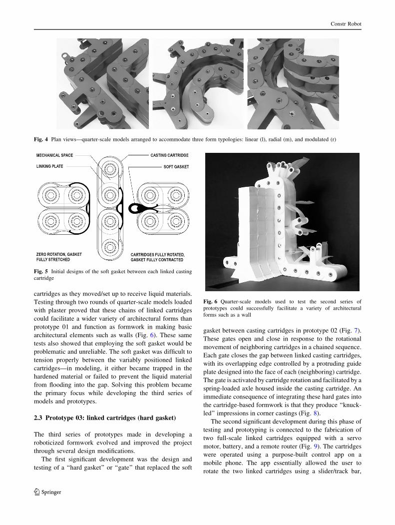
Fig. 4 Plan views—quarter-scale models arranged to accommodate three form typologies: linear (l), radial (m), and modulated (r)
Fig. 5 Initial designs of the soft gasket between each linked castingcartridge
Fig. 6 Quarter-scale models used to test the second series ofprototypes could successfully facilitate a variety of architecturalforms such as a wall
Constr Robot
123
positioning them anywhere in a range between ?90" to
-100" to each other. This operation, primarily a test in
control and setup, also allowed the user to make the linkedcartridges ‘‘crawl’’ in one direction on the floor. This
prototype was built using CNC’d plywood, a servo motor
repurposed from a truck window, a 12 V boat battery, andan inexpensive router. Although it performed, a critique of
the full-scale cartridges determined that the cartridge
‘‘shells’’ would need to be lightweight, strong, and made ofsomething resistant to the long-term corrosive effects of
plastic construction materials. It was also determined that
the cartridge size could be doubled in width, from 9.600 to19.200, which would reduce the number of individual car-
tridges in a linked chain, while providing more interior
space for mechanics and power (Fig. 10).
The final significant development to evolve in the third
series of prototypes focused on producing a strong,lightweight, corrosion-resistant shell for the casting car-
tridges. To do this, it was determined that an industrial
robot could be used to wind resin-coated paper onto aCNC’d foam blank, which would essentially produce
cartridge shells in a phenolic-like material (Fig. 11). This
process involved programing the robot and developingtools and a form to wind the paper on (Fig. 12). When
this process works consistently, the goal is to produce 25
full-scale casting cartridges that are fully mechanized andpowered. They will be used to produce more architectural
form tests.
3 Conclusions
This paper has detailed the development of a robotic
formwork for plastic construction materials to date. Theproject has developed from a hand-operated full-scale
Fig. 7 3D printed quarter-scale cartridges with integrated gates thatmove in response to casting cartridge rotation. The images show fourcartridges moving from a kneeling position to an arch configuration
Fig. 8 A cast plaster sample made using a quarter-scale model of thethird series of prototypes (top) shows impressions made by the gates.One layer of the formwork machine has been removed to display theresultant pour
Constr Robot
123
prototype, into an assembly of hollow-bodied casting car-tridges that can be remotely operated and positioned with
limited mechanical movement. The current prototype can
be remotely set up to receive plastic construction materialsusing a simple control app that essentially establishes radial
angle relationships between two linked cartridges and then
locks (Fig. 13). There is still a significant amount of work
to be done in the development of this machine, includingshell production, fine motor movement, extensive material
testing, etc.
Fig. 9 A series of images taken from video show two full-scalewooden cartridges remotely operated using a cellphone. It is poweredby a 12 V boat battery
Fig. 10 Half-scale linked cartridges made with resin-coated craftpaper. This prototype was considerably lighter than the previouswooden prototype
Fig. 11 Half-scale casting cartridge shell made of resin-coated craftpaper wrapped around a foam blank. This cartridge shell was nearlythree times lighter than previous cartridge shells, and the material canbe recycled
Constr Robot
123
Ultimately, this robotic formwork would give a con-structor the ability to remotely place and set up durable
formwork to receive plastic construction materials and to
accommodate a variety of architectural forms.
Acknowledgements The author would like to thank and acknowl-edge the following people who have committed time and knowledgeto this project: the team of Dan White, Kishan Patel, and ConnorDalay—who worked so diligently in developing the ‘‘action axle’’ andrelated programming; Shokofeh Darbari, Justin Teufel, Seth Wald-man, and Steve White, who assisted in developing tools and pro-gramming for the industrial robot; and Zijing Shang, who assisted in3D printing models.
References
Bock T (2009) Turning points in construction. In: Proceedings of the2009 26th international symposium on automation and roboticsin construction. I.A.A.R.C., Austin, pp. 3–9
De Kestelier X, Buswell R (2012) Large-scale additive fabrication.In: Sheil B (ed) Manufacturing the bespoke. Wiley, London,pp 249–255
Gramazio F, Kohler M (2008) Digital materiality in architecture. LarsMuller Publishers, Baden
Hanna Awad S (1998) Concrete formwork systems. Taylor andFrancis, New York
Orr J, Evernden M, Darby A, Ibell T (2012) Proceedings of thesecond international conference on flexible formwork. BRECICM, University of Bath
Fig. 12 A series of images taken from video show an industrial robotwinding (dry) paper around a cartridge-shaped form
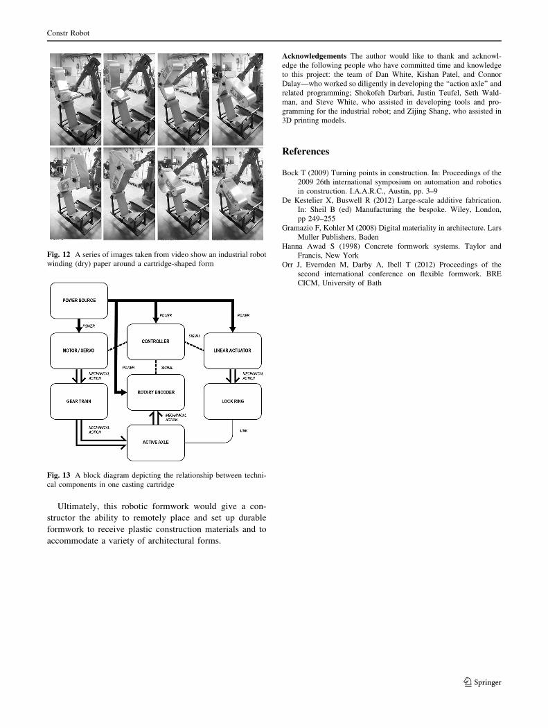
Fig. 13 A block diagram depicting the relationship between techni-cal components in one casting cartridge
Constr Robot
123