Embed Size (px)
Citation preview

Developing Plug-ins inMax/MSP for
pluggoUPDATED INFORMATION FOR PLUGGO 3
revision 4 of 16 May 2002
2 Developing Plug-ins for Pluggo
Copyright and Trademark Notices
pluggo, Plug-in Manager, and this manual are copyright © 2000-2002 Cycling ’74.
pluggo, Plug-in Manager, and MSP are trademarks of Cycling ’74. Max, Vision, Vision DSP, andStudio Vision are trademarks of Opcode Systems, Inc. VST and Cubase are trademarks ofSteinberg Soft- und Hardware GmbH. Pro Tools and RTAS are trademarks of Digidesign, adivision of Avid Technology.
Credits
Runtime plug-in environment and development documentation: David Zicarelli
Plug-ins and Support Objects: jhno, Adam Schabtach, Joshua Kit Clayton, Les Stuck, RichardDudas, David Zicarelli, Marc Sirguy, Darwin Grosse. Essential Instruments designed by eowave.
Graphic Design: jhno, Lilli Hart, Adam Schabtach
pluggo Character: Richard Dudas
Contents
Developing Plug-ins for Pluggo 3
Introduction...................................................................................................... 6Plug-in Development ................................................................................................. 6
How This Manual Is Organized ................................................................................. 6
About VST Plug-ins ................................................................................................... 6
Parameters ................................................................................................................. 7
Programs.................................................................................................................... 7
User Interfaces ........................................................................................................... 8
Developing and Testing Plug-ins ............................................................................... 11
What Plug-ins Can and Can’t Do............................................................................... 12
Tutorial P1 ....................................................................................................... 14Plug-in Inputs and Outputs ....................................................................................... 14
Defining Plug-in Parameters ...................................................................................... 15
Using Plugmaker ........................................................................................................ 16
Tutorial P2 ....................................................................................................... 19Improving the User Experience ................................................................................. 19
Making Effect Programs............................................................................................. 19
Adding Descriptive Information to Parameters......................................................... 21
Adding a Plug-in About Box ...................................................................................... 22
Tutorial P3 ....................................................................................................... 24The Wonders of Modulated Interpolating Delay Lines.............................................. 24
A Plug-in User Interface in Max................................................................................. 25
Tutorial P4 ....................................................................................................... 28Collections of Parameters........................................................................................... 28
Tutorial P5 ....................................................................................................... 31Parameter Modulation............................................................................................... 31
The plugmod Object .................................................................................................. 31
Generating Modulation Information ......................................................................... 33
Tutorial P6 ....................................................................................................... 35Utilizing Host Syncronization Information ............................................................... 35
Using plugsync~ ........................................................................................................ 35
Trying the Patch ......................................................................................................... 36
Beat Information ........................................................................................................ 37
Contents
4 Developing Plug-ins for Pluggo
Tutorial P7 ....................................................................................................... 38Audio Rate Pan .......................................................................................................... 38
Using plugphasor~ and rate~ .................................................................................... 38
Tutorial P8 ....................................................................................................... 40A Really Simple Synthesizer ....................................................................................... 40
Interpreting MIDI...................................................................................................... 40
Attack-Decay-Release Envelope ................................................................................ 41
plugconfig synth......................................................................................................... 43
Trying the Synth as a Plug-in...................................................................................... 43
Tutorial P9 ....................................................................................................... 44A MIDI processor ...................................................................................................... 44
Changing Note Data .................................................................................................. 44
Trying the Transformer in Digital Performer............................................................. 46
Other Ideas................................................................................................................. 48
Tutorial P10 ..................................................................................................... 49Morphing................................................................................................................... 49
Testing It Out ............................................................................................................. 49
How It Works ............................................................................................................ 49
Conclusion................................................................................................................. 51
Plugmaker........................................................................................................ 52Introduction............................................................................................................... 52
Using Plugmaker ........................................................................................................ 52
Plug-in Names ........................................................................................................... 52
Parameter Analysis..................................................................................................... 52
Plugmaker.nostrip ..................................................................................................... 53
Plugmaker.vmresources............................................................................................. 53
Updating Old Plug-ins ............................................................................................... 53
Conventions ..................................................................................................... 54PluggoSync ................................................................................................................ 54
PluggoBus .................................................................................................................. 55
Runtime Issues ................................................................................................. 57User Interface Limitations.......................................................................................... 57
Audio Processing ....................................................................................................... 57

Contents
Developing Plug-ins for Pluggo 5
Initialization ............................................................................................................... 57
The Max Window ...................................................................................................... 58
Multiple Plug-in Issues .............................................................................................. 58
Priority Level Concerns.............................................................................................. 58
Discontinuous DSP Networks ................................................................................... 60
Collectives .................................................................................................................. 61
Appendix A ...................................................................................................... 62Objects Not Functional .............................................................................................. 62
External Object Support Functions Not Available ..................................................... 62
Index ............................................................................................................... 64
Introduction
6 Developing Plug-ins for Pluggo
Plug-in Development
This manual describes how to use the audio plug-in construction tools in Max/MSP. Thesetools consist of nine Max/MSP objects, an application called Plugmaker, and a shell, which wecall pluggo that loads plug-ins built in Max/MSP and creates an interface for them that appears toa host audio program as an audio plug-in. In this manual, we refer to the pluggo shell as theruntime plug-in environment and the audio program that can make use of pluggo as the host mixeror host sequencer.
pluggo can be downloaded from the Cycling ’74 web site www.cycling74.com. Demo versions ofpopular sequencing applications such as Cubase, Logic Audio, Pro Tools, and Digital Performercan be obtained—with varying degrees of difficulty—from their publishers and distributors.Max/MSP can also be used as a host environment for plug-ins developed in Max/MSP using thevst~ object.
The runtime plug-in environment currently runs under RTAS, MAS, and VST hostenvironments and provides platform-independence so Max/MSP developers may write a singleplug-in that works under all supported environments.
How This Manual Is Organized
This manual assumes familiarity with pluggo as well as Max/MSP. Before developing your ownplug-ins, we think it’s useful to see what has already been done so if you haven’t tried out thecollection of plug-ins included with pluggo, we recommend doing so before reading any further.
After this brief introductory chapter, we present a number of Tutorials that will serve as anintroduction to developing plug-ins using Max/MSP. These tutorials cover the process ofconstructing Max patches that will work as plug-ins, and they assume you’re familiar withprogramming in Max and MSP. After the tutorials, we briefly discuss the Plugmaker applicationthat transforms Max patcher files into VST plug-in files.
Reference pages for the objects used in constructing plug-ins can be found in the MSP manual.
We next present information about two evolving “conventions” adopted by the plug-insincluded with pluggo, a synchronization scheme called PluggoSync and an inter plug-in audiocommunication scheme called the PluggoBus. By conforming to these standards, you cansynchronize your plug-in to the tempo of the music and allow it to send and receive audiosignals.
The last chapter of the manual describes differences between Max and the runtime plug-inenvironment that you should take into account when designing your plug-in patcher.
About VST Plug-ins
The plug-in development model most closely follows the VST plug-in specification developedby Steinberg Soft- und Hardware GmbH. It is available from the Steinberg web sitewww.steinberg.net or www.steinberg.de. You won’t need to know anything about the
Introduction
Developing Plug-ins for Pluggo 7
specification in order to develop plug-ins using Max/MSP, but it’s helpful to be familiar with afew basic elements of plug-in jargon. VST defines a standard for plug-ins that process audio inreal time. Most of the programs that currently host VST plug-ins are audio sequencers similar toCubase, the first program that hosted the plug-ins, although this may not necessarily be true inthe future.
The other plug-in formats, RTAS and MAS, are very similar to VST, and we've made it so youwon't have to know anything about the details of each format. Therefore, in the discussion thatfollows, we will not need to make reference to any specific plug-in format.
Plug-ins have a process routine. This is the DSP code that transforms boring audio on input intoaudio output so wonderful you think people will pay for it. You can “construct” this routineusing MSP audio objects, along with two special objects (plugin~ and plugout~) that define theaudio signal interface between your MSP patch and the plug-in’s host. We’ll talk more aboutplugin~ and plugout~ in the first Tutorial chapter. Max/MSP also allows you to build plug-insthat don’t process audio at all, but instead use the control features of Max to modulate theparameters of other plug-ins. These plug-ins are known as modulators and are discussed inTutorial P5.
Parameters
Almost all plug-ins also have parameters. These are named values that the host application canchange via automation or with its default interface that assigns a slider or knob to eachparameter. If you make a plug-in that opens its own edit window, it is responsible for displayingand editing any parameters it has. The Max/MSP environment can build a standard “egg slider”parameter interface for you. Parameters are changed while the audio processing routine isrunning, so you get immediate feedback on the effect of a parameter change. When a plug-inloads, it tells its host how many parameters it has. This value cannot change during the life of aplug-in.
Programs
Plug-ins can store a collection of parameter settings called a program (we’ll refer to these as effectprograms in this manual to distinguish them from the many other meanings of the word“program”). Among popular host sequencer/mixer environments, VST hosts Cubase and LogicAudio provide users with the ability to use effect programs stored within the plug-in. DigitalPerformer (using MAS 2.0 or later) allow for presets that are stored outside of the plug-in,unlike VST effect programs whose contents is the plug-in’s responsibility. Pro Tools behavessimilarly to Digital Performer.
When a VST plug-in loads, it tells the host mixer how many effect programs it has. The plug-initself is responsible for storing its own effect programs, and all of the plug-in’s effect programsmust have the same number of parameters. In MAS and RTAS, the effect programs are exportedto the host when the plug-in loads, and the host stores the information. Effect programs alsohave names. As you’ll see in Tutorial P2, the plugconfig object allows you to store named effectprograms full of parameter values within your patcher. This provides a way give the user a tasteof what your plug-in can do. There is no way for a user to modify permanently the contents of
Introduction
8 Developing Plug-ins for Pluggo
the effect program data within a plug-in. However, the parameter changes of all effect programsare typically saved in host sequencer documents. What’s more, most hosts have the ability toload and save files of effect programs.
When a parameter in a plug-in is changed, the change is stored directly into the current effectprogram. Unlike a typical MIDI synth or effects unit, there is no “edit buffer.” At least that’s theway the original VST plug-ins behaved, so that’s now what users expect. In any case, the storageand recall of programs and parameters is not something you need to worry about. The runtimeplug-in environment handles it all for you as long as you use the parameter definition objects ppand plugmultiparam. In MAS and RTAS, there is effectively an edit buffer the host writes over itwhen new effect programs are chosen.
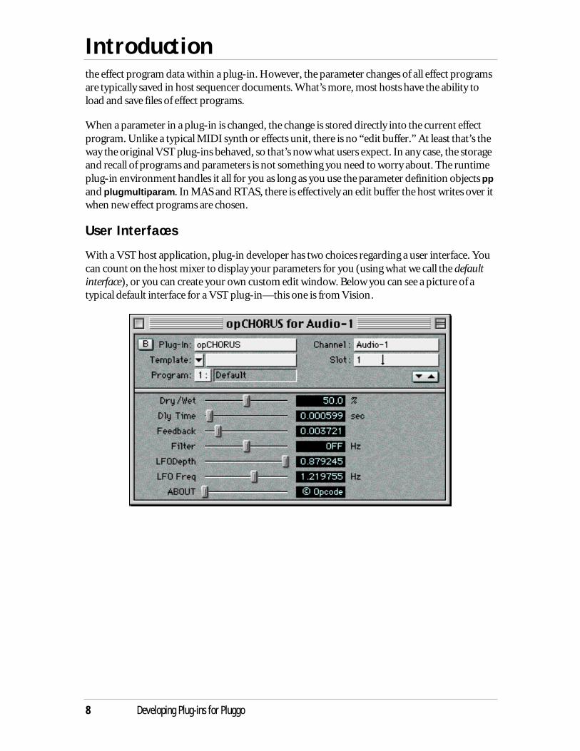
User Interfaces
With a VST host application, plug-in developer has two choices regarding a user interface. Youcan count on the host mixer to display your parameters for you (using what we call the defaultinterface), or you can create your own custom edit window. Below you can see a picture of atypical default interface for a VST plug-in—this one is from Vision.

Introduction
Developing Plug-ins for Pluggo 9
Here is an example of a plug-in from Steinberg that has a custom edit window.
Introduction
10 Developing Plug-ins for Pluggo
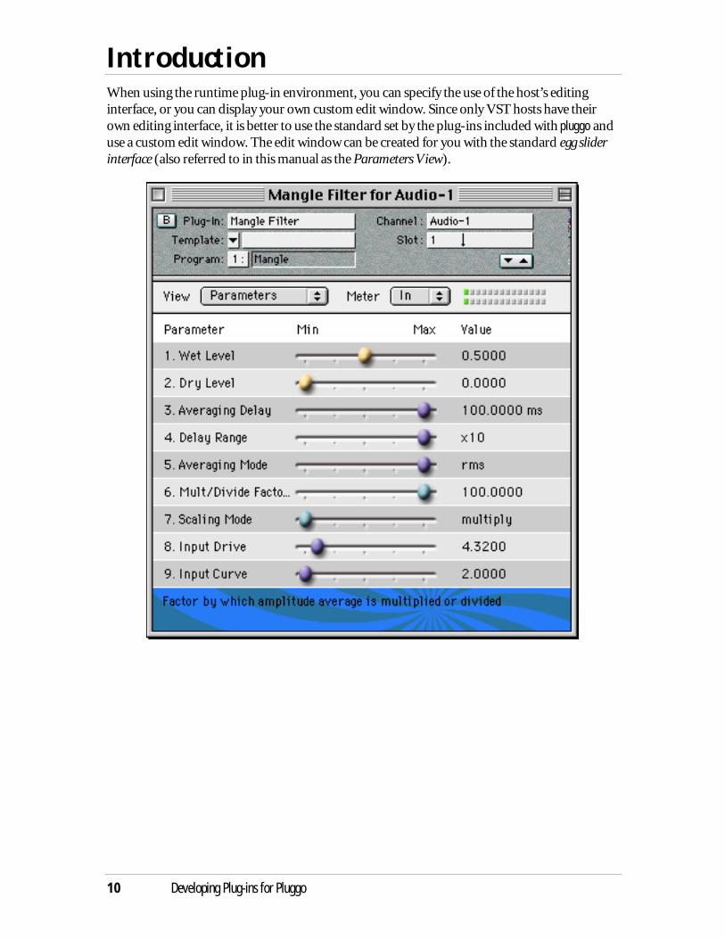
When using the runtime plug-in environment, you can specify the use of the host’s editinginterface, or you can display your own custom edit window. Since only VST hosts have theirown editing interface, it is better to use the standard set by the plug-ins included with pluggo anduse a custom edit window. The edit window can be created for you with the standard egg sliderinterface (also referred to in this manual as the Parameters View).
Introduction
Developing Plug-ins for Pluggo 11
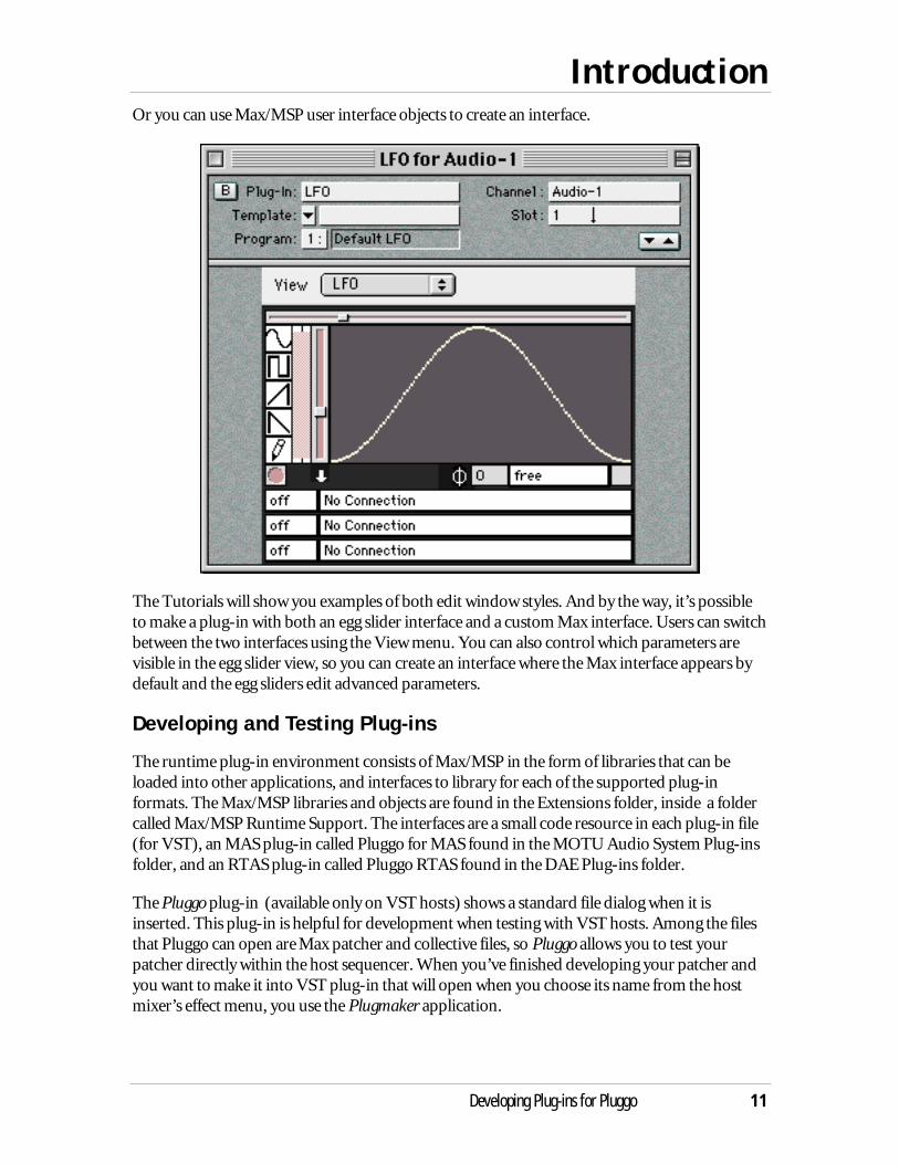
Or you can use Max/MSP user interface objects to create an interface.
The Tutorials will show you examples of both edit window styles. And by the way, it’s possibleto make a plug-in with both an egg slider interface and a custom Max interface. Users can switchbetween the two interfaces using the View menu. You can also control which parameters arevisible in the egg slider view, so you can create an interface where the Max interface appears bydefault and the egg sliders edit advanced parameters.
Developing and Testing Plug-ins
The runtime plug-in environment consists of Max/MSP in the form of libraries that can beloaded into other applications, and interfaces to library for each of the supported plug-informats. The Max/MSP libraries and objects are found in the Extensions folder, inside a foldercalled Max/MSP Runtime Support. The interfaces are a small code resource in each plug-in file(for VST), an MAS plug-in called Pluggo for MAS found in the MOTU Audio System Plug-insfolder, and an RTAS plug-in called Pluggo RTAS found in the DAE Plug-ins folder.
The Pluggo plug-in (available only on VST hosts) shows a standard file dialog when it isinserted. This plug-in is helpful for development when testing with VST hosts. Among the filesthat Pluggo can open are Max patcher and collective files, so Pluggo allows you to test yourpatcher directly within the host sequencer. When you’ve finished developing your patcher andyou want to make it into VST plug-in that will open when you choose its name from the hostmixer’s effect menu, you use the Plugmaker application.
Introduction
12 Developing Plug-ins for Pluggo
A plug-in made with Plugmaker contains the same code resource as the Pluggo plug-in(although it has been renamed from “Pluggo” to the name of the patcher or collective file thatwas given to Plugmaker). This resource is of the type that a VST plug-in host expects to load—it’s Macintosh resource code is ‘aEff’ (for “audio effect”). In a Plugmade plug-in, the code in theaEff resource notices a patcher in the file and tells the runtime environment to load the patcherinside the plug-in file rather than ask the user for a file.
When testing under MAS, it is not necessary to use the Pluggo plug-in to load Max patcher files.Instead, you can simply drag these files to the VstPlugIns folder found within the MAS clientapplication’s folder. Then either restart the client application, or, in Digital Performer, chooseMIDI Only from the Audio System submenu of the Basics menu. Then choose MOTU AudioSystem from this same menu, and the list of plug-ins will be updated.
When testing under RTAS, place your plug-in into the Pluggo Plug-ins folder inside the ProTools application folder. It must be turned into a plug-in using Plugmaker before you can use itin Pro Tools.
What Plug-ins Can and Can’t Do
You’ll find that most everything about the runtime behavior of your plug-in patcher within Maxwill carry over into the plug-in environment. Your patcher interface will operate as you expect itto and most (but not all, see Appendix A) Max objects and capabilities are available to you.However, a plug-in is a guest in someone else’s house, and there are definite restrictions in thearea of user interface, file loading, and initialization that are mandated by the need to adhere tothe standards of the various host applications.
One major difference between a patcher running in Max/MSP and one running in the runtimeplug-in environment is that while you will probably want to maintain the individuality of yourplug-in patcher, all the plug-in patchers are loaded within the same runtime space. As anexample, if you want to send control data between one plug-in and another, you can use thesend and receive objects. But if you want to use these objects and not make your datapotentially available to other plug-ins, you’ll have to use special symbols that create privatecommunication channels within a plug-in patcher.
A major difference between MSP within Max and the runtime plug-in environment is that eachplug-in has its own DSP chain—the sequence of calls made for each block of samples that definethe signal processing algorithm. By contrast, in Max, all signal objects in all patchers currently inmemory share a single DSP chain (unless you are using the poly~ or pfft~ objects).
Please refer to the Runtime Issues chapter for more detailed information on these and otherdifferences between Max and the runtime plug-in environment.
An audio plug-in has a highly restricted world view. It is passed input and output vectors ofsamples, and must process the input vectors and copy the result to the output vectors. Typically,plug-ins are used for filters, compressors, delays, and reverbs. Users probably expect that whatyou develop will be used to enhance some other source material that’s already been recorded, soit's unclear whether sequencer users are going to appreciate a plug-in that ignores its input,
Introduction
Developing Plug-ins for Pluggo 13
producing unrelated output. But you may not care what others will appreciate. The VST 2.0,RTAS, and MAS standards allow plug-ins that can receive MIDI information and produceaudio output from it (i.e., synthesizers). In Cubase 4.1, these plug-ins are referred to as VSTInstruments. (VSTi is also a commonly used shorthand.)
But if audio is not what you want to process, it’s OK to make a plug-in that contains no MSPsignal objects at all. When the run-time plug-in environment notices there is no DSP chain afterloading a patcher, it runs a default processing routine that simply echoes (or adds) the audioinput to the audio output. You’ll see why you would want to make a non-audio effect in TutorialP5.
Among others, the MIDI objects in Max are not available in the runtime plug-in environment.In VST 2.0 and MAS, MIDI input and output to and from the host is possible and the specialobjects plugmidiin and plugmidiout are used for this purpose. RTAS has MIDI input usingplugmidiin only. These objects do nothing in a host environment not capable of sending MIDIto and/or from plug-ins. Appendix A lists the complete set of kernel objects and supportfunctions that are not supported.
Another major restriction of the runtime plug-in environment is that since the VST 1.0standard only allows a single fixed-size window for the user interface, opening more than onewindow is not allowed. It’s even dangerous to open a dialog box. The environment does supportscrolling the patcher window to set positions, called views, that the user can select using either apop-up menu above the interface or via some control within the interface itself.

Tutorial P1 A plug-in with an egg slider interface
14 Developing Plug-ins for Pluggo
In this tutorial, we will look at a simple delay line that uses the runtime plug-in environment’sParameters view in its edit window.
Open the file called Tutorial P1 in the Development Materials folder inside the Pluggo Stufffolder.
Plug-in Inputs and Outputs
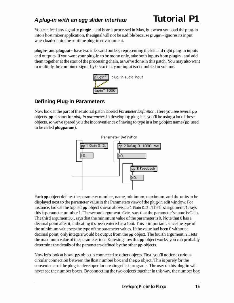
Let’s look first at the part of the patcher labeled Signal Network. Turn on the audio by clickingon the check box near the dac~ object. The patch will echo MSP’s audio input to its output,adding a copy of the input signal delayed by 100 milliseconds.
As you examine the signal network, you’ll notice two new objects, plugin~ and plugout~. Ifyou’re suspicious that these two objects appear to be doing absolutely nothing to the sound,your suspicions are correct. plugin~ and plugout~ have a dual personality. In Max, they merelyecho their audio input to their output. But within the runtime plug-in environment, plugin~serves to define the source of input to the MSP signal network, while plugout~ defines theoutput of the MSP signal network that will be fed back to the host mixer.
Why were these new objects created instead of using adc~ to define the plug-in’s input and dac~to define the plug-in’s output? Because we anticipated that you’ll want to try your plug-ins witha variety of test signals in addition to the audio input to the computer. If adc~ were the plug-in’sinput and you wanted to develop the plug-in using a file played by an sfplay~ object, therewould be no way to run the same patch within both Max and the runtime plug-in environment.
A plug-in with an egg slider interface Tutorial P1
Developing Plug-ins for Pluggo 15
You can feed any signal to plugin~ and hear it processed in Max, but when you load the plug-ininto a host mixer application, the signal will not be audible because plugin~ ignores its inputwhen loaded into the runtime plug-in environment.
plugin~ and plugout~ have two inlets and outlets, representing the left and right plug-in inputsand outputs. If you want your plug-in to be mono only, take both inputs from plugin~ and addthem together at the start of the processing chain, as we’ve done in this patch. You may also wantto multiply the combined signal by 0.5 so that your input isn’t doubled in volume.
Defining Plug-in Parameters
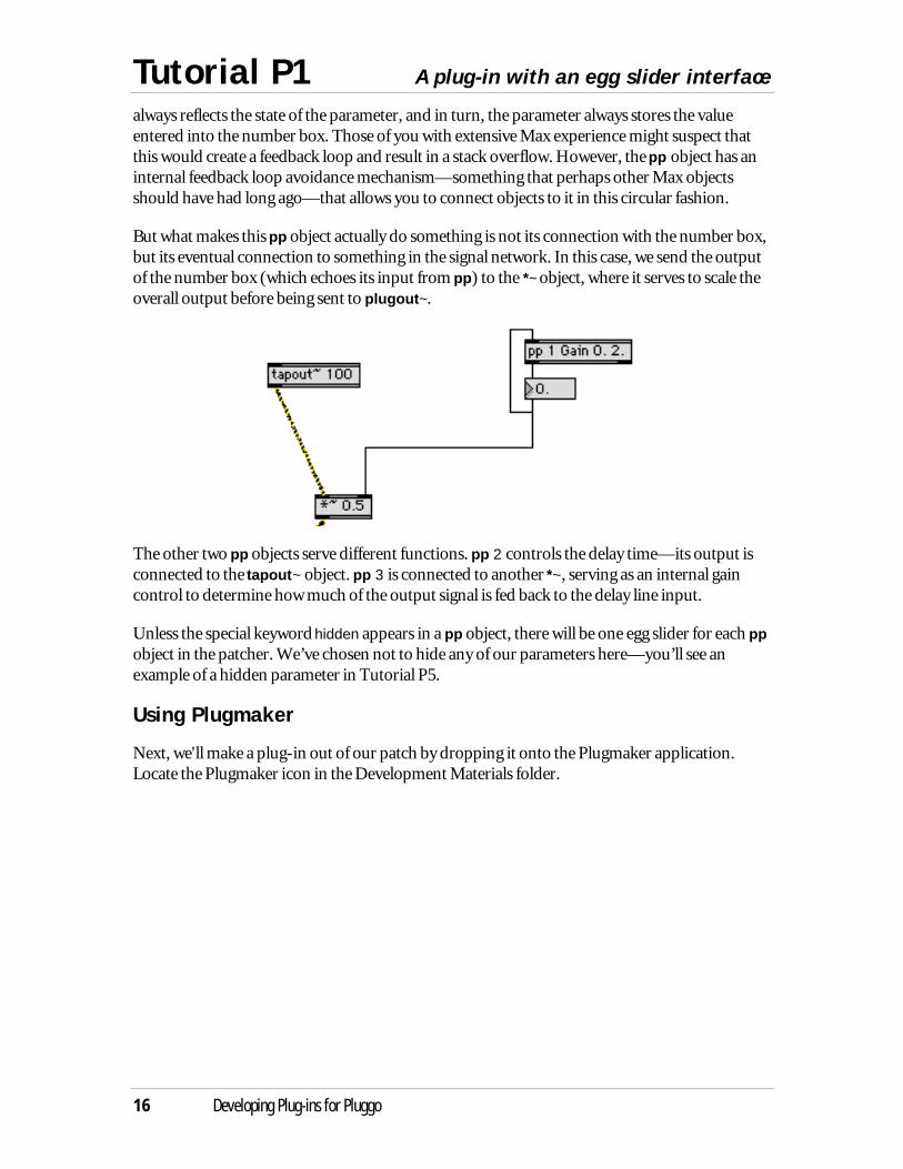
Now look at the part of the tutorial patch labeled Parameter Definition. Here you see several ppobjects. pp is short for plug-in parameter. In developing plug-ins, you’ll be using a lot of theseobjects, so we’ve spared you the inconvenience of having to type in a long object name (pp usedto be called plugparam).
Each pp object defines the parameter number, name, minimum, maximum, and the units to bedisplayed next to the parameter value in the Parameters view of the plug-in edit window. Forinstance, look at the top left pp object shown above, pp 1 Gain 0. 2.. The first argument, 1, saysthis is parameter number 1. The second argument, Gain, says that the parameter’s name is Gain.The third argument, 0., says that the minimum value of the parameter is 0. Note that 0 has adecimal point after it, indicating it’s been entered as a float. This is important, since the type ofthe minimum value sets the type of the parameter values. If the value had been 0 without adecimal point, only integers would be output from the pp object. The fourth argument, 2., setsthe maximum value of the parameter to 2. Knowing how this pp object works, you can probablydetermine the details of the parameters defined by the other pp objects.
Now let’s look at how a pp object is connected to other objects. First, you’ll notice a curiouscircular connection between the float number box and the pp object. This is purely for theconvenience of the plug-in developer for creating effect programs. The user of this plug-in willnever see the number boxes. By connecting the two objects together in this way, the number box
Tutorial P1 A plug-in with an egg slider interface
16 Developing Plug-ins for Pluggo
always reflects the state of the parameter, and in turn, the parameter always stores the valueentered into the number box. Those of you with extensive Max experience might suspect thatthis would create a feedback loop and result in a stack overflow. However, the pp object has aninternal feedback loop avoidance mechanism—something that perhaps other Max objectsshould have had long ago—that allows you to connect objects to it in this circular fashion.
But what makes this pp object actually do something is not its connection with the number box,but its eventual connection to something in the signal network. In this case, we send the outputof the number box (which echoes its input from pp) to the *~ object, where it serves to scale theoverall output before being sent to plugout~.
The other two pp objects serve different functions. pp 2 controls the delay time—its output isconnected to the tapout~ object. pp 3 is connected to another *~, serving as an internal gaincontrol to determine how much of the output signal is fed back to the delay line input.
Unless the special keyword hidden appears in a pp object, there will be one egg slider for each ppobject in the patcher. We’ve chosen not to hide any of our parameters here—you’ll see anexample of a hidden parameter in Tutorial P5.
Using Plugmaker
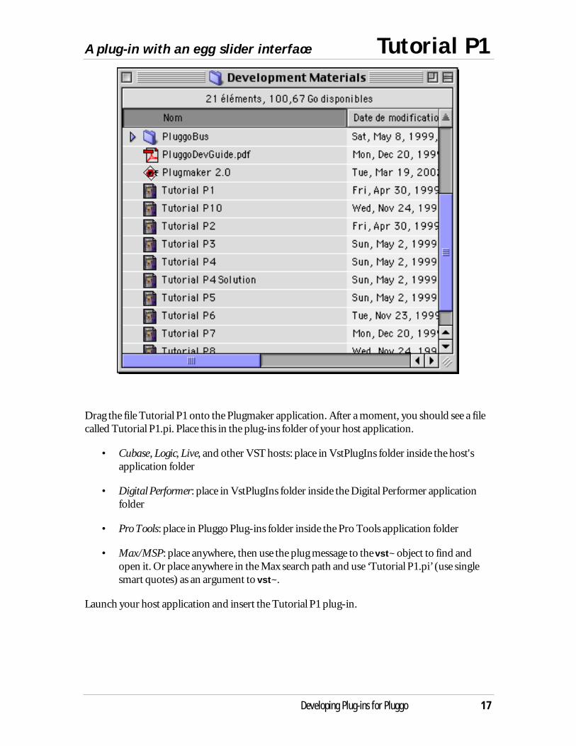
Next, we'll make a plug-in out of our patch by dropping it onto the Plugmaker application.Locate the Plugmaker icon in the Development Materials folder.
A plug-in with an egg slider interface Tutorial P1
Developing Plug-ins for Pluggo 17
Drag the file Tutorial P1 onto the Plugmaker application. After a moment, you should see a filecalled Tutorial P1.pi. Place this in the plug-ins folder of your host application.
• Cubase, Logic, Live, and other VST hosts: place in VstPlugIns folder inside the host'sapplication folder
• Digital Performer: place in VstPlugIns folder inside the Digital Performer applicationfolder
• Pro Tools: place in Pluggo Plug-ins folder inside the Pro Tools application folder
• Max/MSP: place anywhere, then use the plug message to the vst~ object to find andopen it. Or place anywhere in the Max search path and use ‘Tutorial P1.pi’ (use singlesmart quotes) as an argument to vst~.
Launch your host application and insert the Tutorial P1 plug-in.

Tutorial P1 A plug-in with an egg slider interface
18 Developing Plug-ins for Pluggo
You’ll see the following screen:
Test out the plug-in to verify that it does in fact work as a delay.
Then launch Max (if it’s not already running) so you can examine the next tutorial.
Enhancing the plug-in interface Tutorial P2
Developing Plug-ins for Pluggo 19
Improving the User Experience
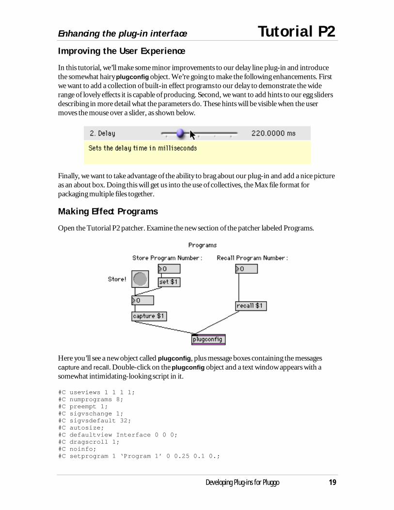
In this tutorial, we’ll make some minor improvements to our delay line plug-in and introducethe somewhat hairy plugconfig object. We’re going to make the following enhancements. Firstwe want to add a collection of built-in effect programs to our delay to demonstrate the widerange of lovely effects it is capable of producing. Second, we want to add hints to our egg slidersdescribing in more detail what the parameters do. These hints will be visible when the usermoves the mouse over a slider, as shown below.
Finally, we want to take advantage of the ability to brag about our plug-in and add a nice pictureas an about box. Doing this will get us into the use of collectives, the Max file format forpackaging multiple files together.
Making Effect Programs
Open the Tutorial P2 patcher. Examine the new section of the patcher labeled Programs.
Here you’ll see a new object called plugconfig, plus message boxes containing the messagescapture and recall. Double-click on the plugconfig object and a text window appears with asomewhat intimidating-looking script in it.
#C useviews 1 1 1 1;#C numprograms 8;#C preempt 1;#C sigvschange 1;#C sigvsdefault 32;#C autosize;#C defaultview Interface 0 0 0;#C dragscroll 1;#C noinfo;#C setprogram 1 ‘Program 1’ 0 0.25 0.1 0.;
Tutorial P2 Enhancing the plug-in interface
20 Developing Plug-ins for Pluggo
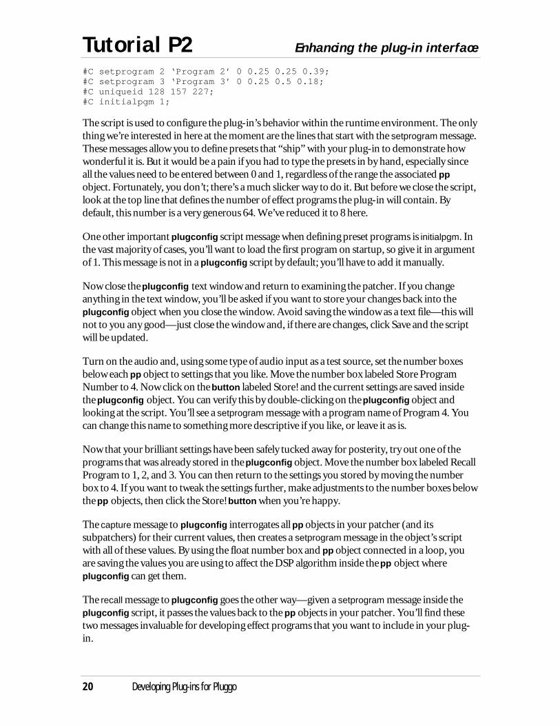
#C setprogram 2 ‘Program 2’ 0 0.25 0.25 0.39;#C setprogram 3 ‘Program 3’ 0 0.25 0.5 0.18;#C uniqueid 128 157 227;#C initialpgm 1;
The script is used to configure the plug-in’s behavior within the runtime environment. The onlything we’re interested in here at the moment are the lines that start with the setprogram message.These messages allow you to define presets that “ship” with your plug-in to demonstrate howwonderful it is. But it would be a pain if you had to type the presets in by hand, especially sinceall the values need to be entered between 0 and 1, regardless of the range the associated ppobject. Fortunately, you don’t; there’s a much slicker way to do it. But before we close the script,look at the top line that defines the number of effect programs the plug-in will contain. Bydefault, this number is a very generous 64. We’ve reduced it to 8 here.
One other important plugconfig script message when defining preset programs is initialpgm. Inthe vast majority of cases, you’ll want to load the first program on startup, so give it in argumentof 1. This message is not in a plugconfig script by default; you’ll have to add it manually.
Now close the plugconfig text window and return to examining the patcher. If you changeanything in the text window, you’ll be asked if you want to store your changes back into theplugconfig object when you close the window. Avoid saving the window as a text file—this willnot to you any good—just close the window and, if there are changes, click Save and the scriptwill be updated.
Turn on the audio and, using some type of audio input as a test source, set the number boxesbelow each pp object to settings that you like. Move the number box labeled Store ProgramNumber to 4. Now click on the button labeled Store! and the current settings are saved insidethe plugconfig object. You can verify this by double-clicking on the plugconfig object andlooking at the script. You’ll see a setprogram message with a program name of Program 4. Youcan change this name to something more descriptive if you like, or leave it as is.
Now that your brilliant settings have been safely tucked away for posterity, try out one of theprograms that was already stored in the plugconfig object. Move the number box labeled RecallProgram to 1, 2, and 3. You can then return to the settings you stored by moving the numberbox to 4. If you want to tweak the settings further, make adjustments to the number boxes belowthe pp objects, then click the Store! button when you’re happy.
The capture message to plugconfig interrogates all pp objects in your patcher (and itssubpatchers) for their current values, then creates a setprogram message in the object’s scriptwith all of these values. By using the float number box and pp object connected in a loop, youare saving the values you are using to affect the DSP algorithm inside the pp object whereplugconfig can get them.
The recall message to plugconfig goes the other way—given a setprogram message inside theplugconfig script, it passes the values back to the pp objects in your patcher. You’ll find thesetwo messages invaluable for developing effect programs that you want to include in your plug-in.
Enhancing the plug-in interface Tutorial P2
Developing Plug-ins for Pluggo 21
Adding Descriptive Information to Parameters
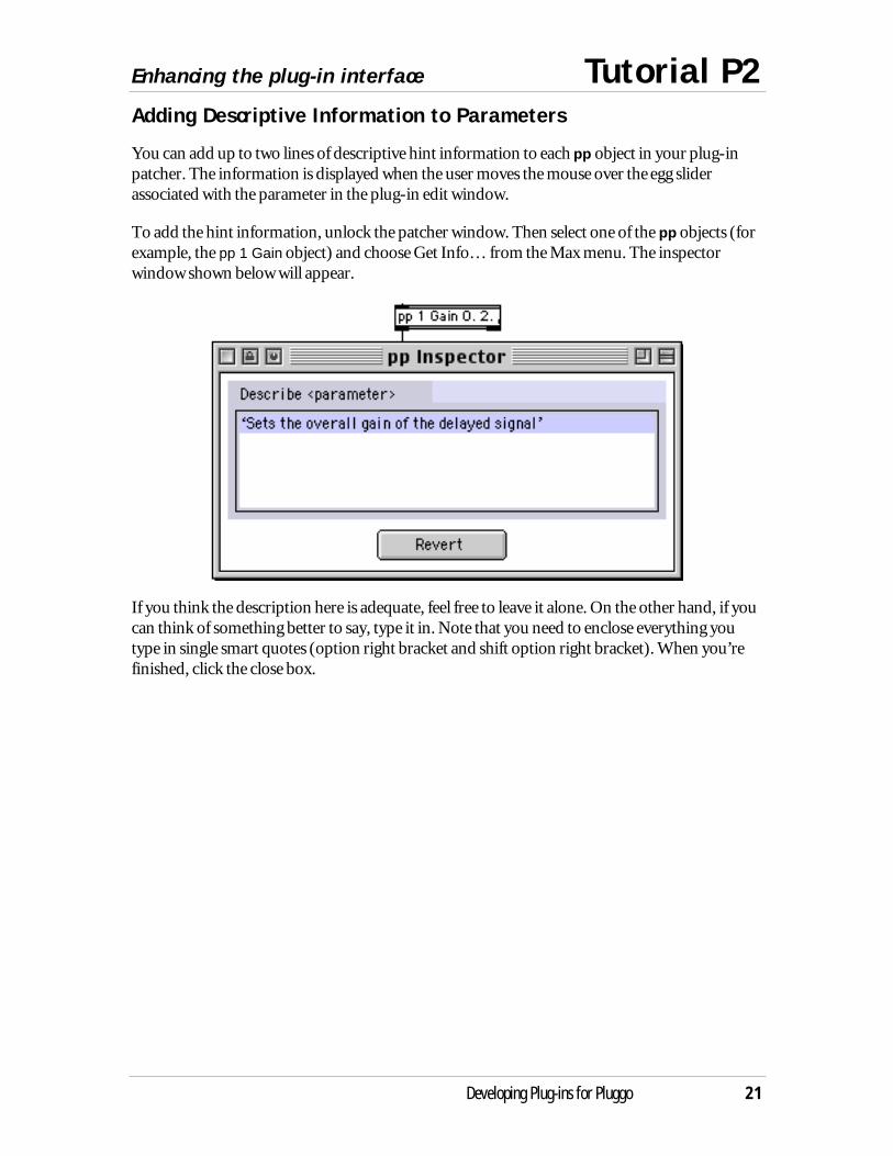
You can add up to two lines of descriptive hint information to each pp object in your plug-inpatcher. The information is displayed when the user moves the mouse over the egg sliderassociated with the parameter in the plug-in edit window.
To add the hint information, unlock the patcher window. Then select one of the pp objects (forexample, the pp 1 Gain object) and choose Get Info… from the Max menu. The inspectorwindow shown below will appear.
If you think the description here is adequate, feel free to leave it alone. On the other hand, if youcan think of something better to say, type it in. Note that you need to enclose everything youtype in single smart quotes (option right bracket and shift option right bracket). When you’refinished, click the close box.
Tutorial P2 Enhancing the plug-in interface
22 Developing Plug-ins for Pluggo
Adding a Plug-in About Box
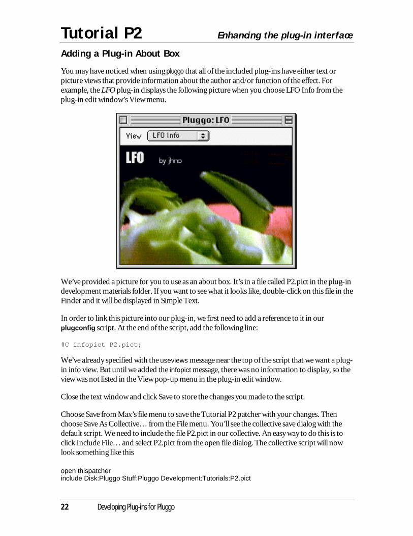
You may have noticed when using pluggo that all of the included plug-ins have either text orpicture views that provide information about the author and/or function of the effect. Forexample, the LFO plug-in displays the following picture when you choose LFO Info from theplug-in edit window’s View menu.
We’ve provided a picture for you to use as an about box. It’s in a file called P2.pict in the plug-indevelopment materials folder. If you want to see what it looks like, double-click on this file in theFinder and it will be displayed in Simple Text.
In order to link this picture into our plug-in, we first need to add a reference to it in ourplugconfig script. At the end of the script, add the following line:
#C infopict P2.pict;
We’ve already specified with the useviews message near the top of the script that we want a plug-in info view. But until we added the infopict message, there was no information to display, so theview was not listed in the View pop-up menu in the plug-in edit window.
Close the text window and click Save to store the changes you made to the script.
Choose Save from Max’s file menu to save the Tutorial P2 patcher with your changes. Thenchoose Save As Collective… from the File menu. You’ll see the collective save dialog with thedefault script. We need to include the file P2.pict in our collective. An easy way to do this is toclick Include File… and select P2.pict from the open file dialog. The collective script will nowlook something like this
open thispatcherinclude Disk:Pluggo Stuff:Pluggo Development:Tutorials:P2.pict
Enhancing the plug-in interface Tutorial P2
Developing Plug-ins for Pluggo 23
(The exact path of the file P2.pict may be different for your computer.)
Click Make and the collective will be created. Call it P2.clct.
Now quit Max. In the Finder, drag the file P2.clct you just created onto the Plugmaker icon.
A new plug-in file will be created called P2.clct.pi in the same directory as P2.clct. You can movethis file into your sequencer’s plug-ins folder and it will be listed in the effect menu the next timethe sequencer launches, or if you are using a VST host, you can just open it where it is with thePluggo plug-in.
Now let’s look at the fruit of our labors. Launch your sequencer and insert the P2.clct plug-in.Open its edit window. First, notice the lovely hints when you move over the egg sliders.
The plug-in file is listed in the sequencer’s menu as P2.clct even though the filename isP2.clct.pi. When displaying a plug-in’s name, sequencers use the name associatedwith the aEff resource, not the filename. The Plugmaker application names the aEffbased on the name of its input file. You can verify this by looking at the aEff resourceinside the file generated by Plugmaker in ResEdit.
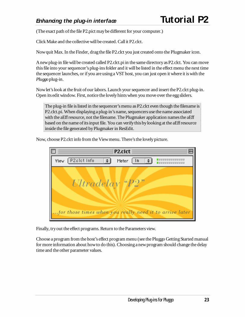
Now, choose P2.clct info from the View menu. There’s the lovely picture.
Finally, try out the effect programs. Return to the Parameters view.
Choose a program from the host’s effect program menu (see the Pluggo Getting Started manualfor more information about how to do this). Choosing a new program should change the delaytime and the other parameter values.

Tutorial P3 A plug-in with a Max interface
24 Developing Plug-ins for Pluggo
In this tutorial, we’ll expand upon the previous examples to examine a patcher that implementsa vibrato effect—also using a delay line—and has a Max patcher as an interface rather thanmaking use of egg sliders. You’ll see that things get quite a bit messier as the Max patch attemptsto serve three functions simultaneously: signal network, parameter definition, and slick userinterface.
The Wonders of Modulated Interpolating Delay Lines
You can do a lot of fun things with a time-varying signal connected to the inlet of a tapout~object. In this example, we’ve connected a cycle~ object to the input of tapout~. The effect ofthe oscillator on the delay line is a pitch-changing effect that sounds pretty much like vibrato.
Another feature of this plug-in is that it is fully stereo, unlike the patchers in the first twotutorials. There are two tapout~ objects, each of which is being modulated by the same cycle~object. In traditional jargon, the cycle~ modulator is functioning as an LFO (low frequencyoscillator).
A *~ scales the output of the cycle~ oscillator so it is appropriate for controlling delay time. Inaddition, a sig~ object is used to offset the oscillator with a fixed delay time. If the base delaytime were 0, the delay time input to tapout~ would go negative—and since tapout~ would clip it
A plug-in with a Max interface Tutorial P3
Developing Plug-ins for Pluggo 25
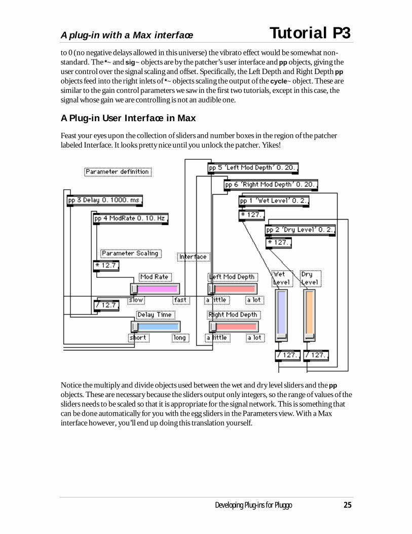
to 0 (no negative delays allowed in this universe) the vibrato effect would be somewhat non-standard. The *~ and sig~ objects are by the patcher’s user interface and pp objects, giving theuser control over the signal scaling and offset. Specifically, the Left Depth and Right Depth ppobjects feed into the right inlets of *~ objects scaling the output of the cycle~ object. These aresimilar to the gain control parameters we saw in the first two tutorials, except in this case, thesignal whose gain we are controlling is not an audible one.
A Plug-in User Interface in Max
Feast your eyes upon the collection of sliders and number boxes in the region of the patcherlabeled Interface. It looks pretty nice until you unlock the patcher. Yikes!
Notice the multiply and divide objects used between the wet and dry level sliders and the ppobjects. These are necessary because the sliders output only integers, so the range of values of thesliders needs to be scaled so that it is appropriate for the signal network. This is something thatcan be done automatically for you with the egg sliders in the Parameters view. With a Maxinterface however, you’ll end up doing this translation yourself.
Tutorial P3 A plug-in with a Max interface
26 Developing Plug-ins for Pluggo
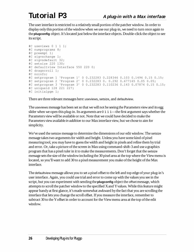
The user interface is restricted to a relatively small portion of the patcher window. In order todisplay only this portion of the window when we use our plug-in, we need to turn once again tothe plugconfig object. It’s located just below the interface objects. Double-click the object to seeits script.
#C useviews 0 1 1 1;#C numprograms 8;#C preempt 1;#C sigvschange 1;#C sigvsdefault 32;#C setsize 220 130;#C defaultview Interface 550 220 0;#C dragscroll 1;#C noinfo;#C setprogram 1 ‘Program 1’ 0 0.232283 0.228346 0.103 0.1496 0.15 0.15;#C setprogram 2 ‘Program 2’ 0 0.232283 0. 0.292 0.677165 0.05 0.05;#C setprogram 3 ‘Program 3’ 0 0.232283 0.110236 0.143 0.07874 0.15 0.15;#C uniqueid 128 221 227;#C initialpgm 1;
There are three relevant messages here: useviews, setsize, and defaultview.
The useviews message has been set so that we will not be seeing the Parameters view and its eggslider when we open this plug-in. Its arguments are 0 1 1 1—the first argument says whether theParameters view will be available or not. Note that we could have decided to make theParameters view available in addition to our Max interface view, but we chose to aim forsimplicity.
We’ve used the setsize message to determine the dimensions of our edit window. The setsizemessage takes two arguments for width and height. Unless you have some kind of pixelmeasuring tool, you may have to guess the width and height in pixels and refine them by trialand error. Or, take a picture of the screen in Max using command-shift-3 and use a graphicsprogram that has a pixel ruler in it to make the measurements. Don’t forget that the setsizemessage sets the size of the window including the 30 pixel area at the top where the View menu islocated, so you’ll want to add 30 to a pixel measurement you make of the height of the Maxinterface.
The defaultview message allows you to set a pixel offset to the left and top edge of your plug-in’suser interface. Again, you could use trial and error to come up with the values you see in thescript, but you can experiment with sending the plugconfig object the offset message, whichattempts to scroll the patcher window to the specified X and Y values. While this feature mightappear handy at first glance, it’s made somewhat awkward by the fact that you are scrolling theinterface that lets you change the scroll offset. If you measure the interface, remember tosubtract 30 to the Y offset in order to account for the View menu area at the top of the editwindow.
A plug-in with a Max interface Tutorial P3
Developing Plug-ins for Pluggo 27
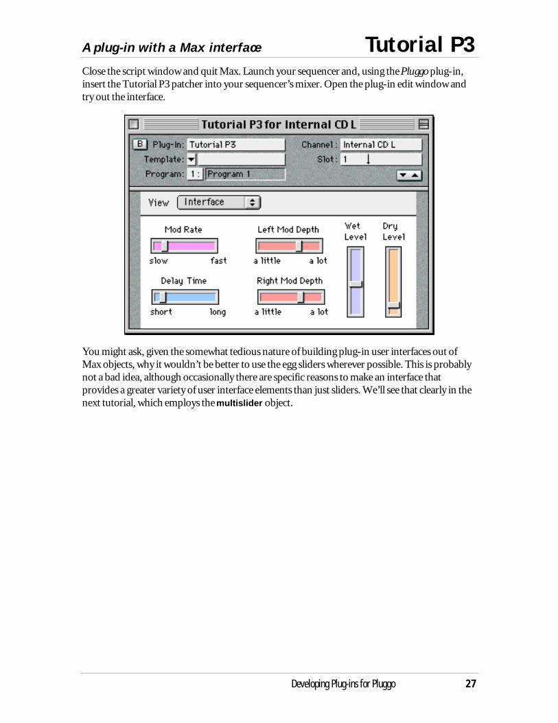
Close the script window and quit Max. Launch your sequencer and, using the Pluggo plug-in,insert the Tutorial P3 patcher into your sequencer’s mixer. Open the plug-in edit window andtry out the interface.
You might ask, given the somewhat tedious nature of building plug-in user interfaces out ofMax objects, why it wouldn’t be better to use the egg sliders wherever possible. This is probablynot a bad idea, although occasionally there are specific reasons to make an interface thatprovides a greater variety of user interface elements than just sliders. We’ll see that clearly in thenext tutorial, which employs the multislider object.

Tutorial P4 Using multislider and plugmultiparam
28 Developing Plug-ins for Pluggo
Collections of Parameters
In this tutorial, we continue with our modulated delay line, but this time, we replace our simpleoscillator with a function that steps through a sequence of delay times. A ramp between the delaytimes in the sequence creates a pitch shift effect. The patcher is similar in its structure to theCyclotron and Flange-o-tron effects included with Pluggo, which apply repeating sequences tofilter and flanger parameters.
The multislider object turns out to be an ideal object for setting a large number of similarparameters, and there’s a plug-in parameter definition object that works with it calledplugmultiparam. Yes, the name is a mouthful compared to pp, but plugmultiparam does thework of a lot of pp objects, so you’ll probably not have to type its name very often.
Here’s how multislider and plugmultiparam are typically connected to each other.
The plugmultiparam object defines a collection of up to 256 parameters. The first argument setsthe index of the first parameter in the collection. The next argument sets the size of thecollection. Here we’ve set our size to 4, corresponding to four steps in the repeating sequence.
Even though the plugmultiparam object defines a collection of parameters, it’s possible thatonly one parameter within the collection will change at a time. As an example, consider the casewhere a single parameter in the collection is being automated within the host environment.plugmultiparam tries to avoid sending a giant list message with its entire collection ofparameters whenever a single value changes. Instead, it uses the little-known select message tothe multislider object that allows a single slider value to be changed. The select message alsocauses multislider to output its current set of values as a list.
Let’s examine how the list of values coming from the multislider are communicated to the delayalgorithm. Our goal is to use the line~ object to feed a sort of “envelope” of target-time pairs tothe tapout~ object. But we have only the four “target” values in the multislider, so we need toinsert millisecond values into the list output from the multislider. This requires a fair amount ofwhat some computer types call munging. It’s hard to give a precise definition of the wordmunge, but it has something to do with taking a collection of data, messing with its innards, andtrying to put it back together without destroying its integrity.
Using multislider and plugmultiparam Tutorial P4
Developing Plug-ins for Pluggo 29
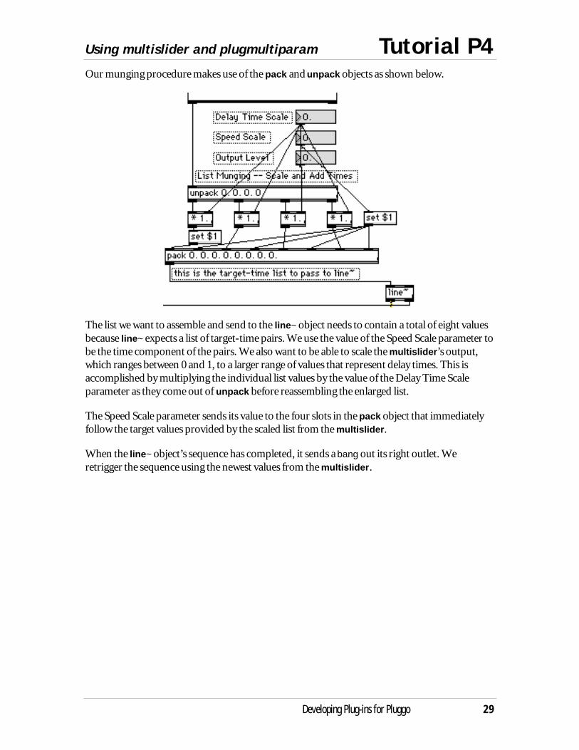
Our munging procedure makes use of the pack and unpack objects as shown below.
The list we want to assemble and send to the line~ object needs to contain a total of eight valuesbecause line~ expects a list of target-time pairs. We use the value of the Speed Scale parameter tobe the time component of the pairs. We also want to be able to scale the multislider’s output,which ranges between 0 and 1, to a larger range of values that represent delay times. This isaccomplished by multiplying the individual list values by the value of the Delay Time Scaleparameter as they come out of unpack before reassembling the enlarged list.
The Speed Scale parameter sends its value to the four slots in the pack object that immediatelyfollow the target values provided by the scaled list from the multislider.
When the line~ object’s sequence has completed, it sends a bang out its right outlet. Weretrigger the sequence using the newest values from the multislider.
Tutorial P4 Using multislider and plugmultiparam
30 Developing Plug-ins for Pluggo
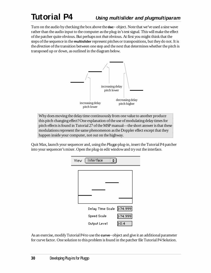
Turn on the audio by checking the box above the dac~ object. Note that we’ve used a sine waverather than the audio input to the computer as the plug-in’s test signal. This will make the effectof the patcher quite obvious. But perhaps not that obvious. At first you might think that thesteps of the sequence in the multislider represent pitches or transpositions, but they do not. It isthe direction of the transition between one step and the next that determines whether the pitch istransposed up or down, as outlined in the diagram below.
increasing delaypitch lower
increasing delaypitch lower
decreasing delaypitch higher
Why does moving the delay time continuously from one value to another producethis pitch changing effect? One explanation of the use of modulating delay times forpitch effects is found in Tutorial 27 of the MSP manual—the short answer is that thesemodulations represent the same phenomenon as the Doppler effect except that theyhappen inside your computer, not out on the highway.
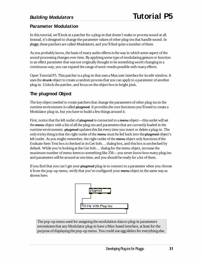
Quit Max, launch your sequencer and, using the Pluggo plug-in, insert the Tutorial P4 patcherinto your sequencer’s mixer. Open the plug-in edit window and try out the interface.
As an exercise, modify Tutorial P4 to use the curve~ object and give it an additional parameterfor curve factor. One solution to this problem is found in the patcher file Tutorial P4 Solution.
Building Modulators Tutorial P5
Developing Plug-ins for Pluggo 31
Parameter Modulation
In this tutorial, we’ll look at a patcher for a plug-in that doesn’t make or process sound at all.Instead, it’s designed to change the parameter values of other plug-ins that handle sound. Inpluggo, these patchers are called Modulators, and you’ll find quite a number of them.
As you probably know, the basis of many audio effects is the way in which some aspect of thesound processing changes over time. By applying some type of modulating gesture or functionto an effect parameter that was not originally thought to be something worth changing in acontinuous way, you can expand the range of sonic results possible with many effects.
Open Tutorial P5. This patcher is a plug-in that uses a Max user interface for its edit window. Ituses the drunk object to create a random process that you can apply to a parameter of anotherplug-in. Unlock the patcher, and focus on the object box in bright pink.
The plugmod Object
The key object needed to create patchers that change the parameters of other plug-ins in theruntime environment is called plugmod. It provides the core functions you’ll need to create aModulator plug-in, but you have to build a few things around it.
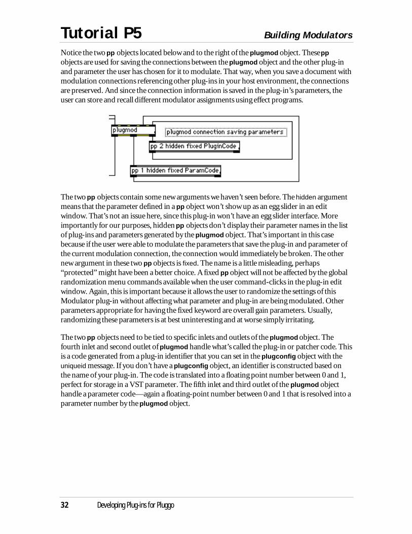
First, notice that the left outlet of plugmod is connected to a menu object—this outlet will setthe menu object with a list of all the plug-ins and parameters that are currently loaded in theruntime environment. plugmod updates this list every time you insert or delete a plug-in. Theonly tricky thing is that the right outlet of the menu must be fed back into the plugmod object’sleft outlet. As you might remember, the right outlet of the menu object only functions if theEvaluate Item Text box is checked in its Get Info… dialog box, and this box is unchecked bydefault. While you’re looking at the Get Info… dialog for the menu object, increase themaximum number of menu items to something like 256—you never know how many plug-insand parameters will be around at one time, and you should be ready for a lot of them.
If you find that you can’t get your plugmod plug-in to connect to a parameter when you chooseit from the pop-up menu, verify that you’ve configured your menu object in the same way asshown here.
The pop-up menu used for assigning the modulation data to plug-in parametersnecessitates that any Modulator plug-in have a Max-based interface, at least for thepurpose of displaying the pop-up menu. You could use egg sliders for everything else.
Tutorial P5 Building Modulators
32 Developing Plug-ins for Pluggo
Notice the two pp objects located below and to the right of the plugmod object. These ppobjects are used for saving the connections between the plugmod object and the other plug-inand parameter the user has chosen for it to modulate. That way, when you save a document withmodulation connections referencing other plug-ins in your host environment, the connectionsare preserved. And since the connection information is saved in the plug-in’s parameters, theuser can store and recall different modulator assignments using effect programs.
The two pp objects contain some new arguments we haven’t seen before. The hidden argumentmeans that the parameter defined in a pp object won’t show up as an egg slider in an editwindow. That’s not an issue here, since this plug-in won’t have an egg slider interface. Moreimportantly for our purposes, hidden pp objects don’t display their parameter names in the listof plug-ins and parameters generated by the plugmod object. That’s important in this casebecause if the user were able to modulate the parameters that save the plug-in and parameter ofthe current modulation connection, the connection would immediately be broken. The othernew argument in these two pp objects is fixed. The name is a little misleading, perhaps“protected” might have been a better choice. A fixed pp object will not be affected by the globalrandomization menu commands available when the user command-clicks in the plug-in editwindow. Again, this is important because it allows the user to randomize the settings of thisModulator plug-in without affecting what parameter and plug-in are being modulated. Otherparameters appropriate for having the fixed keyword are overall gain parameters. Usually,randomizing these parameters is at best uninteresting and at worse simply irritating.
The two pp objects need to be tied to specific inlets and outlets of the plugmod object. Thefourth inlet and second outlet of plugmod handle what’s called the plug-in or patcher code. Thisis a code generated from a plug-in identifier that you can set in the plugconfig object with theuniqueid message. If you don’t have a plugconfig object, an identifier is constructed based onthe name of your plug-in. The code is translated into a floating point number between 0 and 1,perfect for storage in a VST parameter. The fifth inlet and third outlet of the plugmod objecthandle a parameter code—again a floating-point number between 0 and 1 that is resolved into aparameter number by the plugmod object.

Building Modulators Tutorial P5
Developing Plug-ins for Pluggo 33
Generating Modulation Information
Now that we’ve managed to get through the required overhead associated with the plugmodobject, lets examine how we actually do crazy things to the parameters of some unsuspectingplug-in.
In addition to the two parameters used for saving the modulation connection, the Tutorial P5patcher contains three additional parameters that configure the random process used togenerate modulation data. The Interval pp object just sets the interval of a metro object that issending a bang to the drunk object. The Step Size pp object controls the size of the jumps thedrunk object is allowed to make. A larger Step Size will produce more discontinuities in thedrunk output. Finally, the Minimum and Range parameters let the user adjust the range overwhich the drunk object output produces values.
The plugmod object has three inlets that can be used for modulation data. In this tutorial, we’reonly concerned with the left inlet, where incoming data simply sets the value of the parameter.The second inlet takes incoming number and offsets the current value of the modulatedparameter, and the third inlet scales the current value of the modulated parameter by theincoming number.
It’s important to note that regardless of the actual range of a parameter being modulated, thenumber sent to the left inlet of plugmod must be within the 0 to 1 range. 1 will represent themaximum value of the parameter, and 0 will represent the minimum value of the parameter. Asan example, suppose we choose to modulate an LFO Speed parameter that ranges from 3 Hz to20 Hz. Sending a 0 into the left inlet of plugmod will set the LFO Speed parameter to 3. Sendinga value of 0.5 into the left inlet of plugmod will set the parameter to the middle of its range, or11.5. And sending a value of 1.0 into the left inlet of plugmod will set the parameter to itsmaximum value of 20.
Tutorial P5 Building Modulators
34 Developing Plug-ins for Pluggo
The output of drunk, which is an integer between 0 and 127, is scaled so that it falls between 0and 1. The Minimum and Range parameters provide further scaling along with an offset toconstrain the final output range of the random process to a subset of the 0 to 1 range. We use aslider to give some indication to the user what the process is doing.
Unfortunately, it’s not possible to test a plugmod connection within Max. You’ll need to loadthe patcher into the runtime environment along with another plug-in created with Max/MSP.Or, you can also use the Pluggo plug-in to open any VST plug-in. Once hosted by Pluggo, theVST plug-in’s parameters become available in the pop-up menu generated by plugmod.
In order to test this patcher, quit Max and launch your sequencer, inserting the Pluggo plug-inand choosing Tutorial P5 from the open file dialog.
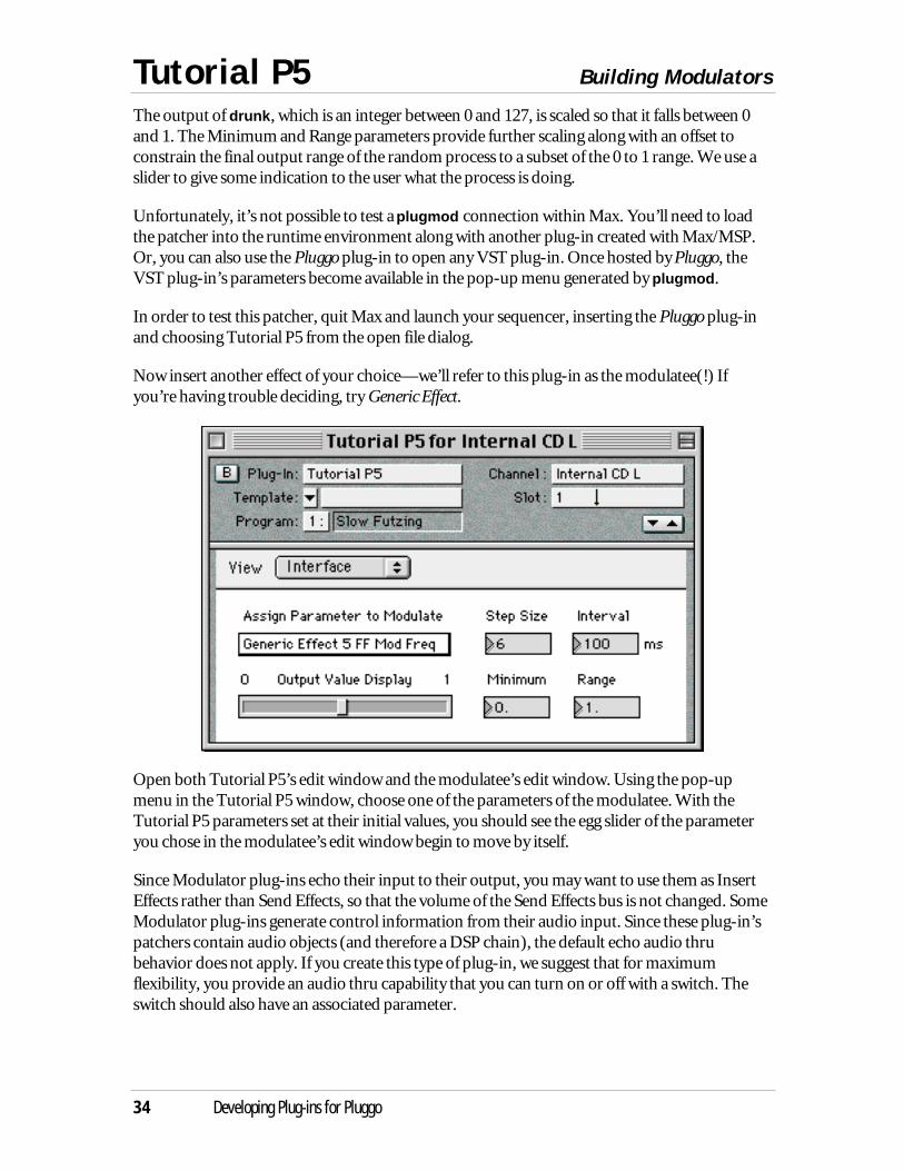
Now insert another effect of your choice—we’ll refer to this plug-in as the modulatee(!) Ifyou’re having trouble deciding, try Generic Effect.
Open both Tutorial P5’s edit window and the modulatee’s edit window. Using the pop-upmenu in the Tutorial P5 window, choose one of the parameters of the modulatee. With theTutorial P5 parameters set at their initial values, you should see the egg slider of the parameteryou chose in the modulatee’s edit window begin to move by itself.
Since Modulator plug-ins echo their input to their output, you may want to use them as InsertEffects rather than Send Effects, so that the volume of the Send Effects bus is not changed. SomeModulator plug-ins generate control information from their audio input. Since these plug-in’spatchers contain audio objects (and therefore a DSP chain), the default echo audio thrubehavior does not apply. If you create this type of plug-in, we suggest that for maximumflexibility, you provide an audio thru capability that you can turn on or off with a switch. Theswitch should also have an associated parameter.
Host synchronization with plugsync~ Tutorial P6
Developing Plug-ins for Pluggo 35
Utilizing Host Syncronization Information
In this tutorial, we’ll look at using an object called plugsync~ that can report synchronizationinformation from the host application. Synchronization information will always include thecount of samples processed by the host, but it may also include bar, beat, tempo, and transportinformation. We’ll use the synchronization information to control how we sample a waveformthat is used to modulate a parameter of another plug-in.
Open Tutorial P6 in Max/MSP. Because Max/MSP does not currently provide bar, beat, andtempo information to plug-ins, this tutorial is best demonstrated within another hostapplication. However, before doing this, it is worth examining the patch within Max to see howit works.
Using plugsync~
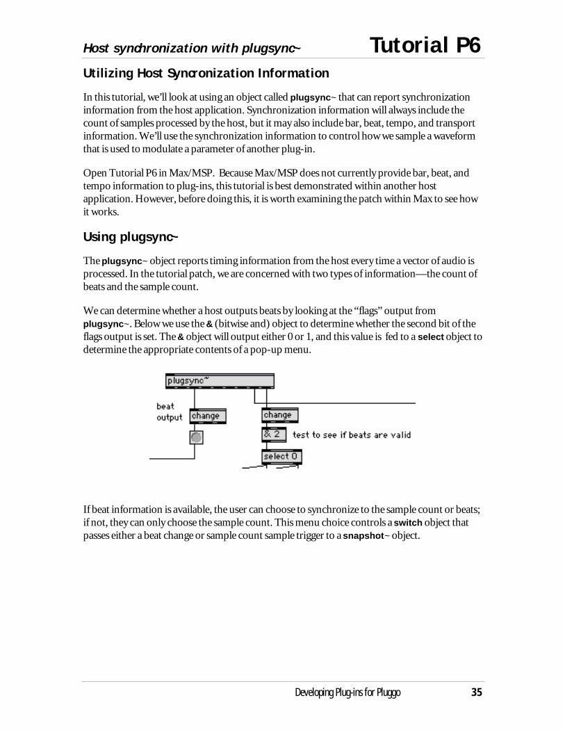
The plugsync~ object reports timing information from the host every time a vector of audio isprocessed. In the tutorial patch, we are concerned with two types of information—the count ofbeats and the sample count.
We can determine whether a host outputs beats by looking at the “flags” output fromplugsync~. Below we use the & (bitwise and) object to determine whether the second bit of theflags output is set. The & object will output either 0 or 1, and this value is fed to a select object todetermine the appropriate contents of a pop-up menu.
If beat information is available, the user can choose to synchronize to the sample count or beats;if not, they can only choose the sample count. This menu choice controls a switch object thatpasses either a beat change or sample count sample trigger to a snapshot~ object.
Tutorial P6 Host synchronization with plugsync~
36 Developing Plug-ins for Pluggo
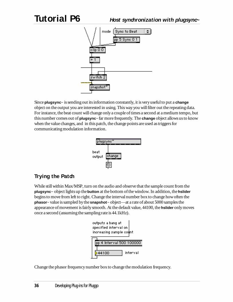
Since plugsync~ is sending out its information constantly, it is very useful to put a changeobject on the output you are interested in using. This way you will filter out the repeating data.For instance, the beat count will change only a couple of times a second at a medium tempo, butthis number comes out of plugsync~ far more frequently. The change object allows us to knowwhen the value changes, and in this patch, the change points are used as triggers forcommunicating modulation information.
Trying the Patch
While still within Max/MSP, turn on the audio and observe that the sample count from theplugsync~ object lights up the button at the bottom of the window. In addition, the hsliderbegins to move from left to right. Change the interval number box to change how often thephasor~ value is sampled by the snapshot~ object—at a rate of about 5000 samples theappearance of movement is fairly smooth. At the default value, 44100, the hslider only movesonce a second (assuming the sampling rate is 44.1kHz).
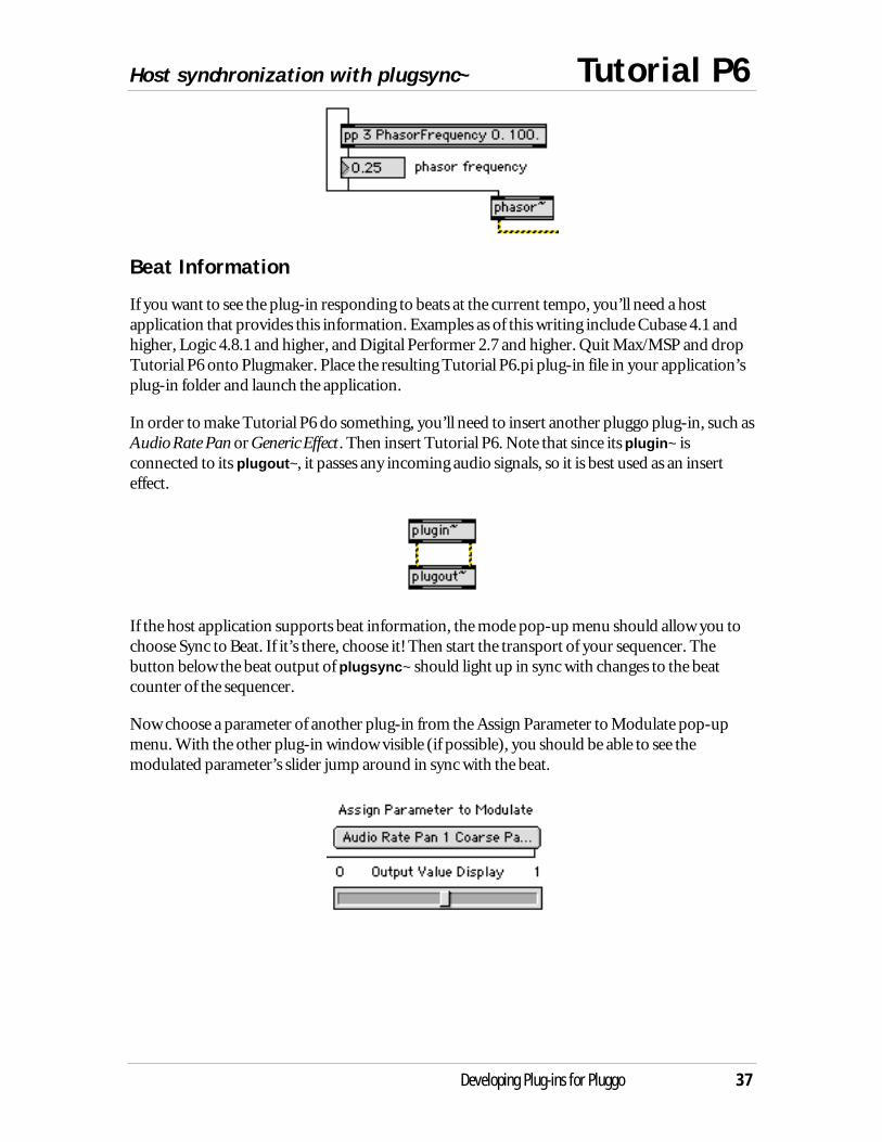
Change the phasor frequency number box to change the modulation frequency.
Host synchronization with plugsync~ Tutorial P6
Developing Plug-ins for Pluggo 37
Beat Information
If you want to see the plug-in responding to beats at the current tempo, you’ll need a hostapplication that provides this information. Examples as of this writing include Cubase 4.1 andhigher, Logic 4.8.1 and higher, and Digital Performer 2.7 and higher. Quit Max/MSP and dropTutorial P6 onto Plugmaker. Place the resulting Tutorial P6.pi plug-in file in your application’splug-in folder and launch the application.
In order to make Tutorial P6 do something, you’ll need to insert another pluggo plug-in, such asAudio Rate Pan or Generic Effect. Then insert Tutorial P6. Note that since its plugin~ isconnected to its plugout~, it passes any incoming audio signals, so it is best used as an inserteffect.
If the host application supports beat information, the mode pop-up menu should allow you tochoose Sync to Beat. If it’s there, choose it! Then start the transport of your sequencer. Thebutton below the beat output of plugsync~ should light up in sync with changes to the beatcounter of the sequencer.
Now choose a parameter of another plug-in from the Assign Parameter to Modulate pop-upmenu. With the other plug-in window visible (if possible), you should be able to see themodulated parameter’s slider jump around in sync with the beat.
Tutorial P7 Audio-rate synchronization
38 Developing Plug-ins for Pluggo
Audio Rate Pan
In this tutorial, we look at synchronization at audio rate. The Audio Rate Pan plug-in, part of thepluggo collection, is provided here in patcher form for you to examine. You’ll be able to see howto perform audio-rate synchronization with the host application using the plugphasor~ object.Audio Rate Pan is fairly complicated, especially in how the pptempo and pptime objects areused. We aren’t going to cover these objects in-depth in this tutorial; instead we’ll briefly explainthe way plugphasor~ is used.
Using plugphasor~ and rate~
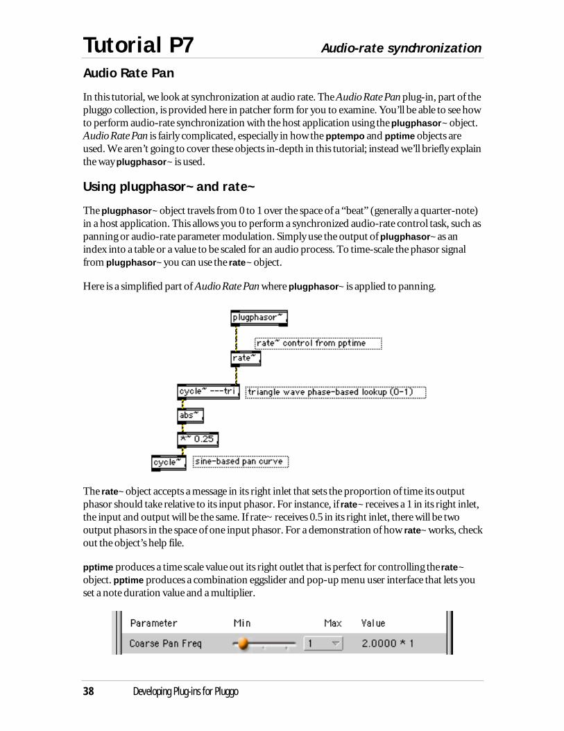
The plugphasor~ object travels from 0 to 1 over the space of a “beat” (generally a quarter-note)in a host application. This allows you to perform a synchronized audio-rate control task, such aspanning or audio-rate parameter modulation. Simply use the output of plugphasor~ as anindex into a table or a value to be scaled for an audio process. To time-scale the phasor signalfrom plugphasor~ you can use the rate~ object.
Here is a simplified part of Audio Rate Pan where plugphasor~ is applied to panning.
The rate~ object accepts a message in its right inlet that sets the proportion of time its outputphasor should take relative to its input phasor. For instance, if rate~ receives a 1 in its right inlet,the input and output will be the same. If rate~ receives 0.5 in its right inlet, there will be twooutput phasors in the space of one input phasor. For a demonstration of how rate~ works, checkout the object’s help file.
pptime produces a time scale value out its right outlet that is perfect for controlling the rate~object. pptime produces a combination eggslider and pop-up menu user interface that lets youset a note duration value and a multiplier.
Audio-rate synchronization Tutorial P7
Developing Plug-ins for Pluggo 39
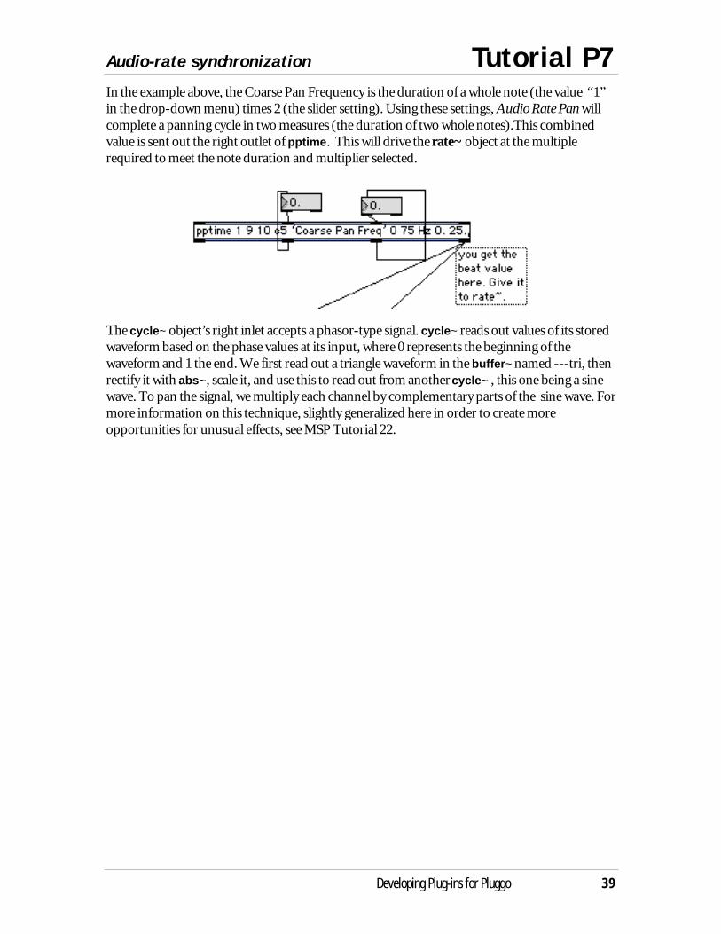
In the example above, the Coarse Pan Frequency is the duration of a whole note (the value “1”in the drop-down menu) times 2 (the slider setting). Using these settings, Audio Rate Pan willcomplete a panning cycle in two measures (the duration of two whole notes).This combinedvalue is sent out the right outlet of pptime. This will drive the rate~ object at the multiplerequired to meet the note duration and multiplier selected.
The cycle~ object’s right inlet accepts a phasor-type signal. cycle~ reads out values of its storedwaveform based on the phase values at its input, where 0 represents the beginning of thewaveform and 1 the end. We first read out a triangle waveform in the buffer~ named ---tri, thenrectify it with abs~, scale it, and use this to read out from another cycle~ , this one being a sinewave. To pan the signal, we multiply each channel by complementary parts of the sine wave. Formore information on this technique, slightly generalized here in order to create moreopportunities for unusual effects, see MSP Tutorial 22.
Tutorial P8 MIDI input
40 Developing Plug-ins for Pluggo
A Really Simple Synthesizer
In this tutorial, we look making a plug-in respond to MIDI input using the plugmidiin object.The example is an ugly-sounding monophonic synthesizer with a very basic interface, but thetechnique for implementing MIDI is the important thing to illustrate here.
Open Tutorial P8 in Max/MSP. At the top of the patch, we’ve provided three options for MIDIcontrol of the synthesis in the patch. If you want to test the patch in Max, you can send MIDI toyour computer and it should come out of the midiin object. If you want to generate fake MIDIevents yourself, you can use the number and message boxes provided. But when inserted as aplug-in, the MIDI will come from the plugmidiin object.
Interpreting MIDI
In all three types of input, the MIDI is in the form of raw bytes of the MIDI specification. Forour simplified case, we’re only interested in note-on and note-off messages. For moreinformation about the format of MIDI messages, see the MIDI topic in the Max Tutorials andTopics manual. Generally, three numbers (which come out in order from midiin or plugmidiin)form a note message. The first identifies the message as a note message and specifies a channelnumber from 1-16. The second number is the note number (for example, 60 is middle C). Thethird number is the key velocity. If the third number is 0, it is a note-off message and thesynthesizer should turn off the note it is playing at the specified pitch.
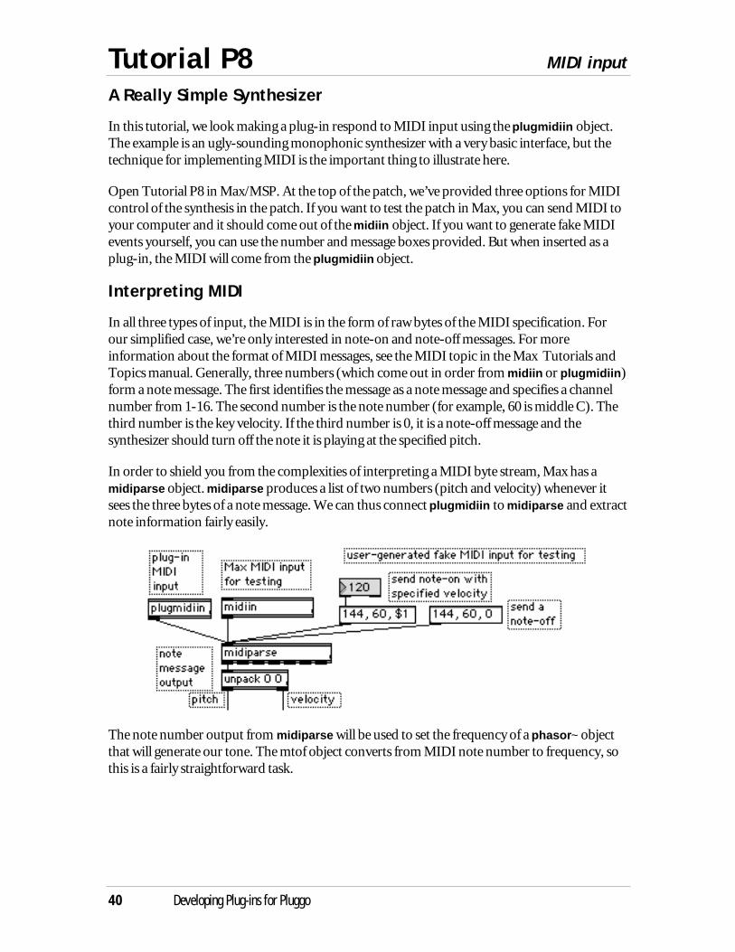
In order to shield you from the complexities of interpreting a MIDI byte stream, Max has amidiparse object. midiparse produces a list of two numbers (pitch and velocity) whenever itsees the three bytes of a note message. We can thus connect plugmidiin to midiparse and extractnote information fairly easily.
The note number output from midiparse will be used to set the frequency of a phasor~ objectthat will generate our tone. The mtof object converts from MIDI note number to frequency, sothis is a fairly straightforward task.

MIDI input Tutorial P8
Developing Plug-ins for Pluggo 41
Attack-Decay-Release Envelope
With the velocity value, we want to control an amplitude envelope. We have a simple envelopeimplementation using the line~ object. Three parameters of the plug-in control the attack,decay, and release times. The attack time is the time from the onset of the note until the soundreaches its full amplitude as calculated from the specific velocity value from the MIDI note-onmessage. The decay is the time between the full amplitude value and the point at which theamplitude is half its full value. The note will stay at this value for as long it is “held down” (inother words, until the MIDI note-off is received). Then the release determines the time theamplitude takes to reach zero after the note-off.
attack time decay time
note-on
release time
note-off
To calculate the amplitude based on the MIDI velocity value, we use a linedrive object to scalethe incoming velocity values according to an exponential curve. For more information on theworkings of the mysterious linedrive object, see the MSP manual. A better implementationwould scale the times exponentially too; this envelope gives a fairly small range of time values.
Tutorial P8 MIDI input
42 Developing Plug-ins for Pluggo
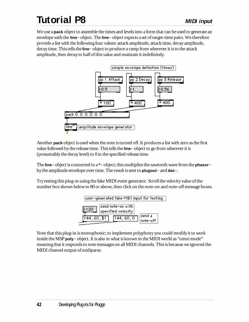
We use a pack object to assemble the times and levels into a form that can be used to generate anenvelope with the line~ object. The line~ object expects a set of target-time pairs. We thereforeprovide a list with the following four values: attack amplitude, attack time, decay amplitude,decay time. This tells the line~ object to produce a ramp from wherever it is to the attackamplitude, then decay to half of this value and maintain it indefinitely.
Another pack object is used when the note is turned off. It produces a list with zero as the firstvalue followed by the release time. This tells the line~ object to go from wherever it is(presumably the decay level) to 0 in the specified release time.
The line~ object is connected to a *~ object; this multiplies the sawtooth wave from the phasor~by the amplitude envelope over time. The result is sent to plugout~ and dac~.
Try testing this plug-in using the fake MIDI event generator. Scroll the velocity value of thenumber box shown below to 80 or above, then click on the note-on and note-off message boxes.
Note that this plug-in is monophonic; to implement polyphony you could modify it to workinside the MSP poly~ object. It is also in what is known in the MIDI world as “omni mode”meaning that it responds to note messages on all MIDI channels. This is because we ignored theMIDI channel output of midiparse.
MIDI input Tutorial P8
Developing Plug-ins for Pluggo 43
plugconfig synth
In order for this plug-in to receive MIDI input in many host applications, it needs to advertiseitself as a synthesizer. To do this, you use the synth keyword in your plugconfig script. Open thescript by double-clicking on the plugconfig object to see this.
#C synth;
Trying the Synth as a Plug-in
Now let’s insert this patch as an instrument plug-in and send it MIDI. Make a plug-in out ofTutorial P8 by dropping it onto Plugmaker. Then deposit into the plug-ins folder of the hostapplication. Host applications that allow you to send MIDI to plug-ins include Cubase, Logic,Digital Performer, Max/MSP, and Pro Tools. Please refer to the Pluggo Getting Started manualfor information on how to insert instrument plug-ins. We do provide quick instructions belowfor getting Tutorial P8 to work in Cubase.
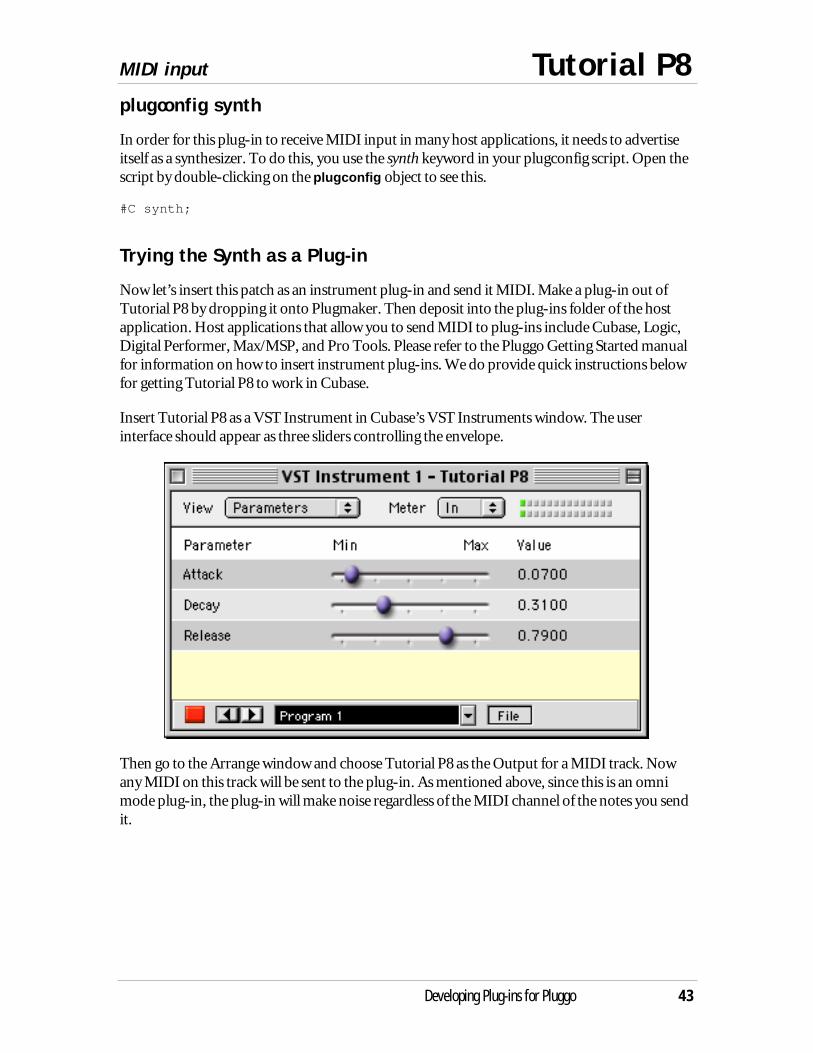
Insert Tutorial P8 as a VST Instrument in Cubase’s VST Instruments window. The userinterface should appear as three sliders controlling the envelope.
Then go to the Arrange window and choose Tutorial P8 as the Output for a MIDI track. Nowany MIDI on this track will be sent to the plug-in. As mentioned above, since this is an omnimode plug-in, the plug-in will make noise regardless of the MIDI channel of the notes you sendit.

Tutorial P9 MIDI output and processing
44 Developing Plug-ins for Pluggo
A MIDI processor
Plug-ins can send MIDI events as well as receive them. In this tutorial, we create a MIDIprocessor using the plugmidiin and plugmidiout objects. However, as of this writing, the onlyapplication we’ve found that can properly handle this type of plug-in is Digital Performer 3.0 orlater. You could also use Max/MSP, but that seems a bit silly, since it’s so simple to write MIDIprocessing patches without having to go through the plug-in interface provided by vst~. Theplug-in MIDI implementations of other host applications suffer from what might be seen as abasic design flaw, which is that the MIDI output of audio plug-ins is merged with all otherincoming MIDI. This can create a nasty feedback loop, since as we saw in the last tutorial, theoutput of MIDI tracks is fed to the plug-in. However, there is a fairly easy way to get “MIDIprocessing” to work in Digital Performer 3, so we’ll provide instructions on how to do thisbelow. In addition, we take advantage of the sync information provided in Digital Performer tocreate a MIDI delay effect that is rhythmically useful.
There appears to be no way currently to get MIDI output from a plug-in in Pro Tools.
Let’s proceed to look at the MIDI processing patch. Open Tutorial P9 in Max/MSP.Unfortunately, this patch can only be used effectively in a host environment withsynchronization features, so we’ll only be able to examine it here.
Changing Note Data
The Tutorial P9 patch transforms MIDI notes coming from plugmidiin in three ways. First,notes can be delayed in sync with the host’s beat timing information. Second, the velocity ofnotes can be scaled. And third, notes can be transposed by adding or subtracting from their notenumber. Once the notes have been transformed, they are formatted back into MIDI messagesand sent to the plugmidiout object where they are communicated to the host, which as wediscussed above, could mean a number of different things.
The patch takes incoming note messages from plugmidiin and sends them to a pipe object sothey can be repeated. The same technique using midiparse that we saw in Tutorial P8 is usedhere, but we also store the MIDI channel from the right outlet of midiparse.
MIDI output and processing Tutorial P9
Developing Plug-ins for Pluggo 45
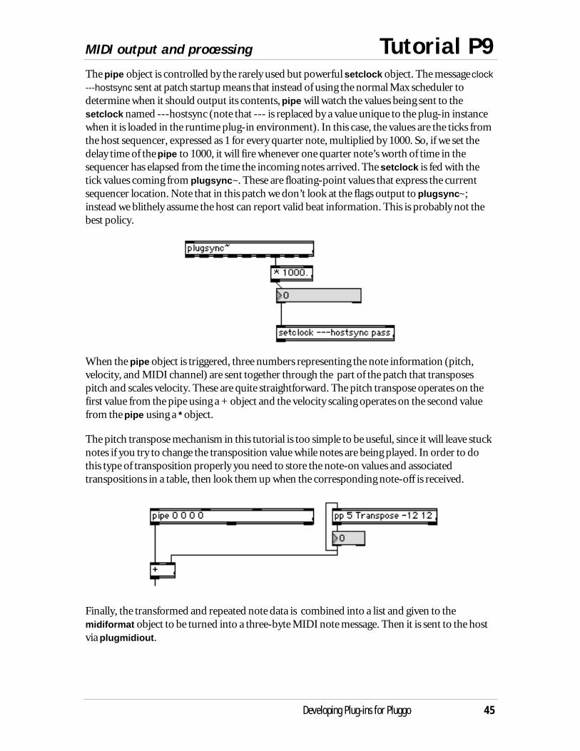
The pipe object is controlled by the rarely used but powerful setclock object. The message clock---hostsync sent at patch startup means that instead of using the normal Max scheduler todetermine when it should output its contents, pipe will watch the values being sent to thesetclock named ---hostsync (note that --- is replaced by a value unique to the plug-in instancewhen it is loaded in the runtime plug-in environment). In this case, the values are the ticks fromthe host sequencer, expressed as 1 for every quarter note, multiplied by 1000. So, if we set thedelay time of the pipe to 1000, it will fire whenever one quarter note’s worth of time in thesequencer has elapsed from the time the incoming notes arrived. The setclock is fed with thetick values coming from plugsync~. These are floating-point values that express the currentsequencer location. Note that in this patch we don’t look at the flags output to plugsync~;instead we blithely assume the host can report valid beat information. This is probably not thebest policy.
When the pipe object is triggered, three numbers representing the note information (pitch,velocity, and MIDI channel) are sent together through the part of the patch that transposespitch and scales velocity. These are quite straightforward. The pitch transpose operates on thefirst value from the pipe using a + object and the velocity scaling operates on the second valuefrom the pipe using a * object.
The pitch transpose mechanism in this tutorial is too simple to be useful, since it will leave stucknotes if you try to change the transposition value while notes are being played. In order to dothis type of transposition properly you need to store the note-on values and associatedtranspositions in a table, then look them up when the corresponding note-off is received.
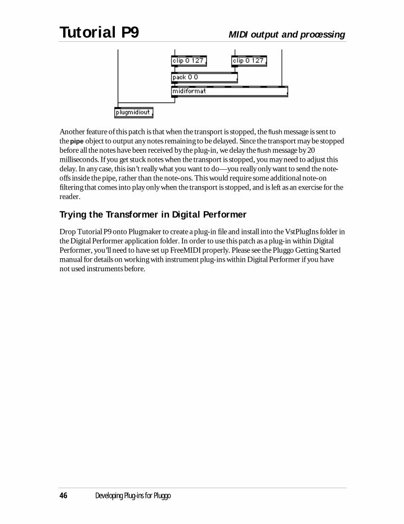
Finally, the transformed and repeated note data is combined into a list and given to themidiformat object to be turned into a three-byte MIDI note message. Then it is sent to the hostvia plugmidiout.
Tutorial P9 MIDI output and processing
46 Developing Plug-ins for Pluggo
Another feature of this patch is that when the transport is stopped, the flush message is sent tothe pipe object to output any notes remaining to be delayed. Since the transport may be stoppedbefore all the notes have been received by the plug-in, we delay the flush message by 20milliseconds. If you get stuck notes when the transport is stopped, you may need to adjust thisdelay. In any case, this isn’t really what you want to do—you really only want to send the note-offs inside the pipe, rather than the note-ons. This would require some additional note-onfiltering that comes into play only when the transport is stopped, and is left as an exercise for thereader.
Trying the Transformer in Digital Performer
Drop Tutorial P9 onto Plugmaker to create a plug-in file and install into the VstPlugIns folder inthe Digital Performer application folder. In order to use this patch as a plug-in within DigitalPerformer, you’ll need to have set up FreeMIDI properly. Please see the Pluggo Getting Startedmanual for details on working with instrument plug-ins within Digital Performer if you havenot used instruments before.
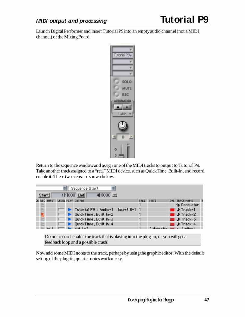
MIDI output and processing Tutorial P9
Developing Plug-ins for Pluggo 47
Launch Digital Performer and insert Tutorial P9 into an empty audio channel (not a MIDIchannel) of the Mixing Board.
Return to the sequence window and assign one of the MIDI tracks to output to Tutorial P9.Take another track assigned to a “real” MIDI device, such as QuickTime, Built-in, and recordenable it. These two steps are shown below.
Do not record-enable the track that is playing into the plug-in, or you will get afeedback loop and a possible crash!
Now add some MIDI notes to the track, perhaps by using the graphic editor. With the defaultsetting of the plug-in, quarter notes work nicely.
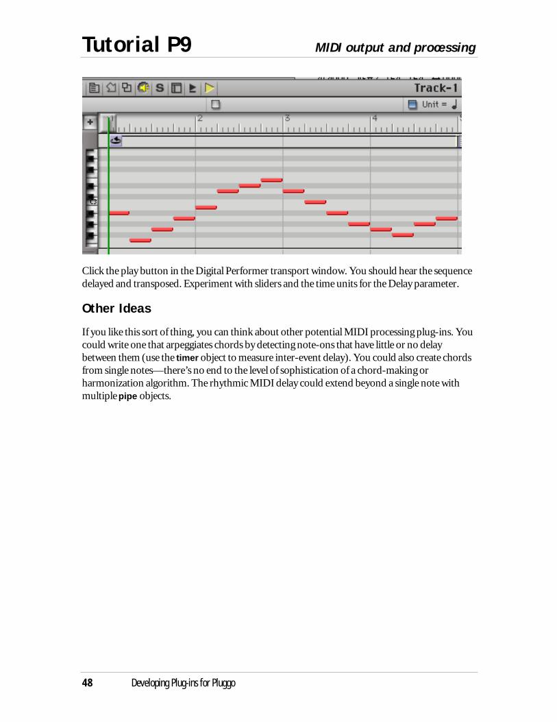
Tutorial P9 MIDI output and processing
48 Developing Plug-ins for Pluggo
Click the play button in the Digital Performer transport window. You should hear the sequencedelayed and transposed. Experiment with sliders and the time units for the Delay parameter.
Other Ideas
If you like this sort of thing, you can think about other potential MIDI processing plug-ins. Youcould write one that arpeggiates chords by detecting note-ons that have little or no delaybetween them (use the timer object to measure inter-event delay). You could also create chordsfrom single notes—there’s no end to the level of sophistication of a chord-making orharmonization algorithm. The rhythmic MIDI delay could extend beyond a single note withmultiple pipe objects.

Using plugmorph Tutorial P10
Developing Plug-ins for Pluggo 49
Morphing
The final tutorial shows off an amusing feature of the plug-in environment where two effectprograms can be averaged to create a new one. The plugmorph object allows you to create newpresets that occupy the “space” between two existing presets. The morphing plug-in in thistutorial is applied to another plug-in’s presets. Since this might not make much sense until youtry it, we’ve reversed the order of this tutorial. First, we want you to try the morphing plug-in,then we’ll explain how it works.
Testing It Out
Drop the Tutorial P10 patch onto Plugmaker. Place the resulting plug-in in your hostapplication’s plug-in folder. Launch the host application and insert the Generic Effect plug-in.Then, on an empty audio channel, insert the Tutorial P10 plug-in.
With the Generic Effect edit window visible, choose Generic Effect from the target plug-in pop-up menu. Then move the slider from Preset 1 to Preset 2. You’ll see the eggsliders in the GenericEffect edit window move from the settings of Preset 1 (Vibrato) to those of Preset 2 (Flange).
How It Works
The plugmorph object is somewhat similar in nature to the plugmod object. Both are designedto work in different plug-ins from the one in which they reside. Like plugmod, the plugmorphobject generates a menu of possible targets, but in this case, the targets are plug-ins, notparameters.
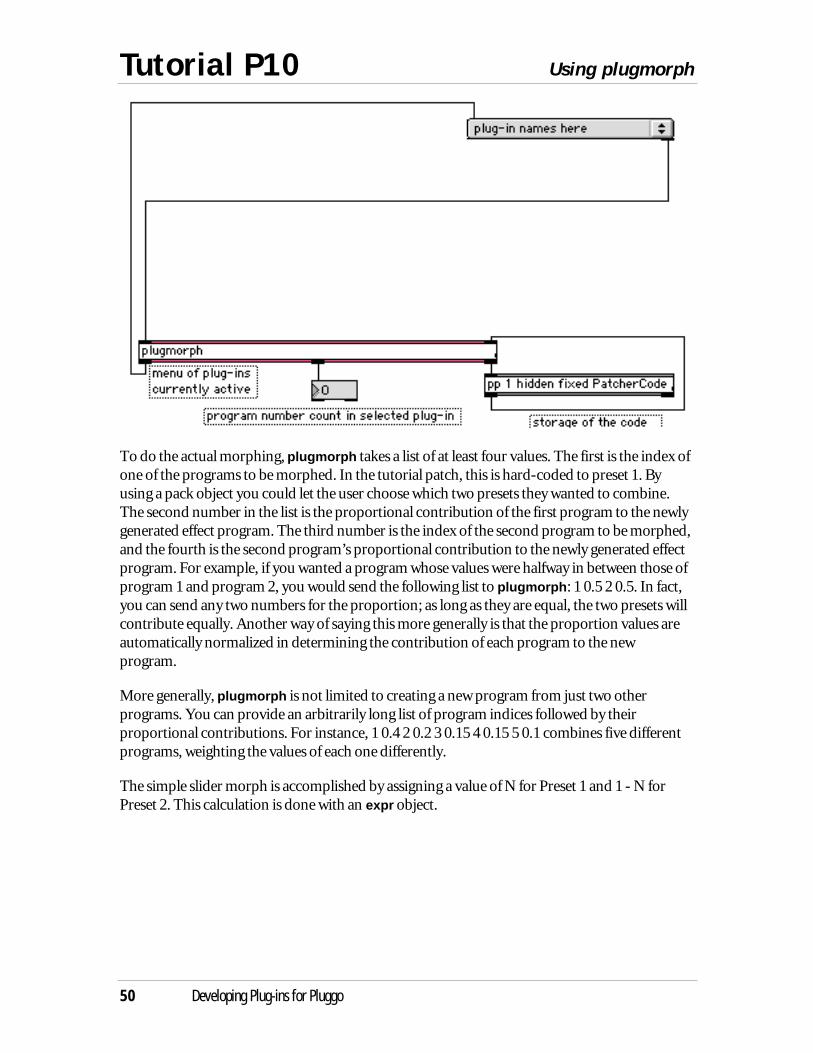
Tutorial P10 Using plugmorph
50 Developing Plug-ins for Pluggo
To do the actual morphing, plugmorph takes a list of at least four values. The first is the index ofone of the programs to be morphed. In the tutorial patch, this is hard-coded to preset 1. Byusing a pack object you could let the user choose which two presets they wanted to combine.The second number in the list is the proportional contribution of the first program to the newlygenerated effect program. The third number is the index of the second program to be morphed,and the fourth is the second program’s proportional contribution to the newly generated effectprogram. For example, if you wanted a program whose values were halfway in between those ofprogram 1 and program 2, you would send the following list to plugmorph: 1 0.5 2 0.5. In fact,you can send any two numbers for the proportion; as long as they are equal, the two presets willcontribute equally. Another way of saying this more generally is that the proportion values areautomatically normalized in determining the contribution of each program to the newprogram.
More generally, plugmorph is not limited to creating a new program from just two otherprograms. You can provide an arbitrarily long list of program indices followed by theirproportional contributions. For instance, 1 0.4 2 0.2 3 0.15 4 0.15 5 0.1 combines five differentprograms, weighting the values of each one differently.
The simple slider morph is accomplished by assigning a value of N for Preset 1 and 1 - N forPreset 2. This calculation is done with an expr object.
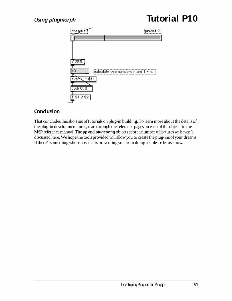
Using plugmorph Tutorial P10
Developing Plug-ins for Pluggo 51
Conclusion
That concludes this short set of tutorials on plug-in building. To learn more about the details ofthe plug-in development tools, read through the reference pages on each of the objects in theMSP reference manual. The pp and plugconfig objects sport a number of features we haven’tdiscussed here. We hope the tools provided will allow you to create the plug-ins of your dreams.If there’s something whose absence is preventing you from doing so, please let us know.

Plugmaker Turn patches and collectives into plug-ins
52 Developing Plug-ins for Pluggo
Introduction
The Plugmaker application transforms a Max patch or collective file into a plug-in file. It createsa new file containing a VST aEff resource from the Pluggo plug-in, along with the patcher orcollective data from the file you dragged. This file can be loaded directly by the sequencer, so theuser will see your GranularLovePotion plug-in in the pop-up menu of available plug-ins ratherthan having to first choose Pluggo and then use a file open dialog box.
Using Plugmaker
To use Plugmaker, just drag the patcher or collective onto Plugmaker’s icon. A new file will becreated in the same folder as the file you dragged with .pi added to the filename. You’ll probablywant to get rid of the .pi extension after you move the file to the VstPlugIns folder of yourfavorite sequencer.
Plug-in Names
The name of your plug-in as displayed in the effect pop-up menu in a typical sequencer is notthe filename of the plug-in (although, oddly enough, the first letter of the filename determinesthe order in which it appears in the menu in some applications). Rather, it is the name given tothe aEff resource. Plugmaker uses the filename of its source—whether patcher or collective—asthe name it gives to this resource.
This means that you should rename your patcher or collective to the name you desire for yourplug-in before dragging it onto Plugmaker.
Parameter Analysis
If Plugmaker can find the necessary libraries and objects in the Max/MSP Runtime Supportfolder inside the Extensions folder, it will load your plug-in in order to analyze its parameters,then store the resulting information in resources inside the plug-in file. Digital Performer andPro Tools need this information in order to load a plug-in, and most VST hosts use plug-insummary information to help them decide where to list the plug-in. For instance, Cubase wantsto know whether a plug-in is a synth or an effect plug-in, so it can list the synths in its menu ofVST Instruments. Plugmaker creates the resources used by most host applications, so they don’tneed to load a plug-in when they find it for the first time.
This analysis happens automatically when Plugmaker is invoked. However, if you find yourplug-in does not appear to be loading within Digital Performer or Pro Tools, try dropping yourplug-in file onto Plugmaker. Occasionally it needs two tries to save this information.
Turn patches and collectives into plug-ins Plugmaker
Developing Plug-ins for Pluggo 53
Plugmaker.nostrip
Plugmaker has the ability to remove selected external objects from the resulting plug-in file,saving disk space for a distribution of, like, 74 plug-ins or something. Create a text file calledPlugmaker.nostrip in the same directory as Plugmaker. In this file, list the Max external objectsyou don’t want removed from the resulting plug-in. Likely candidates for this list would be Maxexternals that you don’t want to distribute by themselves to pluggo users who might also beMax/MSP users, for various reasons including greed and laziness. Of course, including externswithin the plug-in file is a good way to make your plug-in easy to distribute.
If no Plugmaker.nostrip file is found, or if it contains no text, all external objects will be removedfrom the resulting plug-in file.
Plugmaker.vmresources
A feature used internally to create Pluggo can add version information to the plug-ins. Create aresource file called Plugmaker.vmresources in the same folder as the Plugmaker application, andput vers ID=0 and vers ID=1 resources into this file using a resource editor. Set the versresources to contain the desired version information, then drag one or more plug-ins ontoPlugmaker. The vers resources will be added to your plug-ins.
Updating Old Plug-ins
You will need to drop any plug-ins created for previous versions of Pluggo onto Plugmaker 2.0in order for them to work properly in Pluggo 3.
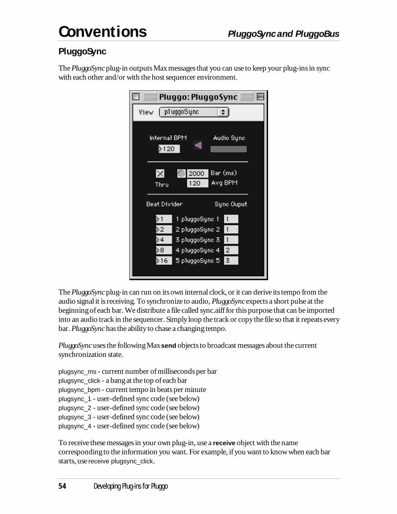
Conventions PluggoSync and PluggoBus
54 Developing Plug-ins for Pluggo
PluggoSync
The PluggoSync plug-in outputs Max messages that you can use to keep your plug-ins in syncwith each other and/or with the host sequencer environment.
The PluggoSync plug-in can run on its own internal clock, or it can derive its tempo from theaudio signal it is receiving. To synchronize to audio, PluggoSync expects a short pulse at thebeginning of each bar. We distribute a file called sync.aiff for this purpose that can be importedinto an audio track in the sequencer. Simply loop the track or copy the file so that it repeats everybar. PluggoSync has the ability to chase a changing tempo.
PluggoSync uses the following Max send objects to broadcast messages about the currentsynchronization state.
plugsync_ms - current number of milliseconds per barplugsync_click - a bang at the top of each barplugsync_bpm - current tempo in beats per minuteplugsync_1 - user-defined sync code (see below)plugsync_2 - user-defined sync code (see below)plugsync_3 - user-defined sync code (see below)plugsync_4 - user-defined sync code (see below)
To receive these messages in your own plug-in, use a receive object with the namecorresponding to the information you want. For example, if you want to know when each barstarts, use receive plugsync_click.
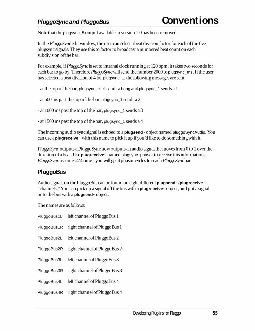
PluggoSync and PluggoBus Conventions
Developing Plug-ins for Pluggo 55
Note that the plugsync_5 output available in version 1.0 has been removed.
In the PluggoSync edit window, the user can select a beat division factor for each of the fiveplugsync signals. They use this to factor to broadcast a numbered beat count on eachsubdivision of the bar.
For example, if PluggoSync is set to internal clock running at 120 bpm, it takes two seconds foreach bar to go by. Therefore PluggoSync will send the number 2000 to plugsync_ms. If the userhas selected a beat division of 4 for plugsync_1, the following messages are sent:
- at the top of the bar, plugsync_click sends a bang and plugsync_1 sends a 1
- at 500 ms past the top of the bar, plugsync_1 sends a 2
- at 1000 ms past the top of the bar, plugsync_1 sends a 3
- at 1500 ms past the top of the bar, plugsync_1 sends a 4
The incoming audio sync signal is echoed to a plugsend~ object named pluggoSyncAudio. Youcan use a plugreceive~ with this name to pick it up if you’d like to do something with it.
PluggoSync outputs a PluggoSync now outputs an audio signal the moves from 0 to 1 over theduration of a beat. Use plugreceive~ named plugsync_phasor to receive this information.PluggoSync assumes 4/4 time - you will get 4 phasor cycles for each PluggoSync bar
PluggoBus
Audio signals on the PluggoBus can be found on eight different plugsend~/plugreceive~“channels.” You can pick up a signal off the bus with a plugreceive~ object, and put a signalonto the bus with a plugsend~ object.
The names are as follows:
PluggoBus1L left channel of PluggoBus 1
PluggoBus1R right channel of PluggoBus 1
PluggoBus2L left channel of PluggoBus 2
PluggoBus2R right channel of PluggoBus 2
PluggoBus3L left channel of PluggoBus 3
PluggoBus3R right channel of PluggoBus 3
PluggoBus4L left channel of PluggoBus 4
PluggoBus4R right channel of PluggoBus 4

Conventions PluggoSync and PluggoBus
56 Developing Plug-ins for Pluggo
The source patchers for both PluggoBus Send and PluggoBus Rcv are included in thedevelopment materials. You can copy these as necessary if you wish to add either selectablePluggoBus send or receive capability into your plug-in.
Runtime Issues
Developing Plug-ins for Pluggo 57
User Interface Limitations
There are some differences between the runtime Max environment as it exists in Max/MSPRuntime and in the plug-in environment. Perhaps the most important one is that the runtimeplug-in environment lets you load a single patcher (with subpatchers), but you can’t view what’sin the subpatchers. Instead, you have a fixed size “view” into a portion of a single patcherwindow. In the VST specification there is no provision for opening anything beyond a singleediting window, so this is a relatively permanent limitation. As a part of this limitation, double-clicking on any Max object within the interface view is disabled. We can’t, however, preventobjects from opening windows in other ways, but it is your responsibility to avoid doing this(and prevent the user from doing this), since most host environments will crash if a foreignwindow enters their space.
Audio Processing
The adc~ and dac~ objects are completely non-functional in the runtime plug-in environment.To get any kind of audio input or output, you will need to use plugin~ and plugout~. Inaddition, the I/O vector size, signal vector size, and sampling rate are determined by the hostenvironment. For older versions of the Sound Manager, many sequencers uses an I/O vectorsize of 1056, which corresponds to some magic value that an FFT-ignorant hardware engineer atApple thought was, in the immortal words of William Casey as reported by Oliver North, “aneat idea.” Luckily, 32, a power of 2, will divide into this number (1056 is 32 x 33), so 32 hasbecome the one and only signal vector size used in the runtime environment. The reason for thisis that it allows all plug-ins to share the same set of signal vectors, which is a gigantic win in termsof CPU utilization since it allows memory that is already in the data cache to be reused. Theprocessor operates much more efficiently when it can access data that is already in the cache.
Note that it is impossible to know the host environment’s “real” audio input or output device.Your patcher, when it works as a plug-in, only has the input and output audio vectors tocommunicate with the outside world.
Initialization
Often people write initialization schemes in their audio patchers that employ delay or pipeobjects triggered from loadbang objects. Usually, this is an attempt to get something to initializein the proper order. The problem is that these schemes will not initialize the patcher before theaudio is turned on. The execution of events connected to loadbang objects is the only thing thathappens in the runtime plug-in environment after a patcher and before the DSP chain iscompiled and executed.
This has specific implications for the cycle~ object when you supply it with a buffer~ objectname as an argument. The cycle~ object copies its wavetable data from the associated buffer~when the DSP chain is compiled. This means that if the contents of the buffer~ have not alreadybeen prepared, the cycle~ object will not have the right data in its wavetable, and nothing shortof sending the cycle~ object a set message will correct the problem. The solution is to initializethe buffer~ entirely from the output of the loadbang without depending on the scheduler, either
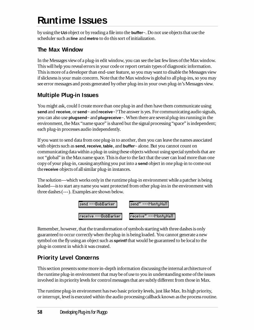
Runtime Issues
58 Developing Plug-ins for Pluggo
by using the Uzi object or by reading a file into the buffer~. Do not use objects that use thescheduler such as line and metro to do this sort of initialization.
The Max Window
In the Messages view of a plug-in edit window, you can see the last few lines of the Max window.This will help you reveal errors in your code or report certain types of diagnostic information.This is more of a developer than end-user feature, so you may want to disable the Messages viewif slickness is your main concern. Note that the Max window is global to all plug-ins, so you maysee error messages and posts generated by other plug-ins in your own plug-in’s Messages view.
Multiple Plug-in Issues
You might ask, could I create more than one plug-in and then have them communicate usingsend and receive, or send~ and receive~? The answer is yes. For communicating audio signals,you can also use plugsend~ and plugreceive~. When there are several plug-ins running in theenvironment, the Max “name space” is shared but the signal processing “space” is independent;each plug-in processes audio independently.
If you want to send data from one plug-in to another, then you can leave the names associatedwith objects such as send, receive, table, and buffer~ alone. But you cannot count oncommunicating data within a plug-in using these objects without using special symbols that arenot “global” in the Max name space. This is due to the fact that the user can load more than onecopy of your plug-in, causing anything you put into a send object in one plug-in to come outthe receive objects of all similar plug-in instances.
The solution—which works only in the runtime plug-in environment while a patcher is beingloaded—is to start any name you want protected from other plug-ins in the environment withthree dashes (---). Examples are shown below.
Remember, however, that the transformation of symbols starting with three dashes is onlyguaranteed to occur correctly when the plug-in is being loaded. You cannot generate a newsymbol on the fly using an object such as sprintf that would be guaranteed to be local to theplug-in context in which it was created.
Priority Level Concerns
This section presents some more in-depth information discussing the internal architecture ofthe runtime plug-in environment that may be of use to you in understanding some of the issuesinvolved in its priority levels for control messages that are subtly different from those in Max.
The runtime plug-in environment has two basic priority levels, just like Max. Its high priority,or interrupt, level is executed within the audio processing callback known as the process routine.
Runtime Issues
Developing Plug-ins for Pluggo 59
The low priority level is generally executed within an idle-time callback. The idle-time callbackhappens when a plug-in window—and this can be any plug-in window owned by the runtimeplug-in environment—is open. There is also a special idle-time callback that is executedwhether or not a plug-in window is open. This is used for loading files into the buffer~ object.
Parameters can be changed by the host as well as by the user of the plug-in. When parameterautomation is employed by the host mixer, parameter changes may be sent from the host to theplug-in at interrupt level. The same holds true if the host automates program changes to theplug-in. Since there is no way in the current VST standard to know the priority level of thecommunication from the host to the plug-in, the runtime plug-in environment has to assumethat all parameter and program change messages from the host occur at interrupt level, since thisis the most restrictive case in terms of how the plug-in must behave. Therefore, it simulates thiscondition by setting a flag during the handling of program and parameter changes sent from thehost declaring that processing is occurring at interrupt level. Objects that behave correctly atinterrupt level in Max should therefore behave correctly in the context of a parameter orprogram change. There might be potential problems with a fake “interrupt level” that itself canbe interrupted, but we haven’t found any so far.
The runtime plug-in environment can tell the difference between parameters as changed by thehost and parameters as changed by the user moving an egg slider or within the plug-in editwindow’s Max-based interface, and it does not simulate the interrupt-level condition in thesetwo situations.
How does any of this information affect your plug-in? Here are some problems that came upduring the development of the PlugLoop and Very Long Delay plug-ins. In both of these plug-ins, there is a parameter that sets the maximum time of a delay line buffer. The output of a ppobject is ultimately connected to a message that causes a sample buffer to be resized. In the caseof both the buffer~ and tapin~ objects, resizing a sample buffer is not something that can bedone “on the fly”—it must be deferred to low priority since on the Macintosh, one cannotallocate memory at interrupt level. When the host sends a program change message (whichresults in all pp objects sending out new parameter values), the runtime plug-in environmentsets a flag telling the Max environment that it is running at interrupt level. This causes the bufferresizing to be deferred until after the program change message. When the host gives the runtimeplug-in environment additional idle time, the resizing actually occurs. In this case at least, youcan see where parameter automation will not occur properly if the plug-in edit window isclosed, since the sample buffer will not be resized until the edit window’s idle time callback isrun. Apparently Waves plug-ins have a similar problem. You should note however that the vastmajority of plug-ins made with Max/MSP will not have a parameter updating problem sincealmost all parameter changes can be handled immediately.
In implementing PlugLoop and Very Long Delay, we did a few things to minimize some of thepotential problems created by the need to defer a time- and memory-consuming operation:
• We used a change object on the output of pp so that the buffers will not be resizedunless the parameter value actually changes
Runtime Issues
60 Developing Plug-ins for Pluggo
• All preset effects programs have the same maximum delay time, so switching among thepresets will not cause buffers to be resized.
• The number box that changes the maximum time in PlugLoop is set to output only onmouse up, so that the buffers won’t resize as the user is deciding how large they shouldbe.
Another problem in PlugLoop was that the clear message was being sent to the buffer~ objectafter a resize. Since PlugLoop uses three buffer~ objects, this was a lot of clearing, and, unlike theresize action, a clear to a buffer~ will be executed immediately. If the program change arrived atinterrupt level, this means the clear would have been executed at interrupt level. It was worse,since there was a delay object before the clear message, causing the message always to be sent(and handled) at interrupt level. The effect of the interrupt-level clearing was to peg the CPUutilization meters of host sequencers. The clear message was unnecessary, since the buffer~ nowclears its memory after resizing, so it was removed. This is the sort of thing you could get awaywith in Max, where no attempt to protect the user from massive CPU overload occurs (onecould argue that a click in the audio output is a lot easier for the user to deal with than a windowpopping up and the sound stopping), but not in a sequencer, where apparently, protecting theuser from hearing any clicks is of prime importance.
Discontinuous DSP Networks
Consider a plug-in that takes input from plugin~ and sends it to record~ to write the data into abuffer. It then reads from the buffer~ using play~ and sends the output to plugout~. The Slice-n-Dice plug-in worked like this, until we discovered it would not work as an insert effect inCubase. As a send effect it was fine. What was happening?
Insert effects in Cubase pass the same signal vectors for their input and output. This means thatyou cannot write a sample to the output vector before reading it from the input vector,otherwise you will write over your input. When you give it a configuration of DSP objects andconnections, the MSP signal compiler—which determines the order of processing in order toexecute your algorithm—is not always that smart. In the Slice-n-Dice case, it had decided it wasOK to perform the play~ to plugout~ section of the algorithm before the plugin~ to record~section. This caused the output vector to be written before the corresponding input vector wasread. This does not cause problems (other than a signal vector size delay) in Max, nor in thesend effect case. But it was a big problem in the Cubase insert effect case since, due to the factthat the buffer~ was initially empty, the play~ to plugout~ code would zero the output (whichwas also the input) before it could be written into the buffer~. The cycle would repeat itself as thezeroed input continued to be written to the buffer~, and no sound would be produced from theplug-in at all.
There are a number of solutions to this problem. The one we adopted was to add a direct signalpath from the input to the output along with a gain control. This was needed to the make theeffect more useful as an insert effect anyway, and it caused the proper sorting of the DSPnetwork by the signal compiler, since there was no longer an ambiguity about which of twodiscontinuous “pieces” of the network should be ordered first.
Runtime Issues
Developing Plug-ins for Pluggo 61
The moral of the story is that if you want to avoid these types of problems you should alwaysinclude a continuous path of signal objects from plugin~ to plugout~ in your plug-in. It doesn’tneed to pass any audio: multiply the signal by 0 if necessary.
Collectives
The Max collective file has a feature that allows you to open more one patcher when thecollective is opened. You do this by including multiple open commands in the collective script.The runtime plug-in environment will only open one patcher when your collective is loaded—the first one it finds. Since it’s not easy to guarantee what patcher is the first one, you shouldavoid using this feature. You can safely include abstractions (separate patcher files that areloaded as subpatchers). These should be added automatically when the collective builderanalyzes the dependencies of your patcher.
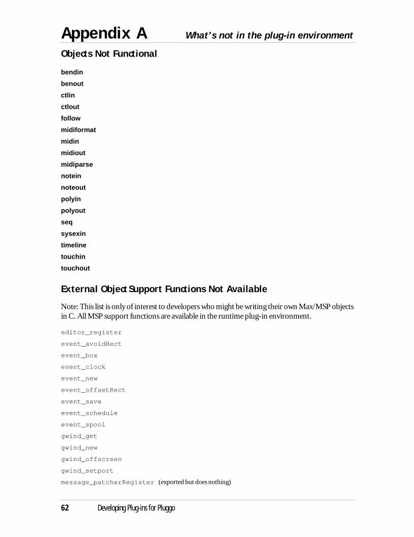
Appendix A What’s not in the plug-in environment
62 Developing Plug-ins for Pluggo
Objects Not Functional
bendin
benout
ctlin
ctlout
follow
midiformat
midin
midiout
midiparse
notein
noteout
polyin
polyout
seq
sysexin
timeline
touchin
touchout
External Object Support Functions Not Available
Note: This list is only of interest to developers who might be writing their own Max/MSP objectsin C. All MSP support functions are available in the runtime plug-in environment.
editor_register
event_avoidRect
event_box
event_clock
event_new
event_offsetRect
event_save
event_schedule
event_spool
gwind_get
gwind_new
gwind_offscreen
gwind_setport
message_patcherRegister (exported but does nothing)
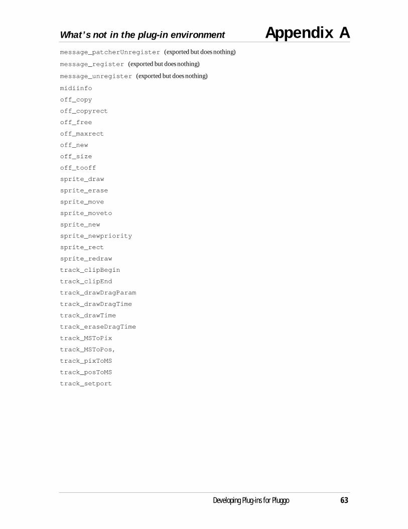
What’s not in the plug-in environment Appendix A
Developing Plug-ins for Pluggo 63
message_patcherUnregister (exported but does nothing)
message_register (exported but does nothing)
message_unregister (exported but does nothing)
midiinfo
off_copy
off_copyrect
off_free
off_maxrect
off_new
off_size
off_tooff
sprite_draw
sprite_erase
sprite_move
sprite_moveto
sprite_new
sprite_newpriority
sprite_rect
sprite_redraw
track_clipBegin
track_clipEnd
track_drawDragParam
track_drawDragTime
track_drawTime
track_eraseDragTime
track_MSToPix
track_MSToPos,
track_pixToMS
track_posToMS
track_setport
Index
64 Developing Plug-ins for Pluggo
about box for plug-in 22adc~ 14, 57assigning modulator connections 32audio input 57beat division 55code resource 12collective script 22collectives 22, 61communicating audio signals 58Cubase 6, 7, 37curve~ 30cycle~ 39, 57dac~ 14, 57default interface 8defaultview 26delay line 14Digital Performer 6, 37, 44Doppler effect 30DSP chain 12, 34effect programs 7, 19egg slider 10, 16, 21, 32, 59envelope 41hints 21host audio program 6host mixer 6host sequencer 6idle-time callback 59info view 22Initialization 57input vectors 12, 57interrupt level 58line~ 29, 41linedrive 41loadbang 57Logic Audio 6, 7, 37Max patcher files 11Max patcher interface 24Max Window 58menu object 31Messages view 58MIDI messages 40MIDI objects 13MIDI processing 44modulating parameters 31modulator plug-ins 31
and audio 34pop-up menu 32
multislider 28, 29select message 28
munging 28name space 58naming plug-ins 52offset 26output vectors 12, 57parameter automation 59parameter code 32parameters 7, 33
defining 15, 28modulating 31morphing 49randomizing 32scaling 25updating 59
Parameters View 10patcher code 32plug-in
naming 52plug-in about box 22
using pictures 22plug-in initialization sequence 57plug-ins
communicating between 58synchronizing 54
plugconfig 7, 19, 26, 43capture 19defaultview 26infopict 22offset 26recall 19script 20setprogram 20setsize 26synth 43uniqueid 32useviews 22, 26
pluggo conventions 54Pluggo plug-in 11PluggoBus 55PluggoSync 54, 55plugin~ 7, 14, 57
Index
Developing Plug-ins for Pluggo 65
Plugmaker 11, 23, 52and Max external objects 53
Plugmaker.nostrip 53plugmidiin 13, 40, 44plugmidiout 13, 45plugmod 31, 32, 33, 34plugmorph 49plugmultiparam 8, 28plugout~ 7, 14, 16, 57plugphasor~ 38plugreceive~ 55, 58plugsend~ 55, 58plugsync~ 35, 45
beat information 35, 37flags 35samplecount 35
pp 8, 15, 20, 28, 32, 59adding hints 21connecting 15fixed 32hidden 32
pptime 38priority levels 58private symbols 58Pro Tools 6process routine 7, 58program 7rate~ 38receive~ 58receive 12, 58runtime plug-in environment 6select 28send 12, 58send~ 58setsize 26sfplay~ 14Sound Manager 57Steinberg 6, 9stereo effects 24subpatchers 57symbols
private 58synchronization 35, 54
audio rate 38synth 40test signals 14
three-dash symbols 58uniqueid 32useviews 22, 26vibrato effect 24View menu 26Vision 8