Embed Size (px)
Citation preview
DEVELOPING BUILDING INFORMATION MODELING (BIM) GUIDELINES FOR
CAMPUS PLANNING AND FACILITIES MANAGEMENT AT
WORCESTER POLYTECHNIC INSTITUTE (WPI)
By
Purvashri Vivek Padhye
A Thesis Submitted to the Faculty of the
WORCESTER POLYTECHNIC INSTITUTE
in partial fulfillment of the requirements for the
Degree of Master of Science in
Construction Project Management
January, 2017
APPROVED:
____________________________________ _______________________________________ Prof. Guillermo Salazar, PhD, Advisor Prof. Leonard Albano, PhD, Committee Member ____________________________________ ______________________________________ Alfredo DiMauro, AIA, Committee Member Prof. Tahar El-Korchi, PhD, Department Head

ii
ABSTRACT
The development of Building Information Modelling (BIM) guidelines for campuses and
universities has evolved on a case-by-case basis and there is no standard format in the
development of these guides. There are however, common elements in these guidelines.
This study reviews the applications of Building Information Modeling (BIM) from the perspective
of owners of higher education campus facilities and proposes a structured approach to develop
documented guidelines to assist the owner’s staff in the use of BIM, primarily with existing
facilities. More specifically, this study proposes a set of guidelines to assist the Facilities
Management department at Worcester Polytechnic Institute (WPI) in using BIM for their existing
campus facilities.
Since 2005, WPI has been using some components of BIM in the design and construction of new
facilities and has extended BIM uses to support facilities and space management in some of the
existing buildings. Some positive experiences and benefits have been derived from these
applications, but to date no formal and systematic approach has been established in
documenting and organizing processes for the different BIM uses on campus.
The objective of this research project is to conduct an extensive review of documented
approaches and guidelines for BIM uses developed by other universities and incorporate the
different experiences with the use of BIM at WPI to create a set of formal guidelines exclusively
for WPI for the efficient implementation of BIM in future design, construction, renovation,
facility, and space management of a facility.

iii
The research collected information from the WPI Facilities Management department through
surveys and interviews, to better understand the current issues associated with facility
management and space planning. A case study analysis that involved the use of 3D Building
Information Models of several buildings on the WPI campus was performed to validate the
possible use of the BIM in the efficient delivery of information for new and renovation projects
as well as for its ability to benefit in the space planning process. Existing documented guidelines
developed by five other universities that have pioneered the development of their guides were
also reviewed to determine common elements in their BIM-based practices and to incorporate
these when applicable into the BIM guide for WPI in such a way that will effectively contribute
to the BIM adoption and standardization of procedures reflecting the unique characteristics of
this institution.
This study identifies the benefits of utilizing BIM and standardization through the BIM guide
primarily for existing construction and facilities management. The attempt to identify
commonalities and standard pieces to develop a BIM guide for WPI will help improve overall
operational efficiency and productivity of the organization. This provides a unique opportunity
to be engaged in the process of standardization, using existing content as a reference to achieve
harmonization of concepts, terms, definitions and the overall structure or framework that the
documented guide is delivered within.
The outcome is a WPI-BIM guide which will help assist facility owners in developing an overall
BIM strategy that supports the organization’s core goals, develops the necessary contract
conditions, and generates implementation plans to successfully execute BIM within the
organization.

iv
ACKNOWLEDGEMENTS
I would like to express my deepest appreciation to all those who encouraged me and helped me
complete this thesis.
A special gratitude to my supervisor, Professor Guillermo Salazar whose guidance, contribution
and encouragement helped me to coordinate and successfully complete this thesis.
I would also like to acknowledge with much appreciation the crucial role of Liz Tomaszewski, for
her stimulating support and suggestions which helped to form the basis for this research.
I want to thank everyone at the Facilities Department for their valuable inputs and time to help
formulate the research, especially Alfredo DiMauro, Jim Bedard, Bill Spratt, Roger Griffin, Theresa
Mailloux and Nick Palumbo.
A big thank you, to Hannah Poirier for coordinating and organizing meetings and presentations
with the Facilities Management department and Cynthia Bergeron for helping with the
administrative procedures within the Civil and Environmental Engineering Department.
I would also like to express my gratitude towards my parents, Leena and Vivek Padhye, and Karan
Barabde for their constant support and encouragement towards the completion of this thesis.

v
TABLE OF CONTENTS
ii. Abstract iii. Acknowledgements v. Table of contents ix. List of figures x. List of tables
1 INTRODUCTION: ......................................................................................................................................... 1
1.1 Background ......................................................................................................................................... 2
1.2 Research Interest ................................................................................................................................ 5
1.3 Need for research ............................................................................................................................... 6
1.4 Research objectives ............................................................................................................................ 7
1.5 Structure of Report ............................................................................................................................. 8
2 LITERATURE REVIEW .................................................................................................................................. 9
2.1 The Facilities Management (FM) process ........................................................................................... 9
2.2 Importance of BIM .............................................................................................................................. 9
2.3 The value of BIM for FM ................................................................................................................... 12
2.4 Advantages of BIM for Facility Management (FM) ........................................................................... 13
2.4.1 Space Management ................................................................................................................... 14
2.4.2 BIM data for Operation, Maintenance, and Retrofits ................................................................ 15
2.4.3 Populating the FM database from a Building Information Model ............................................. 15
2.5 Record and As-built Building Information Model ............................................................................. 18
2.6 BIM Execution Plan (BEP) .................................................................................................................. 19
2.7 Building Information Model – FM Database links............................................................................. 20
2.8 Use of BIM data for maintenance and Retrofits ............................................................................... 21
2.9 Need for a BIM guide ........................................................................................................................ 22
2.10 Objectives of the guide ................................................................................................................... 23
3 METHODOLOGY ....................................................................................................................................... 25
3.1 Conduct a case study on the Facilities Management process .......................................................... 25
3.1.1 Interviews ................................................................................................................................... 27
3.1.2 Research ..................................................................................................................................... 27
3.1.3 Survey ......................................................................................................................................... 27

vi
3.1.4 Proposal ..................................................................................................................................... 28
3.1.5 Priorities ..................................................................................................................................... 28
3.1.6 Design ......................................................................................................................................... 28
3.2 Conduct a case study of existing university BIM guides ................................................................... 28
3.3 Develop a proposal for a BIM guide exclusively for WPI .................................................................. 29
3.4 Validate the contributions of the proposed BIM guide .................................................................... 30
4 WPI FACILITIES MANAGEMENT PROCESS ................................................................................................ 31
4.1 The Facilities Management department ........................................................................................... 31
4.2 BIM uses for FM at WPI: Existing Facilities ....................................................................................... 33
4.2.1 Work done so far ....................................................................................................................... 34
4.2.2 Process of creating BIM for buildings at WPI ............................................................................. 36
4.2.3 Different model parameters ...................................................................................................... 40
4.2.4 Use of the model: ....................................................................................................................... 42
4.2.5 Maintenance of the model ........................................................................................................ 43
4.3 BIM uses for FM at WPI: New facilities ............................................................................................. 43
4.3.1 Case Study 1: WPI Sports and Recreation Center ...................................................................... 44
4.3.1.1 Project Organization ............................................................................................................... 45
4.3.1.2 Architectural and Structural Design ........................................................................................ 46
4.3.1.3 Cost and Schedule ................................................................................................................... 47
4.3.1.4 Facilities Management ............................................................................................................ 47
4.3.2 Case study 2: WPI Foisie Innovation Studio (New ongoing project) .......................................... 49
4.3.2.1 Background ............................................................................................................................. 50
4.3.2.2 Application of BIM .................................................................................................................. 51
4.3.3 Conclusion .................................................................................................................................. 54
5. CASE STUDIES .......................................................................................................................................... 57
5.1 Identify information for Comparative Analysis ................................................................................. 58
5.2 Review guides for common data fields ............................................................................................. 59
5.3 Mapping a common Table of Contents ............................................................................................. 60
5.4 Case studies ...................................................................................................................................... 60
5.4.1 Case 1: Indiana University (IU) ................................................................................................... 60
5.4.1.1 BIM Execution Plan ................................................................................................................. 62
5.4.1.2 IU IPD (Integrated Project Delivery) Methodology Plan ......................................................... 62

vii
5.4.1.3 IU BIM Proficiency Matrix ....................................................................................................... 63
5.4.2 Case 2: Pennsylvania State University ....................................................................................... 64
5.4.3 Case 3: Massachusetts Institute of Technology (MIT) ............................................................... 67
5.4.3.1 Renovations and space change projects requirements .......................................................... 67
5.4.3.2 Capital project requirement ................................................................................................... 68
5.4.4 Case 4: Georgia Tech University ................................................................................................ 69
5.4.4.1 BIM Execution Plan (BEP) ........................................................................................................ 70
5.4.4.2 Integrated Project Methodology Plan (IPP) ............................................................................ 71
5.4.5 Case 5: University of Southern California (USC) ........................................................................ 72
5.4.5.1 BIM Execution plan ................................................................................................................. 73
5.5 Conclusion ......................................................................................................................................... 73
6 WPI-BIM GUILDELINES DOCUMENT STRUCTURE, CONTENTS, AND VALIDATION ................................... 76
6.1 Research findings .............................................................................................................................. 76
6.2 Document Validation ........................................................................................................................ 85
6.2.1 Proof of concept......................................................................................................................... 85
6.2.2 User Feedback ............................................................................................................................ 91
7 CONCLUSION AND FUTURE WORK .......................................................................................................... 93
7.1 Benefits of the BIM Guide ................................................................................................................. 93
7.2 Recommendations ............................................................................................................................ 94
Bibliography .............................................................................................................................................. 100
Appendix A: Terminology .......................................................................................................................... 104
Appendix B: Interview Data ...................................................................................................................... 110
B.1 Questionnaire for Interviews .......................................................................................................... 110
B.2 Interview Feedback ......................................................................................................................... 111
B.2.1 Participant 1: Bill Spratt ........................................................................................................... 111
B.2.2 Participant 2: James Bedard .................................................................................................... 114
B.2.3 Participant 3: Liz Tomaszewski ................................................................................................ 117
B.2.4 Paticipant 4: Nick Palumbo ...................................................................................................... 119
B.2.5 Participant 5: Roger Griffin ...................................................................................................... 121
B.2.6 Participant 6: Theresa Mailloux ............................................................................................... 123
Appendix C: Worcester Polytechnic Institute BIM Guide ......................................................................... 125

viii
LIST OF FIGURES
Figure 1: Cycle of using BIM in Facilities Management ..................................................................................................... 3
Figure 2: BIM Lifecycle Participants ................................................................................................................................. 11
Figure 3: Facilities data links with other systems ............................................................................................................ 14
Figure 4: The Components of a BIM Use ......................................................................................................................... 18
Figure 5: Purposes of BIM Use ......................................................................................................................................... 18
Figure 6: COBie process ................................................................................................................................................... 21
Figure 7: Facilities Department Organization Chart ........................................................................................................ 32
Figure 8: Sample view of Salisbury model ....................................................................................................................... 35
Figure 9: Migrating from CAD to Revit ............................................................................................................................ 36
Figure 10: Sample of the drawing sheet .......................................................................................................................... 39
Figure 11: FICM Space categorization ............................................................................................................................. 42
Figure 12: Completed WPI Sports and Recreation Center Background .......................................................................... 45
Figure 13: External Organization Flowchart .................................................................................................................... 46
Figure 14: Proposed WPI Foisie Innovation Studio .......................................................................................................... 49
Figure 15: Grotesque on Alumni Gym ............................................................................................................................. 51
Figure 16: Map of United States showing case study locations ...................................................................................... 58
Figure 17: Indiana University BIM Guide ......................................................................................................................... 60
Figure 18: Pennsylvania State University BIM Guide ....................................................................................................... 64
Figure 19: Massachusetts Institute of Technology BIM Guide ........................................................................................ 67
Figure 20: Georgia Tech BIM Guide ................................................................................................................................. 69
Figure 21: University of Southern California BIM Guide .................................................................................................. 72
Figure 22: University BIM guides comparison ................................................................................................................. 74
Figure 23: University BIM guides comparison ................................................................................................................. 75
Figure 24: BIM guide project concept.............................................................................................................................. 76
Figure 25: Proposed WPI BIM guide ................................................................................................................................ 77
Figure 26: Drawing sheet indicating plans with detailed dimensions ............................................................................. 86
Figure 27: Drawing sheet indicating Floor Finishes ......................................................................................................... 87
Figure 28: Drawing sheet indicating Ceiling Finishes ...................................................................................................... 87
Figure 29: Drawing sheet indicating Architectural detailing ........................................................................................... 88
Figure 30: Drawing sheet indicating Space Use per FICM codes .................................................................................... 88
Figure 31: Drawing sheet indicating Space Use (door tags) ........................................................................................... 89
Figure 32: Drawing sheet indicating Space Utilization and room capacities. (Room Space Utilization chart enlarged in
Figure 33) ......................................................................................................................................................................... 89
Figure 33: Room Space Utilization chart ......................................................................................................................... 90
Figure 34: Drawing sheet indicating MEP Utilities and locations ................................................................................... 91

ix
LIST OF TABLES
Table 1: BIM guide project concept ................................................................................................................................. 17
Table 2: Comparison of BIM Guides ................................................................................................................................ 64
Table 3: Interview data tabulation .................................................................................................................................. 92
1 INTRODUCTION:
The maintenance and operation of buildings is often the longest and most expensive stage
in the project lifecycle; it accounts for about three times the construction cost (Fuller
2010). The availability of timely and accurate information is an important key element for
the proper operation and maintenance of buildings. This key information is usually
generated during the planning, design, and construction stages of the facility and is
usually delivered in the form of printed or scanned documents when construction is
completed (Goedert & Meadati, 2008). These documents contain the final set of building
plans reflecting the current state of the facility, called as-built drawings; a detailed list of
equipment with serial numbers, model, make, etc.; and warranties and guarantees of the
systems installed in the facility.
Gathering, organizing, and entering this information into the Facilities’ Computer
Maintenance Management System (CMMS) for a typical building can be labor intensive
and, to some extent, an error-prone process with no additional value for the management
of the facility (Gallaher et al, 2004). Building Information Modeling (BIM) is a technology
based collaborative approach that enables different stakeholder and parties involved
through the different phases of the life-cycle of a facility to generate, manage and share
information through a 3D digital model. BIM is used to develop high performing, well-
coordinated designs that deliver desired project outcomes. It is used in new construction,
substantial renovation, major maintenance and improvement, extension projects with a
wide range of alternatives or significant financial impacts.

2
1.1 Background
Building Information Modeling (BIM) as defined in the National BIM standard-United
States “is a digital representation of physical and functional characteristics of a facility. As
such, it serves as a shared knowledge resource for information about a facility, forming a
reliable basis for decisions during its life cycle from inception onward” (National BIM
standard 2015)
A Building Information Model has great benefits for developing and maintaining lifecycle
data for different facilities. It contains data that can be accessed and exported for various
uses during the lifetime of the building for facilities management and operations.
However, the owner does not necessarily benefit from the digital model developed during
design and construction in the future operation and maintenance of the facility. Due to
lack of standardization on how these digital models and information exchanges are
conducted, design and construction integration of BIM doesn’t necessarily result into an
integrated, lifecycle management process.
A well-planned BIM-based lifecycle management process can be developed and
documented as a set of guidelines that, together with the appropriate selection of
software tools, can guide architects and contractors to deliver an information-enriched
data model that is beneficial to the client. When it comes to owners of several large
facilities such as universities, a provision of detailed guidelines and deliverable
requirements for the use and reference of their facilities management building teams,
can assist them in a smooth and successful campus management. For construction
projects undertaken, in which BIM is used, it is important to put together a BIM Execution

3
Plan (BEP) to review and implement all aspects of the process during the various phases
of the project. A BIM Execution Plan is a comprehensive document that helps the project
team identify and derive the benefits of BIM for a project through the different phases of
construction. The cycle of using BIM in Facilities Management is illustrated in figure 1
below.
Figure 1: Cycle of using BIM in Facilities Management
[Source: http://cpmconsulting.rs/en/wp-content/uploads/2015/08/BIM.png]
The BEP is a formal document that defines how a project will be executed, monitored,
and controlled with regards to BIM. A BEP is developed at the project initiation stage to
provide a master data/information management plan and assists in assigning roles and

4
responsibilities for model creation and data integration throughout the design and
construction of the project. Unfortunately, the BEP does not include elements of the BIM-
based life-cycle management and could vary from project to project. The availability of
BIM guidelines could streamline and standardize this process making it evident that there
is a need for the BIM guidelines.
The BIM guide can elaborate on the specifications of the BIM execution plan which
includes detailed plans with standards, file names and different properties of BIM data
which are specifically designed for the management of new and existing construction. In
the United States, for building construction, Autodesk Revit software is typically used in
BIM model authoring. The BIM model contains information that can be used to deliver
this data. Construction Operations Building Information Exchange (COBie), which is a
subset of Building Information Modelling, is used to help meet the facilities management
(FM) goals. This helps improve the accuracy of the FM data increasing the efficiency of
work order executions, in terms of speed, helps access data better and locating
interventions (Graham Kelly et al, 2013).
Construction Operations Building Information Exchange (COBie) standard is related to
managed asset information including space and equipment. It is an information exchange
specification for the lifecycle data documentation and delivery of information needed by
facility managers. It is a system that captures information during the design and
construction of projects that can be used for facility management for operation and
maintenance. This data can be viewed in design, construction, and maintenance
software’s as well as in excel spreadsheets making it easy to use on projects of all sizes.

5
The phases from design to construction typically take between 2-5 years to develop
whereas the life of building lasts 20 years or much more. The lack of standardization on
how this information exchange can be conducted and its integration with BIM does not
yield the desired results, thus limiting the integration of design and construction
information into facilities management.
A well-designed set of guidelines for the use of BIM plays a critical role for FM systems by
providing 3D data that can streamline operations and maintenance over the long term.
These guidelines ensure standardization of data that can be provided to the architect
and/or contractor and then be incorporated into the Computerized Maintenance
Management System (CMMS) software. The development of Building Information
Modelling (BIM) guidelines for campuses and universities has evolved on a case by case
basis and there is no standard format in the development of these guides. There are
however, common elements in these guidelines.
1.2 Research Interest
This research analyzes the influence and importance of BIM for campus planning and
facilities management and looks at universities that are already implementing it. The idea
is to identify the best practices in the field and how successful they are in implementing
them.
Since 2005, WPI has been using some components of BIM in the design and construction
of new facilities and has extended BIM uses to support facilities and space management
in some of its existing buildings. Some positive experiences and benefits have been
derived from these initiatives, but to date no formal and systematic approach has been

6
established in documenting and organizing processes for the different BIM uses on
campus.
The author has been involved in the development of BIM models of some of the existing
buildings on campus for the WPI Facilities Management Department and has identified
the need to document the constant efforts conducted by the department for space
management, for maintenance/operation/repair, for asset management, energy
management and for the utilization of BIM in new construction and renovation on
campus. This documentation could be better achieved with the help of a standard
format/template like a BIM guide that would streamline the process moving forward with
new and existing buildings.
1.3 Need for research
The development of Building Information Modeling (BIM) guidelines for campuses and
universities has evolved on a case by case basis and there is no standard format in the
development of these guides. Therefore, there is a need to tailor and adapt BIM
guidelines and strategies to the context of WPI. For example, an incident occurred during
a baseball match at Harrington auditorium in which a fire sprinkler broke unexpectedly
causing water leakage. Unfortunately, it took the facilities department a while to locate
the shut off valve causing inconvenience to everyone. The availability of BIM data could
have helped the staff in locating these utilities and shut off valve to respond to the
emergency faster. Most case studies on the successful implementation are the different
universities across United States. The WPI campus and its operation has unique
characteristics, thus, replicating strategies developed by other universities do not
7
necessarily apply to WPI and yield the same results. Therefore, other experiences would
have to be adopted specifically to fit the requirements at WPI. The introduction of the
BIM guide for facilities management is an effort to standardize processes on campus and
make data easily available for new and existing construction.
1.4 Research objectives
The objective of this research is to conduct an extensive review of documented
approaches and guidelines for BIM uses developed by other universities and incorporate
the different experiences with the use of BIM at WPI to create a set of formal guidelines
exclusively for WPI for the efficient implementation of BIM in future design, construction,
renovation, facility, and space management of a facility.
This project will seek to provide an evidence-based framework of solutions and suggest
measures in the form of a BIM guide. The idea is to develop a BIM guide for WPI that will
allow comprehensive facility information to be efficiently accessed. These guidelines will
serve as a standard template/format that the end user can follow for new and existing
construction through all phases of a facility’s lifecycle.
The research conducted an extensive literature review and in-depth case studies of
existing BIM guides of five (5) universities across the states. It looked at their current
practices, handover process, operation, maintenance, and space management
requirements as well as future requirements of the FM department generated using BIM
technology.
More specifically, this research seeks to:
8
Identify the value of BIM through the various stages of construction of a facility.
Identify key information that should be integrated into the digital BIM model that will
be relevant and beneficial to the FM department.
Develop a BIM guide which will provide a defined approach for generating,
integrating, and maintaining models and information that will be available and usable
by the WPI FM department.
1.5 Structure of Report
The following chapters give a perspective on relevant data for advantages for BIM for
campus management and some broad complimentary ideas which provide context to the
relevant principles that are employed for this project. An in-depth literature review is
conducted in Chapter 2. Chapter 3 looks at the methodology implemented for the
research of the project. Chapter 4 discusses the existing BIM processes at WPI, what has
been implemented on campus and existing and new projects utilizing BIM. Chapter 5 is a
detailed study of the selected case studies and their relevance to WPI. Chapter 6 looks at
the WPI BIM guide and the process of document validation. The final chapter, chapter 7
concludes the research and proposes a scope for future work.
There is no single correct solution to the development of the BIM guide. The evaluation
of the case studies considers each place in its context. A technical validation through the
pilot projects undertaken at WPI under the supervision of the facilities department will
help analyze and design the guide; identify some questions and problem areas for
delivering the guide.

9
2 LITERATURE REVIEW
This section reviews the current practices and processes involved with the facilities
management and implementation of BIM for space planning, renovations, operations,
and maintenance of a building.
2.1 The Facilities Management (FM) process
Facilities Management departments at any institution of higher learning play an
important supportive role in the attainment of the intended long-term design objectives
for the physical space. The Facilities Management process has its roots in the custodial
role of buildings, concerning the operational issues of maintenance, cleaning, and tenant
security (Best et al 2003). As buildings are becoming more complex, there is a need to
introduce strategic short-term and long-term facility management strategies. This need
is further amplified in the context of university campuses in which there are several
buildings of diverse nature and use.
2.2 Importance of BIM
BIM is gaining importance in the design and construction processes for delivering
facilities. BIM is not only important in the design and construction phases but it also helps
in developing high quality 3D models containing information that can be used for
supporting the management of the lifecycle of a facility. This information can provide
significant benefits to the owner to support future renovations, operational procedures,
space management of the facility and more.

10
With the help of BIM, owners are likely to see a high return on investment for a facility. It
has helped improve project costs, project speed and facility quality. It also helps with
better communication, lower project costs, avoiding rework, better project outcomes and
higher building performance (Gilligan & Kuntz, 2007).
The Stanford University Center for Integrated Facilities Engineering (CIFE) reports the
following benefits from the use of BIM. Based on 32 major projects using BIM, (Gilligan &
Kuntz, 2007) the following benefits were indicated:
Up to 40% elimination of unbudgeted change.
Cost estimation accuracy within 3%.
Up to 80% reduction in time taken to generate a cost estimate.
A savings of up to 10% of the contract value through clash detections.
Up to 7% reduction in project time.
Building Information Modeling, or BIM, as it is commonly referred to by project managers,
architects, and other professionals who use it, is a process of creating and managing
building data during the construction process (Lee et al, 2006). BIM is a framework in
which a designer combines a three-dimensional model of a construction project with
other information to provide more than just the visual representation of the physical
building. The designer as well as the construction manager can then add in other
dimensions to create a multidimensional model that not only encompasses the physical
building itself, but a variety of other important factors in the project life cycle. Examples
of higher dimension models are: a four-dimensional model that incorporates time into
the project, or a five-dimensional model incorporating time and economic considerations.

11
These models can help to avoid construction issues involving scheduling, cost, or
construction problems that may occur. The various BIM lifecycle participants are listed in
figure 2 below.
Figure 2: BIM Lifecycle Participants
[Source: https://fmsystems.com/wp-content/uploads/2016/07/BIM-Lifecycle-Participants.png]
The common mistake people make with understanding what BIM is truly about, is to think
that BIM is only a software program and it is not a broader approach based on information
technology to promote collaboration. BIM combines the use of various software
programs to create one, multidimensional model, rather than opening a software titled
“BIM”, and creating the entire model in one place. As it stands now, the three-
dimensional digital image of the building could be constructed using one or more
software packages and then further combined with other dimensions and information
from other sources.

12
2.3 The value of BIM for FM
The integration of BIM for FM has a wide range of applications and benefits. For the
research, it was crucial to determine where and how the implementation of BIM supports
the FM process in campus planning and facilities management and adds value for the FM
department representatives. The case studies conducted on the implementation of BIM
for existing and new construction on campus helped clarify the need of a BIM guide for
FM.
A significant amount of useful information is utilized and generated throughout the
process of construction and post construction at closeout. Most contracts today require
a list of documents at closeout which contain as-builts, equipment lists, warranties,
product data sheets, operation, and maintenance schedule, etc. This information is
particularly essential to support the management of the facilities by the owner/property
manager/facilities department. The current process is generally done manually which
tends to be often incomplete and inaccurate. The improvement of the handover/closeout
process are one of the main drivers for using BIM in FM (Gu, Singh et al., 2008). BIM data
and information collected during the process will add value to the building lifecycle and
reduce the cost and time required to collect, build, and maintain FM systems. The data
pertaining to spaces, areas, systems, finishes, etc. can all be built into a digital BIM format
and accessed easily anytime in the future. This provides a fully populated asset data set
which helps reduce time wasted in obtaining and populating asset information thus
enabling to achieve optimum performance, reduce operating costs, and refine outcomes.

13
It is equally important to understand the challenges affecting BIM for FM applications.
The main challenges of implementing BIM for FM is the lack of processes in place for
updating the designed model with as built information (Gu and London, 2010). It is also
sometimes unclear about who is responsible to load data, update and maintain the
model. Facility managers are included in the building lifecycle in a limited way or at a later
stage of facility handover. Thus, FM data is either lacking or inadequate. BIM is a relatively
new concept to FM and adopting new processes and technologies is one of the key
challenges faced by FM department. The FM industry is rigid in its approach unless the
benefits of BIM for FM are clearly proven. Another challenge for the adoption of BIM is
the shortage of BIM skills and interoperability between BIM technologies and current FM
technologies (for e.g. Computer Aided Facility Management CAFM).
2.4 Advantages of BIM for Facility Management (FM)
Space is a very valuable and manageable asset, having intrinsic value for different
purposes after a building is completed. Facilities managers have acknowledged the
benefits of using the data available in the Building Information Model to assist with space
management, operation & maintenance, asset management. These spaces can be
managed in the model as the model can help populate the FM database saving labor,
time, and money; assets can be effectively managed and as built information can later be
used for retrofits.
The model provides data required for FM that is useful for maintenance and repair
of a facility.
14
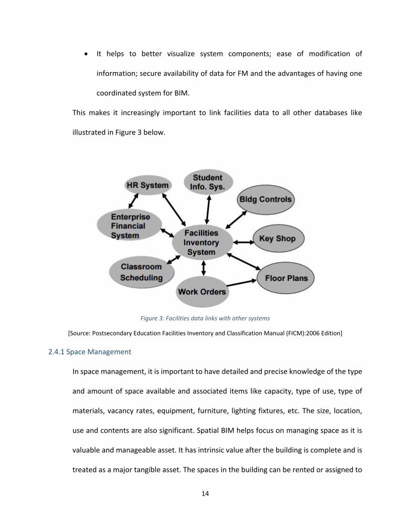
It helps to better visualize system components; ease of modification of
information; secure availability of data for FM and the advantages of having one
coordinated system for BIM.
This makes it increasingly important to link facilities data to all other databases like
illustrated in Figure 3 below.
Figure 3: Facilities data links with other systems
[Source: Postsecondary Education Facilities Inventory and Classification Manual (FICM):2006 Edition]
2.4.1 Space Management
In space management, it is important to have detailed and precise knowledge of the type
and amount of space available and associated items like capacity, type of use, type of
materials, vacancy rates, equipment, furniture, lighting fixtures, etc. The size, location,
use and contents are also significant. Spatial BIM helps focus on managing space as it is
valuable and manageable asset. It has intrinsic value after the building is complete and is
treated as a major tangible asset. The spaces in the building can be rented or assigned to

15
people and are often the locator of items like equipment, furniture, voice and data lines,
lighting fixtures, people, etc. This information can be quantified and made easily available
with a BIM model and can be accessed through schedules or spreadsheets within the
software and exported in a common file format for FM use. Different requirements can
be tailored as per the needs of the owner into the BIM guidelines which can be utilized
by FM through the lifecycle of the building for campus and space management.
2.4.2 BIM data for Operation, Maintenance, and Retrofits
Repairs and maintenance require a database of what exists and a timeline of when
equipment needs to be fixed, upgraded, or replaced. This can be obtained from an
accurate FM database. For example, an upgrade to the carpets in the building might entail
replacing the old with new, characteristics of the carpet, links to manufacturer sites and
specifications like thickness and materials can be in the BIM. Maintaining a BIM file with
updates for facility management data are like maintaining to an actual facility. As the
different components are repaired, replaced, removed, these changes will need to be
reflected in the model. In fact, these updates can be easily done in the model prior to any
work undertaken to calculate quantities, visualize how the new retrofits look in the
existing building. The model gives the user the levy to work different permutations
combinations before a final decision is made. Once these changes reflect in the BIM file,
it can be used as an accurate as-built for future use.
2.4.3 Populating the FM database from a Building Information Model
Once a model that is fully populated with all the building components, facility managers
and owners will have a much more powerful tool to manage a building. The model can

16
become a complete repository of building information and data that formally had no
shared, centralized collection point. The FM staff can extract this information to populate
their CMMS systems.
The Facilities department does not operate in isolation. Their processes and data are
always used in conjunction with academic, financial, human resource and student data.
The Facilities Management department classifies spaces consistent with those specified
under categories in the Facilities Inventory and Classification Manual (FICM). The manual
is a tool to help institutions/universities, and describes standard practices for initiating,
conducting, reporting, and maintaining an institutional facilities inventory. Once
completed, this facilities inventory will enable an institution to measure the ability of its
space to meet its current programs, assess the current operation costs of its facilities
(maintenance, utilities, cleaning, etc.), and then begin to plan for future space needs
(FICM, 2006).
The categories encompass all types and uses of assignable and non-assignable areas
found in campus buildings. A standard coding system is intended to provide meaningful
and comparable summary data that assists all institutions to map comparable spaces to
the same category. All assignable spaces are classified into 1 of the 10 major assignable
use categories and all non-assignable space are classified into 1 of the 3 major non-
assignable use categories listed in Table 1 below. This space use coding is intended to
identify only the specific architectural use of an individual space; it does not help tracking
other conditions or circumstances about a space.

17
Table 1: BIM guide project concept
[Source: FICM, 2006 Edition]
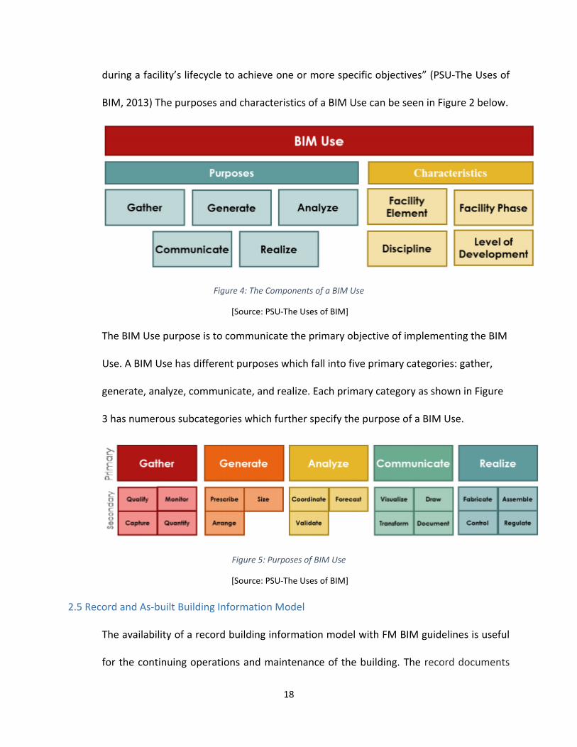
BIM uses are classified based on the purpose for implementing BIM throughout the life
of a facility. A BIM use is defined as “a method of applying Building Information Modeling
18
during a facility’s lifecycle to achieve one or more specific objectives” (PSU-The Uses of
BIM, 2013) The purposes and characteristics of a BIM Use can be seen in Figure 2 below.
Figure 4: The Components of a BIM Use
[Source: PSU-The Uses of BIM]
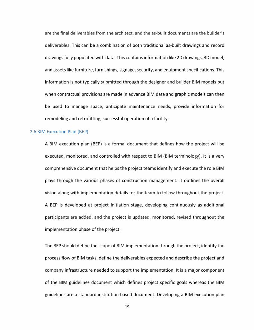
The BIM Use purpose is to communicate the primary objective of implementing the BIM
Use. A BIM Use has different purposes which fall into five primary categories: gather,
generate, analyze, communicate, and realize. Each primary category as shown in Figure
3 has numerous subcategories which further specify the purpose of a BIM Use.
Figure 5: Purposes of BIM Use
[Source: PSU-The Uses of BIM]
2.5 Record and As-built Building Information Model
The availability of a record building information model with FM BIM guidelines is useful
for the continuing operations and maintenance of the building. The record documents
19
are the final deliverables from the architect, and the as-built documents are the builder’s
deliverables. This can be a combination of both traditional as-built drawings and record
drawings fully populated with data. This contains information like 2D drawings, 3D model,
and assets like furniture, furnishings, signage, security, and equipment specifications. This
information is not typically submitted through the designer and builder BIM models but
when contractual provisions are made in advance BIM data and graphic models can then
be used to manage space, anticipate maintenance needs, provide information for
remodeling and retrofitting, successful operation of a facility.
2.6 BIM Execution Plan (BEP)
A BIM execution plan (BEP) is a formal document that defines how the project will be
executed, monitored, and controlled with respect to BIM (BIM terminology). It is a very
comprehensive document that helps the project teams identify and execute the role BIM
plays through the various phases of construction management. It outlines the overall
vision along with implementation details for the team to follow throughout the project.
A BEP is developed at project initiation stage, developing continuously as additional
participants are added, and the project is updated, monitored, revised throughout the
implementation phase of the project.
The BEP should define the scope of BIM implementation through the project, identify the
process flow of BIM tasks, define the deliverables expected and describe the project and
company infrastructure needed to support the implementation. It is a major component
of the BIM guidelines document which defines project specific goals whereas the BIM
guidelines are a standard institution based document. Developing a BIM execution plan

20
helps the project and project teams achieve the following value (BIM Planning Guide for
Facilities Owners, 2013):
It helps organizations and participating parties understand the roles and
responsibilities in the implementation process.
It assists all parties in clearly understanding and communicating strategic goals
for implementing BIM on the project.
It helps the team tailor an execution process that is well suited for best business
practices and organizational workflows.
The plan guides any future parties with detailed description of the process.
It is beneficial in drawing contracts and language essential such that all project
parties fulfill their obligations.
Through this process, ultimately the entire team adds value through the increased level
of planning by reducing or eliminating unknowns in the implementation process, thereby
reducing the overall risk to all parties and the project itself.
2.7 Building Information Model – FM Database links
The BIM model can be used to efficiently provide information to continuously update the
FM database and for managing assets. Information with detailed specifications can be
made available in the form of spreadsheets, and the facilities can be connected to BIM.
As a part of efficiently updating the database of assets, the Construction Operations
Building Information Exchange (COBie) approach was developed to address the lack of
standardization and organization of the several documents that are handed over to the
21
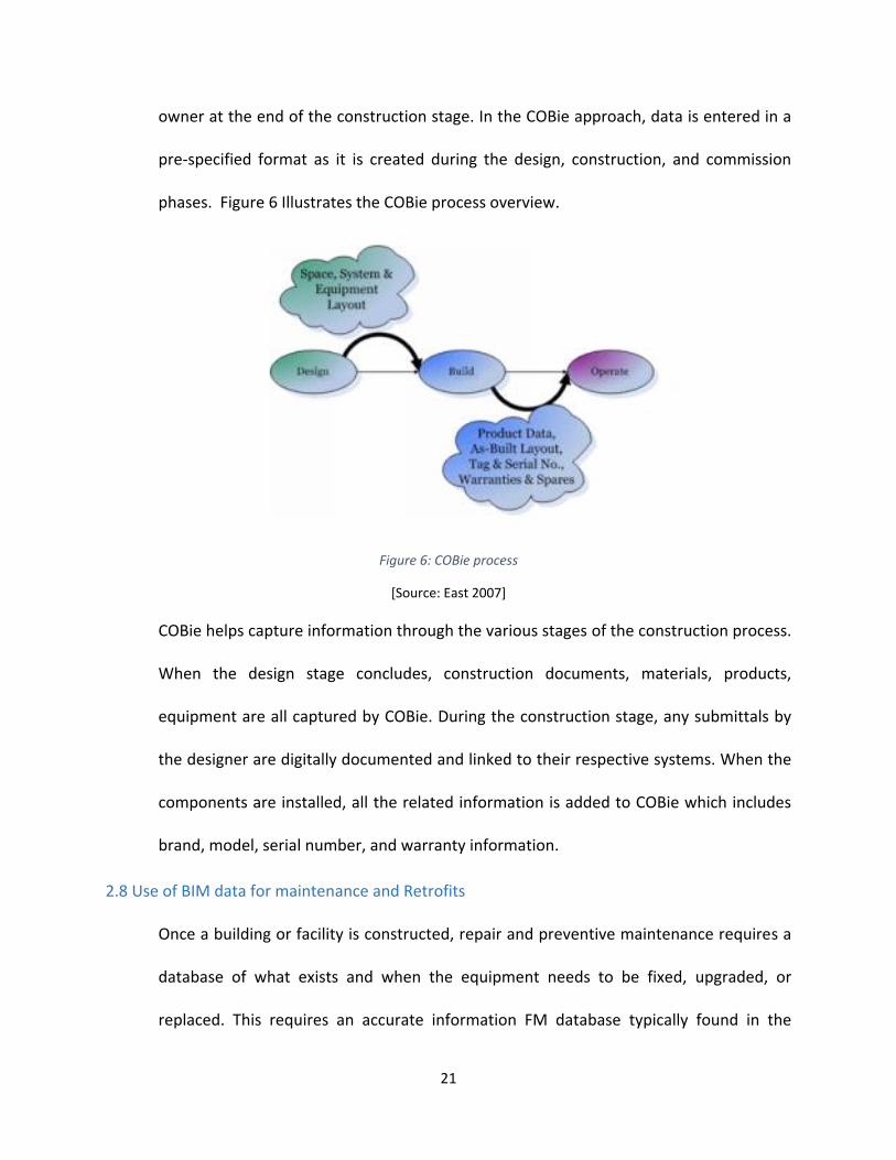
owner at the end of the construction stage. In the COBie approach, data is entered in a
pre-specified format as it is created during the design, construction, and commission
phases. Figure 6 Illustrates the COBie process overview.
Figure 6: COBie process
[Source: East 2007]
COBie helps capture information through the various stages of the construction process.
When the design stage concludes, construction documents, materials, products,
equipment are all captured by COBie. During the construction stage, any submittals by
the designer are digitally documented and linked to their respective systems. When the
components are installed, all the related information is added to COBie which includes
brand, model, serial number, and warranty information.
2.8 Use of BIM data for maintenance and Retrofits
Once a building or facility is constructed, repair and preventive maintenance requires a
database of what exists and when the equipment needs to be fixed, upgraded, or
replaced. This requires an accurate information FM database typically found in the
22
Computer Maintenance Systems (CMMS’s). For example, if a building requires changing
of lighting fixtures, the location of the fixtures, characteristics of the fixtures, and links to
manufacture sites typically available for work order execution can all be fed into or
extracted from the BIM model. Maintaining a BIM file for facility management requires
simultaneous updates as the maintenance of the actual building. If any components are
replaced, repaired, removed, those changes will need to be updated in the BIM file.
In the case of WPI, majority of the campus buildings were built before BIM was
implemented on campus. BIM models can be linked to CMMS when new buildings are
built or when BIM models are created for the existing buildings.
2.9 Need for a BIM guide
The utilization of BIM beyond design and construction is extremely important to provide
an owner value for a facility through efficient FM operations. Currently, utilization of BIM
at FM stage is not fully realized and is a relatively new concept for the FM department at
WPI. The purpose of the BIM guide is an effort to bridge the existing gap by standardizing
processes and integrating the facility operations in the design stage for new buildings. For
existing buildings, BIM models should be created and data needs to be integrated for
facility management. This will help extend the implementation of BIM into the later stages
of the project life cycle. The project life cycle includes planning, design, construction,
operation and maintenance, and decommissioning. Through BIM, it is possible to provide
a framework to develop data rich models. These models will benefit a facility and serve
as gateway to provide any time access to insert, extract, update, and modify data by all
participants involved in the life cycle.
23
Integration of BIM through the design and construction process and extending it through
the lifecycle of the project has the following benefits:
Budget Management
Contract Management
Decision Making
Information Management
Material and Equipment Management
Project Management
Quality Management
Resource Management
Risk Management
Safety Management
Schedule Management
Value Management
2.10 Objectives of the guide
Since 2005, WPI has been using some components of BIM in the design and construction
of new facilities and has extended BIM uses to support facilities and space management
in some of the existing buildings. An effort to implement BIM has been extensively
observed and studied through student projects and theses on campus. The students have
worked with the FM department on various projects but current BIM practices for WPI
campus are not consistent and sustainable in their current form. To date, no formal and

24
systematic approach has been established in documenting and organizing processes for
the different BIM uses on campus.
The main objective of this guide is to provide the requirements and technology for WPI’s
use of BIM for facility management. It aims to meet several purposes:
Identify the work processes and information requirements for facility management.
Determine the information required before, during and after construction.
Evaluate different methods to record and capture information updates.
Define the scope of information that should be included or updated at the end of a
project.
Identify technology requirements to access and update the BIM data by the architects,
contractors, and facility managers.
This guide will help to provide better maintenance of the campus and coordinate the
different facilities on site. Whether it is new construction or an existing old building
on site, these guidelines will list the scope of work and deliverables for projects on
campus.

25
3 METHODOLOGY
To attain the objectives of this research, the following methodology was identified for
delivering a successful BIM guide:
Conduct a case study on the Facilities Management process.
Conduct in depth case studies of existing university BIM guides and review existing
documentation published by other universities.
Develop a proposal for a BIM guide exclusively for WPI.
Validate the contributions of the proposed BIM guide.
3.1 Conduct a case study on the Facilities Management process
One of the key aspects of proposing a BIM guide is to have a good understanding of the
Facility Management processes and operations. To achieve this, an in-depth case study
consisting of two major parts was conducted on campus at WPI.
The first part of the case study analyzed the Facilities Management organization and
identified the different activities undertaken by the department. To facilitate this task, a
study of the organizational chart and interactive meetings with the department were
conducted. This helped better understand the relevance and importance of BIM in the
current processes at WPI. It gave an insight into the Computerized Maintenance
Management System (CMMS) system that the department utilizes for campus
management. The main goal of this study was to identify how BIM has been a part of
campus planning and management in the past and how relevant is it to the department
moving forward.
26
The second part of the case study was to study the role of BIM in completed and ongoing
projects on campus. The WPI Recreation and Sports Center, a facility completed in 2012
was selected to study a completed project on campus that, to a certain extent used BIM
in the design and construction of this facility. The key idea was to analyze how the BIM
process was implemented by the architect and the construction manager for the design
documentation and coordination, as well as for providing information delivered at close-
out for the building. This information was used to analyze the relevance of BIM and its
benefits to the FM department.
For an ongoing project on campus, a case study was conducted on the Foisie Innovation
Studio. This looked at the benefits of utilizing BIM as a tool for managing and facilitating
construction from the design phase onward. The main purpose of this task was to identify
the benefits of incorporating BIM early in the project that could benefit the FM
department later for operation and maintenance.
To date, 25 BIM models were created as part of student projects from data available.
The following buildings were modeled in detail after verifying information in field:
Project Center
Washburn Shops
Salisbury labs
Institute Hall
Sanford Riley Hall

27
Founders Hall
The attributes that were of main interest to the participating facilities staff were linked
to the spaces in the BIM.
3.1.1 Interviews
A set of interviews was conducted in which six (6) key members of the facilities
management team were consulted to identify their requirements for information and to
identify potential ways in which they would like to utilize BIM for facilities management.
Their responses about the need and relevance for the development of a BIM guide for
WPI were recorded – Table 2 (Pg. 94) summarizes the results of these interviews.
3.1.2 Research
Worked with the FM department to understand their needs and requirements.
Consultation through presentations and interviews helped identify goals and draw a work
plan to move forward with the research. Collected data on the case studies and studied
successful BIM implementation for large campuses/universities. Identified best practices
and BIM information relevant to WPI.
3.1.3 Survey
Any work done on campus with respect to BIM has been through student projects done
with the Facilities Department. A survey of these existing measures implemented on site
through student projects was conducted to review the nature and depth of the work
undertaken.

28
3.1.4 Proposal
The survey not only helped identify what was implemented on campus, but also
determine the nature of problems, identify requirements and what proposals/guidelines
can be identified for WPI. The proposal would address specific BIM needs.
3.1.5 Priorities
Developing the proposed content required setting what actions are most important and
prioritize goals as all prior solutions for all findings from the research may or may not be
incorporated in the proposed guide.
3.1.6 Design
The final step was to develop and design the BIM-guide that met the WPI needs and
requirements in assisting BIM implementation on campus for facility management.
3.2 Conduct a case study of existing university BIM guides
A case study of existing university BIM guides was conducted to understand the different
uses of BIM, fields of applications and the targeted users through five university BIM
guides that have been successfully adopted and implemented. The key method of the
research was to use a template approach to determine a baseline of common fields from
majority of the BIM guide documentation available. A template approach was used to
structure the review of a document and allows for systematic comparison of the contents
and scope of different guides.
Due to the lack of standardization at national or international level (NBS International BIM
Report 2016), this analysis is used to harmonize the content of the guides at various levels:
29
Different uses of BIM and fields of applications and the targeted users.
Map content by the given chapters to derive a common table of contents. This
establishes a common structure of framework which aids the process of creating a
new BIM guide.
Mapping definitions and terminologies; these keyword help identify and standardize
terminology that contributes to establish a measure guide with consistent or
standardized terms, definitions, and structure.
The study helped map the contents by the given chapters and derive a common table of
contents for the proposed BIM guide. Though the guides were different in some ways,
several commonalities were observed in all five. This helped establish a common
structure of framework which aided the process of creating the new BIM guide. It also
helped map common definitions and terminologies; these keywords helped identify and
standardize terminology that helped contribute to the made to measure guide with
consistent, standard terms, definitions, and structure.
3.3 Develop a proposal for a BIM guide exclusively for WPI
The detailed analysis of the case studies helped identify the following common categories
of information type:
Standards
Contracts specified (including technical specifications)
Roles and responsibilities of involved parties
Tools & technology

30
Modeling guidance
This helped identify how to plot content towards adopting relevant data and mapping the
common table of contents for the proposed BIM guide. The outcome was to propose and
develop BIM guide for WPI facilities management department.
3.4 Validate the contributions of the proposed BIM guide
For the purposes of technical feasibility and reliability, the BIM guide proposed in this
research was validated in two parts: The first part validated the document feasibility by
looking at the value added using BIM guidelines by applying the proposed concept to one
of the pilot projects on campus for FM purposes. The Project Center building was selected
for the validation process.
The second part was a documented form of feedback from the facilities management staff
through presentations and personal interviews. Six members of the facilities
management team participated in the interview process and completed a questionnaire
(see Appendix A). The interviews addressed various questions like need for the guide,
feedback on the proposed contents of the guide, identify missing content, potential users
of the guide, relevance of the guide for FM for new and old buildings, etc.

31
4 WPI FACILITIES MANAGEMENT PROCESS
The key to propose a successful BIM guide for the WPI FM department is to understand
the FM processes and operation. To achieve this, a study was undertaken to better
understand what are the main functions and organization of the FM department and how
is the FM department currently using BIM in new and existing projects.
4.1 The Facilities Management department
This section looks at the organization of the FM department, their efforts to implement
BIM on campus and the integration of BIM in the construction process for existing and
new construction.
Facilities Management department organization:
Worcester Polytechnic Institute (WPI) was founded in 1865 and houses 14 academic
departments that offer over 50 undergraduate and graduate degree programs. The
campus is located on a 95-acre site set in an urban context in Worcester city. It is a private
institution with an enrollment of 4,320 undergraduate students, 2,063 graduate students
and faculty strength of over 450 members. (WPI 2016)
The campus has 36 major academic, residential, recreational, and administrative buildings
encompassing nearly 2,394,471 gross square feet (GSF) of space. In addition to the
buildings on the main campus, WPI owns 38 houses and a 24-unit apartment building in
the neighborhood (WPI STARS report, 2015).

32
The Facilities Department plays an important role in the operation and maintenance of
the campus on a day-to-day basis. Their following mission statement conveys the main
functions and commitment of the department towards the WPI community.
“The mission of the Facilities Department is to provide a safe, clean, properly maintained
environment for the WPI community, in support of academic and social activities.
Facilities staff will furnish the highest quality service, with the highest level of
professionalism.” (WPI Facilities Department)
The organizational chart of the department as its highest level is shown below in Figure 7
Figure 7: Facilities Department Organization Chart

33
4.2 BIM uses for FM at WPI: Existing Facilities
Space Management, one of the major functions of the FM department, is an activity that
is naturally supported by BIM. WPI first adopted BIM in 2005 and since then it has been
gradually explored and implemented in various aspects of design, construction, and
facilities management of some buildings on campus as well as for academic purposes.
WPI adopted the use of Revit to build BIM models of existing and new buildings on
campus to assist with better campus management. To date there are 25 BIM models of
campus buildings that have been mostly developed as student projects to different
degrees and for different purposes. These models contain information that can be used
for space management, operation and maintenance, attributes assigned to spaces and
the location of MEP equipment.
The BIM models were intended to be used during the lifecycle of a construction project,
operation, and maintenance. Repeatedly, facilities department has acknowledged the
benefits of utilizing BIM for FM. For example, an incident that occurred during a baseball
match at Harrington auditorium broke a fire sprinkler causing water leakage.
Unfortunately, it took the facilities department a while to locate the shut off valve causing
inconvenience to everyone. BIM data could have helped located these utilities and shut
off valve to respond to the emergency faster.
The development of BIM models as a part of student projects was an effort to build
models of the existing buildings on campus. These buildings did not necessarily have
updated plans and drawings to begin the BIM process but the models were built off what
was available. The BIM models created by the students contain primarily the architectural

34
floor layouts and in some cases the structural frame of the building. In 2013, the FM
department initiated a more aggressive use of BIM and selected few buildings to study
the benefits of application of BIM in more detail. To start with, small and less complex
buildings like the Project Center was selected and modeled.
4.2.1 Work done so far
The buildings worked on so far on campus are the Project Center, Washburn Shops,
Salisbury labs, Institute Hall, Sanford Riley Hall, and Founders Hall. These are existing
buildings on campus, and BIM models were developed to better manage and maintain by
the Facilities Department.
Through interviews with FM staff, the following attributes of interest were identified in
the BIM model to analyze the use of floor area. These attributes are:
Room Number
Gross Area
Net Usable Area
Net Assignable Area
Floor Finish
Number of Work Stations / Capacity
Use of the space (type)
Space assignation (department)
The Postsecondary Education Facilities Inventory and Classification Manual (FICM), 2006
Edition manual describes standard practices for initiating, conducting, reporting, and
maintaining a postsecondary institutional facilities inventory. Space is one of the primary

35
resources of an educational institution. The FICM provides definitions of building area
measurements, space use codes, room use codes and data useful for including in a
facilities inventory. It provides guidance on required and optional data for inclusion in a
facilities inventory, guidelines for developing a facilities database, suggests administrative
and analytic uses for facilities data and presents issues that emerge in collecting,
maintaining, and reporting facilities data. A more detailed description of these
parameters is presented in section 4.2.3. Figure 8 below shows the first floor of the
Salisbury Labs building BIM model indicating color coded space use categorization as per
FICM.
Figure 8: Sample view of Salisbury model

36
4.2.2 Process of creating BIM for buildings at WPI
The following procedure was adopted for all selected buildings on campus for the
implementation of BIM.
1. Retrieve and digitize the drawings for the buildings:
For the selected buildings, any existing CAD or paper drawings for the buildings were
used. There were differences between the available as-builts and the existing facility,
as renovations were mostly never updated on the drawings. The files were imported
into the BIM tool (Revit) and used as a starting point for the creation of the model.
The BIM tool used was Revit. Figure 9 below indicates how the 3D model is built from
the 2D drawing.
Figure 9: Migrating from CAD to Revit
[Source: https://i.imgur.com/aysVKsS.jpg]
2. Verify the dimensions of the available drawings:
The existing drawings were verified by taking field measurements of the actual facility,
using a laser distance meter. A tape measure was used where the use of the laser was
not feasible. Photogrammetry techniques and laser 3D scan part of the campus,
37
created by a third-party consultant, were also used to verify external measurements
of some of the buildings
The use of laser scanners to measure a building is a new and emerging technology,
though expensive but very effective and accurate. It uses a device, shooting beams of
light, and measuring the distance and angle of the reflection of light, which can
perform thousands of measures per second, and each measure is a referenced point
that after processing can be combined in a point cloud creating a three-dimensional
representation of the facility formed by points. The model produced, once the point
cloud file is imported into the BIM model has high accuracy and is especially
convenient for modeling existing buildings and their MEP systems, exterior envelopes,
etc.
3. Develop the model:
After verifying the dimensions of the drawings, the model was created which included
the geometry and basic information of the modeled elements. The model included
walls, floors, fenestrations, roofs, and stairs. No structural, mechanical, plumbing or
electrical systems were modeled. These systems were indicated and their locations
were mapped for representation purposes.
4. Create spaces:
The models indicated rooms were created representing the different spaces in the
facility enclosed by walls and floors. The space calculation was set to volume,
therefore not only the area of the room is available but also the volume
5. Attach important information to the model rooms:

38
The different information associated with the rooms was integrated in the model.
This information included area, location, floor finishes, ceiling finishes, room
capacities, and the location of the connection of the building with external MEP
utilities. This information was documented directly from the facility at the same time
the dimension verification took place. The FICM classification was used to classify the
use of space.
6. Finalize BIM model:
The actual BIM model was created in Revit and a viewable version of the 3D model in
DWF format as well as 2D floor plans using a drawing sheet template in PDF format
were created and distributed to the users. Both formats were not editable. The DWF
file can be used for viewing and interrogating the model. The following information
was included on the PDF drawing sheet template:
Original issue date
Sheet number
Title - description of drawing and location information.
Location information should include all building, floor, and room numbers as
applicable.
Scale of the drawing.
Revision history - as applicable.
WPI Project number.
Information on who has drawn the drawing and who has reviewed the drawing.
An example of the final drawing produced is shown in Figure 10 below.

39
Figure 10: Sample of the drawing sheet

40
7. Uploading and storing BIM files:
The final BIM files were stored on the SharePoint website:
https://sharepoint.wpi.edu/research/bimfm/documents/
SharePoint is a collaboration tool that allows teams to share documents, contacts,
calendars, and other relevant information on one website. The Facilities Department
helped provide access to the FM BIM files and one could use their WPI credentials to
log in to the portal. All BIM related information/data was stored under the student
projects tab and this information was accessible only to authorized personnel’s. The
SharePoint application was also available to download on all Android and Apple
devices through the App stores making this data easy accessible. The app was free to
download and the user could view all pdf files available on SharePoint on their mobile
devices on the go.
4.2.3 Different model parameters
The model parameters specified above were the key information that the WPI Facilities
department found most relevant. The selection and relevance of these were derived from
the interviews and interactions with the facilities department staff.
Department: A department consists of various room that encompass the different
spaces that were included in BIM. This was used to allocate costs, return on
investment analysis by the facilities department. The department listing
information was obtained from the buildings directory.
Room numbers: The room numbers were required for room identification and the
WPI numbering system was adopted. The room number is a three-digit number

41
with the first number indicating the floor number and the other two digits
indicating the room on the floor. These room numbers were verified with the
actual ones in the facility. The room numbers at WPI are always three digits, the
only exception being Gateway Park, where there are four numbers. (WPI Acronym
Dictionary)
Room areas: The room area is an important aspect of space management. It helps
to understand the allocation of spaces for various uses such as, departments, staff,
students. The room areas were calculated directly from the model having verified
the dimensions beforehand. These areas were calculated based on the clear
interior dimensions of the rooms. This information is of great value not only for
the FM department but for other WPI academic and administrative purposes as
well.
Floor finishes: Floor finishes were another attribute added to the BIM which would
mainly be used for custodial coordination. This also helped identify the floor
finishes assigned to the spaces in a facility.
Ceiling finishes: Ceiling finishes served the same purpose as the floor finishes.
These attributes helped update information that was outdated as there was
renovation done over the years on these buildings.
Room use: The room use attribute helped determining room capacities, efficiency
rating and future possible uses. The projects implementing BIM at WPI used the
WPI standard for door tags and the Post-Secondary Facilities Inventory and
Classification Manual (FICM) (National Center for Educational Statistics, 2006) for
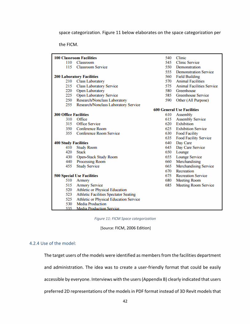
42
space categorization. Figure 11 below elaborates on the space categorization per
the FICM.
Figure 11: FICM Space categorization
[Source: FICM, 2006 Edition]
4.2.4 Use of the model:
The target users of the models were identified as members from the facilities department
and administration. The idea was to create a user-friendly format that could be easily
accessible by everyone. Interviews with the users (Appendix B) clearly indicated that users
preferred 2D representations of the models in PDF format instead of 3D Revit models that
43
could be accessed on a mobile device such as a tablet, computer, or a smart phone. They
expressed that the 3D model representation was good to visualize the project but
navigating and managing the model required knowledge and expertise of the software.
The PDF format of the files only permitted viewing the files which ensured that the files
would be non-editable. These files would be accessible through the SharePoint website
and access would be controlled.
4.2.5 Maintenance of the model
To ensure successful and continuous implementation of BIM, updating information on
the model is important. Every time a facility undergoes renovation, the model must be
updated. This would require updating the last and latest version of the model available
following the proposed guidelines listed in the WPI BIM guide in Appendix C. The FM
department must appoint an individual, who could be a designated FM staff member,
student assistance or third party consultant with the knowledge of BIM and the work
done at WPI to update the models. These models should be updated periodically to
record for any updates, changes, retrofits. An up-to-date BIM model will help in
renovation, quantity take off, cost estimation, campus planning, future construction,
operation, and maintenance. The BIM software, Revit can be used to update the models
and make information available to users.
4.3 BIM uses for FM at WPI: New facilities
The section presents two case studies to illustrate the existing BIM processes adopted
and implemented at WPI on their new buildings. Two buildings were selected to complete
the study, one recently completed building and another building under construction. The
44
completed building was the WPI Sports and Recreation center and the building under
construction was the Foisie Innovation Studio. Information on both these projects was
obtained from student project work done for both the building on campus for BIM.
4.3.1 Case Study 1: WPI Sports and Recreation Center
The WPI Sports and Recreation Center is a 140,000-square foot recreational, educational,
and environmentally friendly facility. It contains a pool, a fitness center, a four-court
gymnasium, an indoor running track, rowing tanks, racquetball and squash courts, dance
studios, and offices and meeting spaces for the coaches and staff of the Department of
Physical Education, Recreation, and Athletics. The Sports & Recreation Center is home to
the wrestling team as well as the practice facility for men's and women's rowing and
varsity team training.
Construction of the WPI Sports and Recreation Center was completed in 2012. This was
the first project in which the architect submitted a BIM model but only for the purposes
of generating the construction documentation (See Figure 12). The student project
(Alvarez, 2014) explored the use of BIM as a tool to provide continuity for the flow of
information from the design/construction phase to the operation and maintenance phase
by the WPI Facilities Department. Through student academic projects, the importance of
implementing BIM A model was created to demonstrate the capabilities of BIM for
architectural, structural data, for storage and retrieval of closeout documents, operations
and maintenance manuals, all information critical for the Facilities department.
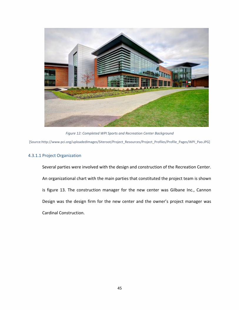
45
Figure 12: Completed WPI Sports and Recreation Center Background
[Source:http://www.pci.org/uploadedImages/Siteroot/Project_Resources/Project_Profiles/Profile_Pages/WPI_Pao.JPG]
4.3.1.1 Project Organization
Several parties were involved with the design and construction of the Recreation Center.
An organizational chart with the main parties that constituted the project team is shown
is figure 13. The construction manager for the new center was Gilbane Inc., Cannon
Design was the design firm for the new center and the owner’s project manager was
Cardinal Construction.

46
Figure 13: External Organization Flowchart
[Source: Trevor Bertin et al, 2011]
4.3.1.2 Architectural and Structural Design
The availability of the BIM model for the project gave WPI students and faculty an
opportunity to explore structural materials and design alternatives whilst providing
calculations and cost for each alternative. This helped identify the most cost effective
alternative in the long term. The use of 3D modeling helped visualize design features and

47
evaluate what was aesthetically most pleasing at the early stages of project development.
Though the record model was developed using Autodesk Revit, the file was viewable
through Autodesk Design Review software. The record model did not contain the design
changes that took place during construction. However, having the 3D model in DWF
format gave easy access and operability to the Facilities Department as it was a user-
friendly interface that didn’t require intensive training to use. The DWF files associated
with the software were significantly smaller that the Revit RVT files. This allowed for
convenient storage and transfer of information.
4.3.1.3 Cost and Schedule
Based on the architectural BIM, the construction manager created a 3D Navisworks model
to coordinate the MEP work prior to the execution of this work. This allowed the
contractors to anticipate system clashes and prepare cost estimates for the different
alternatives. This helped review and compare costs to determine the most cost efficient
solution. Also, schedule estimates for each of the alternatives were produced using
information obtained from the BIM model.
4.3.1.4 Facilities Management
The operations and maintenance (O&M) manuals and other closeout information were
conveyed through the 3D as built drawings that were relevant for FM. The model included
MEP systems, structural and architectural elements. A PhD thesis (Alvarez, 2014) was
dedicated to study what information from the BIM model was of use to the FM and how
the information contained in the BIM models could be used for FM purposes. The main

48
contractor delivered this information in a digital format on a DVD and was organized by
CSI trades. The package included a total of 540 files, however, only 442 files contained
useful information. It was observed that there was redundancy in the information in
terms of drawings stored as PDF and DWG format. The submitted drawings included
Bidding and As-Builts documents showing some inconsistencies in room numbering and
levels. The names of the files were very short with no clear indication of what was
included in the drawing.
The remaining documents comprised of Operations and Maintenance (O&M) Manuals,
Specifications, Warranties and Guarantees. However, these documents were not
organized, were different types and not indexed making future queries for information
very time consuming. A BIM model developed by the designer only for project
visualization, presentation purposes and production of coordinated 2D drawings was also
handed over on this project. This original model was later updated by WPI students who
modified the original numbering assigned by the designer to reflect the final assigned
room numbers. Some elements that were not relevant to FM were filtered out thus
creating a lighter version of the model for their use. The model parameter was modified
to meet the requirements proposed by the FM department and was successfully
structured with the added parameters in accordance with the IFC standard, combined
with COBie and Owner specifications and linked to PDF scanned documentation using the
proposed model view definition. The students research proposed an approach for making
the documentation available for the FM users through a shared folder. However, much
work on classifying and sorting information was still required to make the system truly

49
functional. In addition, recommendations were made for structuring and standardizing
the file management system. Overall, these studies provided in-depth understanding of
the BIM based process and of the information needed by FM.
4.3.2 Case study 2: WPI Foisie Innovation Studio (New ongoing project)
The Foisie Innovation Studio will consist of residential and academic spaces with a total
area of 78,000 square feet, with 40,000 square feet of academic space and 38,000 square
feet of residential space. As WPI is getting more involved in BIM and having used BIM in
the past on other projects, BIM would be an important aspect of this project.
The design and construction of the Foisie Innovation Studio (See Figure 14) is now being
used to further advance the use of BIM at as a tool, that among other purposes, will
coordinate the creation of information during design and construction transferred to the
FM department when the construction is complete in 2018.
Figure 14: Proposed WPI Foisie Innovation Studio

50
[Source: https://www.wpi.edu/sites/default/files/2016/08/31/Foisie%20Renderings.jpg]
4.3.2.1 Background
WPI was founded in 1865 by two entrepreneurs from Worcester, Massachusetts, and has
held true to its roots by maintaining a focus on innovation and collaboration. As
illustrated by the school’s motto, WPI students are encouraged to learn not only in the
classroom, but by working on real-world projects. Boynton Hall and Washburn Labs are
two buildings on campus that have served as symbols of the school’s philosophy. WPI is
now in the process of adding another building that will represent its philosophy:
Innovation. Following the razing of Alumni Gym, WPI is making way for the new Foisie
Innovation Studio that will complement the role of the Boynton Hall and Washburn Labs,
while symbolizing the new addition at WPI.
Originally, Alumni Gym was the hub for athletics on the WPI campus. With the
construction of the Sports and Recreation Center, there was no longer a need for this
facility. Although the Foisie Innovation Studio will cater to different academic needs, an
element of the Alumni Gym is retained to conserve the history of the gym building. The
grotesques on the gym building will be incorporated in the design of the new building (see
figure 15).
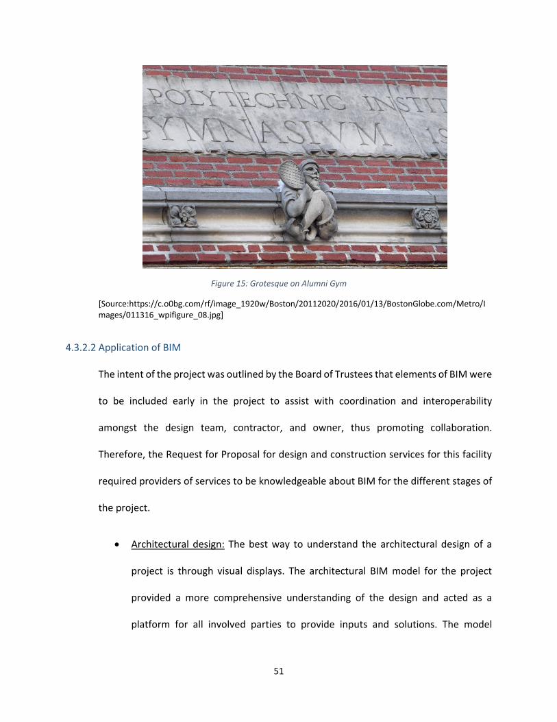
51
Figure 15: Grotesque on Alumni Gym
[Source:https://c.o0bg.com/rf/image_1920w/Boston/20112020/2016/01/13/BostonGlobe.com/Metro/Images/011316_wpifigure_08.jpg]
4.3.2.2 Application of BIM
The intent of the project was outlined by the Board of Trustees that elements of BIM were
to be included early in the project to assist with coordination and interoperability
amongst the design team, contractor, and owner, thus promoting collaboration.
Therefore, the Request for Proposal for design and construction services for this facility
required providers of services to be knowledgeable about BIM for the different stages of
the project.
Architectural design: The best way to understand the architectural design of a
project is through visual displays. The architectural BIM model for the project
provided a more comprehensive understanding of the design and acted as a
platform for all involved parties to provide inputs and solutions. The model
52
provided 3D views and architectural layouts with detailed floor plans which helped
foster a spatial understanding of the building and assisting with visualizing the
exterior appearance and context of the building with its surroundings. The
architectural and interior layouts play a crucial role in communicating information
about spaces, flow of people and activities through the building. The production
of these views can be accurately achieved with the use of BIM. The process of
finalizing these layouts and details goes through several iterations which can be
easily and efficiently managed through BIM. The model also enables to virtually
walk through the building which helps make comparisons to 2D layouts, thus
identifying errors, additions, and omissions as the design progresses.
Structural design: The structural component of the BIM software works in relation
to the architectural component making it convenient to identify clashes between
the architectural and structural members. The early detection of these clashes is
an important aspect of the BIM as it helps deliver an accurate structural frame
saving enormous amount of time and man-hours spent on numerous calculations
and analysis after. The clash detection helps avoid potential design errors in field
thus reducing construction costs to mitigate, avoid schedule delays and fewer
requests for information (RFI’s).
Project Scheduling: One of the key aspects of the project was to create a schedule
for the construction of the building that would verify the feasibility of the proposal
within the constraints set by WPI board of trustees. With the start and end date
defined, the BIM helped with identifying and arranging the activities in a logical

53
sequence. Primavera software assisted with a network diagram which assembled
this information and helped determine the critical activities for the execution of
the project. Utilizing BIM in the development of the schedule saves the
contractors and designers a significant amount of time and money while also
helping them visualize the project. Users can produce a 5D model (cost + time)
which interconnects the 3D building model with cost and time. Scheduling
provides a work breakdown structure that organizes the construction activities
into sections/phases which simplifies the complex process of coordinating the
various activities done at the same time on different sections of the building.
Cost Estimating: The use of BIM allows for a deeper and more accurate analysis
and evaluation of the project even before the project breaks ground. The total
cost of the project was determined using a detailed breakdown of labor, materials
and equipment for demolition, architectural and structural work. Including the
cost in the 5D model helps visualize information in a comprehensive manner, it
allows all involved parties to understand how the building will come together and
what will be the value earned as construction progresses. It also illustrates how
each additional element adds to the cost of the building and helps track the
progress of the different phases of construction.
Facilities Management: Currently, a student MQP project is being conducted to
document the process by which WPI, the designer and the construction manager
involved in the construction of the Foisie Innovation Center are coordinating FM
related information from design to construction and handover to the owner

54
(Doskocil & Vaitkunas, 2017). The RFP documents used to invite design and
construction professionals for this facility contained an explicit statement
requiring BIM-based capabilities from these professionals. However, no specific
terms were included in the contract to define the scope and extent of the use of
BIM in the contract language. This resulted in a very interesting and collaborative
process among the owner, designer and construction manager that has “forced”
WPI to think critically as to what information, is really needed, what is not needed
and what is desirable. This has also provided an opportunity to examine the role
and desirable uses of BIM in this process.
Finally, specific information, structure, and content of data, including BIM-models
to be handed to the owner at the completion of the project has been clearly
defined. The students have played an important role in this process reviewing all
previous work conducted at WPI to-date and in promoting the dialog among
project participants. It has been agreed that the CM will incorporate building
attributes with their corresponding information into the BIM model that are of
primary interest to FM staff. This information, which is primarily of the MEP type
will be part of the record model and will be exported into a spreadsheet feeding
directly into WPI’s CMMS system. Subcontractors are required to provide this
information in their submittals.
4.3.3 Conclusion
The Department of Facilities purpose is to “broadly oversee the Institute’s physical assets”
and more specifically, “to maintain the adequacy and condition of capital assets, to

55
develop and periodically review policies, to advocate for new structures and rehabilitate
or remove older structures, and to make certain that adequate levels of funding exist for
facilities maintenance and operations.” (Department of Facilities, 2010)
Both the projects just reviewed looked at the benefits of BIM through student projects
and had no contractual agreements for the projects. The Foisie Innovation Studio project
has some contractual elements but were not clearly defined. However, the BIM
requirements established by WPI and the collaborative approach observed during the
design and construction of this project is further advancement of the use of BIM for FM
purposes. The key idea of implementing BIM on the project was to aid in the maintenance
and operation of a facility and its assets throughout the lifecycle of a building. This helped
assist in short-term operations like work orders, repairs, and long-term preventive
maintenance. The BIM record documents provided an accurate representation of the
physical conditions and assets of the building. It contained all detailed dimensions and
closeout information for the facility, MEP utility systems and equipment. This information
has assisted the Facilities Department in the following:
Maintain and update facility and equipment data.
Document and maintain O&M user manuals and equipment specifications.
Analyze and process work orders by retrieving the relevant information required
to complete the work.
Track usage, performance and maintenance of the facility and its assets.
Easily update the record BIM in case of upgrades, renovations, and maintenance.

56
Access BIM data digitally on desktops, mobile devices, tablets to locate issues,
monitor equipment, look up floor and ceiling finishes, and calculate areas without
physically visiting the facility.
Data is secure and can be accessed only by authorized personnel’s.
57
5. CASE STUDIES
A review of the material published by the five institutions was conducted to learn what other
universities around the country have done with regards to the development of BIM guidelines
at their institutions. Following are the five selected case studies (see Figure 16):
1. Case study 1: Indiana University (IU)
2. Case Study 2: Pennsylvania State University (PSU)
3. Case Study 3: Massachusetts Institute of Technology (MIT)
4. Case Study 4: Georgia Tech University (GTU)
5. Case Study 5: University of Southern California (USC)
[THIS SPACE HAS BEEN INTENTIONALLY LEFT BLANK]

58
Figure 16: Map of United States showing case study locations
The above case studies across United States were selected because of their
comprehensive nature and successful applications to different projects on their
respective campuses.
5.1 Identify information for Comparative Analysis
The approach followed to analyze these cases consisted in identifying common categories
of information type, implementation strategies and to plot that content towards adopting
relevant data for WPI. The idea was to use a template approach to determine a baseline
of common fields from majority of the BIM guide documentation available. A template
Case Study 4:
Georgia Tech
University
Case Study 1:
Indiana University
Case Study 5: USC Case Study 3: MIT
Case Study 2:
Pennsylvania State
University

59
approach was used to structure the review of a document and allows for systematic
comparison of the contents and scope of different guides. The different categories
broadly identified were standards, contracts specified (including technical specifications),
roles and responsibilities of involved parties, tools, technology, modeling guidance. Most
of these categories were relevant to all five BIM guides cases.
5.2 Review guides for common data fields
The selected guides were reviewed to capture common data fields which would provide
a method by which a comprehensive comparison would be possible. The various BIM
guides were very diverse in their content and the intent was to capture common elements
of the guides. The documents were split into two major sections with multiple sub-
sections:
Section 1: Guide Overview
Part a – Guide details
Part b – Intended use and audience
Section 2: Guide Content
Part a – Project planning
Part b – Technical specifications
Part c – Implementation processes
Part d – Supporting tools and software
Part e – Contractual aspects

60
5.3 Mapping a common Table of Contents
As much as the comparison of the guides to an overall scope was an important process,
narrowing down a common table of contents was crucial. Mapping of existing guides
helped achieve a table of contents that was relevant to WPI assisting with assembly of a
customized guide based on the contents found in these guides.
5.4 Case studies
This section reviews in detail each of the five documents and discusses in detail the
common elements found in all of them.
5.4.1 Case 1: Indiana University (IU)
Figure 17: Indiana University BIM Guide
The Indiana University (IU) architect’s office first issued IU BIM standards and project
delivery guidelines for projects $5 million and over in October 2009. These were later
updated in May 2012 for all IU projects.
61
The BIM Guidelines was an important document not only for the use of BIM at IU but also
for the research of BIM at college campuses. It was issued on Sept. 10th, 2009. The BIM
Guidelines mainly defined BIM roles and responsibilities of all the project participants
(owners, designers, engineers, contractors, O&M managers) in the project processes,
from pre-design to commissioning. The BIM Guidelines applied to IU A/E selections
advertised on or after October first, 2009 for the projects with total funding of $5M or
greater. (Indiana University Architect's Office 2009)
The BIM Guidelines had five major components: Chapter 1 (Requirements) defines
software requirements. The deliverable file format for all BIM project models is to be
.RVT (Autodesk Revit). Other software, include civil, geo-referenced, and collaboration
software must be interoperable with Autodesk Revit.;
Chapter 2 (Process) defines the submission process of two other important documents-
BIM Execution Plan and Integrated Project Delivery (IPD) Methodology Plan, the chapter
also defines and identifies model quality, energy requirements and design deliverable
schedule and milestones, from conceptual phase to construction documents;
Chapter 3 (Objectives and Application) defines the detailed BIM requirements for each
project phase, from Pre-Design to Commissioning. Each phase has subcategories such as
general, energy requirements, deliverables. Along with the BIM requirements, the
Guidelines establishes the methods as to how BIM is being transferred from the project
beginning to the ending;
Chapter 4 (Ownership and Rights of Data) claimed the ownership of all CAD files, BIM
files, and Facility Data belonged to IU;

62
Chapter 5 (Terminology) is a list of terminologies that would occur during the projects
and in the documentations.
5.4.1.1 BIM Execution Plan
The intent of this BIM Execution Plan is to provide a framework that will let the owner,
architect, engineers, and construction manager deploy building information modeling
(BIM) technology and best practices on this project faster and more cost-effectively. This
plan delineates roles and responsibilities of each party, the detail and scope of
information to be shared, relevant business processes and supporting software. (Indiana
University Architect's Office 2009)
The BIM Execution Plan shall be submitted to Indiana University by the design team within
thirty (30) days of contract award. The BIM Execution Plan is reviewed and approved by
Indiana University within fourteen (14) days after the submitting of the BIM Execution
Plan (Indiana University Architect's Office 2009). The BIM Execution Plan identified roles
and responsibilities of project participant in a BIM environment.
5.4.1.2 IU IPD (Integrated Project Delivery) Methodology Plan
The IPD Methodology Plan shall be submitted to Indiana University within thirty (30) days
of contract award. The IPD Methodology Plan will be reviewed and approved by Indiana
University within fourteen (14) days after the submitting of the IPD Methodology Plan.
The IPD Methodology Plan shall demonstrate a high level of integrated design while
identifying project team members and how they will interact with each other during the
project. This plan will include a critical path methodology on modeling procedures and
model information validation. Examples of IPD Methodology plans are, but are not limited
63
to, Reverse Phase Scheduling and Critical Path Modeling. The IPD Methodology Plan will
be a part of the final bid documents.
The template of IPD Methodology Plan is drafted by IU’s architect’s office. The intent of
the plan is to formalize a desire to see higher levels of integration within the design and
construction process than traditional methods.
5.4.1.3 IU BIM Proficiency Matrix
The BIM Proficiency Matrix is a matrix that was designed to measure the expertise of a
firm as it relates to using a BIM process on projects. It is used as one of the many selection
criteria during the selection process.
The Matrix is implemented using a spreadsheet file and contained eight selection
categories (A-Physical Accuracy of Model; B-IPD Methodology; C-Calculation Mentality; D
-Location Awareness; E-Content Creation; F-Construction Data; G-As-Built Modeling; H-
FM Data Richness), each category has four parameters. The total score of BIM Proficiency
Matrix can be achieved is 32. IU had defined 5 levels of BIM standards based on the scores
submitted by firms, the top level is “ideal”, scoring 29-32; the bottom level is “working
towards BIM”, scoring between 0-12. By March 19, 2010; 24 firms had submitted their
Proficiency Matrix to IU.
[THIS SPACE HAS BEEN INTENTIONALLY LEFT BLANK]

64
Table 2: Comparison of BIM Guides
5.4.2 Case 2: Pennsylvania State University
Figure 18: Pennsylvania State University BIM Guide
Pennsylvania State University (PSU) published BIM Project Execution Planning Guide
Version 1.0 (hereinafter referred to as the “Guide”) on October 8th, 2009. The Computer
Integrated Construction Research Program at the PSU developed the Guide, and was

65
sponsored by funding institutions such as The Charles Pankow, and the Pennsylvania State
University Office of Physical Plant.
The document provides development of a BIM Project Execution Plan by PSU. The
purpose of the BIM Project Execution Plan is to ensure that all parties are clearly aware
of the opportunities and responsibilities associated with the incorporation of BIM into the
project workflow. (Pennsylvania State University 2009)
This guide outlines a four-step procedure to develop a detailed BIM Plan. The procedure
is designed to steer owners, program managers, and early project participants through a
structured process to develop detailed, consistent plans for projects. The four steps
include:
1) Identify high value BIM uses during project planning, design, construction, and
operational phases;
2) Design the BIM execution process by creating process maps;
3) Define the BIM deliverables in the form of information exchanges;
4) Develop the infrastructure in the form of contracts, communication procedures,
technology, and quality control to support the implementation (Pennsylvania State
University 2009)
The first step is to identify the appropriate BIM uses based on project and team goals.
Twenty-five possible uses for consideration on a project. The Guide had provided a
method for identifying appropriate BIM uses for a target project.

66
The second step in the Guide is to design the BIM Project Execution Process, after each
BIM use is identified. The Guide developed a procedure to design the BIM Project
Execution Process. The process map developed in this step allows the team to understand
the overall BIM process, identify the information exchanges that will be shared between
multiple parties, and clearly define the various processes to be performed for the
identified BIM Uses. (Pennsylvania State University 2009)
After the process map has been developed, the next step would be defining the
requirements for information exchanges. The Guide presented a method for defining
information exchange. To accomplish the tasks, an Information Exchange Worksheet was
designed.
The final step in the Guide is to identify and define the project infrastructure for the BIM
Project Execution Plan. Nine categories were listed to support the infrastructure.
[THIS SPACE HAS BEEN INTENTIONALLY LEFT BLANK]

67
5.4.3 Case 3: Massachusetts Institute of Technology (MIT)
Figure 19: Massachusetts Institute of Technology BIM Guide
These guidelines at MIT are issued to promote the development of electronic drawings
and models suitable for use in the MIT Department of Facilities CAD and BIM
environment. Consistency and compatibility with existing MIT documents can only be
achieved when these standards are strictly adhered to. Electronic drawings produced and
submitted in accordance with these standards have significantly greater value to the
Institute. Architects, Engineers, and Contractors delivering documentation to MIT must
ensure these standards are reviewed, understood, and followed by those people
responsible for preparing electronic drawings and models. An Electronic File Q/A Checklist
has been provided to assist in the production of qualified documents.
5.4.3.1 Renovations and space change projects requirements
For typical Renovation and Space Change projects, the Designer is responsible for
submitting a complete set of construction documents (CDs) to MIT prior to the beginning
of construction. During construction, the Contractors are responsible for submitting

68
complete As-Built documentation to the project team as described in their contracts
(typically in both electronic and hardcopy formats) and Designers are responsible for
submitting the record documents to MIT based on this As-Built documentation.
Construction Documents and Record Documents submitted to MIT need to adhere the
criteria outlined in their document.
Designers that are not familiar with MIT's CAD requirements must meet jointly with the
MIT Project Manager and representatives from MIT’s Facility Information Systems (FIS) to
discuss specific project requirements prior to the development of any CAD
documentation. Designers should also take this opportunity to relay the project scope to
FIS so MIT can furnish Designer with existing drawings that will benefit the design team.
5.4.3.2 Capital project requirement
For typical Capital Projects, the Designer is responsible for submitting a complete set of
construction documents (CDs) to MIT prior to the beginning of construction. During
construction, the Contractors are responsible for submitting complete As-Built
documentation to the project team as described in their contracts (typically in both
electronic and hardcopy formats) and Designers are responsible for submitting the record
documents to MIT based on this As-Built documentation. Construction Documents and
Record Documents submitted to MIT need to meet the criteria outlined in this document.
Recognizing the diverse nature of capital projects, Designers need to meet jointly with
the MIT Project Manager and representatives of Facility Information Systems (FIS) to
discuss specific electronic requirements for the project in the early stages of project
startup.

69
5.4.4 Case 4: Georgia Tech University
Figure 20: Georgia Tech BIM Guide
The intent of the requirements of the guide is to create a prescriptive framework with
which BIM enabled teams will coordinate with Georgia Tech, the Board of Regents, the
Georgia State Finance & Investment Commission, and other applicable groups. This
document will allow all stakeholders to weigh the importance of each requirement on a
per-project basis. Through this collaborative effort, a final project-based set of
requirements and corresponding BIM Execution Plan will be issued based on what level
of BIM proficiency necessary for a given project.
Georgia Tech (GT) requires that all design and construction deliverables for projects be
created and derived from building information models, and expects that data associated
with the installed components of these facilities be reconciled and validated with the
construction deliverables. It is GT’s intention to reuse these models and data for facility
lifecycle management. Building information models shall be provided throughout the
design, construction, and close out phases along with an emphasis on corresponding

70
building data collection to be gathered using the Construction Operations Building
Information Exchange (COBie) to capture and record close out data.
COBie is an information exchange used to collect building data in spreadsheets that can
be tied to BIMs for efficiency and are used to assign building components unique naming
conventions outlined later in the document, so that information can be consumed and
validated through GT’s data management processes. Unique GUIDs, assigned in the BIM
tools, shall be maintained to support data in workflows that can then be used throughout
the design, construction, and building handover process.
Portions of this life-cycle oriented data format will be required for a variety of different
building information deliverables that will replace paper deliverables. The deliverables for
the Close-out in COBie format include, but are not limited to:
• Verification of the design solution against the Program for Design
• Scheduled building equipment/component lists
• Construction submittal register requirements
• Identification of installed equipment and all tagged building products
• Close-out deliverables
5.4.4.1 BIM Execution Plan (BEP)
The BIM Execution Plan is a living document that will continue to mature over the course
of project deliverable and milestones. The BEP will be reviewed and approved by GT
within fourteen days after the submitting of the BEP for review. The BEP also should
include assumed roles and responsibilities of the team even if that party has not yet been
identified, such as the construction team.

71
Design and construction teams will identify for themselves and the persons that within
their organizations responsible for managing the BIM(s), or portions of the BIM.
Collaborative aspects of the Integrated Project Delivery (IPD) approach are to be
harnessed in developing the BEP mentality.
5.4.4.2 Integrated Project Methodology Plan (IPP)
The IPP, integrated within the BEP, should demonstrate a high level of project integration
and technological workflows by identifying project methodology and modeling
procedures, quality control, and scheduling and model information validation. Examples
of IPP’s are, but not limited to, Reverse Phase Scheduling and Critical Path Modeling
conforming to level of development requirements. Constraints and model role
dependencies are described here. Although there is no template for the IPP plan, GT
encourages high level planning be incorporated in the BEP.
[THIS SPACE HAS BEEN INTENTIONALLY LEFT BLANK]
72
5.4.5 Case 5: University of Southern California (USC)
Figure 21: University of Southern California BIM Guide
The document defines the Design and Construction scope of work and deliverables for
using Building Information Modeling (BIM) on new USC construction projects, major
renovations and other projects as required by USC, based on a Design Bid Build form of
Contract.
BIM provides opportunities to vastly improve upon traditional methods of design and
construction coordination thereby reducing the potential for costly change orders,
providing multiple opportunities for owner review and participation by means of 3D
visualization of the project and specialty spaces, and reducing design and construction
schedules. In addition, BIM creates opportunities for reusing data for multiple purposes,
including the operation and maintenance of USC’s facilities. To achieve these ends, the
BIM must be structured to achieve the required purposes. The document describes USC’s
requirements for the production and use of Building Information Models (BIM) in the
design, construction, and maintenance of its facilities.
73
5.4.5.1 BIM Execution plan
As part of their respective proposals/bid submittals, the Architect and the General
Contractor must submit a BIM Execution Plan (BEP) describing processes and procedures
in place within their organizations used to coordinate and deliver the BIM’s and
associated data per the guidelines contained herein. USC will evaluate the BEP’s and
provide feedback to the successful bidder at the time of contract award, after which the
Contractor will have 2 weeks to make changes to the BEP and resubmit.
5.5 Conclusion
The five case studies reviewed helped in identifying specific concepts and materials that
would be relevant when creating the guide for WPI. Currently, WPI does not have any
mandatory guidelines that are required to be complied by the contractors, designers,
project managers or any other parties involved with regards to the use of BIM. There are
no set rules, regulations, or established requirements that they need to meet when
making a submission to WPI during the different stages of the project. The five case
studies were reviewed under the same fields and the results are summarized below in
Figures 23 and 24.
The five case studies helped identify the common categories of information type like:
• Standards
• Contracts specified (including technical specifications)
• Roles and responsibilities of involved parties
• Tools & technology
• Modeling guidance

74
Figure 22: University BIM guides comparison
[THIS SPACE HAS BEEN INTENTIONALLY LEFT BLANK]

75
Figure 23: University BIM guides comparison

76
6 WPI-BIM GUILDELINES DOCUMENT STRUCTURE, CONTENTS, AND VALIDATION
The following chapter explores the WPI-BIM Guidelines development approach. The
process involved a common framework for BIM guides and identified the information that
needed to be integrated into the BIM Model which would be useful for Facilities
Management. Having Identified the value of using BIM for Facilities Management the BIM
guide was developed for integrating and maintaining this information.
6.1 Research findings
The concept and process of developing the WPI-BIM guide has been illustrated in Figure
24 below. A review of the five university BIM guides helped identify different fields of
metadata, map a common table of contents, and utilize keywords that were crucial in the
development of the guide. Though the guides were different, a common framework of
information helped develop the made-to measure BIM guide for WPI.
Figure 24: BIM guide project concept
[Source: https://open.library.ubc.ca/cIRcle/collections/52660/items/1.0076411]
77
A table of contents relevant for the WPI BIM guide was mapped and following
chapters were detailed in the BIM guide. The major components of the guide
included information on the participating project teams, standards, contract
specific information (including technical specifications, roles and responsibilities
of involved parties, tools & technology, and modeling guidance.
Figure 25: Proposed WPI BIM guide
Chapter 1. Introduction
The first chapter introduces the concept of Building Information Modelling (BIM)
and its relevance as the guide addressed the needs of a variety of users regardless
of their expertise on the subject. It also talks about the value of BIM has for Facility
Owners. The industry-wide adoption of BIM surged from 28% in 2008 to 71% in
78
2012 with architects, engineers, contractors, and owners engaging with BIM on
their projects, and indicating a 75% growth surge over five years (SmartMarket
Report, 2012). It highlights how BIM helps with reduction of document errors and
emissions, rework, construction cost, project duration, and claims and litigation.
It guides the user on the sequential order of procedures and steps necessary to
implement BIM and how to successfully use the BIM guide.
Chapter 2. Renovations & Space Change Project Requirements
Since majority projects on campus using this BIM guide will be renovation and
retrofit projects, this chapter will guide the users through the various stages of
construction and the required deliverables. For example:
Design phase
When a project is nearing the end of a design phase, the designer shall
submit a complete set of Design documents (DD) in electronic and hard
copy format to WPI. The documents should be archived to be used in the
future.
Construction phase
When a project enters the construction phase, the designer shall submit
a complete set of 100% Construction Documents (CD) in electronic and
hard copy format to WPI. These documents will be archived as a record
of the project.
Completion phase
When the project has been completed, it is the responsibility of the
79
contractors to submit a complete set of As-Built (AB) Documents to the
project team as mentioned in their contracts.
Chapter 3. New Construction Project Requirements
The next chapter will guide users on how to use the guide through the various
stages of construction for a new building on campus. For example:
Schematic Design phase:
Design Team may use any method to begin the design process but shall
be using a BIM authored model(s) by completion of this phase.
Design development phase (Detailed Design)
The Design Team shall continue development of their Building
Information Model.
Construction Document phase
Continue development of the models created in the Design Development
phase.
Bidding Phase
Contractors who are bidding the project will follow the guidelines and
requirements as set forth by the BIM Execution Plan.
Construction Phase
The design team is expected to continuously maintain and update the
design intent model(s) with changes made from official construction
change directives and as-built mark-ups maintained on site by the
contractor(s) during construction.

80
Project Close-out
The design team shall update their respective models with contractor
recorded changes (Record Documents), and republish record documents
in paper, .DWG and .PDF formats. They would also be required to submit
all O&M Manuals.
Chapter 4. CAD Drawing Production
The next chapter provides information on the CAD file production and submittals
required for a project. It illustrates on file format standards for WPI. Electronic file
format: Construction and record document project drawings must be submitted
in the file formats listed below, other formats are not acceptable without the prior
consent of WPI’s Facility Information Systems (FIS).
AutoCAD 2008 or higher DWG format only.
Adobe PDF version 6.0 or higher.
TIF 6.0
It also provides standards for scales, units, and tolerances. For example: all CAD
drawing models shall be drafted at full scale in architectural units, such that one
drawing unit equals one inch.
Standards on fonts and text styles help achieve standard AutoCAD fonts, line
types, and hatch patterns to avoid content discrepancies in the delivered drawing
set.
Another important aspect is the representation of the drawings. A standard
template will provide a uniform set of construction documents.

81
Chapter 5. Revit File Production
The software used to produce the BIM models is Autodesk Revit. All drawings
created will be assigned a drawing file name and number. Since we are working
on number of buildings on the WPI campus it is most likely to have the same
drawing name. This could be confusing while browsing through drawings and
thus these have been categorized job wise.
Sheets will be organized in the following sequence:
PC-A-100-Plan views-2015.06.17 which represents the following
Building Name-Discipline Name-Sheet Number-Sheet Description-Date when it
was created.
Chapter 6. BIM Deliverables
The first step towards developing the BIM guide would require to draw a BIM
Execution Plan that will guide the project and project teams from start to
completion.
BIM Execution Plan: Projects using BIM are required to use the WPI BIM Execution
Plan to document modeling practices. This document declares what is being
modeled, the accuracy of the models, the intent of the models, and how project
teams work within the models. Software platforms and procedures are also
outlined and agreed upon in this document.
The intent of these requirements is to create a prescriptive framework with which
BIM enabled teams will coordinate with WPI and other applicable groups. This
document will allow all stakeholders to weigh the importance of each requirement

82
on a per-project basis. Through this collaborative effort, a final project-based set
of requirements and corresponding BIM Execution Plan will be issued based on
what level of BIM proficiency necessary for a given project.
WPI requires that all design and construction deliverables for projects be created
and derived from building information models, and expects that data associated
with the installed components of these facilities be reconciled and validated with
the construction deliverables. It is WPI’s intention to reuse these models and data
for facility lifecycle management.
Building information models shall be provided throughout the design,
construction, and close out phases along with an emphasis on corresponding
building data collection to be gathered using the Construction Operations Building
Information Exchange (COBie) to capture and record close out data. COBie is an
information exchange used to collect building data in spreadsheets that can be
tied to BIMs for efficiency and are used to assign building components unique
naming conventions outlined later in the document, so that information can be
consumed and validated through WPI’s data management processes. Unique IDs,
assigned in the BIM tools, shall be maintained to support data in workflows that
can then be used throughout the design, construction, and building handover
process.

83
Portions of this life-cycle oriented data format will be required for a variety of
different building information deliverables that will replace paper deliverables.
The deliverables for the Close-out in COBie format include, but are not limited to:
• Verification of the design solution against the Program for Design
• Scheduled building equipment/component lists
• Construction submittal register requirements
• Identification of installed equipment and all tagger building products
• Close-out deliverables
Chapter 7. Archival Print Files and Formats
The idea of maintaining Archival Print Files is to receive a file with complete details
to recreate 100% of the information contained in the hard copy original, without
creating an excessively large digital file. These files must be in PDF format and they
may be produced either directly from CAD/BIM applications or from a scanned
hard copy.
Chapter 8. Determine Infrastructure Needs
The WPI FM department must maintain specific infrastructure needs required to
support the BIM infrastructure. This includes:
Software (Technical):
Selecting the hardware/software package
Compatibility with existing systems
User friendly

84
Software (Non-Technical):
Cost of software
Choice of a widely used/popular software
Vendor (Technical):
Technical support
User training
Software Systems:
Planning, Design, Construction Software's
Facility Management Systems
Supporting Hardware Systems:
Important to support chosen software
Choice of devices, workspace
Chapter 9. Education and Training
Education:
Education is critical to helping an organization better understand BIM and
the organization’s purpose for using BIM.
Important to convey what is Building Information Modeling and how can
BIM be used. This is important especially for new users.
Organization’s purpose for including BIM mission statements and the
strategic BIM Plan.

85
Training:
Identify the subjects to train on.
Who needs this training?
What are the different methods to achieve the training?
Chapter 10. Pilot Project Sample
The final chapter gives a detailed example of a completed BIM project on campus
for reference. This project has all components of BIM as required by the FM
department as the BIM projects stand at this stage on campus.
6.2 Document Validation
After the first version of the WPI-BIM Guidelines document was created, a couple of
actions were taken to validate its contributions and to test the workability of the guide.
of the proposed approach. This was done in two parts: one by applying all the proposed
concepts to a specific model; the second part conducted interviews to collect feedback
from the potential users at the Facilities Department.
6.2.1 Proof of concept
The proof of concept consisted in applying the proposed approach to a BIM model of a
facility on campus. The facility selected was the Project Center at WPI. The information
handed over on this project was a model created by the author and all the attributes
required by the FM department were attached to it. The model contained detailed layouts
with dimensions of all spaces enclosed. The different attributes attached to the model
were the floor finishes, ceiling finishes, 3D representations of the building, space use per

86
FICM codes, space use with door tags, space utilization and room capacities and MEP
utilities and their locations. These drawings were generated and presented on the
template finalized by the FM department and the information was stored on the
SharePoint website: https://sharepoint.wpi.edu/research/bimfm/documents/ under the
student projects tabs. This information was accessible only to authorized personnel’s. The
use of the SharePoint application on mobile devices made this data easy accessible. The
app was free to download and the user could view all pdf files available on SharePoint.
The following figures are the documents generated for the Project Center.
Figure 26: Drawing sheet indicating plans with detailed dimensions

87
Figure 27: Drawing sheet indicating Floor Finishes
Figure 28: Drawing sheet indicating Ceiling Finishes

88
Figure 29: Drawing sheet indicating Architectural detailing
Figure 30: Drawing sheet indicating Space Use per FICM codes

89
Figure 31: Drawing sheet indicating Space Use (door tags)
Figure 32: Drawing sheet indicating Space Utilization and room capacities. (Room Space Utilization chart enlarged in Figure 33)

90
Figure 33: Room Space Utilization chart
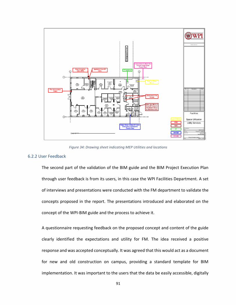
91
Figure 34: Drawing sheet indicating MEP Utilities and locations
6.2.2 User Feedback
The second part of the validation of the BIM guide and the BIM Project Execution Plan
through user feedback is from its users, in this case the WPI Facilities Department. A set
of interviews and presentations were conducted with the FM department to validate the
concepts proposed in the report. The presentations introduced and elaborated on the
concept of the WPI-BIM guide and the process to achieve it.
A questionnaire requesting feedback on the proposed concept and content of the guide
clearly identified the expectations and utility for FM. The idea received a positive
response and was accepted conceptually. It was agreed that this would act as a document
for new and old construction on campus, providing a standard template for BIM
implementation. It was important to the users that the data be easily accessible, digitally

92
on their mobile phones and tablets. It should have an easy interface and require minimum
training. Another key factor that was identified was that the BIM Guidelines document
would require to be updated periodically to be up-to-date and this wouldn’t be the last
and final version. This, in fact was just a beginning.
Table 3: Interview data tabulation
93
7 CONCLUSION AND FUTURE WORK
The objective of this research project was to conduct an extensive review of documented
approaches and guidelines for BIM uses developed by other universities and incorporate the
different experiences with the use of BIM at WPI to create a set of formal guidelines
exclusively for WPI for the efficient implementation of BIM in future design, construction,
renovation, facility, and space management of a facility.
The BIM guide for the WPI Facilities Department has been created and it is expected to
provide a systematic approach for the integration of BIM for existing and new buildings on
campus. Strategic planning in the use of BIM will help in assessing existing conditions, align
BIM goals and visions, and develop a path for implementation of BIM for operations. The
creation of this guide followed a rigorous methodology that included case studies, content
analysis and interviews. The case studies conducted provided a wide perspective in the sue
of BIM from different organizations of varying sizes and at various BIM implementation levels.
7.1 Benefits of the BIM Guide
The BIM guide for the FM department will benefit in the following ways:
Improved space management: By understanding the details of how space is used, facility
professionals can reduce vacancy and ultimately achieve major reductions in real estate
expenses. The room and area information in BIM models are the foundation for good space
management.
Streamline maintenance: The key challenge in developing a maintenance program is entering
the product and asset information required for preventive maintenance. The information

94
about building equipment stored in BIM models can eliminate months of effort to accurately
populate maintenance systems.
Efficient use of energy: BIM can also help facilitate the analysis and comparisons of various
energy alternatives to help facility managers dramatically reduce environmental impacts and
operating costs. By analyzing the costs and the savings of various facility improvements and
building system retrofits, facility managers gain a tool to optimize building performance over
the life of the building.
Economical retrofits and renovations: A BIM model provides an easier means of representing
three-dimensional aspects of the building. Better information about existing conditions
reduces the cost and complexity of building renovation and retrofit projects. This provides
more accurate and dependable information to contractors, change orders resulting from
“surprises” in as-built conditions can be greatly reduced.
Enhanced lifecycle management: Some building design professionals are embedding data on
life expectancy and replacement costs in BIM models, thereby helping an owner understand
benefits of investing in materials and systems that may cost more initially but have a better
payback over the life of the building. The lifecycle data is also very valuable for forecasting
ongoing capital improvement costs.
7.2 Recommendations
The validity of the proposed BIM Guide for WPI was established by applying its principles and
recommendations in to a pilot project and by collecting feedback from the potential users of
this document. An important element in this process is the BIM Project Execution Planning
95
process, in which there have been many concepts identified as recommendations for
successful future implementation. If these aspects are taken into consideration, it should
lead not only to a better BIM Project Execution Plan, but also a better implementation of BIM
throughout the life‐cycle of the project. These recommendations are discussed in detail
throughout the rest of this section.
Each project team needs a BIM Execution Plan. A project using the BIM Project
Execution Planning Procedure is successful when there is at least one representative
with a strong desire to develop the BIM Plan. Typically, from the owner organization
or a program/construction management role, these representatives take time to learn
the procedure and work to help compile final BIM Plan. They also market the value
and necessity of the process to the other project team members. It is important that
the representative on a project encourages the team to take the time to plan the
work, even if there is strong pressure to begin developing model content.
Owner involvement is critical throughout the entire process. By providing the
guidelines for model and information deliverables, the owner can emphasize the
importance of BIM implementation for reaching their desired end goals for the facility.
Owner involvement and enthusiasm regarding the process can encourage project
team members to seek the best processes that will benefit the entire project. Owners
should consider writing a BIM Project Execution Plan into their contract documents to
ensure that the document, planning, and project are completed to their
expectations.

96
It is essential that the project team fosters an open environment of sharing and
collaboration. The BIM Execution Planning Process requires organizations to provide
information regarding their standard practices, including information files. While
certain contract structures can lead to collaboration challenges, the goal of this
procedure is to have the team develop a BIM process containing deliverables that will
be beneficial to all members involved. To reach this agreement, the project team
needs to have open lines of communication. To be successful, the team members
must buy‐in to the process and be willing to share this intellectual content with other
team members.
The BIM Project Execution Planning Procedure can be adapted for multiple uses and
situations beyond the original scope of the project. Even if project teams take only
what they need from the procedure and do not complete the entire process, these
projects will still create comprehensive BIM Plans. Teams can revise the template
documents to fit their specific processes, without modifying any of the core steps of
the planning procedure. These teams then can eventually add other portions of the
procedure, which will further assist with their planning.
The BIM Project Execution Procedure can be adapted to different contracting
structures. Depending on the contract strategy, additional steps may be needed to
ensure project planning success. Developing an organizational BIM Project Execution
Plan before project inception can decrease project planning time. By performing
organizational level planning, the team can reduce the amount of time spent on each

97
step of the planning process and maintain a manageable planning scope by defining
their standard goals, uses, processes, and information exchanges.
There is great value in early planning. If planning does not take place early, extra time
may be needed to resolve inconsistencies at the later stages of the project. This often
results in more time and resources used than the original planning would have
needed.
The BIM Plan should be treated as a live document. When beginning the BIM Project
Execution Planning process, it is valuable to understand that the BIM Plan will be
constantly changing and updated. It is unrealistic to assume that the project team
will have all information necessary to completely develop a BIM Plan at the inception
of the project. It will take time to populate the information because additional and
new information must be incorporated as project team members are added.
Once an initial plan is developed, it must be reviewed regularly. A revision schedule
needs to set based on a frequency that the project team deems
appropriate. Throughout the lifecycle of the project, it is important to keep the initial
project goals in mind to ensure that the team is working towards their completion. If
there is any deviation, there should be a reassessment of or a reevaluation of the
original goals.
The appropriate resources must be made available to ensure planning success. It is
important to keep in mind that the level of effort needed for this process should not
be underestimated. Project teams must consider the time allocated for planning when
generating both the project schedule and project budget. Due to the learning curve
98
associated with this process, teams should overestimate the time it will take to
produce a BIM Project Execution Plan. The time associated with the learning curve
can be reduced by educating involved team members before delving into the process.
Without proper planning before the project specific meetings begin, many
unexpected issues may arise that could have been solved at an earlier time.
This procedure creates an opening for all BIM related discussions. Certain issues may
have been assumed or not even considered before the initial planning meeting. These
discussions, while maybe not pertaining directly to the BIM Execution Plan, may be
extremely important and necessary to allow for the entire project to run seamlessly.
The BIM Project Execution Planning Process will become more efficient once the
teams have gone through the process several times and have developed many of their
own planning resources.
The management and maintenance of a building can be positively affected by storing
the closeout documentation within the record BIM, thereby allowing the concepts of
Asset Management and Preventative Maintenance to be applied by the Department
of Facilities. The key to implementing the exchange of intelligent building information
throughout a project requires a contractual agreement by the Owner and
Construction Manager. This agreement must specify the components of the building;
content required for each element, and the accuracy of the data objects that make up
the record BIM.
The use of BIM in the design and post-construction phases is emerging from a new
technology into a developed standard of the industry. Implementing the proposed

99
BIM guide for the whole lifecycle of the project will be beneficial to the overall success
of the project. This guide would need to be updated periodically to stay up to date
with the different tool requirements (Revit, AutoCAD, Navisworks). Training users on
the guide is very significant for successful implementation of the guide. Another
important aspect would be to include BIM in contract document with the designer.
Periodically updating and maintaining the BIM guide to have an up-to-date document
in hand.
Through this work, owners can reap the benefits of implementing a reliable exchange and
storage of information process that not only assists during the design and construction of
a facility but also benefits in the long-term, during the lifecycle of the facility, making
campus planning and facility management a more efficient process.
100
Bibliography
American Institute of Architects, 2013, AIA Document G202™–2013, Project Building Information Modeling Protocol Form Best, R., Langston, C. & De-Valence, G., 2003. Workplace Strategies and Facilities Management, USA: Butterworth Heinemann BIM Dictionary [online] Available at: https://www.specifiedby.com/resources/bim-dictionary
BIM Terminology [online] Available at: http://www.mitbrand.com/advocacy/bim_language/
Building Information Modeling (BIM): A New Paradigm for Visual Interactive Modeling and
Simulation for Construction Projects [online] Available at: http://civil.neduet.edu.pk/ICCIDC-
I/Conference%20Proceedings/Papers/045.pdf
BIM Guidelines Inform Facilities Management Databases: A Case Study over Time, Karen Kensek [online] Available at: http://www.mdpi.com/2075-
5309/5/3/899/pdf
BIM Project execution planning guide, 2010 [online] Available at:
http://www.engr.psu.edu/ae/cic/bimex/downloads/guide/bim_pxp_guide-v2.0.pdf
BIM Implementation strategies [online] Available at:
http://web.stanford.edu/group/narratives/classes/08-
09/CEE215/ReferenceLibrary/National%20BIM%20Standard%20(NBIM)/bim_implement_strate
gies.pdf
BIM Planning guide for facility owners [online] Available at:
http://www.fm.virginia.edu/fpc/contractadmin/documents/bimplanningguide.pdf
BIM Planning Guide for Facilities Owners, June 2013 [online] Available at:
http://bim.psu.edu/resources/owner/bim_planning_guide_for_facility_owners-version_2.0.pdf
Brian Gilligan and John Kunz Center for Integrated Facility Engineering (CIFE), 2007- VDC Use in
2007: Significant Value, Dramatic Growth, and Apparent Business Opportunity
Clifford F. Hungu, 2013, Utilization of BIM from Early Design Stage to facilitate Efficient FM
Operations [online] Available at:
http://publications.lib.chalmers.se/records/fulltext/183268/183268.pdf
Doskocil, C., Vaitkunas. M., "Foisie Innovation Studio: The Role of BIM in Lifecycle Collaborative
Design", Major Qualifying Project, Worcester Polytechnic Institute, March 2017 (in progress)

101
East, E.W., 2007. Construction Operations Building Information Exchange (COBIE):
Requirements Definition and Pilot Implementation Standard.
Framework & Case Studies Comparing Implementations & Impacts of 3D/4D Modeling Across
Projects, Ju Gao & Martin Fischer [online] Available at:
http://cife.stanford.edu/sites/default/files/TR172.pdf
Fuller, S. 2010, Life-Cycle Cost Analysis (LCAA), National Institute of Building Sciences [online] Available at: http://www.wbdg.org/resources/lcca.php Gallaher, M.P. et al., 2004. Cost Analysis of Inadequate Interoperability in the U. S.Capital Facilities Industry Georgia Tech BIM Requirements & Guidelines for Architects, Engineers and Contractors, 2011 [online] Available at: http://www.facilities.gatech.edu/files/DC/2011_0815_GT_BIM_Requirements_v1.0.pdf Goedert, J.D. & Meadati, P., 2008. Integrating Construction Process Documentation into Building Information Modeling. journal of Construction Engineering and Management, (July), pp.509–516 Graham Kelly, Michael Serginson, & Steve Lockley, 2013, BIM for facilities management: A review and a
case study investigating the value and challenges, [online] Available at:
http://www.academia.edu/5144652/BIM_FOR_FACILITY_MANAGEMENT_A_REVIEW_AND_A_CASE_STU
DY_INVESTIGATING_THE_VALUE_AND_CHALLENGES
GSA BIM Guide for facility Management [online] Available at:
http://www.gsa.gov/largedocs/BIM_Guide_Series_Facility_Management.pdf
Handbook of BIM, Eastman, Teicholz, Sacks & Liston 2011 Indiana University BIM Guidelines & Standards for Architects, Engineers, and Contractors [online] Available at: http://www.indiana.edu/~uao/docs/standards/IU%20BIM%20Guidelines%20and%20Standards.pdf Karen Kensek, 2015, BIM Guidelines Inform Facilities Management Databases: A Case Study over Time Lee, G., Sacks, R., and Eastman, C. M. (2006). Specifying parametric building object behavior (BOB) for a building information modeling system. Automation in Construction Mehmet Yalcinkaya and David Arditi, Building Information Modeling and the Construction Management Body of Knowledge [online] Available at: https://wiki.aalto.fi/download/attachments/80938572/PLM_Conference_MY_Updated_20052013.pdf?version=1&modificationDate=1385329500000&api=v2

102
NBS International BIM Report 2016 [online] Available at:http://www.bauen-digital.ch/assets/Medienmitteilung/1603-NBS-International-BIM-Report.pdf Ning Gu and Kerry London, 2010, Understanding and facilitating BIM adoption in the AEC industry [online] Available at: http://www.sciencedirect.com/science/article/pii/S0926580510001317 Ning Gu, Vishal Singh and Xiangyu Wang, 2011, A theoretical framework of a BIM-based multi-disciplinary collaboration platform [online] Available at: http://www.sciencedirect.com/science/article/pii/S0926580510001408 National BIM Standard-United States, 2015 [online] Available at:
https://www.nationalbimstandard.org/files/NBIMS-US_FactSheet_2015.pdf
Pavan Meadati, BIM Extension into Later Stages of Project Life Cycle
http://citeseerx.ist.psu.edu/viewdoc/download?doi=10.1.1.543.2104&rep=rep1&type=pdf
Postsecondary Education Facilities Inventory and Classification Manual (FICM): 2006 Edition
[online] Available at: http://nces.ed.gov/pubs2006/2006160.pdf
Sergio O. Alvarez-Romero, 2014, Use of Building Information Modeling technology in the
integration of the handover process and facilities management (PhD thesis report, WPI)
SmartMarket Report, 2012 [online] Available at: http://bimforum.org/wp
content/uploads/2012/12/MHC-Business-Value-of-BIM-in-North-America-2007-2012-SMR.pdf
Susan Keenliside, 2015, Comparitive analysis of existing building information (BIM) guides
[online] Available at: https://open.library.ubc.ca/cIRcle/collections/52660/items/1.0076411
The Uses of BIM-Classifying and Selecting BIM Uses [online] Available at:
http://bim.psu.edu/uses/the_uses_of_bim.pdf
The Ohio State University- BIM Project Delivery Standards [online] Available at:
https://fod.osu.edu/bim/ohio-state_bim_pds.pdf
Trevor Bertin, Kelsey McMenamy, James Ricci and Peter Schembri, 2011, Enhancing Facilities
Management and Structural Design through Building Information Modeling [online] Available
at: https://web.wpi.edu/Pubs/E-project/Available/E-project-031511-
115720/unrestricted/MQP_Rec_1_Final_Report.pdf
University of Southern California- BIM guidelines [online] Available at:
http://facilities.usc.edu/uploads/documents/cas/BIMGuidelines_VS1_6_2012.pdf
Worcester Polytechnic Institute [online] https://www.wpi.edu/about

103
Worcester Polytechnic Institute Sustainability Tracking, Assessment & Rating System (STARS)
Report, 2015 [online] Available at:
https://www.sierraclub.org/sites/www.sierraclub.org/files/worcester-polytechnic-institute-
ma.pdf
Worcester Polytechnic Institute Acronym Dictionary [online] Available at:
http://wpi.collegeacronyms.org/buildings.html
Worcester Polytechnic Institute Standard Eight: Physical Resources [online] Available at:
https://web.wpi.edu/Images/CMS/Outcomes/standard08.pdf
104
Appendix A: Terminology A
As-Built Documents
As-built documents are the collection of paper drawings or electronic drawings that typically
reside in the contractor’s onsite trailer that contain mark-ups, annotations, and comments about
changes that have been made to the contract documents during the construction phase.
As-Built Model
Design Intent Models that have been updated throughout the construction process. These
changes and updates have been communicated from the Contractor to the Design Team through
the comments, annotations, and mark-ups from the As-Built Documents. These typically, but not
always, are discipline specific models.
B
BIM Execution Plan (BEP)
A plan that is created from the WPI BIM Execution Plan Template that is to be submitted thirty
days after contract award. The BEP helps to define roles and responsibilities within a project
team.
BIM Proficiency Matrix (BPM)
A matrix designed to measure the expertise of a firm as it relates to using a BIM process on
projects. It will be used as one of the many selection criteria during the selection process.
C
COBie - Construction Operations Building Information Exchange
105
COBie is a standard of information exchange that allows information to be captured during
design and construction in a format that can be used during the operations of a building once
completed.
Critical Path Modeling
Critical Path Modeling is a method of demonstrating Integrated Project Delivery, and tied to the
AIA E202 level of development approach. It sets a plan within the design team that accounts for
the activities of each discipline and how they interact with each other. It builds upon a critical
path method for those activities, and allows the project team to schedule a complete project.
D
Design Team
The Design Team is considered the Architect and all of the consultants that provide design
services for a project. These design services can be rendered at any time during the project.
DWF
DWF is a file type developed by Autodesk to be locked and non-editable file for drawing sheets
and model data. It can be used as a file transfer for estimating data, markups, and other third
party software. It can be a combination of 3D and 2D information within the same file.
DWG
DWG is a native AutoCAD file format. It is a widely-used file format for exchanging drawing
information and 3D information to different programs. While not a database file type, it still has
lots of uses for exchanging information.

106
E
EIM - Energy Information Model
EIM is a concept of producing a “light” and “lean” model that can be used for simulating the
building’s performance very early within the design process. The EIM is the process of modeling
only the exterior envelope, and the interior volumes to produce a model that energy modeling
software can use.
F
FICM - Post Secondary Facilities Inventory and Classification Manual
FICM is standard that describes practices for initiating, conducting, reporting, and maintaining an
institutional facilities inventory.
I
IPD - Integrated Project Delivery
IPD describes a contractual relationship between all members of the project team including the
Owner, Designers, Consultants, and Construction teams. It is a project delivery method that
integrates people, systems, business structure and practices into a process that collaboratively
harness the talents and insights of all participants to optimize project results, increase value to
the owner, reduce waste, and maximize efficiency through all phases of design, fabrication, and
construction.

107
IPD Methodology
IPD Methodology is a concept that uses methods from the IPD contracts, but does not have the
contracts in place. It idealizes the concepts of integration of all team members to try and
benefit the entire project.
IPP Methodology Plan
The IPP Methodology Plan is a declaration of how the project team will achieve the goals of an
IPP Methodology. The plan can have several components and is encouraged to be part of the
BEP. The completion of a Reverse Phase Schedule or Critical Path Modeling is two examples of
an IPD Methodology Plan.
L
LEED
The Leadership in Energy and Environmental Design (LEED) Green Building Rating System is a
suite of standards for environmentally sustainable construction. Based on a point system, a
building can achieve different ratings based on the performance of the design, construction, and
operation of the building.
N
NavisWorks
NavisWorks is software that allows for the viewing of multiple model formats. This ability to
“view” these files also allows NavisWorks to simulate the interaction between model files. That
includes interference reporting, time lining, and coordination.

108
NWC
An .NWC file is a NavisWorks Cache File that is used by NavisWorks to quickly read many other
file types. All linked files in NavisWorks have an .NWC file created automatically. In addition,
Revit will export directly to the very small file type of .NWC for quick access by NavisWorks.
NWD
A much larger file than the .NWC, the .NWD file shows snapshots in time of a NavisWorks file.
No linked files exist but all geometry is included.
NWF
The .NWF file is a native NavisWorks file that has all linked files, interferences/ collisions,
markups, animations, schedules, etc.
O
Open Architecture
Open Architecture is a concept of creating a framework that helps to describe a common set of
rules for how a project is created. This includes what types of software, the interoperability of
the information, and how the participants interact with each other. This is different from open
standards in that it promotes progress while not anchoring forward thinkers to a rigid standard.
P
Phases
The phases of a project can be describe in two different ways as the adoption of IPD
terminology starts to penetrate the BIM Execution Plan and the IPD Methodology Plan. Below is
a list of the traditional names followed by the IPD name.

109
Pre-Design/Conceptualization Phase
Schematic Design/Criteria Design Phase
Design Development/Detailed Design Phase
Construction Documents/Implementation Phase
Project Team
The Project Team is considered the combination of the Design Team, Contractor, and at times,
GT faculty; a complete team needed to make holistic project decisions and approvals.
R
Record Drawing
The production of Record Drawings is the capturing of the As-Built Document’s annotation,
comments, and mark-ups in a drawing format only. This does not typically include the updating
of any models.
Reverse Phase Scheduling
Reverse Phase Scheduling Is a method of demonstrating Integrated Project Delivery. It sets a
plan within the design team that accounts for the activities of each discipline and how they
interact with each other. It uses the completion date as a point to work backward from to
schedule all of the project’s activities.
RVT
An .RVT file is a Revit native file type. It is also the deliverable file format for all projects. This
includes all of the Design Team’s models.

110
Appendix B: Interview Data
B.1 Questionnaire for Interviews
1. Do we need a Guide?
2. What do you think of the Proposed Content of the presentation?
3. What am I missing?
4. Who would be the users of the BIM guide?
5. What are your expectations from a BIM guide?
6. According to you, how helpful is a BIM guide for FM department?
7. How extensive would you like the BIM execution plan for new construction?
8. How extensive would you like the BIM execution plan for an existing construction?
9. According to you, what BIM deliverables are you expecting for the campus?
10. Pilot projects could be buildings that have already been completed for the FM BIM
project.
11. What is your most preferred means to access the BIM data? (Secure data)
12. Who would have access to the final files?
13. Any additional inputs/comments/feedback for the guide?

111
B.2 Interview Feedback
B.2.1 Participant 1: Bill Spratt
Director of Facilities Operations, Worcester Polytechnic Institute
1. Do we need a Guide?
- I think a guild would be helpful to make sure our BIM models are consistent
building to building
2. What do you think of the Proposed Content of the presentation?
- So far so good.
3. What am I missing? It is a good general outline. It is missing specifics, but I am assuming
that is the next step.
4. Who would be the users of the BIM guide?
- New project architects, project managers, and facilities operations managers and
tradesmen.
5. What are your expectations from a BIM guide?
- That is sets the stage for how BIM will be defined on campus and also builds a
foundation for end users to understand the benefits of BIM and how they can
use it to enhance their work.
6. According to you, how helpful is a BIM guide for FM department?

112
- It is useful as long as it is clear to understand and we have the tools to actually
use a BIM system. It can’t be something that is done once and sits on a shelf
after.
7. How extensive would you like the BIM execution plan for new construction?
- It should be extensive for new construction. It is a onetime chance to get all the
data managed well.
8. How extensive would you like the BIM execution plan for an existing construction?
- It needs to be as complete as practical. Some older buildings will not have the
data needed to make it robust. So, we have to be able to gather as much data as
we can without having to dig too deep. All critical items should be on an existing
building model like shut offs, major equipment, and an accurate space model.
9. According to you, what BIM deliverables are you expecting for the campus?
- Accurate space representations of the buildings, all major building components
shown, shut off valves, life safety systems, and the ability to modify the space as
new projects change the building.
10. Pilot projects could be buildings that have already been completed for the FM BIM
project.
- We do have several buildings started. Piloting building that already have work
on them makes sense. Keep in mind we have yet to actually use the system as it
is intended. We need to go from theoretical ideas to a practical use.

113
11. What is your most preferred means to access the BIM data?
- (Secure data) An easy interface that does not take constant training and use to
be proficient at.
12. Who would have access to the final files?
- Anyone who is authorized to see them.

114
B.2.2 Participant 2: James Bedard
Director of Construction Services, Worcester Polytechnic Institute
1. Do we need a Guide?
- Yes – This material will be very helpful in a wide variety of areas in the Facilities
Management Disciplines
2. What do you think of the Proposed Content of the presentation?
- The presentation was well organized and clearly defined.
3. What am I missing?
- This is not something that you are missing but a slight correction. The house on
Regent Street is #15 not #25.
4. Who would be the users of the BIM guide?
- Project Managers
- Architects & Designers
- Engineers
- Tradesmen
5. What are your expectations from a BIM guide?
- An organized easy to access and use set of guidelines on the BIM Models.
6. According to you, how helpful is a BIM guide for FM department?

115
- This information could be very useful if it is easy to use, current, and accessible
by the people that need it.
7. How extensive would you like the BIM execution plan for new construction?
- This is the opportunity to work with the architects and get the information in the
format that we are looking for from the start. We need to make sure that we are
engaging you and you teams early in the process to ensure consistency. This is
our greatest opportunity to get MEP, structural, site, and all other building
systems.
8. How extensive would you like the BIM execution plan for an existing construction?
- This is the piece that is going to take some time but we should start with the
architectural as they can be the used for many applications in and out of
Facilities (space planning, lab analysis, ADA, etc.) and then move onto MEP which
would be valuable to the trades.
9. According to you, what BIM deliverables are you expecting for the campus?
- Accurately measure buildings models with consistent formatting.
10. Pilot projects could be buildings that have already been completed for the FM BIM
project.
11. What is your most preferred means to access the BIM data?
- Secure data
12. Who would have access to the final files?

116
- This is highly accurate and detailed information and distribution should be
controlled for security reasons, I would think that Campus Police, Facilities,
Space Planning, etc.

117
B.2.3 Participant 3: Liz Tomaszewski
Facilities Systems Manager, Assoc. Director of Sustainability, Worcester
Polytechnic Institute
1. Do we need a Guide?
- Yes!
2. What do you think of the Proposed Content of the presentation?
- Very good.
3. What am I missing?
- This guide will develop over time. Right now we are starting with the basics.
4. Who would be the users of the BIM guide?
- Tradesmen, managers, contractors
5. What are your expectations from a BIM guide?
- Consistency of information in a standard format that is accessible to all who
need it. Over time, I expect it to grow to include more aspects of building
attributes.
6. According to you, how helpful is a BIM guide for FM department?
- Huge.
7. How extensive would you like the BIM execution plan for new construction?
- We need to have a standard template that is mandatory for new construction
projects.

118
8. How extensive would you like the BIM execution plan for an existing construction?
- Extensive, but with room to add over time.
9. According to you, what BIM deliverables are you expecting for the campus?
- Basically a standard template with all attributes across all buildings. And room
to expand.
10. Pilot projects could be buildings that have already been completed for the FM BIM
project.
11. What is your most preferred means to access the BIM data?
- Secure data on a smart device
12. Who would have access to the final files?
- Specifically designated individuals, including tradesmen, management, and
contractors.
13. Any additional inputs/comments/feedback for the guide?
- Ensure that we can grow the guide with time. Simplicity and accessibility are
key. Standard formatting.

119
B.2.4 Paticipant 4: Nick Palumbo
Project Manager, Department of Facilities, Worcester Polytechnic Institute
1. Do we need a Guide?
- Yes
2. What do you think of the Proposed Content of the presentation?
- Satisfactory
3. What am I missing?
- Guidelines for updating the guide to stay current with future technologies and
standards; Training for new users; Re-Training for existing users looking to stay
current with the latest technologies and practices. Who will be responsible for
keeping the BIM models current?
4. Who would be the users of the BIM guide?
- Facilities Managers, Trade Workers, Environmental Health and Safety (EH&S)
Managers, Outside Vendors (Architects, Consultants, Construction Managers,
Subcontractors), Campus Police.
5. What are your expectations from a BIM guide?
6. According to you, how helpful is a BIM guide for FM department?
- With a large number of users, a standardized set of BIM guidelines will be
essential
7. How extensive would you like the BIM execution plan for new construction?

120
- I think this depends on the specific project in question. Perhaps there could be a
baseline template that would be modified to meet the needs of each specific
project based on feedback from a representative group on users during the
planning phase of the project.
8. How extensive would you like the BIM execution plan for an existing construction?
- See above.
9. According to you, what BIM deliverables are you expecting for the campus?
- Searchable database of building information (approved product submittals, as-
builts, warranties, functional testing data, Cx reports, training documents and
videos, maintenance info); The same information also embedded in the visual 3D
models; Accurate coordinated 3D Models with exposed and in-wall MEP routing,
valve tags, cleanouts, detailed building construction. Progress photos. Software
and information available on handheld devices (iPads and iPhones).
10. Pilot projects could be buildings that have already been completed for the FM BIM
project.
11. What is your most preferred means to access the BIM data?
- Secure data directly from the secure campus network servers.
12. Who would have access to the final files?
- See #4.
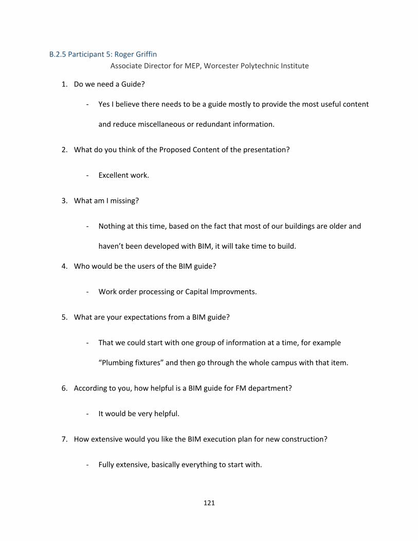
121
B.2.5 Participant 5: Roger Griffin
Associate Director for MEP, Worcester Polytechnic Institute
1. Do we need a Guide?
- Yes I believe there needs to be a guide mostly to provide the most useful content
and reduce miscellaneous or redundant information.
2. What do you think of the Proposed Content of the presentation?
- Excellent work.
3. What am I missing?
- Nothing at this time, based on the fact that most of our buildings are older and
haven’t been developed with BIM, it will take time to build.
4. Who would be the users of the BIM guide?
- Work order processing or Capital Improvments.
5. What are your expectations from a BIM guide?
- That we could start with one group of information at a time, for example
“Plumbing fixtures” and then go through the whole campus with that item.
6. According to you, how helpful is a BIM guide for FM department?
- It would be very helpful.
7. How extensive would you like the BIM execution plan for new construction?
- Fully extensive, basically everything to start with.
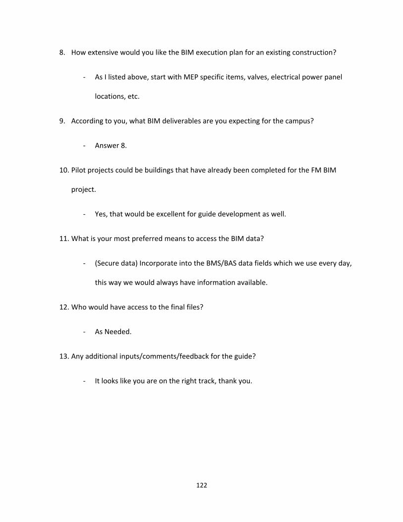
122
8. How extensive would you like the BIM execution plan for an existing construction?
- As I listed above, start with MEP specific items, valves, electrical power panel
locations, etc.
9. According to you, what BIM deliverables are you expecting for the campus?
- Answer 8.
10. Pilot projects could be buildings that have already been completed for the FM BIM
project.
- Yes, that would be excellent for guide development as well.
11. What is your most preferred means to access the BIM data?
- (Secure data) Incorporate into the BMS/BAS data fields which we use every day,
this way we would always have information available.
12. Who would have access to the final files?
- As Needed.
13. Any additional inputs/comments/feedback for the guide?
- It looks like you are on the right track, thank you.

123
B.2.6 Participant 6: Theresa Mailloux
Facilities Operations Coordinator, Worcester Polytechnic Institute
1. Do we need a Guide?
- Yes.
2. What do you think of the Proposed Content of the presentation?
- Great start.
3. What am I missing?
- I think with a ‘work in progress’ we may not know this answer until we are
looking for it.
4. Who would be the users of the BIM guide?
- Trades, Customer service, Project manager.
5. What are your expectations from a BIM guide?
- Must be easy to use and navigate, must be quick to pull up and show
information requested.
6. According to you, how helpful is a BIM guide for FM department?
- Could be very valuable in day to day operations.
7. How extensive would you like the BIM execution plan for new construction?
- As simple and broad as possible.
8. How extensive would you like the BIM execution plan for an existing construction?
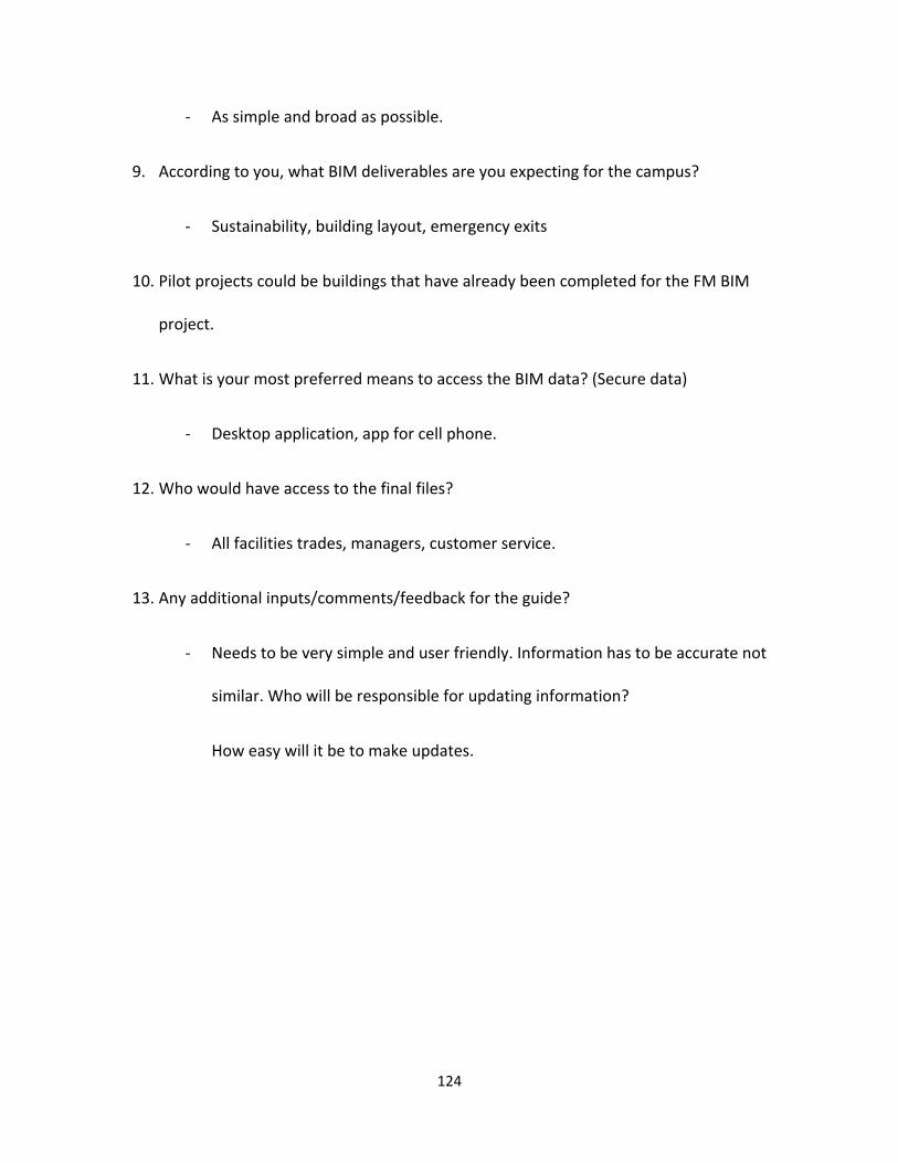
124
- As simple and broad as possible.
9. According to you, what BIM deliverables are you expecting for the campus?
- Sustainability, building layout, emergency exits
10. Pilot projects could be buildings that have already been completed for the FM BIM
project.
11. What is your most preferred means to access the BIM data? (Secure data)
- Desktop application, app for cell phone.
12. Who would have access to the final files?
- All facilities trades, managers, customer service.
13. Any additional inputs/comments/feedback for the guide?
- Needs to be very simple and user friendly. Information has to be accurate not
similar. Who will be responsible for updating information?
How easy will it be to make updates.

125
Appendix C: Worcester Polytechnic Institute BIM Guide
[THIS SPACE HAS BEEN INTENTIONALLY LEFT BLANK]

B U I L D I N G I N F O R M A T I O N M O D E L I N G
B I M GUIDE FOR CAMPUS PLANNING AND FACILITIES MANAGEMENT
[SOURCE: WPI.EDU]
STANDARDS, STRATEGIES, AND BEST PRACTICES VERSION 1.0 JANUARY 2017
PURVASHRI V. PADHYE
1
|BIM GUIDELINES
E x e c u t i v e S u m m a r y
The Building Information Modelling guide (BIM) is developed to support project teams by
leading them through a systematic process for BIM. The Architectural, Engineering,
Construction, and Operations (AECO) industry emphasizes the need for facility owners to
implement BIM throughout the lifecycle of the facility so that information can be derived
during a project that will add value to the business operations. Therefore, this BIM guide is
developed to assist facility owners to develop strategies, implementation, and procurement
plans for integrating BIM in the organization.
The BIM guide focuses on streamlining the planning and implementation of BIM within a
facility or project. The tools and processes can be project specific and can vary with a focus on
facility operations after complete.
This Guide presents a structured approach to effectively plan the integration of BIM within
WPI. Three planning procedures are presented:
STRATEGIC PLANNING: To assess existing conditions on campus, align BIM goals and
objectives with desired BIM uses and develop a transition plan for BIM implementation.
IMPLEMENTATION PLANNING: To develop the detailed implementation plan within the
operations of the organization.
PROCUREMENT PLANNING to identify key issues to consider when creating BIM project
requirements.
2
|BIM GUIDELINES
A d v i s o r y M e m b e r s
GUILLERMO F. SALAZAR, Associate Professor, Civil & Environmental Engineering
ALFREDO DIMAURO, Assistant Vice President of Facilities
BILL SPRATT, Director of Facilities Operations
ROGER GRIFFIN, Associate Director for MEP
BILL GRUDZINSKI, Chief Engineer
THERESA MAILLOUX, Facilities Operations Coordinator
TERRENCE PELLERIN, Associate Director of Buildings and Events
JIM BEDARD, Director of Construction Services
NICK PALUMBO, Project Manager
DANIEL SARACHICK, Director of Environmental Health and Safety
LIZ TOMASZEWSKI, Facilities Systems Manager, Associate Director of Sustainability

3
|BIM GUIDELINES
A c k n o w l e d g e m e n t s
I would like to express my deepest appreciation to all those who encouraged me and helped me
complete this BIM guide.
A special gratitude to my supervisor, Professor Guillermo Salazar whose guidance, contribution
and encouragement helped me to coordinate and successfully complete the following guide.
I would like to acknowledge with much appreciation the crucial role of Liz Tomaszewski, for her
stimulating support and suggestions which helped to form the basis for this research.
I want to thank everyone at the Facilities Department for their valuable inputs and time to help
formulate the research, especially Jim Bedard, Alfred Di Mauro, Bill Spratt, Roger Griffin, Theresa
Mailloux and Nick Palumbo.
A big thank you to Hannah Poirier for helping with coordinating, organizing meetings and
presentations with the Facilities Management department.
I would like to express my gratitude towards my parents and members of my family for their
support and encouragement towards the completion of this guide.

4
|BIM GUIDELINES
T a b l e o f C o n t e n t s
E x e c u t i v e S u m m a r y ........................................................................................................................ 1
A d v i s o r y M e m b e r s .......................................................................................................................... 2
1 INTRODUCTION .......................................................................................................................................... 7
1.1 What is Building Information Modelling (BIM)? ................................................................................. 7
1.2 The value of BIM for Facility Owners .................................................................................................. 7
1.3 How to Use this Guide ........................................................................................................................ 8
2 RENOVATIONS AND SPACE CHANGE PROJECTS REQUIREMENTS ........................................................... 10
2.1 Deliverables for Renovations and space change projects ................................................................ 10
2.1.1 Design phase .............................................................................................................................. 10
2.1.2 Construction phase .................................................................................................................... 10
2.1.3 Completion phase ...................................................................................................................... 11
3 NEW CONSTRCUTION PROJECTS REQUIREMENTS................................................................................... 12
3.1 Schematic design phase .................................................................................................................... 13
3.1.1 Model contents .......................................................................................................................... 13
3.1.2 Level of Detail ............................................................................................................................ 14
3.1.3 Design program and space validation ........................................................................................ 14
3.1.3 Design data documentation ....................................................................................................... 14
3.1.4 Initial conflict report and clash detection .................................................................................. 15
3.2 Design development phase ............................................................................................................... 15
3.2.1 Architectural .............................................................................................................................. 15
3.3 Construction documents phase ........................................................................................................ 17
3.4 Bidding phase .................................................................................................................................... 17
3.5 Construction phase ........................................................................................................................... 18
3.6 Project Closeout phase ..................................................................................................................... 18
3.6.1 Design team as-builts ................................................................................................................. 18
3.6.2 Contractors record documents .................................................................................................. 19
3.6.3 Operations and Maintenance (O&M) manuals.......................................................................... 19
4 CAD DRAWING PRODUCTION .............................................................................................................. 21
4.1 File format at setup ........................................................................................................................... 21

5
|BIM GUIDELINES
4.1.1 Electronic file format ................................................................................................................. 21
4.1.2 Scales, Units, and Tolerances ..................................................................................................... 21
4.1.3 Fonts and Text Styles ................................................................................................................. 21
4.2 Title Blocks ........................................................................................................................................ 22
4.2.1 Required Title Block Information ............................................................................................... 22
4.2.2 Required Sheet Information ...................................................................................................... 22
5 REVIT FILE PRODUCTION .......................................................................................................................... 24
5.1 File format at setup ........................................................................................................................... 24
5.1.1 Required Drawing Information .................................................................................................. 24
5.2 Translating CAD files to DWG format................................................................................................ 26
5.2.1 Translating from other CAD software ........................................................................................ 26
5.2.2 Translating from BIM software .................................................................................................. 26
5.2.3 DWG File Translation Testing ..................................................................................................... 26
6 BIM DELIVERABLES ................................................................................................................................... 27
6.1 BIM Execution Plan ........................................................................................................................... 27
6.2 Model information and level of details: ........................................................................................... 28
6.2.1 Architectural detailing................................................................................................................ 28
6.3 BIM Models and Deliverables ........................................................................................................... 30
6.3.1 Use of Revit and NavisWorks ..................................................................................................... 30
7 ARCHIVAL PRINT FILES AND FORMATS .................................................................................................... 31
7.1 PDF File Creation ............................................................................................................................... 31
8 INFRASTRUCTURE NEEDS ......................................................................................................................... 32
9 EDUCATION AND TRAINING ..................................................................................................................... 34
9.1 Education .......................................................................................................................................... 34
9.2 Training ............................................................................................................................................. 34
10 PILOT PROJECT SAMPLE ......................................................................................................................... 36
10.1 Project 1: Project Center ................................................................................................................. 36
B i b l i o g r a p h y ...................................................................................................................................... 43
T e r m i n o l o g y ....................................................................................................................................... 44

6
|BIM GUIDELINES
L i s t o f F i g u r e s
Figure 1: Deliverable and Milestone schedule ............................................................................................ 12
Figure 2: Project Center: Drawing sheet indicating Floor Finishes ............................................................. 36
Figure 3: Project Center: Drawing sheet indicating Ceiling Finishes........................................................... 37
Figure 4: Project Center: Drawing sheet indicating Architectural detailing ............................................... 38
Figure 5: Project Center: Drawing sheet indicating Space Use per FICM codes ......................................... 39
Figure 6: Project Center: Drawing sheet indicating Space Use (door tags) ................................................ 40
Figure 7: Project Center: Drawing sheet indicating Space Utilization and room capacities ....................... 41
Figure 8: Project Center: Drawing sheet indicating MEP Utilities and locations ........................................ 42

7
|BIM GUIDELINES
1 INTRODUCTION This section of the guide provides an overview of Building Information Modelling (BIM)
along with other important aspects of BIM that will assist with the usage of the guide.
1.1 What is Building Information Modelling (BIM)?
The U.S. National Building Information Modeling Standard (NBIMS-US) states that
Building Information Modeling (BIM) “is a digital representation of physical and functional
characteristics of a facility. As such, it serves as a shared knowledge resource for
information about a facility, forming a reliable basis for decisions during its life cycle from
inception onward.”
It is a process of creating an electronic model of a facility for visualization, engineering
analysis, conflict analysis, code criteria checking, cost engineering, as-built product,
budgeting, and many other purposes. The model serves as a knowledge rich resource for
all project participants that helps in information management and a collaborative
process.
1.2 The value of BIM for Facility Owners
Implementation of BIM is gaining momentum within the Architectural, Engineering,
Construction, and Operations (AECO) Industry. Project teams are now moving from
standard 2D to 3D models that can be easily modified, Maintained, and coordinated
throughout the lifecycle of a facility.
The 2012 BIM Smart Market Report states that the industry-wide adoption of BIM
surged from 28% in 2008 to 71% in 2012 with architects, engineers, contractors, and
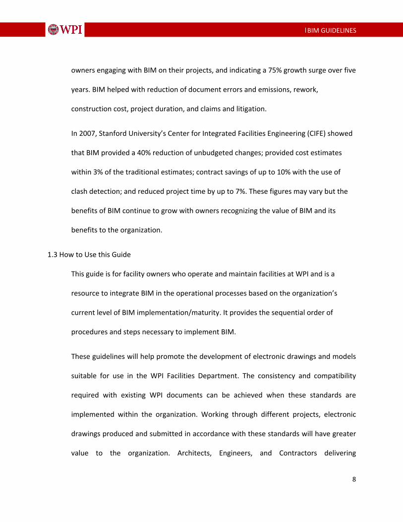
8
|BIM GUIDELINES
owners engaging with BIM on their projects, and indicating a 75% growth surge over five
years. BIM helped with reduction of document errors and emissions, rework,
construction cost, project duration, and claims and litigation.
In 2007, Stanford University’s Center for Integrated Facilities Engineering (CIFE) showed
that BIM provided a 40% reduction of unbudgeted changes; provided cost estimates
within 3% of the traditional estimates; contract savings of up to 10% with the use of
clash detection; and reduced project time by up to 7%. These figures may vary but the
benefits of BIM continue to grow with owners recognizing the value of BIM and its
benefits to the organization.
1.3 How to Use this Guide
This guide is for facility owners who operate and maintain facilities at WPI and is a
resource to integrate BIM in the operational processes based on the organization’s
current level of BIM implementation/maturity. It provides the sequential order of
procedures and steps necessary to implement BIM.
These guidelines will help promote the development of electronic drawings and models
suitable for use in the WPI Facilities Department. The consistency and compatibility
required with existing WPI documents can be achieved when these standards are
implemented within the organization. Working through different projects, electronic
drawings produced and submitted in accordance with these standards will have greater
value to the organization. Architects, Engineers, and Contractors delivering

9
|BIM GUIDELINES
documentation to WPI must ensure these standards are reviewed, understood, and
followed by those people responsible for preparing electronic drawings and models.
The following sections contain essential criteria for developing electronic drawings and
models for the use in the WPI CAD and BIM environment.
10
|BIM GUIDELINES
2 RENOVATIONS AND SPACE CHANGE PROJECTS REQUIREMENTS
When an existing building at WPI is undergoing a renovation or space change project, it
is the responsibility of the designer to submit a complete set of construction documents
(CDs) to WPI prior to the beginning of construction. During construction, it is the
responsibility of the contractors to submit complete As-Built documentation to the
project team as described in their contracts (typically in both electronic and hardcopy
formats) The designers are responsible for submitting the record documents to WPI based
on the As-Built documentation. Construction Documents and Record Documents
submitted to WPI will need to adhere to the criteria outlined in this document.
2.1 Deliverables for Renovations and space change projects
The following documentation shall be submitted to WPI at different stages through the
project.
2.1.1 Design phase
When a project is nearing the end of a design phase, the designer shall submit a complete
set of Design documents (DD) in electronic and hard copy format to WPI. The documents
should be archived to be used in the future.
2.1.2 Construction phase
When a project enters the construction phase, the designer shall submit a complete set
of 100% Construction Documents (CD) in electronic and hard copy format to WPI. These
documents will be archived as a record of the project.

11
|BIM GUIDELINES
2.1.3 Completion phase
When the project has been completed, it is the responsibility of the contractors to submit
a complete set of As-Built (AB) Documents to the project team as mentioned in their
contracts (typically in electronic and hardcopy formats). Designers are required to submit
the Record Drawings based on the As-Builts and need to comply by the format
requirements outlined in this document. Any other additional information if submitted
must meet the requirements outlined in WPI Project Archiving Guidelines.

12
|BIM GUIDELINES
3 NEW CONSTRCUTION PROJECTS REQUIREMENTS
Figure 1: Deliverable and Milestone schedule

13
|BIM GUIDELINES
3.1 Schematic design phase
The Design Team may use any method to begin the design process but shall be using a B
IM authored model(s) by completion of this phase. All information needed to describe t
he schematic design shall be included in and derived from these models. Deliverables ar
e required as stated in the deliverable and milestones schedule in figure 1 .
3.1.1 Model contents
Civil Surface and Utilities
Detailed requirements of what is to be included in surveying deliverables is managed by
WPI staff in consultation with the Design Team on a project by project basis. Surveys
shall be provided in electronic format and include 3D topographic information indicating
paving, retaining walls and civil utilities. The civil engineer will provide control points to
use as a reference to develop project gridlines and location. The design team shall model
all existing conditions and include the level of information as determined by the project
needs. The BIM Execution Plan (BEP) will define the scope and details of the model.
Architectural
The model geometry shall include:
The building footprint definition and all exterior walls.
All interior wall definitions with all rooms modeled individually.
All fenestrations.
All doors.

14
|BIM GUIDELINES
All overhangs, sun shades and roof elements.
All floors, with a separate floor finish model element per room.
3.1.2 Level of Detail
All elements shall be modeled to the standards set forth by the BEP. Clearances and
access zones should be modeled on separate layers. The model should include area,
height, volume, location, and orientation.
3.1.3 Design program and space validation
The design team shall use the BIM authoring software and other analysis tools to compare
and validate the program requirements with the actual design solution
The following shall be developed automatically from the Building Information Model:
a. Assignable areas and Non‐assignable areas measured to inside face of wall objects
and designated boundaries of areas.
b. Gross Area measured to the outside face of wall objects.
3.1.3 Design data documentation
The design team shall submit all the design data to WPI in an Excel spread sheet format
or a spreadsheet format in compliance with the most current version of COBie. The choice
for either would be project specific.
15
|BIM GUIDELINES
3.1.4 Initial conflict report and clash detection
The design team BIM facilitator should integrate all the models into a single consolidated
model and run a clash detection test for this phase of the project. The facilitator could
also perform a walkthrough of the model from various perspectives and cross sections to
detect any constructability issues. The issues should be addressed on a floor by floor basis.
The intention is to have an error and collision free model at the earliest phases of
construction.
3.2 Design development phase
3.2.1 Architectural
The design team is required to model the architectural elements to a level that defines the
design intent and accurately represents the design solution.
The detail and responsibility to fulfill these modeling requirements should be addressed fully wi
thin the BIM Execution Plan.
Architectural Site Plan (also see Civil Engineering section below). Paving, grades, sidewalks, cur
bs, gutters, site amenities and other elements typically included on enlarged scale site drawings
in vicinity of building.
Existing conditions to the extent required.
New interior and exterior walls to their correct and accurate height including but not lim
ited to: Doors, windows, openings
All finishes need to be included within the wall type regardless of the thickness of the

16
|BIM GUIDELINES
finish.
Interior and exterior soffits, overhangs, sun control elements
Parapets, screening elements
Architectural precast
Floor, ceiling, and roof systems including but not limited to:
Appropriate structural items listed below if not provided by the Structural Engineer and
integrated into the architectural model for coordination and document generation.
Insulation, ceiling systems, and floor are to be included.
Roof, floor, and ceiling slopes, if needed, shall be modeled.
Soffits, openings, and accessories shall also be modeled.
Elevators, stairs, ramps including railing systems.
Casework, shelving, and other interior architectural elements.
Furnishings, fixtures, and equipment if not provided by others and integrated into the ar
chitectural model for coordination and document generation.
Furniture (Fixed and Loose).
Furniture Systems.
Specialty equipment (food service, medical, etc.).
Model mechanical, electrical, and plumbing items that require architectural space (toilet
s/sinks/etc),
require color/finish selection (louvers, diffusers, etc.) or affect 3D visualization (lighting f
ixtures)

17
|BIM GUIDELINES
unless provided by Engineers.
Clearance zones for access, door swings, service space requirements, gauge reading, and
other
operational clearance must be modeled as part of all equipment and checked for conflic
ts with other
elements. These clearance zones should be modeled as translucent solids on a separate
layer.
3.3 Construction documents phase
The Design Team should continue development of the models created in the Preliminary
Design Phase. Maintain links within the respective models to enable automatic
generation of all plans, sections, elevations, custom details, schedules, and data export/
import, analysis as well as 3D views. All information needed to describe the construction
documents shall be graphically or alphanumerically included in and derived from these
models only. Specifications are not required to be linked within the models, but will be
accepted if coordinated.
3.4 Bidding phase
The Design Team shall update the models with all addendum, accepted alternates and/or
value enhancement proposals. Contractors who are bidding on WPI projects are required
to review the BIM Execution Plan and WPI Building Information Modeling (BIM)
Guidelines. Contractor will follow the guidelines and requirements as set forth by the BIM
18
|BIM GUIDELINES
Execution Plan. Thirty days after the project is awarded for construction, the Design Team
shall submit to the University Office one set of the Construction Document Deliverables.
This deliverable shall consist of CAD files representing every sheet in the Bid Documents.
3.5 Construction phase
The Design Team is expected to continuously maintain and update the design intent
model(s) with changes made from official Construction Change Directives and as-built
mark-ups maintained on site by the Contractor(s) during construction site.
Milestone Deliverables in the construction phase (contractor)
BEP Review
Discipline Specific Coordination Models
Clash Detection
Shop Drawing Models
Fabrication Models
As-Built Markups (2D/3D DWF and DWG formats)
Scheduling and Phasing Models
3.6 Project Closeout phase
3.6.1 Design team as-builts
The Design Team shall ensure that their models are updated per the contractor recorded
changes (Record Documents). Republish record documents in paper and .PDF formats.
They will also have to submit full model(s) with all needed objects and reference

19
|BIM GUIDELINES
drawings, in required deliverable formats. The design team shall update their respective
models with contractor-recorded changes. DWG files shall be provided for all drawing
sheets in addition to DWG (bind all xrefs) for the BIM models. All BIM files shall be
provided in RVT and NWD.
3.6.2 Contractors record documents
The contractor shall submit one set of scanned field set drawings (Record Documents) in
.PDF and .DWG format due 30 days after substantial completion. DWG files shall be
provided for all drawing sheets in addition to DWG (bind all xrefs) for the BIM models. All
BIM files shall be provided in RVT and NWD. All fields are to be filled out for all documents
(sheets) and shall be provided at Close-out.
3.6.3 Operations and Maintenance (O&M) manuals
The contractor shall submit the following information to WPI - two paper copies in binders
and a single PDF of the O&M Manuals along with the Construction Operations Building
Information Exchange (COBie) current format:
The make, model, and serial number of each piece of installed equipment
The location of any equipment installed in the building
Manufacturer’s documents including cut sheets, installation instructions, and
recommend maintenance tasks, testing or other reports.
An electronic format of the O&M manuals shall be submitted along with the paper copies,
the format shall be color PDF and native Excel (.XLS) files. This will be due 30 days after

20
|BIM GUIDELINES
substantial completion. O&M manual documents should be independently linked to
components and systems within the COBie deliverable.

21
|BIM GUIDELINES
4 CAD DRAWING PRODUCTION
The following section will give information on the drawings produced using CAD and
standard for submission of the drawings.
4.1 File format at setup
4.1.1 Electronic file format
Construction and Record Document project drawings must be submitted in the file
formats listed below, other formats are not acceptable without the prior consent of
WPI’s Facility Information Systems (FIS).
AutoCAD 2008 or higher – DWG format only.
Adobe PDF version 6.0 or higher.
TIF 6.0
4.1.2 Scales, Units, and Tolerances
All CAD drawing models shall be drafted at full scale in architectural units, such that one
drawing unit equals one inch.
4.1.3 Fonts and Text Styles
Drawings created using non-standard AutoCAD fonts, line types, and hatch patterns can
result in content discrepancies in the delivered drawing set. To ensure the integrity of
the drawing set and minimize potential problems:
• Only native AutoCAD fonts, line types and hatch patterns are to be used. These are
standard support features installed as part of a standard AutoCAD installation.

22
|BIM GUIDELINES
• Custom fonts, line types and hatch patterns, including those provided by 3rd party
software, shall not be used.
• Only these TrueType fonts shall be used: Arial, Courier New, Times New Roman.
4.2 Title Blocks
Each CAD file submitted to WPI shall have only one title block. In paper space, the title
block shall be placed with its lower left hand corner point inserted at a coordinate
location of (0,0,0). Depending on the purpose of the drawing or facility documentation,
the drawing’s title block shall contain certain essential information that WPI needs to
store and retrieve each drawing in its library.
4.2.1 Required Title Block Information
• Original issue date - this date should not change once the drawing has been issued
• Sheet number
• Title - description of drawing and location information. Location information should
include all building, floor, and room numbers as applicable.
• Revision history - as applicable
• Drawing phase - drawings submitted as As-Builts should clearly be marked
• WPI Project number - if applicable
• A/E/C – Consultant responsible for producing the drawings should be clearly
identified
4.2.2 Required Sheet Information
• Drawing title - indicating the drawing content, e.g. floor plan, section, detail, etc.

23
|BIM GUIDELINES
• Sheet identification – must follow the Sheet Naming Convention
• Date of drawing - date of final revision of the record drawing
• Drawing Scale - representing the intended plot scale of the drawing with title block
• North Arrow showing orientation of drawing (when applicable)
24
|BIM GUIDELINES
5 REVIT FILE PRODUCTION
5.1 File format at setup
All drawings created will be assigned a drawing file name and number. Since we are
working on number of buildings on the WPI campus it is most likely to have the same
drawing name. This could be confusing while browsing through drawings and thus these
have been categorized job wise.
Sheets will be organized in the following sequence:
PC-A-100-Plan views-2015.06.17 which represents the following
Building Name-Discipline name-Sheet number-Sheet description-Date when it was
created
5.1.1 Required Drawing Information
In the drawing number, building name will be indicated first to immediately point out
which project are we referring to followed by the discipline name followed by the
drawing number, the description, and the date it was created on.
Sheets will be numbered consecutively within a series from 00 to 99.
Sheets in a bound set should be organized in the following sequence:
A – Architectural
AL – Architectural Large scale
AD - Architectural Details
D - Rooms by department
25
|BIM GUIDELINES
I – Interiors
US – Utility Services
FICM - Facilities Inventory and Classification Manual
SU – Space Utilization
Drawing numbering sequence is as follows:
100 series: Architectural plans, Floor finishes layout, Ceiling finishes layout
200 series: Elevations and sections of the building
300 series: Large scale plans, elevations, sections
400 series: Details
500 series: Rooms by department
600 series: Interior area, detailing and door tags
700 series: Utility Services- Mechanical, Electrical and Plumbing indicated
800 series: Space use FICM
900 series: Space Utilization room capacity
The work completed on existing five buildings would be indicated as follows:
PC – Project center
WB – Washburn shops
SL – Salisbury Labs
IH – Institute Halls
RH – Riley Halls

26
|BIM GUIDELINES
5.2 Translating CAD files to DWG format
5.2.1 Translating from other CAD software
WPI understands that many of its vendors do not use the same version of design software to
produce plans for their projects. However, WPI requires that service providers who work with
other file formats submit DWG formatted CAD files upon project closeout that are fully
compliant with all the standards outlined herein, and which have no significant loss of drawing
entities or project data that can result from standard CAD file translation procedures.
5.2.2 Translating from BIM software
Projects using Building Information Modeling (BIM) software like Revit are still required to
produce DWG and PDF formats for the projects. The use of the National CAD Standard will help
facilitate the production of properly formed DWG files.
5.2.3 DWG File Translation Testing
For firms translating their native CAD file format into DWG format concerned about delivering
error-free CAD files to WPI upon project closeout, it is strongly recommended that thorough file
translation testing be conducted before the drawing development phase of the project. This
will assure early detection of file conversion issues, if any, and allow for corrective measures to
be taken before the project closeout period.

27
|BIM GUIDELINES
6 BIM DELIVERABLES
6.1 BIM Execution Plan
Projects using BIM are required to use the WPI BIM Execution Plan to document
modeling practices. This document declares what is being modeled, the accuracy of the
models, the intent of the models, and how project teams work within the models.
Software platforms and procedures are also outlined and agreed upon in this document.
The intent of these requirements is to create a prescriptive framework with which BIM
enabled teams will coordinate with WPI and other applicable groups. This document will
allow all stakeholders to weigh the importance of each requirement on a per-project
basis. Through this collaborative effort, a final project-based set of requirements and
corresponding BIM Execution Plan will be issued based on what level of BIM proficiency
necessary for a given project.
WPI requires that all design and construction deliverables for projects be created and
derived from building information models, and expects that data associated with the
installed components of these facilities be reconciled and validated with the construction
deliverables. It is WPI’s intention to reuse these models and data for facility lifecycle
management.
Building information models shall be provided throughout the design, construction, and
close out phases along with an emphasis on corresponding building data collection to be
gathered using the Construction Operations Building Information Exchange (COBie) to
28
|BIM GUIDELINES
capture and record close out data. COBie is an information exchange used to collect
building data in spreadsheets that can be tied to BIMs for efficiency and are used to assign
building components unique naming conventions outlined later in the document, so that
information can be consumed and validated through WPI’s data management processes.
Unique IDs, assigned in the BIM tools, shall be maintained to support data in workflows
that can then be used throughout the design, construction, and building handover
process.
Portions of this life-cycle oriented data format will be required for a variety of different
building information deliverables that will replace paper deliverables. The deliverables for
the Close-out in COBie format include, but are not limited to:
• Verification of the design solution against the Program for Design
• Scheduled building equipment/component lists
• Construction submittal register requirements
• Identification of installed equipment and all tagger building products
• Close-out deliverables
6.2 Model information and level of details:
6.2.1 Architectural detailing
Model the architectural elements to a level that defines the design intent and accurately
represents the design solution. The detail and responsibility to fulfill these modeling
requirements should be addressed fully within the BIM Execution Plan.
29
|BIM GUIDELINES
Architectural Site Plan (also see Civil Engineering section below). Paving, grades,
sidewalks, curbs, gutters, site amenities and other elements typically included on
enlarged scale site drawings in vicinity of building.
Existing conditions to the extent required.
New interior and exterior walls to their correct and accurate height including but not
limited to: Doors, windows, openings
All finishes need to be included within the wall type regardless of the thickness of the finish
Interior and exterior soffits, overhangs, sun control elements, parapets, screening elements
architectural precast elements.
Floor, ceiling, and roof systems including but not limited to:
Appropriate structural items listed below if not provided by the Structural Engineer and
integrated into the architectural model for coordination and document generation.
Insulation, ceiling systems, and floor are to be included.
Roof, floor, and ceiling slopes, if needed, shall be modeled.
Soffits, openings, and accessories shall also be modeled.
Elevators, stairs, ramps including railing systems.
Casework, shelving, and other interior architectural elements.
Furnishings, fixtures, and equipment if not provided by others and integrated into the
architectural model for coordination and document generation.
Furniture (Fixed and Loose).
Furniture Systems.

30
|BIM GUIDELINES
Specialty equipment (food service, medical, etc.).
Model mechanical, electrical, and plumbing items that require architectural space
(toilets/sinks/etc.), require color/finish selection (louvers, diffusers, etc.) or affect 3D
visualization (lighting fixtures) unless provided by Engineers.
Clearance zones for access, door swings, service space requirements, gauge reading, and
other operational clearance must be modeled as part of all equipment and checked for
conflicts with other elements.
6.3 BIM Models and Deliverables
Models submitted to WPI as a deliverable must meet the requirements of the agreed upon WPI
BIM Execution Plan. Internally, WPI has standardized its BIM environment on existing work done
on BIM and models created for projects are expected to work within WPI’s CAD/BIM
environment.
6.3.1 Use of Revit and NavisWorks
It is recommended that models are created in the most current versions of Autodesk Revit or
Autodesk NavisWorks. Modeling practices are declared in the project’s BIM Execution Plan and
best practices for model creation can be based on existing BIM models of campus buildings
• Naming conventions of models delivered to WPI should closely follow the naming
conventions outlined in this document.

31
|BIM GUIDELINES
7 ARCHIVAL PRINT FILES AND FORMATS
The idea of maintaining of Archival Print Files is to receive a file with complete details to
recreate 100% of the information contained in the hard copy original, without creating an
excessively large digital file. These files must be in PDF format and they may be produced
either directly from CAD/BIM applications or from a scanned hard copy.
Regardless of production method, the Archive Print Files must match the content of the
materials being submitted at closeout. The names of these files must also be the same as
the DWG files they represent. All Archival Print Files must follow these production
requirements and must be listed with their DWG counterparts as listed in this document.
7.1 PDF File Creation
PDF files can be created from DWG or REVIT files must mirror the color and line
thickness that were represented by the print products. To create these files, the same
print settings should be used to generate the PDF files. Unless colors are used in the
files, PDF files with AutoCAD layer colors instead of their line settings will not be
accepted since this is not a true representation of the project documentation.

32
|BIM GUIDELINES
8 INFRASTRUCTURE NEEDS
While the guide primarily focuses on the process of BIM implementation, it is necessary
to procure additional infrastructure to support those process changes. The infrastructure
needs should consider the BIM uses, processes, and information needs of the
organization. The infrastructure that an organization should consider includes software,
hardware, and physical spaces.
Software (Technical):
Selecting the hardware/software package
Compatibility with existing systems
User friendly
Software (Non-Technical):
Cost of software
Choice of a widely used/popular software
Vendor (Technical):
Technical support
User training
Software Systems:
Planning, Design, Construction Software's
Facility Management Systems
Supporting Hardware Systems: Not having the proper hardware to support the software

33
|BIM GUIDELINES
systems can lead to challenges and frustration when implementing and integrating BIM.
It is essential that WPI understands the hardware specifications of the computers on
which models are created.
Important to support chosen software
Choice of devices, workspace
34
|BIM GUIDELINES
9 EDUCATION AND TRAINING
9.1 Education
Education is critical to help members of WPI organization better understand BIM and the
organization’s purpose for using BIM. The organization will develop a consistent
education program for the staff about the true capabilities of BIM and to educate the staff
about BIM.
Education is critical to helping an organization better understand BIM and the
organization’s purpose for using BIM.
Important to convey what is Building Information Modeling and how can BIM be
used. This is important especially for new users.
Organization’s purpose for including BIM mission statements and the strategic
BIM Plan.
9.2 Training
BIM training will relate to a specific process and software system (Revit). Before any
training takes place, a training strategy should be established. The training strategy
should include:
What subjects to train on: The training subjects will include new and existing
organizational business processes and procedures, and new and existing software
systems.
35
|BIM GUIDELINES
Who needs what training: Not everyone in the organization needs to be trained
on every software system or business process. It is only necessary to train on the
purpose of an activity rather than on how to perform the activity themselves.
What are the methods to achieve the necessary training: The methods of training
can be both internal and external. Often a software vendor will provide training
with the purchase of software or for an additional fee. This may be necessary if
no one in the organization has prior experience with the software. The training
itself can take place in a classroom setting or on a website with tutorials. The
training needs will vary based on the size of the group and scope of the BIM
adoption. It is up to the group to determine to what extent and by what method
are education and training necessary.

36
|BIM GUIDELINES
10 PILOT PROJECT SAMPLE
10.1 Project 1: Project Center
The Project Center is one of the complete projects that have utilized BIM on campus. The
FM department uses the model for maintaining this facility. The following figures are
reference for future projects and indicate the final drawing deliverables expected on a
project.
Figure 2: Project Center: Drawing sheet indicating Floor Finishes

37
|BIM GUIDELINES
Figure 3: Project Center: Drawing sheet indicating Ceiling Finishes
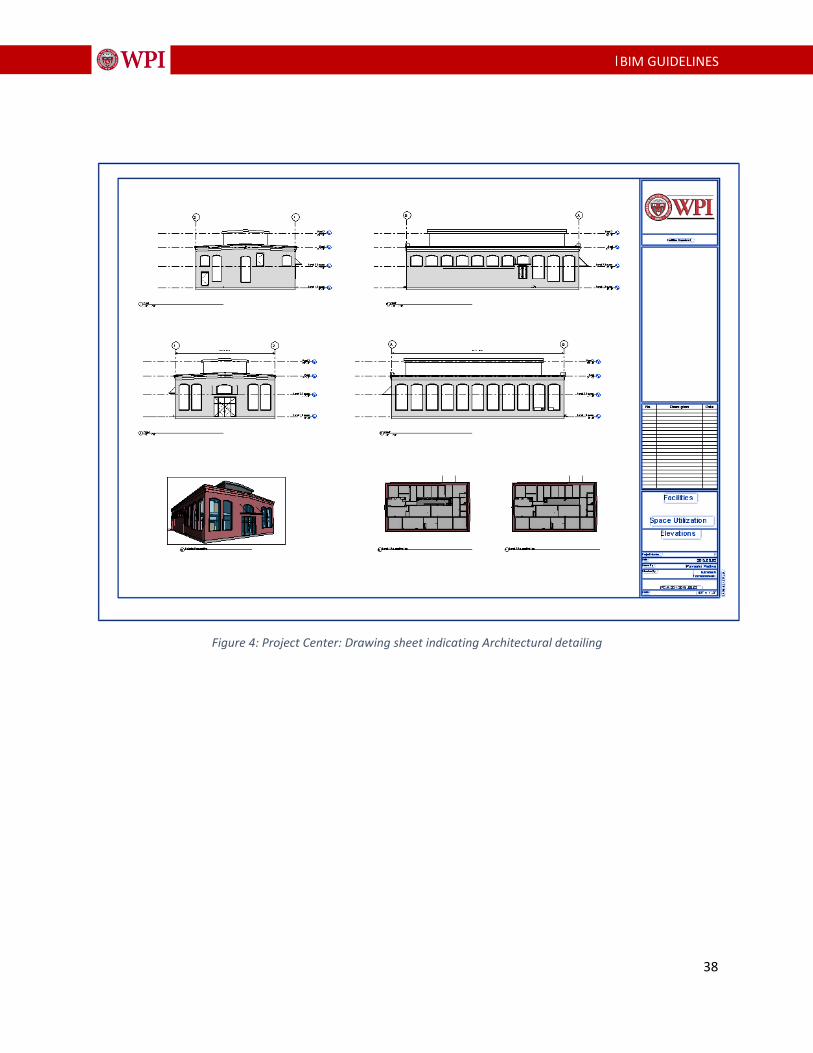
38
|BIM GUIDELINES
Figure 4: Project Center: Drawing sheet indicating Architectural detailing

39
|BIM GUIDELINES
Figure 5: Project Center: Drawing sheet indicating Space Use per FICM codes

40
|BIM GUIDELINES
Figure 6: Project Center: Drawing sheet indicating Space Use (door tags)

41
|BIM GUIDELINES
Figure 7: Project Center: Drawing sheet indicating Space Utilization and room capacities
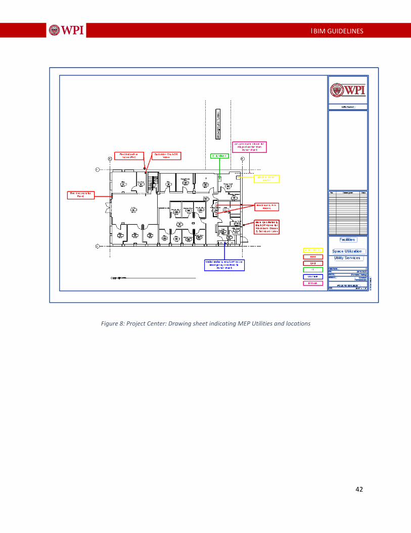
42
|BIM GUIDELINES
Figure 8: Project Center: Drawing sheet indicating MEP Utilities and locations

43
|BIM GUIDELINES
B i b l i o g r a p h y
https://www.specifiedby.com/resources/bim-dictionary
National BIM Standard-United States [online] Available at:
https://www.nationalbimstandard.org/files/NBIMS-US_FactSheet_2015.pdf
2012 BIM Smart Market Report: Business Value of BIM in North America [online] Available at:
https://oliebana.com/2012/12/09/2012-bim-smart-market-report-business-value-of-bim-in-
north-america/

44
|BIM GUIDELINES
T e r m i n o l o g y
A
As-Built Documents
As-built documents are the collection of paper drawings or electronic drawings that typically
reside in the contractor’s onsite trailer that contain mark-ups, annotations, and comments about
changes that have been made to the contract documents during the construction phase.
As-Built Model
Design Intent Models that have been updated throughout the construction process. These
changes and updates have been communicated from the Contractor to the Design Team through
the comments, annotations, and mark-ups from the As-Built Documents. These typically, but not
always, are discipline specific models.
B
BIM Execution Plan (BEP)
A plan that is created from the WPI BIM Execution Plan Template that is to be submitted thirty
days after contract award. The BEP helps to define roles and responsibilities within a project
team.
BIM Proficiency Matrix (BPM)
A matrix designed to measure the expertise of a firm as it relates to using a BIM process on
projects. It will be used as one of the many selection criteria during the selection process.
C
45
|BIM GUIDELINES
COBie - Construction Operations Building Information Exchange
COBie is a standard of information exchange that allows information to be captured during
design and construction in a format that can be used during the operations of a building once
completed.
Critical Path Modeling
Critical Path Modeling is a method of demonstrating Integrated Project Delivery, and tied to the
AIA E202 level of development approach. It sets a plan within the design team that accounts for
the activities of each discipline and how they interact with each other. It builds upon a critical
path method for those activities, and allows the project team to schedule a complete project.
D
Design Team
The Design Team is considered the Architect and all of the consultants that provide design
services for a project. These design services can be rendered at any time during the project.
DWF
DWF is a file type developed by Autodesk to be locked and non-editable file for drawing sheets
and model data. It can be used as a file transfer for estimating data, markups, and other third
party software. It can be a combination of 3D and 2D information within the same file.
DWG
DWG is a native AutoCAD file format. It is a widely-used3 file format for exchanging drawing
information and 3D information to different programs. While not a database file type, it still has
lots of uses for exchanging information.

46
|BIM GUIDELINES
E
EIM - Energy Information Model
EIM is a concept of producing a “light” and “lean” model that can be used for simulating the
building’s performance very early within the design process. The EIM is the process of modeling
only the exterior envelope, and the interior volumes to produce a model that energy modeling
software can use.
F
FICM - Post Secondary Facilities Inventory and Classification Manual
FICM is standard that describes practices for initiating, conducting, reporting, and maintaining an
institutional facilities inventory.
I
IPD - Integrated Project Delivery
IPD describes a contractual relationship between all members of the project team including the
Owner, Designers, Consultants, and Construction teams. It is a project delivery method that
integrates people, systems, business structure and practices into a process that collaboratively
harness the talents and insights of all participants to optimize project results, increase value to
the owner, reduce waste, and maximize efficiency through all phases of design, fabrication, and
construction.
IPD Methodology

47
|BIM GUIDELINES
IPD Methodology is a concept that uses methods from the IPD contracts, but does not have the
contracts actually in place. It idealizes the concepts of integration of all team members to try
and benefit the entire project.
IPP Methodology Plan
The IPP Methodology Plan is a declaration of how the project team will achieve the goals of an
IPP Methodology. The plan can have several components and is encouraged to be part of the
BEP. The completion of a Reverse Phase Schedule or Critical Path Modeling is two examples of
an IPD Methodology Plan.
L
LEED
The Leadership in Energy and Environmental Design (LEED) Green Building Rating System is a
suite of standards for environmentally sustainable construction. Based on a point system, a
building can achieve different ratings based on the performance of the design, construction, and
operation of the building.
N
NavisWorks
NavisWorks is software that allows for the viewing of multiple model formats. This ability to
“view” these files also allows NavisWorks to simulate the interaction between model files. That
includes interference reporting, time lining, and coordination.
NWC
48
|BIM GUIDELINES
An. NWC file is a NavisWorks Cache File that is used by NavisWorks to quickly read many other
file types. All linked files in NavisWorks have an .NWC file created automatically. In addition,
Revit will export directly to the very small file type of .NWC for quick access by NavisWorks.
NWD
A much larger file than the .NWC, the .NWD file shows snapshots in time of a NavisWorks file.
No linked files exist but all geometry is included.
NWF
The .NWF file is a native NavisWorks file that has all linked files, interferences/ collisions,
markups, animations, schedules, etc.
O
Open Architecture
Open Architecture is a concept of creating a framework that helps to describe a common set of
rules for how a project is created. This includes what types of software, the interoperability of
the information, and how the participants interact with each other. This is different from open
standards in that it promotes progress while not anchoring forward thinkers to a rigid standard.
P
Phases
The phases of a project can be described in two different ways as the adoption of IPD
terminology starts to penetrate the BIM Execution Plan and the IPD Methodology Plan. Below is
a list of the traditional names followed by the IPD name.
Pre-Design/Conceptualization Phase
49
|BIM GUIDELINES
Schematic Design/Criteria Design Phase
Design Development/Detailed Design Phase
Construction Documents/Implementation Phase
Project Team
The Project Team is considered the combination of the Design Team, Contractor, and at times,
GT faculty; a complete team needed to make holistic project decisions and approvals.
R
Record Drawing
The production of Record Drawings is the capturing of the As-Built Document’s annotation,
comments, and mark-ups in a drawing format only. This does not typically include the updating
of any models.
Reverse Phase Scheduling
Reverse Phase Scheduling Is a method of demonstrating Integrated Project Delivery. It sets a
plan within the design team that accounts for the activities of each discipline and how they
interact with each other. It uses the completion date as a point to work backward from to
schedule all of the project’s activities.
RVT
An .RVT file is a Revit native file type. It is also the deliverable file format for all projects. This
includes all the Design Team’s models.