Embed Size (px)
Citation preview
Pergamon
08!%6875(01)00056-5
Mincrdr En@~eerin& Vol. 14, No. 6; pp. 647-659.2001 0 2001 Published by Elsevier Science Ltd
All rights mserved 0892-6875/01/$ - see front matter
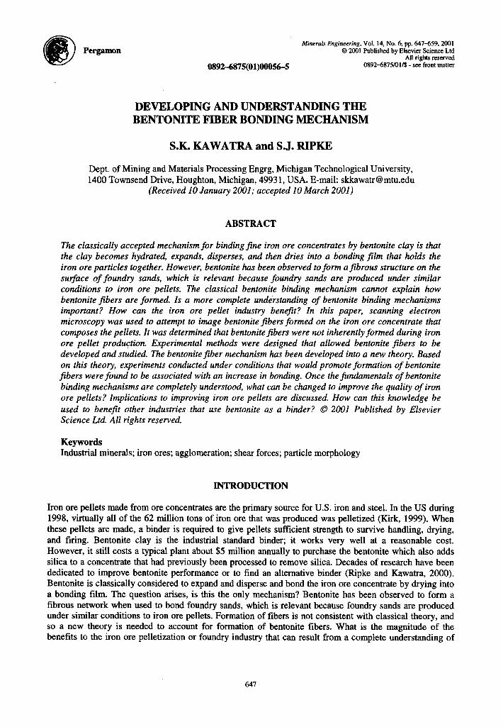
DEVELOPING AND UNDERSTANDING THE BENTONITE FIBER BONDING MECHANISM
S.K. KAWATRA and S.J. RIPKE
Dept. of Mining and Materials Processing Engrg, Michigan Technological University, 1400 Townsend Drive, Houghton, Michigan, 49931, USA. E-mail: [email protected]
(Received 10 January 2001; accepted 10 March 2001)
ABSTRACT
The classically accepted mechanism for binding fine iron ore concentrates by benfonife clay is that the clay becomes hydrated, expands, disperses, and then dries info a bonding film that holds the iron ore particles together. However, benfonife has been observed to form a fibrous strucfure on the surface of foundry sands, which is relevant because foundry sands are produced under similar conditions to iron ore pellets. The classical bentonite binding mechanism cannot explain how bentonite @fibers are formed. Is a more complete understanding of bentonife binding mechanisms importanf? How can the iron ore pellef industry benefit? In this paper, scanning electron microscopy was used to attempt to image bentonite fibers formed on the iron ore concentrate that composes the pellets. It was determined that bentonite fibers were not inherently formed during iron ore pellet production. Experimental methods were designed that allowed bentonite fibers to be developed and studied. The bentonitefiber mechanism has been developed into a new theory. Based on this theory, experiments conducted under conditions that would promote formation of bentonite fibers were found to be associated with an increase in bonding. Once the fundamentals of bentonite binding mechanisms are completely understood, what can be changed to improve the quality of iron ore pellets? Implicafions to improving iron ore pellets are discussed. How can this knowledge be used fo benefit other industries that use bentonite as a binder ? 0 2001 Published by Elsevier Science Ltd. All rights reserved.
Keywords Industrial minerals; iron ores; agglomeration; shear forces; particle morphology
INTRODUCTION
Iron ore pellets made from ore concentrates are the primary source for U.S. iron and steel. In the US during 1998, virtually all of the 62 million tons of iron ore that was produced was pelletized (Kirk, 1999). When these pellets are made, a binder is required to give pellets sufficient strength to survive handling, drying, and firing. Bentonite clay is the industrial standard binder; it works very well at a reasonable cost. However, it still costs a typical plant about $5 million annually to purchase the bentonite which also adds silica to a concentrate that had previously been processed to remove silica. Decades of research have been dedicated to improve bentonite performance or to find an alternative binder (Kipke and Kawatra, 2000). Bentonite is classically considered to expand and disperse and bond the iron ore concentrate by drying into a bonding film. The question arises, is this the only mechanism? Bentonite has been observed to form a fibrous network when used to bond foundry sands, which is relevant because foundry sands are produced under similar conditions to iron ore pellets. Formation of fibers is not consistent with classical theory, and so a new theory is needed to account for formation of bentonite fibers. What is the magnitude of the benefits to the iron ore pelletization or foundry industry that can result from a complete understanding of
647
648 S. K. Kawatra and S. J. Ripke
bentonite bonding mechanisms? Experiments explained in this paper show that bentonite is difficult to see within an iron ore pellet. Therefore, experiments were designed to develop and allow the study of bentonite fibers. The ability of bentonite to form fibers is explained based on a qualitative model and developed into a new binding mechanism that contrasts and compliments the classical theory. In addition, when bentonite fibers were developed, the bonding was shown to improve. The bentonite fiber theory can now be applied to iron ore pelletization to determine process conditions that can produce stronger pellets or reduce the bentonite dosage.
BACKGROUND
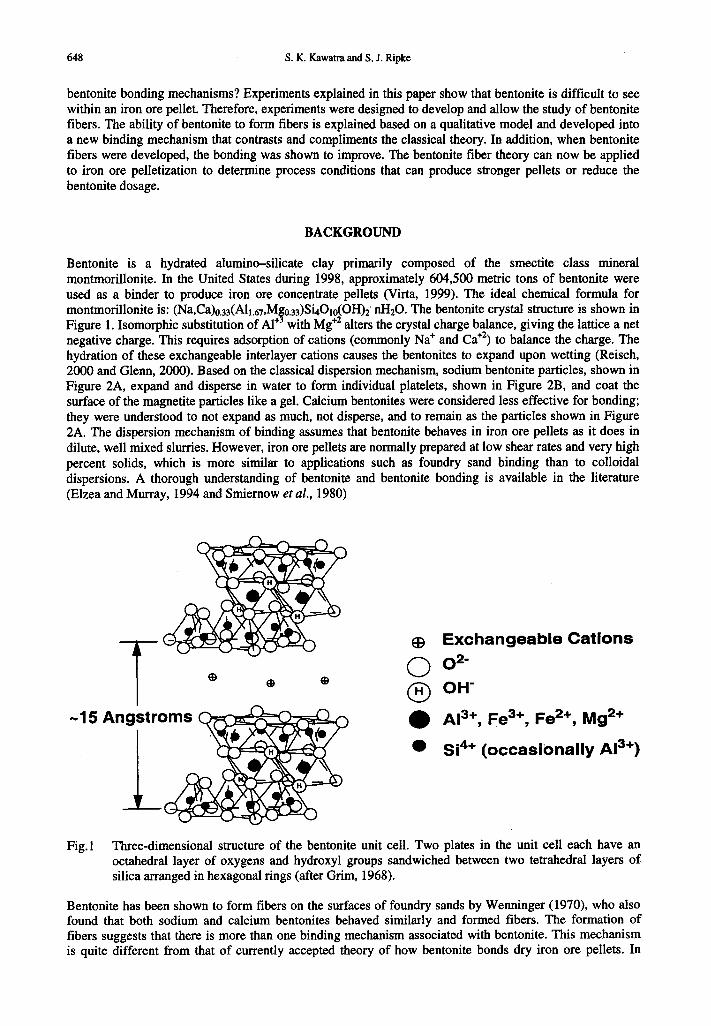
Bentonite is a hydrated alumin+silicate clay primarily composed of the smectite class mineral montmorillonite. In the United States during 1998, approximately 604,500 metric tons of bentonite were used as a binder to produce iron ore concentrate pellets (Virta, 1999). The ideal chemical formula for montmorillonite is: (Na,Ca)O.s~(A1i.~r,M$ o 33)S&010(OH)2’ nHzO. The bentonite crystal structure is shown in . Figure 1. Isomorphic substitution of Al+ with Mg+’ alters the crystal charge balance, giving the lattice a net negative charge. This requires adsorption of cations (commonly Na+ and Ca”) to balance the charge. The hydration of these exchangeable interlayer cations causes the bentonites to expand upon wetting (Reisch, 2000 and Glenn, 2000). Based on the classical dispersion mechanism, sodium bentonite particles, shown in Figure 2A, expand and disperse in water to form individual platelets, shown in Figure 2B, and coat the surface of the magnetite particles like a gel. Calcium bentonites were considered less effective for bonding; they were understood to not expand as much, not disperse, and to remain as the particles shown in Figure 2A. The dispersion mechanism of binding assumes that bentonite behaves in iron ore pellets as it does in dilute, well mixed slurries. However, iron ore pellets are normally prepared at low shear rates and very high percent solids, which is more similar to applications such as foundry sand binding than to colloidal dispersions. A thorough understanding of bentonite and bentonite bonding is available in the literature (Elzea and Murray, 1994 and Smiernow er al., 1980)
Exchangeable Cations
02’ OH’
A13+, Fe3+, Fe*+, Mg*+
Si4+ (occasionally A13+)
Fig.1 Three-dimensional structure of the bentonite unit cell. Two plates in the unit cell each have an octahedral layer of oxygens and hydroxyl groups sandwiched between two tetrahedral layers of silica arranged in hexagonal rings (after Grim, 1968).
Bentonite has been shown to form fibers on the surfaces of foundry sands by Wenninger (1970), who also found that both sodium and calcium bentonites behaved similarly and formed fibers. The formation of fibers suggests that there is more than one binding mechanism associated with bentonite. This mechanism is quite different from that of currently accepted theory of how bentonite bonds dry iron ore pellets. In
Developing and understanding the bentonite fiber bonding mechanism 649
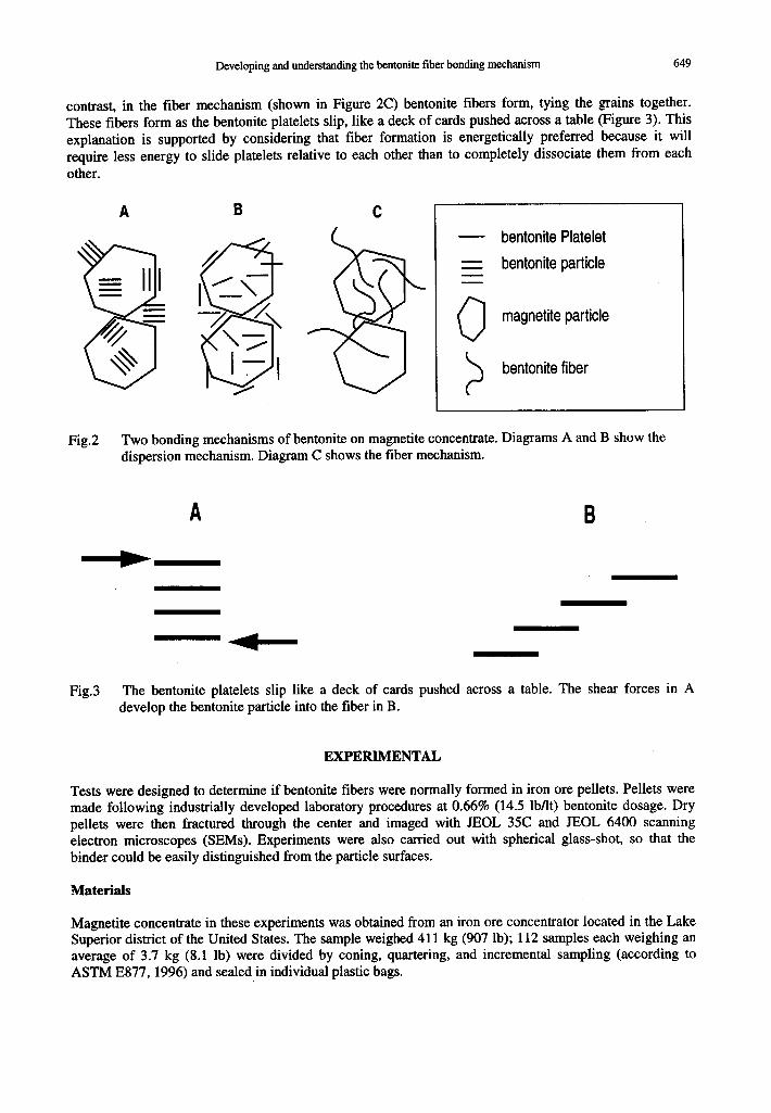
contrast, in the fiber mechanism (shown in Figure 2C) bentonite fibers form, tying the grains together. These fibers form as the bentonite platelets slip, like a deck of cards pushed across a table (Figure 3). This explanation is supported by considering that fiber formation is energetically preferred because it will require less energy to slide platelets relative to each other than to completely dissociate them from each other.
- bentonite Platelet
=: bentonite particle - -
0 magnetite particle
>
bentonite fiber
Fig.2 Two bonding mechanisms of bentonite on magnetite concentrate. Diagrams A and B show the dispersion mechanism. Diagram C shows the fiber mechanism.
Fig.3 The bentonite platelets slip like a deck of cards pushed across a table. The shear forces in A develop the bentonite particle into the fiber in B.
EXPERIMENTAL
Tests were designed to determine if bentonite fibers were normally formed in iron ore pellets. Pellets were made following industrially developed laboratory procedures at 0.66% (14.5 lb/h) bentonite dosage. Dry pellets were then fractured through the center and imaged with JEOL 3X and JEOL 6400 scanning electron microscopes (SEMs). Experiments were also carried out with spherical glass-shot, so that the binder could be easily distinguished from the particle surfaces.
Materials
Magnetite concentrate in these experiments was obtained from an iron ore concentrator located in the Lake Superior district of the United States. The sample weighed 411 kg (907 lb); 112 samples each weighing an average of 3.7 kg (8.1 lb) were divided by coning, quartering, and incremental sampling (according to ASTM E877, 1996) and sealed in individual plastic bags.
650 S. K. Kawatra and S. J. Ripke
The concentrate had 10% moisture, a particle size of 80% passing 25 microns (500 mesh), and contained 4.9% gangue, essentially consisting of crystalline quartz.
The glass-shot was obtained from Microbeads Inc. of Jackson, Mississippi. This glass had a virtually spherical morphology. The particle size was 80% passing 121 microns with a narrow size distribution of 95% of the material between 62 and 176 microns.
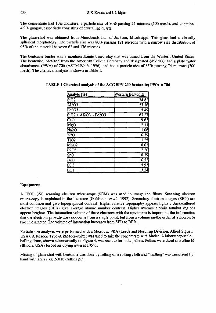
The bentonite binder was a montmorillonite based clay that was mined from the Western United States. The bentonite, obtained from the American Colloid Company and designated SPV 200, had a plate water absorbance, (PWA) of 706 (ASTM E946, 1996), and had a particle size of 85% passing 74 microns (200 mesh). The chemical analysis is shown in Table 1.
TABLE 1 Chemical analysis of the ACC SPV 200 bentonite; PWA = 706
Equipment
A JEOL 35C scanning electron microscope (SEM) was used to image the fibers. Scanning electron microscopy is explained in the literature (Goldstein, et al., 1992). Secondary electron images (SEIs) are most common and give topographical contrast. Higher relative topography appears lighter. Backscattered electron images (BEIs) give average atomic number contrast. Higher average atomic number regions appear brighter. The interaction volume of these electrons with the specimens is important; the information that the electrons provide does not come from a single point, but from a volume onthe order of a micron or two in diameter. The volume of interaction increases from SEIs to BEIs.
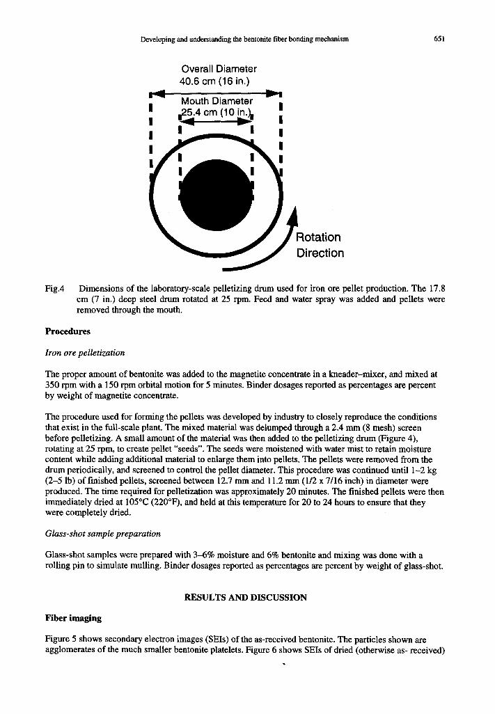
Particle size analyses were performed with a Microtrac SRA (Leeds and Northrup Division, Allied Signal, USA). A Readco Type-A kneader-mixer was used to mix the concentrate with binder. A laboratory-scale balling drum, shown schematically in Figure 4, was used to form the pellets. Pellets were dried in a Blue M (Illinois, USA) forced air drying oven at 105°C.
Mixing of glass-shot with bentonite was done by rolling on a rolling cloth and “mulling” was simulated by hand with a 2.28 kg (5.0 lb) rolling pin.
Developing and understanding the bentonite fiber bonding mechanism 651
Overall Diameter 40.6 cm (16 in.)
Fig.4 Dimensions of the laboratory-scale pelletizing drum used for iron ore pellet production. The 17.8 cm (7 in.) deep steel drum rotated at 25 rpm. Feed and water spray was added and pellets were removed through the mouth.
Procedures
Iron ore pelletization
The proper amount of bentonite was added to the magnetite concentrate in a kneader-mixer, and mixed at 350 rpm with a 150 rpm orbital motion for 5 minutes. Binder dosages reported as percentages are percent by weight of magnetite concentrate.
The procedure used for forming the pellets was developed by industry to closely reproduce the conditions that exist in the full-scale plant. The mixed material was delumped through a 2.4 mm (8 mesh) screen before pelletizing. A small amount of the material was then added to the pelletizing drum (Figure 4), rotating at 25 rpm, to create pellet “seeds”. The seeds were moistened with water mist to retain moisture content while adding additional material to enlarge them into pellets. The pellets were removed from the drum periodically, and screened to control the pellet diameter. This procedure was continued until l-2 kg (2-5 lb) of finished pellets, screened between 12.7 mm and 11.2 mm (l/2 x 7/16 inch) in diameter were produced. The time required for pelletization was approximately 20 minutes. The finished pellets were then immediately dried at 105°C (220’F), and held at this temperature for 20 to 24 hours to ensure that they were completely dried.
Glass-shot sample preparation
Glass-shot samples were prepared with 3-6% moisture and 6% bentonite and mixing was done with a rolling pin to simulate mulling. Binder dosages reported as percentages are percent by weight of glass-shot.
RESULTS AND DISCUSSION
Fiber imaging
Figure 5 shows secondary electron images (SEIs) of the as-received bentonite. The particles shown are agglomerates of the much smaller bentonite platelets. Figure 6 shows SEIs of dried (otherwise as- received)
652 S. K. Kawatra and S. J. Ripke
magnetite concentrate. The SEIs in Figure 7 show that fibers were not obvious in iron ore pellets; the ber itonite remained as particles.
Fig .5 Secondary electron images (SEI) of the as-received ACC SPV 200 bentonite. Top: magnification, 100 micron scalebar. Bottom: 2600 X, 10 micron scalebar.
1260 X
Since fibers were not inherent to iron ore pellets and the bentonite remained as particles, naturally, the next question to be asked was: Can bentonite fibers be developed under conditions suitable for iron ore pelletization? It was difficult to visually discern the magnetite from the bentonite particles, because the magnetite has fine particles that appear similar to the bentonite particles and the bentonite is at a very low concentration. Therefore, another substrate was used to bond with bentonite that would give better contrast. Samples were then prepared with glass-shot and 6% bentonite.
Fig.6
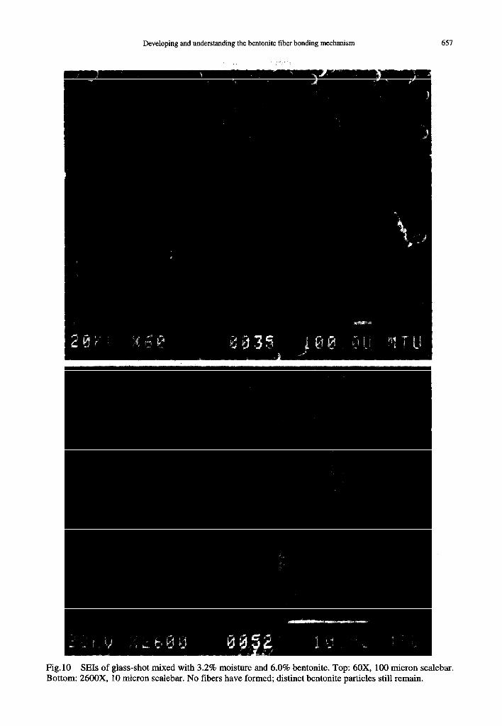
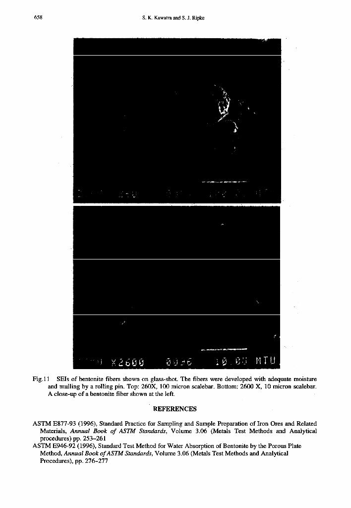
Figure :8 shows SEIs of the as-received glass-shot. Figure 9 shows two samples of the glass- with 6 I% bentonite under different mixing and moisture conditions. Sample A remains free-i not ha ve enough moisture or mixing to develop fibers, as shown in Figure 10. Sample B did moistr Ire : and mixing and developed fibers, as shown in Figure 11. The bentonite became mc a bind er after the fibers formed.
Developing and understanding the bentonite fiber bonding mechanism
SEIs of the as-received magnetite concentrate dried at 105°C. Top: 260X, 100 mia
Bottom: 2600X 10 microns scalebar. .on scalebar
,shc It prepan No1 wing and I ha Lve enoug ore effective
653
:d did ;h : as
654 S. K. Kawatra and S. J. Ripke
Fig.7 SEIs of a fracture surface of the magnetite concentrate pellet bonded with 0.66% American Colloid Company (ACC) SPV200 bentonite binder at 9.1% moisture, dried at 105°C Top: 240X . 100 micron scalebar. Bottom: 2600X 10 micron scalebar.
Bentonite fibers formed on the glass-shot when the mixture was hand-mulled at a sufficient moisture content, but were not evident on the magnetite particles when the conventional kneader-mixer was used. The obvious difference was the type of mixing. It was therefore hypothesized that mulling applied a shear force that developed the bentonite particles into fibers and that mulling the bentonite into the concentrate could result in improved bentonite performance.
Developing and understanding the bentonite fiber bonding mechanism 655
Fig.8 SEIs of the glass-shot. The spherical morphology is apparent. Top: 60X, 100 micron scalebar. Bottom: 2600X, 10 micron scalebar. The surface is relatively smooth.
656 S. K. Kawatra and S. J. Ripke
Fig.9 Unmagnified photo of glass-shot. Material A (left) is free flowing glass-shot plus bentonite without adequate mulling and moisture and is also shown in Figures 13 and 14. Material B (right) is the same as A with additional moisture and mulling and is also shown in figures 15 and 16. Material B has developed fibers and has become granular. The bentonite became more effective after the fibers formed. The upper scale bar represents 1 cm.
CONCLUSIONS
l Bentonite fibers were not inherent to the iron ore pellets that were made using conventional mixing. l Bentonite clay formed fibers on glass-shot when prepared under proper moisture and mechanical
mixing conditions. l Bentonite became a more effective binder after fibers formed.
The main questions remaining to be answered are:
l Can stronger iron ore pellets be made after bentonite is developed into a fibrous matrix? l Can the bentonite dosage be reduced in iron ore pellets if bentonite fibers are developed within them?
ACKNOWLEDGEMENTS
We would like to thank the Minnesota DNR for their generous financial support, Dr. Ron Wiegel of the NRRI, Mr. Peter Clevenstine of the Minnesota DNR, Paul Rosten, Ted Seppanen, and Steven G. Rogers of Cleveland-Cliffs Inc., Ray Potts and Bob Strukel of USX, Jim Wennen, Sarah Blust and Dennis Murr of NSPC, Bob Anderson of Eveleth Mines, Chris Glenn of American Colloids Co., and Dr. Tim Eisele of Michigan Tech for their invaluable technical advice. We would also like to thank undergraduate students: Toby Lee, Kari Buckmaster, Karla Andrade, Frank Perras, Elise Anderson, and Jaime Krull.
Developing and understanding the bentonite fiber bonding mechanism 657
Fig. 10 SEIs of glass-shot mixed with 3.2% moisture and 6.0% bentonite. Top: 60X, 100 micron scale Bou tom: 2600X, 10 micron scalebar. No fibers have formed; distinct bentonite particles still remain.
:bar.
S. K. Kawatra and S. J. Ripke
Fig.1 1 SEIs of bentonite fibers shown on glass-shot. The fibers were developed with adequate moist and mulling by a rolling pin. Top: 260X, 100 micron scalebar. Bottom: 2600 X, 10 micron scale1 A close-up of a bentonite fiber shown at the left.
:ure bar.
REFERENCES
ASTM E877-93 (1996), Standard Practice for Sampling and Sample Preparation of Iron Ores and Related Materials, Annual Book of ASTM Standards, Volume 3.06 (Metals Test Methods and Analytical procedures) pp. 253-261
ASTM E946-92 (1996), Standard Test Method for Water Absorption of Bentonite by the Porous Plate Method, Annual Book of ASTM Standards, Volume 3.06 (Metals Test Methods and Analytical Procedures), pp. 276-277
Developing and understanding the bentonite fiber bonding mechanism 659
Elzea, Jessica and Haydn H. Murray (1994), Bentonite; Z&&.zi Minerals and Rocks, (Donald D. Carr, ed.) Society for Mining, Metallurgy, and Exploration, AIME, pp. 223-246
Goldstein, J. I., D. E. Newbury, P. Echlin, D. C. Joy, A. D. Romig, Jr., C. E. Lyman, C. Fiori, and E. Lifshin (1992), Scanning Electron Microscopy and X-Ray Microanalysis, second Ed., Plenum Press, New York
Grim, R. E. (1968), Clay Mineralogy, 2nd Ed, McGwaw-Hill, New York, p. 79 Kirk, W. S. (1999), U.S. Geological Survey, Minerals Information, available by the World-Wide-Web,
http://minerals.er.usgs.gov/minerals/pubs/commodity/iron_ore/340398.pdf Reisch, Franz J. (2000), Manager of Minerals Development, American Colloid Company, personal
communication Ripke, S. Jayson and S. Komar Kawatra (2000) Can Fly-Ash Extend Bentonite Binder for Iron Ore
Agglomeration, International Journal of Mineral Processing, Elsevier Press, Vol. 60, pp. 181-198 Smiernow, G. A., E. L. Doheny, and J. G. Kay (1980), Bonding Mechanisms in Sand Aggregates, AFS
Transactions, Proceedings of the Eighty-fourth annual meeting, April 21-25, pp. 6.59-682 Virta, R. L. (1999), U.S. Geological Survey, Minerals Information, available by the World-Wide-Web,
http://minerals.er.usgs.gov/minerals/pubs/commodity/clays/l90399.pdf Wenninger, C. E. (1970), Water-Clay Entities on Grain Surfaces as Defined by a Scanning-type Electron
Microscope, AFS Transactions, American Foundrymen’s Society, Proceedings of the Seventy-Fourth Annual Meeting, Vol. 78
Correspondence on papers published in Minerals Engineering is invited by e-mail to bwills @min-eng.com