Embed Size (px)
Citation preview

Composite Structures 256 (2021) 113111
Contents lists available at ScienceDirect
Composite Structures
journal homepage: www.elsevier .com/locate /compstruct
Developing an innovative curved-pultruded large-scale GFRP arch beam
https://doi.org/10.1016/j.compstruct.2020.113111Received 10 June 2020; Revised 24 August 2020; Accepted 3 October 2020Available online 11 October 20200263-8223/© 2020 Elsevier Ltd. All rights reserved.
⇑ Corresponding author.E-mail addresses: [email protected] (T. Liu), [email protected] (P. Feng), [email protected] (Y. Wu), [email protected] (
[email protected] (X. Meng).
TianQiao Liu a, Peng Feng a,⇑, Yuwei Wu a, Shuxin Liao b, Xinmiao Meng c
aDepartment of Civil Engineering Tsinghua University, Beijing, ChinabCentral South University, Changsha, ChinacDepartment of Civil Engineering, Beijing Forestry University, Beijing, China
A R T I C L E I N F O
Keywords:FRP composite materialsCurved‐Pultrusion techniqueBuckling behaviorsFlexural behaviorsFull‐scale Pedestrian bridge
A B S T R A C T
An arch glass fiber reinforced polymer (GFRP) I‐beam with a 600 mm height was developed based on the latestcurved‐pultrusion technique to overcome the most critical design issues of large‐scale GFRP beams, includingexcessive deflections and premature buckling failures. To achieve this goal, a review was first conductedregarding the complex buckling behaviors of pultruded GFRP beams, building a theoretical basis for the devel-opment of the curved beam. Then, a series of three‐point bending tests for beams were conducted at full scale,in which the typical failure modes, load‐carrying capacities and deflection and strain data were obtained.Compression flange delamination was found to be the dominant failure mode. The load–strain curves for flangeand web plates demonstrated that the proposed beams were exempt from local buckling issues. Additionally,an analytical study and finite element modeling were carried out. Excellent agreement between experimental,analytical and numerical studies was observed. The design approach for conventional straight profiles is readilyapplicable to curved beams as the difference is limited. In the end, a 20‐m‐long full‐scale GFRP pedestrianbridge was designed, constructed and tested. The great potential of the proposed curved‐pultruded GFRP archbeam was successfully demonstrated.
1. Introduction
Pultruded glass fiber reinforced polymer (GFRP) composite materi-als, with high strength‐ and stiffness‐to‐weight ratios, have seennumerous developments in the field of civil engineering in recent dec-ades [28,29,70]. Typical applications of pultruded GFRP profilesinclude both the main and secondary beams and columns in coolingtowers, pedestrian bridges and many types of frame structures[74–76]. In particular, pultruded GFRP beams, due to the relativelylow modulus of elasticity and the high anisotropy of the material, tendto exhibit a different behavior as compared to other beams made ofconventional materials such as concrete and steel [40,72].
First, pultruded GFRP beams may exhibit excessive deflectionunder the service limit state, which has substantially limited the possi-ble span length of the beam. Many studies have been conducted toevaluate the flexural behavior of pultruded GFRP beams. Bank [7,8]conducted a series of pioneering tests to investigate the flexural behav-ior of GFRP I‐beams and proposed a test method for determining theflexural and shear moduli. Nagaraj and GangaRao [50], Roberts andAl‐Ubaidi [57] and Estep et al. [26]also carried out bending tests on
GFRP I‐ and box‐beams, and in their tests, the flexural and shear stiff-ness were evaluated. Turvey [67] and Turvey and Zhang [69] studiedboth the major‐ and minor‐axis flexural behavior of GFRP I‐beams andproposed design equations to calculate the deflections and flexuralmodulus. Through all these studies, it has been identified that pul-truded GFRP beams tend to fail due to excessive deflection insteadof reaching the material strength limit state. Second, a number of stud-ies have also focused on the buckling behavior of pultruded GFRPbeams and found that premature buckling failure could significantlyreduce the ultimate load‐carrying capacities of the beam[15,47,48]). Indeed, pultruded GFRP profiles are commonly manufac-tured in the form of thin‐walled shapes and have a low elastic modulusand a high material anisotropy, making them highly susceptible tocomplex local and global buckling behaviors. In addition to the exces-sive deflection and complex buckling behaviors, other types of failuremodes have also drawn attention from the field. For instance, bothCorreia et al. [22] and Zuo et al. [77] have observed the web shear fail-ure of GFRP profiles in their tests studying the flexural behavior ofGFRP‐concrete hybrid beams.
S. Liao),

T. Liu et al. Composite Structures 256 (2021) 113111
Among all the possible failure modes of pultruded GFRP beams, thedeflection and buckling behaviors have been widely recognized as themost critical design factors [22]. In particular, the buckling behaviorsmay lead to the sudden catastrophic failure of the entire structures andhave been emphasized in almost all existing design guides, includingthose in the United States [1], Europe [27] and China [20]. Thus,the deflection and buckling behaviors of pultruded GFRP beams areof the focus in this work, and a priority is given to the latter. Withthe critical design issues identified, the main objective of this workis, therefore, to employ the latest curved‐pultrusion technique anddevelop an innovative curved‐pultruded GFRP arch beam capable ofmitigating adverse deformations as well as preventing prematurebuckling failures. To accomplish this objective, the latest curved‐pultrusion technique was introduced. Next, a review was conductedto acquire a comprehensive understanding of the typical bucklingmodes, as buckling is considered a prior to other design factors. Then,a new type of curved‐pultruded GFRP arch beam was proposed. Toinvestigate the flexural behavior of the proposed beam, three‐pointbending tests were carried out. Additionally, analytical and numericalstudies were conducted to evaluate and validate the flexural behaviorof the proposed beam. In the end, a full‐scale pedestrian bridge with aspan length of 20 m was designed and constructed using the proposedarch beam. This bridge is the first of its type worldwide and hasdemonstrated great potential for widespread applications of the pro-posed curved‐pultruded GFRP arch beam.
2. Curved-Pultrusion technique
In common practice of bridges, a camber is often introduced tosteel and concrete beams/girders to mitigate the adverse deflectionand to ensure the clearance under bridge. However, the conventionalpultrusion technique, namely the straight‐pultrusion process, can onlyproduce straight profiles [58], as shown in Fig. 1a. In this case, thecamber is not practically achievable, and consequently, a large deflec-tion is often inevitable. One common approach of reducing the verticaldeflection is to increase the section depth of GFRP beams, whichwould, however, lead to an increased cost of the material. In thisregard, the latest curved‐pultrusion technique was adopted to realizethe arch/cambered GFRP beam, as shown in Fig. 1b. In the curved‐pultrusion process (also referred to as the bent‐ or radius‐pultrusion), the GFRP section coming out of the forming and curingdie is further bent to a desired curvature at the pulling and curving sys-tem before the resin is completely hardened [18,63]. Typically, onlycircular curvature is permitted. The curved‐pultruded beam, namelythe arch/cambered beam, permits an offset to the adverse verticaldeflection, thus ensuring the required clearance under the beam aswell as satisfying the service limit state of the structure.
It is noted that to achieve the curvature of pultruded profiles, ultra-violet (UV) radiation can also be used. An early study on the use of UVradiation to produce curved‐pultruded profiles was conducted by Ken-nedy and Kusy [36], in which a 0.5‐mm‐diameter round quartz fiberreinforced composite profile was successfully produced. Then, Britnellet al. [18] adopted UV radiation instead of mechanical curving systemin pultruded process and produced a variety of structural shapes suchas the solid circular bar, and angle and box sections. Additionally,Tena et al. [62] further investigated the effect of emitting intensityof UV radiation and the pulling speed on the curved‐pultrusion pro-cess. Nonetheless, using UV radiation the geometries of curved‐pultruded profiles are often limited, such as those having 6 mm indiameter (the circular bar described in [18]) and 10 mm in width(the rectangular section described in [62]). Such a small geometrycan hardly be used in typical civil infrastructures. In this regard, thecurved‐pultrusion technique using mechanical curving system isfocused in this work. Recently, using such curved‐pultrusion techniqueTonatto et al. [64] produced a spiral beam having a radius of curvature
2
of 581 mm and a length of 335 mm, and its flexural behavior was stud-ied. They reported that the curved‐pultrusion technique, as comparedwith the filament winding process, could yield a more homogeneousfiber distribution, thus permitting an increased flexural strength. Inthe present work, a large‐scale curved‐pultruded I‐beam was studied.The section height of this beam is 600 mm, which is, by far, the largestin the available literature.
3. Review of buckling modes of pultruded GFRP beam
Excessive deflection and buckling behaviors have been identifiedby many researchers as the most critical design factors for GFRP struc-tures (Correia et al. [22], for instance). In particular, the bucklingbehavior may lead to catastrophic failure of the entire structure andthus, is given a precedence in this work. Representative studies havebeen systematically reviewed to acquire a comprehensive understand-ing of the buckling behaviors. It is noted that this review does not indi-cate that the buckling failure is the only failure mode of pultrudedGFRP beams. Other failure modes pertaining to strength limit stateshould be prevented through appropriate detailing. Typically, threetypes of buckling modes are of the highest interest in the field, includ-ing 1) flange local buckling (FLB) and/or web local buckling (WLB); 2)lateral torsional buckling (LTB); and 3) local section distortion (LSD)affected‐LTB, as shown in Fig. 2. In particular, FLB and WLB oftenoccur simultaneously as flange distortion could lead to the rotationof the web. Nonetheless, the flange plate is restrained only at oneend and the web plate is restrained at two ends, and the width offlange plate is often not greater than that of web plate; thus, FLBstrength is often much higher than WLB strength for a beam havingthe same flange and web thickness. In this regard, WLB due to flexuralbehavior of the beam is tpyically not a critical design concern and thus,is not specifically reviewed in this work. However, the web cripplingand web compression buckling (WCB) triggered by concentrated loadsare discussed.
3.1. Flange local buckling
Flange local buckling (FLB) (see Fig. 2a) often occurs in thin‐walledflexural members in which the flange plate is essentially subjected tocompression and tends to buckle prior to reaching the materialstrength limit state. The earliest study investigating the FLB behaviorof pultruded GFRP profiles dates back to the 1990s when Barberoet al. [15] conducted experimental tests on GFRP I‐ and box‐beamsand first observed the local buckling of the compression flange (seeFig. 3a). In their study, classic plate theory was used and the compres-sion flange was assumed to be a simply‐supported plate with one edgefree and the other restrained by the web plate via an elastic spring withrotational stiffness k, as shown in Fig. 3b. Barbero and Raftoyiannis[13] continued their work on predictive models by taking flange‐web junctions into consideration. Later, Bank et al. [11] highlighted,again, the impact of considering the restraining effect of flange‐webjunctions in the predictions of the local buckling loads. Bank et al.[10] also carried out bending tests on GFRP I‐beams and identifiedthat local buckling could trigger the complete failure of the beam.Then, Pecce and Cosenza [53], Qiao et al. [55] and Qiao and Zou[54] proposed design equations to predict the critical FLB stress andsimilar to previous studies, the flange plate was assumed to be elasti-cally restrained at the flange‐web junction.
In particular, Kollár [37] proposed a full suite of explicit designequations calculating the critical buckling loads for orthotropic plateswith various types of boundary conditions. Kollár’s equations are gen-erally taken as the benchmark solutions for the field and have beenadopted in American [1], European [27] and Chinese [20] designguides. Correia et al. [23] also carried out bending tests on GFRP I‐beams and again confirmed that pultruded GFRP profiles were gov-
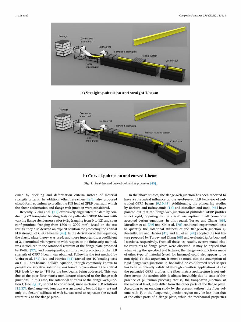
Fig. 1. Straight- and curved-pultrusion processes [45].
T. Liu et al. Composite Structures 256 (2021) 113111
erned by buckling and deformation criteria instead of materialstrength criteria. In addition, other reseachers [2,3] also proposedclosed‐form equations to predict the FLB load of GFRP beams, in whichthe shear deformation and flange‐web junction were considered.
Recently, Vieira et al. [71] extensively augmented the data by con-ducting 62 four‐point bending tests on pultruded GFRP I‐beams withvarying flange slenderness ratios b/2tf (ranging from 6 to 12) and spanconfigurations (ranging from 1800 to 2900 mm). Based on the testresults, they also derived an explicit solution for predicting the criticalFLB strength of GFRP I‐beams [43]. In the derivation of that equation,the classic plate theory was used, and more importantly, a coefficientof 2, determined via regression with respect to the finite strip method,was introduced to the rotational restraint of the flange plate proposedby Kollár [37], and consequently, an improved prediction of the FLBstrength of GFRP I‐beam was obtained. Following the test method byVieira et al. [71], Liu and Harries [41] carried out 10 bending testson GFRP box‐beams. Kollár’s equation, though commonly known toprovide conservative solutions, was found to overestimate the criticalFLB loads by up to 41% for the box‐beams being addressed. This wasdue to the poor fiber‐matrix architecture observed at the flange‐webjunctions. In this case, the rotational stiffness of the flange‐web junc-tion kj (see Fig. 3c) should be considered, since in classic FLB solutions[15,37], the flange‐web junction was assumed to be rigid (kj =∞) andonly the flexural stiffness of web kw was used to represent the overallrestraint k to the flange plate.
3
In the above studies, the flange‐web junction has been reported tohave a substantial influence on the as‐observed FLB behavior of pul-truded GFRP beams [9,10,43]. Additionally, the pioneering studiesby Barbero and Raftoyiannis [13] and Mosallam and Bank [48] havepointed out that the flange‐web junction of pultruded GFRP profilesis not rigid, opposing to the classic assumption in all commonlyaccepted design equations. In this regard, Turvey and Zhang [68],Mosallam et al. [79] and Xin et al. [78] conducted experimental teststo quantify the rotational stiffness of the flange‐web junction kj.Recently, Liu and Harries [41] and Liu et al. [44] adopted the test fix-ture proposed by Turvey and Zhang [68] and evaluated kj for box‐ andI‐sections, respectively. From all these test results, overestimated elas-tic restraints to flange plates were observed. It may be argued thatwhen using the specified test fixtures, the flange‐web junctions madeof other type of material (steel, for instance) could also appear to benon‐rigid. To this argument, it must be noted that the assumption ofrigid flange‐web junctions in hot‐rolled or cold‐formed steel shapeshas been sufficiently validated through countless applications. As forthe pultruded GFRP profiles, the fiber–matrix architecture is not uni-form across the section (this is almost inevitable due to state‐of‐the‐practice of pultrusion process); that is, the flange‐web junction, atthe material level, may differ from the other parts of the flange plate.According to an ongoing study by the present authors, the fiber vol-ume ratio Vf at the flange‐web junction region may be less than thatof the other parts of a flange plate, while the mechanical properties

Fig. 2. Typical buckling modes of GFRP I-beams subjected to three-pointbending [42].
T. Liu et al. Composite Structures 256 (2021) 113111
used in calculating the rotational stiffness as well as the critical FLBstrength are those measured at the flange plate (in fact, no standardcoupon can be extracted from flange‐web junction region). With theactual kj considered, the predicted FLB strength could be improved,particularly for beams having a poor fiber‐matrix architecture at theflange‐web junctions [41].
3.2. Web crippling and compression buckling
In addition to the local buckling of flange plates, Borowicz andBank [16,17] investigated the possible failure modes of web plates.Borowicz and Bank [16] first tested 20 GFRP I‐beams subjected to con-centrated loads and identified interlaminar shear strength‐dominated
Fig. 3. Flange-web junction restraint
4
web crippling failure, which was characterized by shear failure atthe flange‐web junction. The corresponding design equation wasdeveloped and has been adopted by ASCE Prestandard [1]. In particu-lar, the bearing plate was found to provide an additional capacity tothe beam with regard to web crippling failure. Then, Borowicz andBank [17] tested five deep GFRP I‐beams subjected to concentratedloads and observed a web buckling‐dominated failure mode. Differingfrom the beams that failed due to the material strength‐dominated webcrippling failure, the bearing plate showed little impact on the ultimatecapacity of the beam failed due to web compression buckling, whcih isthe stability‐dominated failure mode. Kollár’s equation was, again,reported to greatly underestimate the web buckling strength, approx-imately by a factor of 2.
3.3. Lateral torsional buckling
Lateral torsional buckling (LTB) (see Fig. 2b) is a typical designconcern, particularly when the compression flange is only intermit-tently or minimally laterally supported, such as those flexural mem-bers in cooling towers and truss bridges. To investigate the LTBbehavior of pultruded GFRP profiles, a number of studies have beenconducted. Mottram [49] conducted experimental tests on GFRP I‐beams, in which the LTB behavior was observed and found to be extre-mely sensitive to imperfections in the test setup. Later, Brooks and Tur-vey [19] used a different test configuration, cantilever bending test, tostudy the LTB behavior of GFRP I‐beams. Pandey et al. [52] extendedthe flexural tests on GFRP I‐beams by using different load patterns. Inaddition, Turvey [65,66] carried out tests on cantilever box‐ and I‐beams. A design formula, modified from that for isotropic material,was found to have a good agreement for those beams having relativelyhigh span‐to‐depth ratios. In a numerical study, Lin et al. [39] con-structed a finite element (FE) model to investigate the LTB behaviorof GFRP beams and shear deformation was found to have a moreprominent impact on the orthotropic GFRP materials when comparedto the isotropic materials.
In addition, Davalos et al. [25] developed an analytical solutionbased on the principle of the minimum potential energy. Sapkás andKollár [59] also developed explicit design equations to predict theLTB loads of GFRP beams and various load patterns were considered.Later, Qiao et al. [56] and Correia et al. [23] conducted flexural testson cantilever GFRP I‐beams and developed analytical solutions to pre-dict the LTB loads. Once again, it was confirmed that the pultrudedGFRP beams were essentially governed by deformation criteria ratherthan material strength criteria [23]. In addition, Ascione et al. [4] pro-posed a numerical model for predicting the LTB loads of GFRP I‐beams. Nguyen et al. [51] experimentally evaluated the effect of loadpositions on LTB behavior of GFRP I‐ and Channel‐beams; for instance,the beams loaded at the centroid exhibited LTB loads approximately
of pultruded GFRP I-beam [44].

T. Liu et al. Composite Structures 256 (2021) 113111
40% higher than those loaded at the top flange. Recently, Vieira et al.[71] conducted 86 three‐point bending tests on GFRP I‐beams, inwhich five different I‐sections were loaded under five span configura-tions, resulting in a total of 25 different lateral slenderness ratiosLb/ry, ranging from 42 to 301 (ry is the radius of gyration about they‐axis). Based on the test results, they also derived an explicit designequation for predicting the critical LTB loads of GFRP I‐beams sub-jected to various types of load patterns [42]. Similar to the findingsfrom [64], this design equation was only able to provide accurate solu-tions for those beams with relatively high lateral slenderness ratios(Lb/ry > 100, for instance), while for those beams with lower lateralslenderness ratios (Lb/ry < 100, for instance), local section distortion(LSD) was observed and found to affect the buckling strength. In addi-tion, Zeinali et al. [73] experimentally and numerically evaluated theLTB of pultruded GFRP I‐beams subjected to pure bending, and thedesign equation for steel sections was found to be valid for slenderGFRP beams.
3.4. Local section distortion affected lateral torsional buckling
As aforementioned, lateral torsional buckling is typically the dom-inant behavior for GFRP beams with high lateral slenderness ratios[42,64], whereas for GFRP beams with intermediate lateral slender-ness ratios, various extents of the flange and/or web local buckling/de-formation may occur accompanying the global LTB behavior,substantially reducing the buckling strength of the beam. This typeof buckling mode may be referred to as interactive buckling [35]and coupled lateral and distortional buckling [14]. Based on the prac-tical experimental observations by Vieira et al. [71], LTB essentiallydominates the global behavior of the entire beam, while flange and/or web local buckling/deformation only occurs within a limited spanof the beam—under the concentrated load; that is, the interactionbetween global and local buckling was not seen throughout the beamlength. Thus, the term of local section distortion affected lateral tor-sional buckling, namely LSD affected‐LTB (see Fig. 2c), was proposedby Liu et al. [42]. In fact, the numerically observed interactionbetween global and local buckling modes, such as those presentedby Kabir and Sherbourne [35] and Laudiero et al. [38], can hardlybe seen in the practice of pultruded GFRP flexural members subjectedto common loading patterns (three‐point bending, for instance),though they are often observed in steel beams [80]. This effect isdue to the fact that the GFRP material typically behaves in a linearmanner up to failure without showing any plasticity similar to thatseen in steel members. Additionally, during the loading process ofGFRP beams, either type of global or local buckling could trigger thesudden brittle failure of the entire beam, thus prohibiting the excessivedevelopment of local buckling/deformation in the existence of globalbuckling. Both the tests by Insausti et al. [32] and Liu et al. [42] havedemonstrated that only the limited beam sections under concentratedloads were observed to be locally distorted, while the rest of the beamsonly exhibited LTB behaviors, as schematically shown in Fig. 2c. Withthis buckling mode defined, Barbero and Raftoyiannis [14], Davalosand Qiao [24], Insausti et al. [32] and Liu et al. [42] investigatedLSD affected‐LTB behavior, and the corresponding design equationswere proposed. In particular, Liu et al. [42] provided a practical designsuggestion advising the selection between LTB and LSD affected‐LTBequations for GFRP I‐beams with flange slenderness ratios b/2tf from4 to 12 and lateral slenderness ratios Lb/ry from 42 to 301. On theother hand, Kabir and Sherbourne [35] proposed design equationsfor interactive buckling, namely the actual interaction between globaland local buckling throughout the beam length. In their equation, alinear combination of global and local buckling modes was considered.Laudiero et al. [38] also analyzed the interactive buckling modethrough FE analysis and confirmed that this buckling mode was promi-nent for beams with an intermediate slenderness.
5
3.5. Summary
Based on this review, it can be concluded that the main factorsaffecting the buckling behaviors of pultruded GFRP beams are theflange slenderness ratio b/2tf (for FLB), web slenderness ratio (d‐tf)/tw (for WLB, crippling and compression buckling) and lateral slender-ness ratio Lb/ry (for LTB). In particular, the lateral slenderness ratio,together with the flange slenderness ratio, could determine the LSDaffected‐LTB. With the buckling behaviors understood, in this work,a new type of GFRP I‐beam was proposed to prevent premature buck-ling failures, thus permitting the improved flexural strength of GFRPstructures.
4. Experimental program
4.1. Materials and specimens
With the curved‐pultrusion technique, the arch/cambered beamwas realized in order to mitigate the adverse deflection. Additionally,with the buckling behaviors determined, the optimal section geome-tries were designed to avoid buckling failures. Thus, a new type ofcurved‐pultruded GFRP arch beam was proposed by the presentauthors and was produced by Beijing Golden Bridge (Composites)Tech Co., LTD., China. The GFRP materials consisted of E‐glass fiber(supplied by Taishan Fiberglass Inc., China) and epoxy resins (suppliedby South Asia Epoxy Inc., China), and the fiber weight ratio was72.5%, which was measured in a burn‐off test [33], as shown inFig. 4. The pulling speed of curved‐pultrusion process was 0.07 m/min. The detailed specifications regarding the pultrusion process arereferred to the manufacturer; in this work, only the structural behaviorof the curved‐pultruded beam is focused. A total of three I‐beams wereproduced, including one with a span length of 7 m, denoted as SS‐7,and two with span length of 12 m, denoted as SS‐12A and SS‐12B.Detailed beam geometries are shown in Table 1 and Fig. 5. In Fig. 5,it is shown that each beam consisted of three I‐sections with geome-tries of 600 × 218 × 10 × 15 mm (depth × width × flange thick-ness × web thickness), and the corresponding beam assemblagescheme is shown in Fig. 5b. In particular, the geometry of the beamwas designed for a practical project—a 20‐m‐long pedestrian archbridge, as shown in Fig. 15, and the objective of this design was toachieve the strength limit state of the material and avoid all possiblepremature failures such as buckling issues. All curved I‐sections werecontinuously manufactured from one batch of material and cut intothe desired length; thus, they all had an identical radius of curvature.Steel bolts and epoxy adhesives were used to combine the I‐sections.Stainless steel bolts were used so as to ensure a uniform corrosionresistance. With three I‐sections combined, the rotational stiffness ofbeams SS‐7 and SS‐12 was greatly increased, avoiding the possibleLTB failure. It is noted that the feasibility of assembling multiplebeams using steel bolt/rebar has been successfully demonstrated byLiu et al. [46] in a hybrid multicell GFRP‐concrete beam. Additionally,the outstanding flange plates were bonded in the interior cells, elimi-nating the free ends of the flange plates and substantially improvingthe FLB strength. The web plates were also designed to have a thick-ness of 15 mm so that all the web‐related buckling behaviors can beprevented. In addition, following the method by Liu et al. [46], woodand FRP blocks were installed at the end sections over a span of300 mm to prevent local bearing failure due to concentrated loads atthe supports. In conclusion, the proposed beam section was designedto prevent possible premature failures due to buckling issues.
In addition, material characterization tests were conducted to mea-sure the mechanical properties of the GFRP materials addressed in thiswork. Test results are presented in Table 2. In particular, the longitu-dinal tensile strength FLt and modulus ELt were measured from theflange plate [5]; the transverse tensile strength FTt and modulus ETt

Fig. 4. Burn-off test of GFRP material.
Table 1Beam geometries.
Beam geometries (mm) SS-7 SS-12A SS-12B
Beam height d 600 600 600Beam flange width b 618 618 618Flange thickness tf 10 10 10Web thickness tw 15 15 15Total span 7000 12,000 12,000Clear span L 6700 11,700 11,700Arch rise S 109 322 322Radius of curvature R 56,006 56,006 56,006
Fig. 5. Beam geometries and
T. Liu et al. Composite Structures 256 (2021) 113111
6
were measured from the web plate [5]; the in‐plane shear strength GLT
and modulus FLT were measured from the web plate [6]; the longitudi-nal compressive strength was measured in the full‐section compressiontest [31]; and the interlaminar shear strength Fsh,int and modulus Gsh,int
were measured from the web plate [30]. The web plate can be cut intostraight coupons, and thus, the standard test methods are readily appli-cable. Nonetheless, the flange plate is curved, and straight couponscannot be obtained. The radius of curvature of the flange plate is56006 mm, and correspondingly, the longitudinal tension couponswith a span length of 235 mm would yield an out‐of‐straightness ofapproximately 0.2 mm, which is less than 1/1000 of the coupon
assemblage (unit: mm).
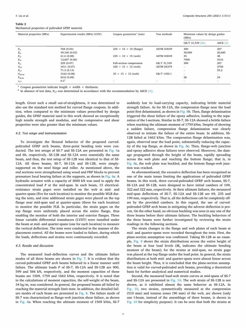
Table 2Mechanical properties of pultruded GFRP material.
Material properties (MPa) Experimental results (MPa) (COV) Coupon geometriesa (mm) Test methods Minimum values by design guides(MPa)
GB/T 31,539 [31] ASCE [1]
FLt 768 (0.04) 235 × 10 × 10 (flange) ASTM D3039 400 207ELt 49,160 (0.03) 30,000 20,685FTt 61.6 (0.08) 235 × 10 × 15 (web) ASTM D3039 45 48ETt 12,607 (0.06) 7000 5516FLc 229 (0.07) Full-section compression GB/T 31,539 300 207GLT 3411 (0.07) 320 × 15 × 15 (web) ASTM D5379 – 2758FLT 71.3 (0.13) – 55.2Gsh,int 3162 (0.08) 35 × 15 × 15 (web) GB/T 1450.1 – –
Fsh,int 69.8 (0.08) 28 24νLT 0.3b – – – –
a Coupon geometries indicate length × width × thickness.b In absence of test data, vLT was determined in accordance with the recommendation by ASCE [1].
T. Liu et al. Composite Structures 256 (2021) 113111
length. Given such a small out‐of‐straightness, it was determined toalso use the standard test method for curved flange coupons. In addi-tion, when compared to the minimum values prescribed by designguides, the GFRP material used in this work showed an exceptionallyhigh tensile strength and modulus, and the compressive and shearproperties were also greater than the minimum values.
4.2. Test setups and instrumentation
To investigate the flexural behavior of the proposed curved‐pultruded GFRP arch beams, three‐point bending tests were con-ducted. The test setups of SS‐7 and SS‐12A are presented in Fig. 6aand 6b, respectively. SS‐12B and SS‐12A were essentially the samebeam, and thus, the test setup of SS‐12B was identical to that of SS‐12A. All three beams, SS‐7, SS‐12A and SS‐12B, were simply‐supported on the steel hinge and roller. As mentioned above, theend sections were strengthened using wood and FRP blocks to preventpremature local bearing failure at the supports, as shown in Fig. 6c. Ahydraulic actuator with a capacity of 3000 kN was used to apply theconcentrated load P at the mid‐span. In each beam, 15 electrical‐resistance strain gages were installed on the web at mid‐ andquarter‐spans (five for each location) to monitor the possible WLB dur-ing the tests, and nine additional strain gages were placed on the topflange near mid‐span and at quarter‐spans (three for each location)to monitor the possible FLB. In particular, the strain gages on thetop flange were uniformly placed across the entire flange, thusenabling the monitor of both the interior and exterior flanges. Threelinear variable differential transducers (LVDT) were installed underthe beam at mid‐ and quarter‐spans (one for each location) to measurethe vertical deflection. The tests were conducted in the manner of dis-placement control. All the beams were loaded to failure, during whichthe loads, deflections and strains were continuously recorded.
4.3. Results and discussion
The measured load–deflection curves and the ultimate failuremodes of all three beams are shown in Fig. 7. It is evident that thecurved‐pultruded GFRP arch beams behaved in a linear manner untilfailure. The ultimate loads P of SS‐7, SS‐12A and SS‐12B are 900,599 and 566 kN, respectively, and the moment capacities of thosebeams are 1509, 1759 and 1662 kNm, respectively. It is noted thatin the calculations of moment capacities, the self‐weight of the beam,34 kg/m, was considered. In general, the proposed beams all failed byreaching the material strength limit state. In addition, the detailed fail-ure modes of each beam are presented in Fig. 8. The failure mode ofSS‐7 was characterized as flange‐web junction shear failure, as shownin Fig. 8a. When reaching the ultimate moment of 1509 kNm, SS‐7
7
suddenly lost its load‐carrying capacity, indicating brittle materialstrength failure. As for SS‐12A, the compression flange near the loadpoint first delaminated, as shown in Fig. 8b. Then, flange delaminationtriggered the shear failure of the epoxy adhesive, leading to the sepa-ration of the I‐sections. Similar to SS‐7, SS‐12A showed a brittle failurewhen reaching the ultimate moment of 1759 kNm. Despite of showinga sudden failure, compression flange delamination was clearlyobserved to initiate the failure of the entire beam. In addition, SS‐12B failed at 1662 kNm. The compression flange delamination was,again, observed near the load point, substantially reducing the capac-ity of the top flange, as shown in Fig. 8c. Then, flange‐web junctionand epoxy adhesive shear failures were observed. Moreover, the dam-age propagated through the height of the beam, rapidly spreadingacross the web plate and reaching the bottom flange; that is, inFig. 8c, the web plate was buckled, and the bottom flange‐web junc-tion was cracked.
As aforementioend, the excessive deflection has been recognized asone of the main issues limiting the applications of pultruded GFRPbeams. In this work, three curved‐pultruded GFRP arch beams, SS‐7,SS‐12A and SS‐12B, were designed to have initial cambers of 109,322 and 322 mm, respectively. At their ultimate failures, the measuredmid‐span deflections of SS‐7, SS‐12A and SS‐12B are 69, 235 and199 mm, respectively. That is, all the deflections cab be completely off-set by the provided cambers. In this regard, the use of curved‐pultruded GFRP arch beam in mitigating the adverse deflection is pro-ven. On the other hand, no obvious buckling was seen in any one of thethree beams before their ultimate failures. The buckling behaviors ofthe three beams were further investigated by reviewing the strainreadings in the following sections.
The strain changes in the flange and web plates of each beam atmid‐ and quarter‐spans were recorded throughout the tests. First, theplane‐section assumption was confirmed. Taking SS‐12B as an exam-ple, Fig. 9 shows the strain distributions across the entire height ofthe beam at four load levels (Mu indicates the ultimate bendingmoment of the beam); for the strains at mid‐span, no strain gagewas placed at the top flange under the load point. In general, the straindistributions at both mid‐ and quarter‐spans were almost linear acrossthe beam height. Thus, it is concluded that the plane‐section assump-tion is valid for curved‐pultruded arch beams, providing a theoreticalbasis for further analytical and numerical studies.
Second, the measured load‐web strain curves at mid‐spans of SS‐7and SS‐12A are presented in Fig. 10. The web strain of SS‐12B is notshown, as it exhibited almost the same behavior as SS‐12A. InFig. 10, two strains, symmetrically measured at the compression(510 mm) and tension zones (90 mm) of the web, are shown (onlyone I‐beam, instead of the assemblage of three beams, is shown inFig. 10 for simplicity purpose). It can be seen that both the strains at

Fig. 6. Three-point bending test setups.
T. Liu et al. Composite Structures 256 (2021) 113111
8
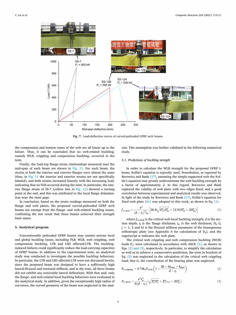
Fig. 7. Load-deflection curves of curved-pultruded GFRP arch beams.
T. Liu et al. Composite Structures 256 (2021) 113111
the compression and tension zones of the web are all linear up to thefailure. Thus, it can be concluded that no web‐related buckling,namely WLB, crippling and compression buckling, occurred in thetests.
Finally, the load‐top flange strain relationships measured near themid‐span of each beam are shown in Fig. 11. For each beam, thestrains at both the interior and exterior flanges were almost the same(thus, in Fig. 11 the interior and exterior strains are not specificallylabeled), and both strains increased linearly with the increasing load,indicating that no FLB occurred during the tests. In particular, the inte-rior flange strain of SS‐7 (yellow line in Fig. 11) showed a turningpoint at the end, and this was attributed to the local flange delamina-tion near the stain gage.
In conclusion, based on the strain readings measured on both theflange and web plates, the proposed curved‐pultruded GFRP archbeams are exempt from the flange‐ and web‐related buckling issues,confirming the test result that these beams achieved their strengthlimit states.
5. Analytical program
Conventionally pultruded GFRP beams may sustain serious localand global buckling issues, including FLB, WLB, web crippling, webcompression buckling, LTB and LSD affected‐LTB. The buckling‐induced failures could significantly reduce the load‐carrying capacitiesof GFRP beams. In addition to the experimental tests, an analyticalstudy was conducted to investigate the possible buckling behaviors.In particular, the LTB and LSD affected‐LTB were not discussed herein,since the proposed beam was designed to have a sufficiently highlateral‐flexural and torsional stiffness, and in the tests, all three beamsdid not exhibit any noticeable lateral deflections. With that said, onlythe flange‐ and web‐related local buckling behaviors were evaluated inthe analytical study. In addition, given the exceptionally high radius ofcurvature, the curved geometry of the beam was neglected in the anal-
9
ysis. This assumption was further validated in the following numericalstudy.
5.1. Predictions of buckling strength
In order to calculate the WLB strength for the proposed GFRP I‐beam, Kollár’s equation is typically used. Nonetheless, as reported byBorowicz and Bank [17], assuming the simply‐supported web the Kol-lár’s equation may greatly underestimate the web buckling strength bya factor of approximately 2. In this regard, Borowicz and Bankexplored the validity of web plate with two edges fixed, and a goodcorrelation between experimental and analytical results was observed.In light of the study by Borowicz and Bank [17], Kollár’s equation forfixed web plate [61] was adopted in this work, as shown in Eq. (1).
f cr;WLB ¼ π2
d� tf� �2tw 26:8
ffiffiffiffiffiffiffiffiffiffiffiffiffiffiffiDw
11Dw22
qþ 12:9 Dw
12 þ 2Dw66
� �h ið1Þ
where fcr,WLB is the critical web local buckling strength; d is the sec-tion depth; tf is the flange thickness; tw is the web thickness; Dij (i,j = 1, 2 and 6) is the flexural stiffness parameter of the homogenousorthotropic plate (see Appendix A for calculations of Dij), and thesuperscript w indicates the web plate.
The critical web crippling and web compression buckling (WCB)loads Pcr were calculated in accordance with ASCE [1], as shown inEqs. (2) and (3), respectively. In particular, to simplify the calculationas well as to achieve a conservative prediction, the term in brackets ofEq. (2) was neglected in the calculation of the critical web cripplingload; that is, the contribution of the bearing plate was neglected.
Pcr;crippling ¼ 0:7dtwFsh;int 1þ 2kþ 6tplate þ bplated� tf
� �ð2Þ
Pcr;WCB ¼ π2t3w6 d� tf� � ½ ffiffiffiffiffiffiffiffiffiffiffi
EwL E
wT
qþ Ew
T vLT þ 2GwLT � ð3Þ

Fig. 8. Failure modes of curved-pultruded GFRP arch beams.
Fig. 9. Flange and web strain distributions of SS-12B.
T. Liu et al. Composite Structures 256 (2021) 113111
10
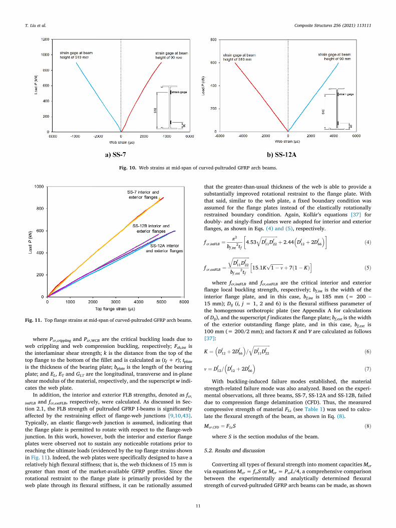
Fig. 10. Web strains at mid-span of curved-pultruded GFRP arch beams.
Fig. 11. Top flange strains at mid-span of curved-pultruded GFRP arch beams.
T. Liu et al. Composite Structures 256 (2021) 113111
where Pcr,crippling and Pcr,WCB are the critical buckling loads due toweb crippling and web compression buckling, respectively; Fsh,int isthe interlaminar shear strength; k is the distance from the top of thetop flange to the bottom of the fillet and is calculated as (tf + r); tplateis the thickness of the bearing plate; bplate is the length of the bearingplate; and EL, ET and GLT are the longitudinal, transverse and in‐planeshear modulus of the material, respectively, and the superscript w indi-cates the web plate.
In addition, the interior and exterior FLB strengths, denoted as fcr,intFLB and fcr,extFLB, respectively, were calculated. As discussed in Sec-tion 2.1, the FLB strength of pultruded GFRP I‐beams is significantlyaffected by the restraining effect of flange‐web junctions [9,10,43].Typically, an elastic flange‐web junction is assumed, indicating thatthe flange plate is permitted to rotate with respect to the flange‐webjunction. In this work, however, both the interior and exterior flangeplates were observed not to sustain any noticeable rotations prior toreaching the ultimate loads (evidenced by the top flange strains shownin Fig. 11). Indeed, the web plates were specifically designed to have arelatively high flexural stiffness; that is, the web thickness of 15 mm isgreater than most of the market‐available GFRP profiles. Since therotational restraint to the flange plate is primarily provided by theweb plate through its flexural stiffness, it can be rationally assumed
11
that the greater‐than‐usual thickness of the web is able to provide asubstantially improved rotational restraint to the flange plate. Withthat said, similar to the web plate, a fixed boundary condition wasassumed for the flange plates instead of the elastically rotationallyrestrained boundary condition. Again, Kollár’s equations [37] fordoubly‐ and singly‐fixed plates were adopted for interior and exteriorflanges, as shown in Eqs. (4) and (5), respectively.
f cr;intFLB ¼ π2
bf ;int2tf
4:53ffiffiffiffiffiffiffiffiffiffiffiffiffiffiffiDf
11Df22
qþ 2:44 Df
12 þ 2Df66
� � ð4Þ
f cr;extFLB ¼ffiffiffiffiffiffiffiffiffiffiffiffiffiffiffiDf
11Df22
qbf ;ext
2tf15:1K
ffiffiffiffiffiffiffiffiffiffiffi1� v
pþ 7 1� Kð Þ
h ið5Þ
where fcr,intFLB and fcr,extFLB are the critical interior and exteriorflange local buckling strength, respectively; bf,int is the width of theinterior flange plate, and in this case, bf,int is 185 mm (= 200 –
15 mm); Dij (i, j = 1, 2 and 6) is the flexural stiffness parameter ofthe homogenous orthotropic plate (see Appendix A for calculationsof Dij), and the superscript f indicates the flange plate; bf,ext is the widthof the exterior outstanding flange plate, and in this case, bf,ext is100 mm (= 200/2 mm); and factors K and v are calculated as follows[37]:
K ¼ Df12 þ 2Df
66
� �=
ffiffiffiffiffiffiffiffiffiffiffiffiffiffiffiDf
11Df22
qð6Þ
v ¼ Df12= Df
12 þ 2Df66
� �ð7Þ
With buckling‐induced failure modes established, the materialstrength‐related failure mode was also analyzed. Based on the experi-mental observations, all three beams, SS‐7, SS‐12A and SS‐12B, faileddue to compression flange delamination (CFD). Thus, the measuredcompressive strength of material FLc (see Table 1) was used to calcu-late the flexural strength of the beam, as shown in Eq. (8).
Mcr;CFD ¼ FLcS ð8Þwhere S is the section modulus of the beam.
5.2. Results and discussion
Converting all types of flexural strength into moment capacitiesMcr
via equationsMcr = fcrS or Mcr = PcrL/4, a comprehensive comparisonbetween the experimentally and analytically determined flexuralstrength of curved‐pultruded GFRP arch beams can be made, as shown
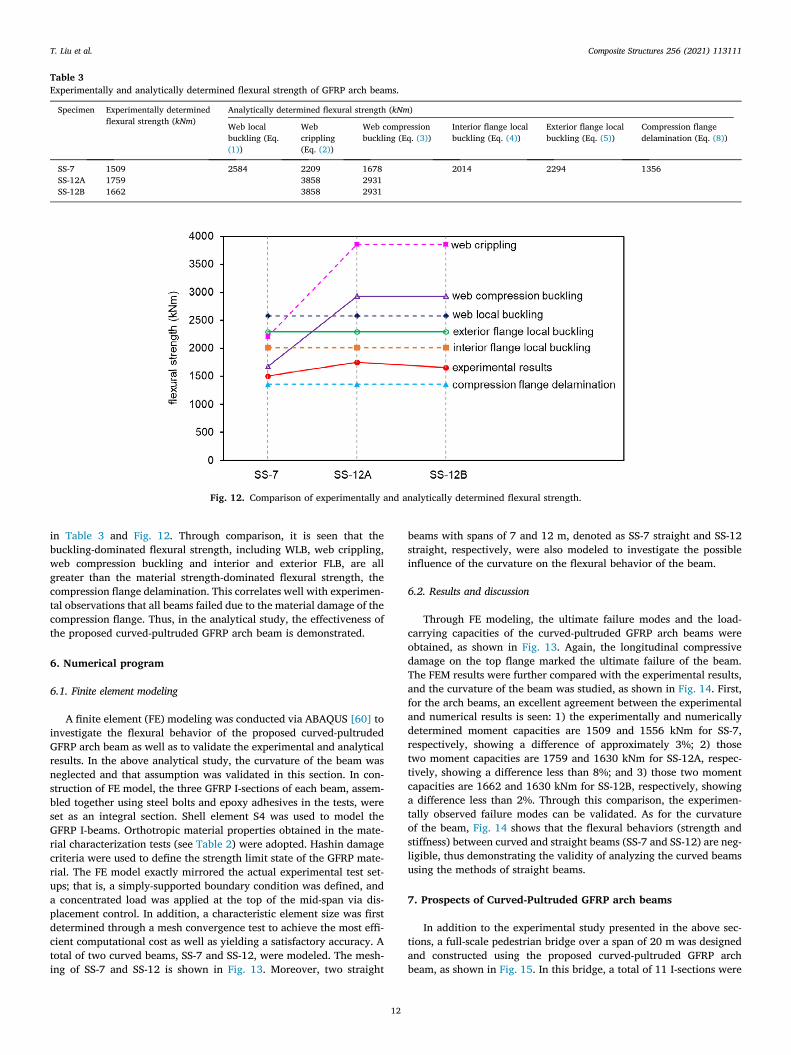
Table 3Experimentally and analytically determined flexural strength of GFRP arch beams.
Specimen Experimentally determinedflexural strength (kNm)
Analytically determined flexural strength (kNm)
Web localbuckling (Eq.(1))
Webcrippling(Eq. (2))
Web compressionbuckling (Eq. (3))
Interior flange localbuckling (Eq. (4))
Exterior flange localbuckling (Eq. (5))
Compression flangedelamination (Eq. (8))
SS-7 1509 2584 2209 1678 2014 2294 1356SS-12A 1759 3858 2931SS-12B 1662 3858 2931
Fig. 12. Comparison of experimentally and analytically determined flexural strength.
T. Liu et al. Composite Structures 256 (2021) 113111
in Table 3 and Fig. 12. Through comparison, it is seen that thebuckling‐dominated flexural strength, including WLB, web crippling,web compression buckling and interior and exterior FLB, are allgreater than the material strength‐dominated flexural strength, thecompression flange delamination. This correlates well with experimen-tal observations that all beams failed due to the material damage of thecompression flange. Thus, in the analytical study, the effectiveness ofthe proposed curved‐pultruded GFRP arch beam is demonstrated.
6. Numerical program
6.1. Finite element modeling
A finite element (FE) modeling was conducted via ABAQUS [60] toinvestigate the flexural behavior of the proposed curved‐pultrudedGFRP arch beam as well as to validate the experimental and analyticalresults. In the above analytical study, the curvature of the beam wasneglected and that assumption was validated in this section. In con-struction of FE model, the three GFRP I‐sections of each beam, assem-bled together using steel bolts and epoxy adhesives in the tests, wereset as an integral section. Shell element S4 was used to model theGFRP I‐beams. Orthotropic material properties obtained in the mate-rial characterization tests (see Table 2) were adopted. Hashin damagecriteria were used to define the strength limit state of the GFRP mate-rial. The FE model exactly mirrored the actual experimental test set-ups; that is, a simply‐supported boundary condition was defined, anda concentrated load was applied at the top of the mid‐span via dis-placement control. In addition, a characteristic element size was firstdetermined through a mesh convergence test to achieve the most effi-cient computational cost as well as yielding a satisfactory accuracy. Atotal of two curved beams, SS‐7 and SS‐12, were modeled. The mesh-ing of SS‐7 and SS‐12 is shown in Fig. 13. Moreover, two straight
12
beams with spans of 7 and 12 m, denoted as SS‐7 straight and SS‐12straight, respectively, were also modeled to investigate the possibleinfluence of the curvature on the flexural behavior of the beam.
6.2. Results and discussion
Through FE modeling, the ultimate failure modes and the load‐carrying capacities of the curved‐pultruded GFRP arch beams wereobtained, as shown in Fig. 13. Again, the longitudinal compressivedamage on the top flange marked the ultimate failure of the beam.The FEM results were further compared with the experimental results,and the curvature of the beam was studied, as shown in Fig. 14. First,for the arch beams, an excellent agreement between the experimentaland numerical results is seen: 1) the experimentally and numericallydetermined moment capacities are 1509 and 1556 kNm for SS‐7,respectively, showing a difference of approximately 3%; 2) thosetwo moment capacities are 1759 and 1630 kNm for SS‐12A, respec-tively, showing a difference less than 8%; and 3) those two momentcapacities are 1662 and 1630 kNm for SS‐12B, respectively, showinga difference less than 2%. Through this comparison, the experimen-tally observed failure modes can be validated. As for the curvatureof the beam, Fig. 14 shows that the flexural behaviors (strength andstiffness) between curved and straight beams (SS‐7 and SS‐12) are neg-ligible, thus demonstrating the validity of analyzing the curved beamsusing the methods of straight beams.
7. Prospects of Curved-Pultruded GFRP arch beams
In addition to the experimental study presented in the above sec-tions, a full‐scale pedestrian bridge over a span of 20 m was designedand constructed using the proposed curved‐pultruded GFRP archbeam, as shown in Fig. 15. In this bridge, a total of 11 I‐sections were

Fig. 13. Finite element models of I-beams with spans of 7 and 12 m (deformations amplified by a factor of 10 for illustration purpose).
Fig. 14. Comparison between experimental and numerical results.
T. Liu et al. Composite Structures 256 (2021) 113111
used. The total width of the flange was 2200 mm, and the height was600 mm. The identical beam assemblage scheme to SS‐7, SS‐12A andSS‐12B was adopted, as shown in Fig. 5b. The beam ends were fixed bya pair of tailor‐designed steel end‐supports. In addition, the steel end‐supports were connected through two steel tension members. Thus, infact, this bridge took the form of a beam‐string structure. An axial com-pression force was therefore provided to the beam when the bridgewas loaded, making it an arch‐like bridge.
This bridge was tested under the service limit state. Two Chinesedesign codes for municipal and highway bridges, CJJ69 [21] andJTG D60 [34], respectively, have prescribed the design pedestrianloads: 1) for municipal pedestrian bridges, the design load is 4.725kN/m2, resulting in a total load of 204 kN; and for highway pedestrianbridges, the design load is 3.5 kN/m2, resulting in a total load of 151kN. In addition, according to the Chinese design guide CECS [20] themaximum mid‐span deflection of the pultruded FRP beam with a span
13
over 5 m is L/250 (80 mm, in this case). In this work, the load was con-servatively taken as 7 kN/m2, and thus, a total load of 303 kN wasapplied on the bridge, which was realized through the lift trucksshown in Fig. 15a. At the design load, no damage was observed inthe GFRP beams, and the vertical deflection at mid‐span was measuredas 49 mm, which was less than the required maximum 80 mm, thussatisfying the deflection criterion. In addition, according to CJJ69[21], the minimum natural frequency of vibration for municipal pedes-trian bridges is 3 Hz. In this test, the proposed bridge showed a vibra-tion frequency of 20 Hz when the bridge was fully loaded, greater thanthe required minimum value. Thus, this GFRP pedestrian bridge is ableto satisfy the service requirement and provide an excellent load‐carrying capacity.
This 20‐m‐long pedestrian bridge, installed as a corridor betweentwo buildings as show in Fig. 15b, successfully showed the great pro-spects of the proposed curved‐pultruded GFRP arch beam. Through the
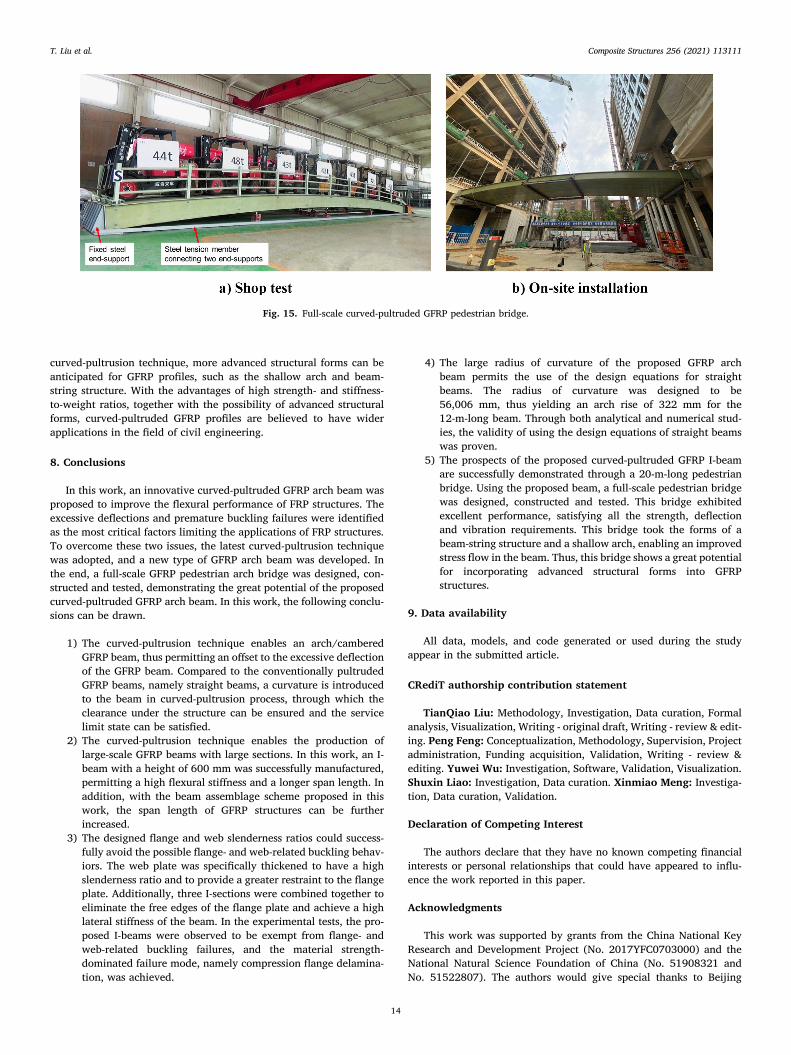
Fig. 15. Full-scale curved-pultruded GFRP pedestrian bridge.
T. Liu et al. Composite Structures 256 (2021) 113111
curved‐pultrusion technique, more advanced structural forms can beanticipated for GFRP profiles, such as the shallow arch and beam‐string structure. With the advantages of high strength‐ and stiffness‐to‐weight ratios, together with the possibility of advanced structuralforms, curved‐pultruded GFRP profiles are believed to have widerapplications in the field of civil engineering.
8. Conclusions
In this work, an innovative curved‐pultruded GFRP arch beam wasproposed to improve the flexural performance of FRP structures. Theexcessive deflections and premature buckling failures were identifiedas the most critical factors limiting the applications of FRP structures.To overcome these two issues, the latest curved‐pultrusion techniquewas adopted, and a new type of GFRP arch beam was developed. Inthe end, a full‐scale GFRP pedestrian arch bridge was designed, con-structed and tested, demonstrating the great potential of the proposedcurved‐pultruded GFRP arch beam. In this work, the following conclu-sions can be drawn.
1) The curved‐pultrusion technique enables an arch/camberedGFRP beam, thus permitting an offset to the excessive deflectionof the GFRP beam. Compared to the conventionally pultrudedGFRP beams, namely straight beams, a curvature is introducedto the beam in curved‐pultrusion process, through which theclearance under the structure can be ensured and the servicelimit state can be satisfied.
2) The curved‐pultrusion technique enables the production oflarge‐scale GFRP beams with large sections. In this work, an I‐beam with a height of 600 mm was successfully manufactured,permitting a high flexural stiffness and a longer span length. Inaddition, with the beam assemblage scheme proposed in thiswork, the span length of GFRP structures can be furtherincreased.
3) The designed flange and web slenderness ratios could success-fully avoid the possible flange‐ and web‐related buckling behav-iors. The web plate was specifically thickened to have a highslenderness ratio and to provide a greater restraint to the flangeplate. Additionally, three I‐sections were combined together toeliminate the free edges of the flange plate and achieve a highlateral stiffness of the beam. In the experimental tests, the pro-posed I‐beams were observed to be exempt from flange‐ andweb‐related buckling failures, and the material strength‐dominated failure mode, namely compression flange delamina-tion, was achieved.
14
4) The large radius of curvature of the proposed GFRP archbeam permits the use of the design equations for straightbeams. The radius of curvature was designed to be56,006 mm, thus yielding an arch rise of 322 mm for the12‐m‐long beam. Through both analytical and numerical stud-ies, the validity of using the design equations of straight beamswas proven.
5) The prospects of the proposed curved‐pultruded GFRP I‐beamare successfully demonstrated through a 20‐m‐long pedestrianbridge. Using the proposed beam, a full‐scale pedestrian bridgewas designed, constructed and tested. This bridge exhibitedexcellent performance, satisfying all the strength, deflectionand vibration requirements. This bridge took the forms of abeam‐string structure and a shallow arch, enabling an improvedstress flow in the beam. Thus, this bridge shows a great potentialfor incorporating advanced structural forms into GFRPstructures.
9. Data availability
All data, models, and code generated or used during the studyappear in the submitted article.
CRediT authorship contribution statement
TianQiao Liu: Methodology, Investigation, Data curation, Formalanalysis, Visualization, Writing ‐ original draft, Writing ‐ review & edit-ing. Peng Feng: Conceptualization, Methodology, Supervision, Projectadministration, Funding acquisition, Validation, Writing ‐ review &editing. Yuwei Wu: Investigation, Software, Validation, Visualization.Shuxin Liao: Investigation, Data curation. Xinmiao Meng: Investiga-tion, Data curation, Validation.
Declaration of Competing Interest
The authors declare that they have no known competing financialinterests or personal relationships that could have appeared to influ-ence the work reported in this paper.
Acknowledgments
This work was supported by grants from the China National KeyResearch and Development Project (No. 2017YFC0703000) and theNational Natural Science Foundation of China (No. 51908321 andNo. 51522807). The authors would give special thanks to Beijing

T. Liu et al. Composite Structures 256 (2021) 113111
Golden Bridge (Composites) Tech Co., LTD., for providing the GFRPmaterials. Their support is highly appreciated.
Appendix A
The flexural stiffness parameters of the orthotropic plate are calcu-lated as follows [12]:
D11 ¼ ELt3
12ð1� vLTvTLÞ ðA1Þ
D22 ¼ ETt3
12ð1� vLTvTLÞ ðA2Þ
D12 ¼ vLTD22 ðA3Þ
D66 ¼ GLTt3
12ðA4Þ
References
[1] American Society of Civil Engineers. Pre-Standard for Load and Resistance FactorDesign (LRFD) of Pultruded Fiber Reinforced Polymer (FRP) Structures. ASCE;2010.
[2] Ascione F, Feo L, Lamberti M, Minghini F, Tullini N. A closed-form equation for thelocal buckling moment of pultruded FRP I-beams in major-axis bending. Compos BEng 2016;97:292–9.
[3] Ascione L, Berardi VP, Giordano A, Spadea S. Local buckling behavior of FRP thin-walled beams: a mechanical model. Compos Struct 2013;98:111–20.
[4] Ascione L, Giordano A, Spadea S. Lateral buckling of pultruded FRP beams.Compos B Eng 2011;42(4):819–24.
[5] ASTM D3039/D3039M. Standard Test Method for Tensile Properties of PolymerMatrix Composite Materials. West Conshohocken, PA: ASTM International; 2017.
[6] ASTM D5379/D5379M.. Standard Test Method for Shear Properties of CompositeMaterials by the V-Notched Beam Method. West Conshohocken, PA: ASTMInternational; 2019.
[7] Bank LC. Properties of pultruded Fiber Reinforced Plastic structural members. In:Transportation Research Record, 1223. Washington, D.C: Transportation ResearchBoard; 1989. p. 117–24.
[8] Bank LC. Flexural and shear moduli of full-section fiber reinforced plastic (FRP)pultruded beams. J Test Eval 1989;17(1):40–5.
[9] Bank LC, Yin J. Failure of web-flange junction in postbuckled pultruded I-beams. JCompos Constr 1999;3(4):177–84.
[10] Bank LC, Gentry TR, Nadipelli M. Local buckling of pultruded FRP beams-analysisand design. J Reinf Plast Compos 1996;15(3):283–94.
[11] Bank LC, Yin J, Nadipelli M. Local buckling of pultruded beams-nonlinearity,anisotropy and inhomogeneity. Constr Build Mater 1995;9(6):325–31.
[12] Barbero EJ. Introduction to composite materials design (second edition). CRCPress; 2011.
[13] Barbero EJ, Raftoyiannis IG. Local buckling of FRP beams and columns. ASCE JMater Civil Eng 1993;5(3):339–55.
[14] Barbero EJ, Raftoyiannis IG. Lateral and distortional buckling of pultruded I-beams. Compos Struct 1994;27(3):261–8.
[15] Barbero EJ, Fu SH, Raftoyiannis I. Ultimate bending strength of composite beams.ASCE J Mater Civ Eng 1991;3(4):292–306.
[16] Borowicz DT, Bank LC. Behavior of pultruded fiber-reinforced polymer beamssubjected to concentrated loads in the plane of the web. J Compos Constr 2011;15(2):229–38.
[17] Borowicz DT, Bank LC. Web buckling in pultruded fiber-reinforced polymer deepbeams subjected to concentrated loads. J Compos Constr 2014;18(3):A4013014.
[18] Britnell D, Tucker N, Smith G, Wong SS. Bent pultrusion—a method for themanufacture of pultrudate with controlled variation in curvature. J Mater ProcessTechnol 2003;138(1–3):311–5.
[19] Brooks RJ, Turvey GJ. Lateral buckling of pultruded GRP I-section cantilevers.Compos Struct 1995;32(1):203–15.
[20] China Association for Engineering Construction Standardization. Technicalspecification for pultruded fiber reinforced polymer composites structure.T/CECS 692-2020. (In Chinese).
[21] CJJ69. Technical Specifications of Urban Pedestrian Overcrossing and Underpass.Ministry of Housing and Urban-Rural Development of the P. R. China 1995. (InChinese).
[22] Correia JR, Branco FA, Ferreira JG. Flexural behaviour of GFRP–concrete hybridbeams with interconnection slip. Compos Struct 2007;77(1):66–78.
[23] Correia JR, Branco FA, Silva NMF, Camotim D, Silvestre N. First-order, bucklingand post-buckling behaviour of GFRP pultruded beams. Part 1: Experimentalstudy. Comput Struct 2011;89(21):2052–64.
[24] Davalos JF, Qiao P. Analytical and experimental study of lateral and distortionalbuckling of FRP wide-flange beams. ASCE J Compos Constr 1997;1(4):150–9.
15
[25] Davalos JF, Qiao P, Salim HA. Flexural-torsional buckling of pultruded fiberreinforced plastic composite I-beams: Experimental and analytical evaluations.Compos Struct 1997;38(1):241–50.
[26] Estep DD, GangaRao HV, Dittenber DB, Qureshi MA. Response of pultruded glasscomposite box beams under bending and shear. Compos B Eng 2016;88:150–61.
[27] Ascione L, Caron JF, Godonou P, Van IJselmuijden K, Knippers J, Mottram T, et al.Prospect for new guidance in the design of FRP (EUR27666). Publications Office ofthe European Union; 2016.
[28] Feng P, Wang J, Wang Y, Loughery D, Niu D. Effects of corrosive environments onproperties of pultruded GFRP plates. Compos B Eng 2014;67:427–33.
[29] Feng P, Wang J, Tian Y, Loughery D, Wang Y. Mechanical behavior and design ofFRP structural members at high and low service temperatures. ASCE J ComposConstr 2016;20(5):4016021.
[30] GB/T 1450.1. Fibre-reinforced plastic composites – Determination of interlaminarshear strength. China Association for Engineering Construction Standardization(CECS) 2005. (In Chinese).
[31] GB/T 31539. Pultruded fiber reinforced polymer composites structural profiles.China Association for Engineering Construction Standardization (CECS) 2015.(In Chinese).
[32] Insausti A, Puente I, Azkune M. Interaction between local and lateral buckling onpultruded I-beams. ASCE J Compos Constr 2009;13(4):315–24.
[33] ISO 1172. Textile-glass-reinforced plastics — Prepregs, moulding compounds andlaminates — Determination of the textile-glass and mineral-filler content —Calcination methods. ISO Technical Committee: ISO/TC 61/SC 13 Composites andreinforcement fibres 1996.
[34] JTG D60. General code for design of highway bridges and culverts. Ministry ofTransport of the P. R. China 2004. (In Chinese).
[35] Kabir MZ, Sherbourne AN. Lateral-torsional buckling of post-local buckled fibrouscomposite beams. J Eng Mech 1998;124(7):754–64.
[36] Kennedy KC, Kusy RP. UV-cured pultrusion processing of glass-reinforced polymercomposites. J Vinyl Add Tech 1995;1(3):182–6.
[37] Kollár LP. Local buckling of fiber reinforced plastic composite structural memberswith open and closed cross sections. ASCE J Struct Eng 2003;129(11):1503–13.
[38] Laudiero F, Minghini F, Tullini N. Postbuckling failure analysis of pultruded FRPbeams under uniform bending. Compos B Eng 2013;54:431–8.
[39] Lin ZM, Polyzois D, Shah A. Stability of thin-walled pultruded structural membersby the finite element method. Thin-Walled Struct 1996;24(1):1–18.
[40] Liu W, Feng P, Huang J. Bilinear softening model and double K fracture criterionfor quasi-brittle fracture of pultruded FRP composites. Compos Struct2017;160:1119–25.
[41] Liu T, Harries KA. Flange local buckling of pultruded GFRP box beams. ComposStruct 2018;189:463–72.
[42] Liu T, Vieira JD, Harries KA. Lateral torsional buckling and section distortion ofpultruded GFRP I-sections subject to flexure. Compos Struct 2019;225:111151.
[43] Liu T, Vieira JD, Harries KA. Predicting flange local buckling capacity of pultrudedGFRP I-sections subject to flexure. J Compos Constr 2020;24(4):04020025.
[44] Liu T, Yang JQ, Feng P, Harries KA. Determining rotational stiffness of flange-webjunction of pultruded GFRP I-sections. Compos Struct 2020;236:111843.
[45] Liu T, Liu X, Feng P. A comprehensive review on mechanical properties ofpultruded FRP composites subjected to long-term environmental effects. Compos BEng 2020;191:107958.
[46] Liu T, Feng P, Lu X, Yang JQ, Wu Y. Flexural Behavior of Novel Hybrid MulticellGFRP-Concrete Beam. Compos Struct 2020;250:112606.
[47] Mittelstedt C. Buckling and Postbuckling of Thin-Walled Composite LaminatedBeams – A Review of Engineering Analysis Method. Applied Mechanics Reviews2020;72(2):020802.
[48] Mosallam AS, Bank LC. Short-term behavior of pultruded fiber-reinforced plasticframe. J Struct Eng 1992;118(7):1937–54.
[49] Mottram JT. Lateral-torsional buckling of a pultruded I-beam. Composites 1992;23(2):81–92.
[50] Nagaraj V, GangaRao HV. Static behavior of pultruded GFRP beams. J ComposConstr 1997;1(3):120–9.
[51] Nguyen TT, Chan TM, Mottram JT. Lateral-torsional buckling resistance by testingfor pultruded FRP beams under different loading and displacement boundaryconditions. Compos B Eng 2014;60:306–18.
[52] Pandey MD, Kabir MZ, Sherbourne AN. Flexural-torsional stability of thin-walledcomposite I-section beams. Compos Eng 1995;5(3):321–42.
[53] Pecce M, Cosenza E. Local buckling curves for the design of FRP profiles. Thin-Walled Struct 2000;37(3):207–22.
[54] Qiao P, Zou G. Local buckling of composite fiber-reinforced plastic wide-flangesections. ASCE J Struct Eng 2003;129(1):125–9.
[55] Qiao P, Davalos JF, Wang J. Local buckling of composite FRP shapes by discreteplate analysis. ASCE J Struct Eng 2001;127(3):245–55.
[56] Qiao P, Zou G, Davalos JF. Flexural–torsional buckling of fiber-reinforced plasticcomposite cantilever I-beams. Compos Struct 2003;60(2):205–17.
[57] Roberts TM, Al-Ubaidi H. Flexural and torsional properties of pultruded fiberreinforced plastic I-profiles. J Compos Constr 2002;6(1):28–34.
[58] Safonov AA, Carlone P, Akhatov I. Mathematical simulation of pultrusionprocesses: A review. Compos Struct 2018;184:153–77.
[59] Sapkás Á, Kollár LP. Lateral-torsional buckling of composite beams. Int J SolidsStruct 2002;39(11):2939–63.
[60] Simulia DS. Abaqus 6.14 documentation. Providence, Rhode Island. US 2014.[61] Tarján G, Sapkás Á, Kollár LP. Stability analysis of long composite plates with
restrained edges subjected to shear and linearly varying loads. J Reinf PlastCompos 2010;29(9):1386–98.
T. Liu et al. Composite Structures 256 (2021) 113111
[62] Tena I, Sarrionandia M, Torre J, Aurrekoetxea J. The effect of process parameterson ultraviolet cured out of die bent pultrusion process. Compos B Eng2016;89:9–17.
[63] Thomas Technik and Innovation. Radius Pultrusion. Retrieved from: www.thomas-technik.de/en/pultrusion/process/radius-pultrusion (Aug 20, 2020).
[64] Tonatto ML, Tita V, Amico SC. Composite spirals and rings under flexuralloading: Experimental and numerical analysis. J Compos Mater 2020;54(20):2697–705.
[65] Turvey GJ. Lateral buckling tests on rectangular cross-section pultruded GRPcantilever beams. Compos B Eng 1996;27(1):35–42.
[66] Turvey GJ. Effects of load position on the lateral buckling response of pultrudedGRP cantilevers—comparisons between theory and experiment. Compos Struct1996;35(1):33–47.
[67] Turvey GJ. Testing and analysis of pultruded GFRP continuous beamsfor the deflection serviceability limit state. Compos Struct 2016;141:213–20.
[68] Turvey GJ, Zhang Y. Characterisation of the rotational stiffness and strength ofweb-flange junctions of pultruded GRP WF-sections via web bending tests. ComposA Appl Sci Manuf 2006;37(2):152–64.
[69] Turvey GJ, Zhang YS. Flexural moduli and end connection stiffnesses ofsymmetrically loaded GFRP beams for limit state serviceability design analysis.Compos Struct 2018;202:1164–75.
[70] Vedernikov A, Safonov A, Tucci F, Carlone P, Akhatov I. Pultruded materials andstructures: A review. J Compos Mater 2020;002199832092289.
16
[71] Vieira JD, Liu T, Harries KA. Flexural stability of pultruded glass fibre-reinforcedpolymer I-sections. Proceedings of the Institution of Civil Engineers – Structuresand Buildings 2018;171(11):855–66.
[72] Yang JQ, Feng P. Analysis-oriented models for FRP-confined concrete: 3Dinterpretation and general methodology. Eng Struct 2020;216:110749.
[73] Zeinali E, Nazari A, Showkati H. Experimental-numerical study on lateral-torsionalbuckling of PFRP beams under pure bending. Compos Struct 2020;237:111925.
[74] Zou X, Feng P, Wang J. Perforated FRP ribs for shear connecting of FRP-concretehybrid beams/decks. Compos Struct 2016;152:267–76.
[75] Zou X, Feng P, Wang J. Bolted shear connection of FRP-concrete hybrid beams.ASCE J Compos Constr 2018;22(3):4018012.
[76] Zou X, Feng P, Bao Y, Wang J, Xin H. Experimental and analytical studies on shearbehaviors of FRP-concrete composite section. Eng Struct 2020;215:110749.
[77] Zuo Y, Mosallam A, Xin H, Liu Y, He J. Flexural performance of a hybrid GFRP-concrete bridge deck with composite T-shaped perforated rib connectors. ComposStruct 2018;194:263–78.
[78] Xin H, Mosallam A, Liu Y, Wang C, Zhang Y. Impact of hygrothermal aging onrotational behavior of web-flange junctions of structural pultruded compositemembers for bridge applications. Compos B Eng 2017;110:279–97.
[79] Mosallam A, Feo L, Elsadek A, Pul S, Penna R. Structural evaluation of axial androtational flexibility and strength of web-flange junctions of open-web pultrudedcomposites. Compos B Eng 2014;66:311–27.
[80] Wadee A, Gardner L. Cellular buckling from mode interaction in I-beams underuniform bending. Proc. R. Soc. A 2012;468:245–68.