Embed Size (px)
Citation preview

Ž .Computers in Industry 41 2000 213–238www.elsevier.nlrlocatercompind
Developing a computer shop floor control model for a CIMsystem — using object modeling technique
C. Ou-Yang ), T.Y. Guan, J.S. LinDepartment of Industrial Management, National Taiwan UniÕersity of Science and Technology, 43, Keelung Road, Section 4,
Taipei, 106 Taiwan
Received 12 September 1997; accepted 30 August 1999
Abstract
In this paper, an analyzing process for building a shop floor controller model is addressed by using Object ModelŽ .Technique OMT . The major objective of the proposed shop floor controller model is to bridge the gaps between the
production planning level and manufacturing level in a CIM environment such that production orders can be properly carriedout by the shop floor equipment. In addition, shop floor dynamic conditions also can be fed back to the planning level. There
Ž .are three modules in this model. 1 Planning and Scheduling Module takes charge of transferring production orders intoŽ .detailed manufacturing tasks. 2 Dispatching and Coordination Module issues production commands to the controllers ofŽ .proper production equipment. 3 Data Monitoring and Analysis Module collects and analyzes shop floor data in order to
identify the shop floor dynamic conditions. An implementation environment about the proposed model is also presented inthe final part of this paper. q 2000 Elsevier Science B.V. All rights reserved.
Keywords: Object Modeling Technique; Shop floor controller model; CIM
1. Introduction
In the current business environment, quality andvariety are two of the major factors required to keepproducts in a competitive market. Due to the increaseof labor cost, automated production systems such as
Ž .flexible manufacturing cells FMC , flexible manu-Ž .facturing systems FMS or computer integrated
Ž .manufacturing systems CIM are used by manyindustries to produce a range of quality products.
) Corresponding author. Tel.: q886-2-7376342; fax: q886-2-7376344.
Ž .E-mail address: [email protected] C. Ou-Yang .
Ž .Based on the concepts of group technology GT ,parts with similar shapes, dimensions and tolerancemight require similar fabrication processes. There-fore, production equipment can be grouped as a cellin order to simplify the production flow and schedul-ing problems and to improve the production effi-
w xciency 1 . An FMC is composed of a set of opera-tion stations andror material handling stations toproduce a family of parts. Improving the manufactur-ing functions within an individual work cell such asthe coordination of a CNC machine and a robot has
w xbeen addressed by many researchers 2,3 . However,many production activities, such as moving partsfrom one cell to another or down loading a NCprogram from a computer aided manufacturing
0166-3615r00r$ - see front matter q 2000 Elsevier Science B.V. All rights reserved.Ž .PII: S0166-3615 99 00057-3

( )C. Ou-Yang et al.rComputers in Industry 41 2000 213–238214
Ž .CAM station to a machine controller, still requiredhuman workers to be involved. In other words, eachautomatic manufacturing cell is an automation is-land.
Integrating several automation islands as an inte-grated manufacturing system was attracted attentionsfrom many researchers in recent years. One of themajor objectives of CIM is to integrate the materialflow and information flow in a shop as a whole suchthat human intervention can be reduced to the mini-mum level during fabrication processes. In general,most of the material flow activities take place in thefactory level. For example, moving raw materialsfrom an automatic storage and retrieval systemŽ . Ž .ASrRS to an automatic guided vehicle AGV or
Ž .transferring work-in-process WIP from an AGV toa robot. The major integration issue in material flowis how to transfer different kinds of materials amongvarious types of workstations and material handlingstations.
When WIPs are transferred in a production line, itis necessary to transmit related information from oneworkstation to another workstation simultaneously.Basically, there are several kinds of informationrequired at the shop floor level during a productionprocess. They are:
i. Machine control commands such as CNC codes,robot control commands and AGV moving com-mands;ii. product-related messages such as the codes forraw materials, WIP and finished products;iii. process-related messages such as machinestarting commands, operation finishing com-mands, machine status messages . . . etc.;iv. management-related messages such as the qual-ity and quatities of finished products and theirfinishing time.
In addition to the information required at the shopfloor level, there are other data required at the upper
Ž .level or the production planning level such as theŽ .information about product design CADrCAM ,
process planning and manufacturing resource plan-Ž .ning MRP . Basically, the information in these two
levels has closed relationships. For example, thescheduling data from a MRP module along with theNC codes or equipment control commands from aCAM module need to be transmitted to proper ma-
chines at the proper time. Also, the process finishingcommands or machine error messages from eachworkstation also need to feedback to the schedulingand material resource modules for data updating.Many researchers focused on integrating data withineach level. For example, applying feature-based ap-proach to integrate CADrCAM and process plan-
w xning 4 or applying knowledge-based approach tow xmanage the interface between CAD and MRP 5 .
However, there still exists a gap between these twolevels. The primary functions required to bridge the
Ž .gaps are: i properly allocate manufacturing re-Ž .sources, ii issue production orders to individual
Ž .equipment, iii supervise shop floor operations andŽ . w xiv coordinate workstation activities 6 . In CIM
w xmodels proposed by many researchers 6–8 , thesefunctions are fulfilled by shop floor control systems.
In this paper, a shop floor control model is pro-posed by applying Object Modeling TechniqueŽ . w xOMT 9 . This model is applied in the CIM systemcurrently developed in Automation and Control Cen-ter at National Taiwan University of Science and
Ž .Technology NTUST . The proposed framework andits modeling process also can be viewed as a refer-ence for developing a shop floor controller in othersystems.
In the following sections of this paper, a briefreview about the works in shop floor control systemswill be presented first. Then, the research issuesabout modeling a shop floor controller and an intro-duction about OMT will be given. The processes ofdeveloping a shop floor controller by using OMTwill be focused after an introduction about the hard-ware of the CIM system. A case about the applica-tion of the proposed framework and its implementa-tion environment will be given in the final part ofthis paper.
2. Shop floor controlrrrrrcell control models
In traditional systems, the tasks of shop floorcontrol and cell control are performed by pro-
Ž .grammable logic controllers PLC . By using ladderlogic or sequential functional control languages, PLCsequentially supervise the equipment in the cell.However, due to the lack of certain advanced func-tions such as decision making within a cell or manu-facturing data transfer among different equipment,

( )C. Ou-Yang et al.rComputers in Industry 41 2000 213–238 215
PLCs is not suitable in controlling a modern manu-w xfacturing system in a CIM system 10 .
The rapid progress of computer technologiesbrings shop floor control functions into a new area.Many advanced functions have been introduced asthe results of improving computing power. Thesefunctions include real time scheduling, networking
w xand cell coordination 11 . Since the functions ofshop floor control become more complex than be-fore, several control architecture and models wereproposed. One of the most famous models is
ŽNISTrAMRF National Institute of Standard andTechnologyrAdvanced Manufacturing Research Fa-
.cility proposed by National Bureau of Standards. Byapplying hierarchical control architecture, it is com-posed of five-level hierarchy: facility, shop, cell,workstation and equipment. Each level has its spe-cific but related functions. The business functionssuch as order priority, cost accounting, aggregateplanning are executed in the facility level. Shop levelis responsible for coordinating production tasks in-cluding resource allocation and task assignment. Celllevel is subject to sequence similar parts in batchjobs and supervises supporting tasks such as materialhandling and transportation. For each batch of parts,a set of related machines are grouped virtually as acell under a software structure. This virtual cellconcept improves the production efficiency by usingthe same set of tools and similar setups. The work-station level is responsible for generating productionschedule of workstations. In AMRF, a workstationgenerally consists of a robot, a fabrication station, amaterial storage buffer and a control computer. Fi-nally, equipment level is responsible for monitoring
w xthe execution of production tasks 7,8,12 .Odjima and Torii developed a functional cell
control model, which is similar to AMRF model, in aw xprinted wiring board assembly environment 13 .
They applied functional matrices in the designing ofa cell controller. However, the major functions ofthis model are collecting machine status data andsending production control commands. There is noadvanced function such as scheduling or fault toler-ance in this model.
Another hierarchical model developed by CAM-IŽ .Computer Aided Manufacturing-International is fo-cused on decision making for the manufacturingsystem. There are four distinct levels of control in
Žthis AFMCS Advanced Factory Management and.Control Systems model: factory level, job shop
level, work center level and resource level. A deci-Žsion-making module MADEMA MAnufacturing
.DEcision MAking was developed at the work centerlevel. It applies a decision matrix on the assignmentof manufacturing resources such as machine tools ormaterial handling equipment to production tasksw x8,14 .
The other hierarchical model proposed by Poyserhas four distinct levels: business system level, arealevel, cell level and equipment level. Shop floorcontrollers have been applied in the area level andcell level to bridge the gap between business systemlevel and equipment level. The major functions of ashop floor controller are planningrscheduling, su-pervision, resource management and workstation
w xcontrol 6 . With these functions, a shop floor con-troller not only can control a manufacturing systembut also has capabilities to manage several lowerlevel cell controllers.
Ž .The CIM-OSA Open System Architecture de-Žveloped by ESPRIT European Strategic Program for
Research and Development in Information Technol-.ogy program plans to offer a generic CIM architec-
ture for industries in Europe. Basically, it containsŽ .two environments: i enterprise engineering en-
vironment involving a reference architecture andŽ .resources for building an enterprise model; ii
enterprise operation environment containing an im-plementation model and resources for executing tasksdefined in the enterprise operation. A language andbuilding blocks for modeling CIM systems are also
w xdefined 15,19 .The role played by a cell controller is similar to
the works done by a slave. That is, a cell controlleraccepts manufacturing orders from its upper level,issues related production commands to its lowerlevel and reports finishing information to its upperlevel. In O’Grady’s approach, several intelligencefunctions, such as cell scheduling, job dispatchingand coordination, have been added into a cell con-
w xtroller 16 . The slavermaster relationships betweena cell controller and its supervisor, shop controller,are loosened. This kind of hierarchical model is
w xcalled modified hierarchical model 17 .The IDEF method is a popular tool used in model-
ing and analyzing manufacturing systems. Among

( )C. Ou-Yang et al.rComputers in Industry 41 2000 213–238216
Žthe series of IDEF methods, IDEF0 functional mod-.eling has been used by several researchers in ana-
w xlyzing various manufacturing systems 20 . In addi-tion, a few works have linked IDEF0 with other toolssuch as Petri net in modeling manufacturing systemsw x21,22 .
Several researchers have applied object-orientedconcepts in modeling manufacturing systems. Forinstance, Mize et al. have developed an object-ori-
Ž .ented modeling OOM environment which appliedŽ .object-oriented programming OOP and related
w xtechnologies to model a CIM system 23 . Severaladvantages and limitations of using OOP technolo-gies in CIM modeling also were addressed in thiswork. In addition, an object-oriented software systemfor discrete event simulation has been developed andimplemented in a manufacturing system including
w xshop floor control activities 24,25 . The modelingefforts in this work were focused on defining theclass objects in a manufacturing system in order tobe used by an object-oriented based simulation envi-ronment. Another work was addressed on applyingOOP methodology in an auction-based shop floordispatching system. The object oriented concepts areused in modeling the main entities, such as part,machine, factory control and event management, usedin the dispatching system. Each entity has embeddedfew attributes and methods used in the bidding pro-
w xcess 26 .Although various works related to the modeling
of shop floor controllers were presented, a systematicanalyzing process for building a shop floor controllerwas not addressed by those researchers. OMT ap-proach can be used to support this issue. Basically,
Ž .OMT focuses on i identifying objects and theirŽ .related properties from the application domain, iiŽ .building the relationships among objects, and iii
describing the data transformation within the system.It can be found that this approach provides an ana-lyzing process in modeling a system from its infor-mation, functional and process points of view but notits resource view. Therefore, in this paper, a shopfloor control model using OMT is presented.
3. Object modeling technique
This section outlines the basic principles of OMTand its applications to manufacturing systems. The
major concept of OMT is that it applies three kindsof models to describe a system. They are the objectmodel, the dynamic model and the functional model.The object model describes the major structure ofobjects in a system including the identities, attributesand operations of individual object as well as therelationships among each object. It is the majorframework of an OMT model and the basis ofdynamic and functional models. The dynamic modeldescribes the sequence of operations occurred in thesystem. Operations are triggered by the values ofattributes in each object. Finally, the functional modeldescribes the data flow of the system. Each functionis invoked by operations in the object model andactions in dynamic model.
All of the three models are represented graphi-cally in OMT model. In object diagrams, a class isrepresented as a rectangular box with its name,attributes and operations. An instance is representedas a rounded box with its class name, its own nameand the values of its attributes. For example, Fig. 1-1shows a ‘‘robot’’ class and one specific instancerobot ‘‘R001’’.
The concepts of inheritance and generalizationalso can be described in the object model. In OMTmethod, the notation of generalization is a trianglelinking the class and its subclasses. For example, inFig. 1-2, robot is the super class of SCARA robotand jointed-arm robot. The class of SCARA robotand jointed-arm robot not only inherits the featuresof robot class, but also has their own features.
Aggregation describes the ‘‘a-part-of’’ relation-ships between a class and its components. The nota-tion of aggregation is a diamond linking relatedclasses. Fig. 1-3 shows the aggregation relationshipof the class ‘‘jointed-arm robot’’ and its three com-ponents: base, lower arm and upper arm.
Association describes the relationship among twoclasses. For example, if a robot loads parts into a NCmachine, then the class robot might associate withthe class NC machine in terms of loading parts. Inaddition, association also can represent one to manyor many to many relationships. A solid ball is usedas a multiplicity symbol. For example, in a workcell, a robot may load parts into many NC machinesŽ .Fig. 1-4 .
The major concepts in dynamic model are eventsand states. Basically, a state represents a set of

( )C. Ou-Yang et al.rComputers in Industry 41 2000 213–238 217
Ž . Ž . Ž .Fig. 1. Various representation methods in object diagram: 1 the object diagram of ‘‘robot’’ class; 2 the generalization relationship; 3Ž .the aggregation relationship; 4 one to many association.

( )C. Ou-Yang et al.rComputers in Industry 41 2000 213–238218
Ž . Ž .Fig. 2. 1 The simplified state diagram of jointed-arm robot; 2the data flow diagram of a simplified robot control system.
attribute values of an object. The objects in a systemwill stimulate each other and cause a series ofchanges in their states. Each stimulus from oneobject to another is called an event. For a givenclass, the series of state transitions can be repre-sented as a state diagram. The dynamic model iscomposed of a group of state diagrams. Each statediagram describes the activities of one class. All ofthe state diagrams in a dynamic model can be exe-cuted concurrently through shared events. For exam-ple, Fig. 2-1 is a simplified state diagram for theclass ‘‘jointed-arm robot’’.
The functional model is composed of several dataŽ .flow diagrams DFD . A data flow diagram contains
four kinds of components. A process, which isdrawn as an ellipse, describes the way to transformdata. Basically, each process is implemented as a
method of an operation on an object class. A dataflow links two objects or processes. It represents anintermediate data value within computation. An ac-tor is an active object that conducts the data flow bygenerating or receiving data values. The notation ofan actor is a rectangle to show that it is an object.Finally, a data store, which is drawn as two parallellines with its name, is used to store data for thesystem. The stored data can be added, modified,retrieved and deleted through data flow. Fig. 2-2shows the DFD of a simplified robot control system.
4. Facilities of the CIM system
Fig. 3 shows the layout of the CIM system inAutomation and Control Center at NTUST. ASrRSis used to store raw materials, WIP and finishedparts. There are two fabrication machines: a Lead-well LTC-10P CNC lathe for producing rotationalparts and a Leadwell FMC-0P CNC machining cen-ter for manufacturing non-rotational parts. The ma-chined parts are inspected in a Mitutoyo KN807
Ž .coordinate measuring machine CMM . An ABBIRB2000 jointed-arm robot is used to load and un-load parts for CNC lathe and CMM. The CNCmachining center has its own loading and unloadingfacility. An AGV takes charge of transferring mostof parts ranged from raw materials to finished partsto the loading and unloading stations of individual
Ž .machine. The flexible assembly system FAS in-cluding five pneumatic Cartesian coordinate robotsare used for the final parts assembly.
Fig. 4 shows the control architecture of the CIMŽ .system. A manufacturing resource planning MRP
Fig. 3. The layout of the CIM system.

( )C. Ou-Yang et al.rComputers in Industry 41 2000 213–238 219
Fig. 4. The control architecture of the CIM system.
software is installed in the top-level computer. Theproduction orders from MRP are sent to the shopfloor controller connecting several machine con-trollers and PLCs. Currently, the communications inthe shop floor level are based on RS-232.
5. The proposed shop floor controller model
From the previous introduction, it can be foundthat the major role played by the shop floor con-troller in this CIM system is to link the manufactur-ing planning system with shopfloor level machinecontrollers. Three problems need to be addressedwhile building the bridge between these two levels:
1. How to transfer the production plans in the plan-ning level to the production activities in theshopfloor level?
2. How to assure the production plans can be carriedout as planned?
3. How to react to the dynamic situations occurredon the shopfloor?
In addition, the proposed model not only focuseson the current status of the CIM system, but alsoconsiders the possible extension of the system. Forexample, one AGV or a few CNC machines mightbe included into the system in the near future suchthat certain functions can be performed by more thanone machine.
In order to answer the above questions, threemodules are developed in the proposed model. One
Ž .is Planning and Scheduling Module PSM . Its majortasks are:
1. obtain production orders including order number,part number, product quantity and due date fromthe planning level,
2. examine production and material resources,3. decompose production orders based on the rout-
ing information of parts,4. determine proper machines, and5. issue manufacturing tasks.
The manufacturing tasks are sent to DispatchingŽ .and Coordination Module DCM . For each task, this
module will assure the status of the assigned equip-ment and its related resources as well as issueproduction commands to proper equipment at thepredetermined time. In addition, this module alsohandles abnormal conditions such as machinebreakdown. In this situation, DCM will identify theproblems, arrange a proper replacement and reportthe status to PSM to update production schedule.
The final module is Data Monitoring and AnalysisŽ .Module DMAM . Its major functions are to monitor
shop floor machine status and to collect and analyzeshop floor data for certain production managementpurposes.
5.1. The object model
The first step in constructing an object model is toidentify all of the proper object classes includingphysical and conceptual entities about the shop floorcontrol system. Then, those classes that are notsuitable for the model, such as redundant classes,irrelevant classes or vague classes, are combined,removed or refined. The following three categoriesof classes are obtained through the above processes.
1. Controllers in the shop floor:i. shop floor controllerii. cell controlleriii. equipment controller.
2. Shop floor controller modules:i. PSMii. DCMiii. DMAM.

( )C. Ou-Yang et al.rComputers in Industry 41 2000 213–238220
3. Cell controller related classes:i. work ordersii. product routingiii. materialsiv. scheduling rulesv. manufacturing equipmentvi. data collection equipmentvii. toolsviii. manufacturing commands
After identifying all of the required classes, thenext steps are to find the associations or relationshipsamong classes and to identify the attributes of eachclass. Basically, the major function of a shop floorcontroller is to fulfill the orders from planning levelby utilizing limited resources such as materials, ma-chines and tools. As to the associations of the threemodules in the shop floor controller, the manufactur-ing orders including the production sequence andstarting time of individual product are determined byPSM and sent to DCM. The major functions of DCMare to check the equipment status and issue manufac-turing commands to proper equipment controllers.
DMAM collects ongoing manufacturing informationand reports abnormal conditions to DCM. In addi-tion, the production information required by a shopfloor controller might come from a database. Theshop floor data such as machine loading conditionsalso need to feedback to the manufacturing planningsystem. Fig. 5 shows the abstracted object model.
Since one of the major tasks of PSM is to issueproper production schedule, the following pieces ofinformation are required:
1. Manufacturing orders or working orders includingthe kinds of products which need to be manufac-tured, their due dates and quantities. In general,these data come from the planning level.
2. Routing information including the operation se-quence for individual component of a product aswell as the equipment and tools required for eachoperation.
3. Material data describing the types of materialswhich can be used in the shop floor and theirquantities.
Fig. 5. The abstracted object model.

( )C. Ou-Yang et al.rComputers in Industry 41 2000 213–238 221
4. Workstation and tool files containing the capacityand loading status of the machines and relatedtools.
5. Dispatching rules used to decide proper operatingschedule.
The main output of PSM is a list of scheduledtasks describing the sequence of operations; the start-ing and finishing time of each operation and requiredequipment and materials. These data are the input ofDCM. Fig. 6 shows the object model of PSM includ-ing the relationships among each class as well as theattributes and operations of individual class.
The major functions of DCM are to issue manu-facturing commands to individual equipment in aproper sequence and to identify abnormal conditionsoccurring on the shopfloor. In addition, DCM man-ages certain minor shop floor abnormal situations interms of coordinating other resources or cancelingrelated manufacturing orders.
Fig. 7 shows the object model of DCM. Themanufacturing tasks generated by PSM are the majorinput. Based on the shop floor data fed back fromDMAM, DCM keeps on updating the manufacturingresources such as materials, workstations and toolsas well as modifying the work orders.
Fig. 6. The object model of planning and scheduling module.
Fig. 7. The object model of dispatching and coordination module.
DCM has three subclasses. Resource Coordina-tion class manages the resources required in the shopfloor during either normal situations or emergencyconditions. The resources being considered includemachines, tools, fixtures and materials. WorkstationDispatching class determines proper fabrication ma-chines about each operation based on the equipmentloading status and manufacturing schedule generatedfrom PSM. For the selected equipment, this classalso acquires manufacturing commands fromCADrCAM systems. The manufacturing commandswill then be sent to proper machine controllers ac-cording to the predetermined schedule. ProblemIdentification class categorizes problems occurred inthe shop floor such as order cancelled or machinebreak down. A rule-based approach has been applied
w xin coordinating shop floor problems 18 .The major responsibilities of DMAM module are
to monitor and collect shop floor data either fromdata collection equipment such as bar code readersor from machine controllers. Basically, three kindsof data need to be monitored and collected: themachine status data, the production progress infor-mation and product quality data. The machine statusand production progress data can be directly fed

( )C. Ou-Yang et al.rComputers in Industry 41 2000 213–238222
Fig. 8. The object model of data monitoring and analysis module.
back to the DCM module for updating productionschedule or identifying shop floor problems, and theproduct quality data can be utilized in quality con-trol. Fig. 8 shows the object model of DMAM.
5.2. The dynamic model
As mentioned before, the dynamic model de-scribes a series of operations which occur in asystem. Basically, there are three steps in building adynamic model:
1. Prepare scenarios to show the sequence of eventsoccurred in the system.
2. For each scenario, prepare the event trace dia-gram.
3. Prepare the state diagrams.
Since the proposed cell controller model consistsof three modules, the events taking place amongthese three modules are described as follows:
i. The new orders from manufacturing planningsystem are sent to PSM module.ii. According to the product routing data andscheduling rules, PSM generatse a list of tasks andsends it to the DCM module.iii. DCM issues manufacturing commands to indi-vidual equipment according to the sequence regis-tered in the task list.iv. DMAM monitors the shop floor equipmentstatus and reports equipment abnormal conditionsto DCM.v. For certain minor abnormal conditions such asthe break down of single machine or the delay of aproduction task, DCM will fix the problems by
arranging similar equipment to perform relatedtasks and inform the solution to PSM.vi. For those irregular conditions that cannot besolved, DCM directly reports the situations tomanufacturing planning system.vii. DMAM collects and analyzes process data andgenerates a production report.
Based on the illustrated scenario about the threemodules, the event trace diagram and state diagramabout the cell controller system are presented in Fig.9.
As mentioned before, DCM will solve insignifi-cant abnormal conditions that occurred in the shopfloor and hence require the adjustment of short-termschedule. This schedule adjustment also needs tonotify PSM.
Fig. 9. The event trace diagram and dynamic model of shop floorcontroller system.

( )C. Ou-Yang et al.rComputers in Industry 41 2000 213–238 223
The detailed behaviors of these three modules willbe discussed in the following sections. First, thescenario about the PSM module is described asfollows:
i. PSM accepts new order from manufacturingplanning system.ii. For each component in the order list, PSMacquires its operation procedure from routing file.iii. For each operation, PSM checks manufacturingresources such as required materials, workstationsand tools from its database.iv. If any one of the required resources is notsufficient, PSM will try to find replaced resourcesand re-route the order.v. If all of the required resources are available,PSM will select proper equipment based on therequirements in the work order.vi. According to the selected equipment, a se-quence of manufacturing tasks is generated.vii. These generated tasks will be formed as a tasklist and sent to DCM.
The event trace diagram about PSM module isillustrated in Fig. 10. The database in this figurerepresents all of the files required in this moduleincluding material file, workstation file, routing file,tool file and dispatching rule file.
Fig. 10 also shows the dynamic model of PSM.There are four main states in this module: routingselection, check resource, determine equipment andmake task list. The select dispatching rule state is– –used to provide proper algorithms in selecting properequipment for each manufacturing task. Due to cer-tain unexpected situations that might occur in theshop floor, certain privileges such as modifying shortterm manufacturing schedule are awarded to DCM.The adjusted short-term schedule will be the input ofthe adjustment state. In this state, the task list will bemodified in order to accommodate the real time shopfloor conditions.
The scenario about the DCM is described asfollows:
i. DCM obtains a series of tasks from PSM.ii. For each task, DCM will perform the followingactivities:
ii.1. Confirm the availability about the requiredmaterials, tools and equipment.
ii.2. DCM issues raw materials or WIP prepara-tion commands to the ASrRS controller or tothe loadingrunloading station controllers.ii.3. DCM sends material transportation com-mands to AGV and robot controllers.
Žii.4. DCM sends production commands NC.codes to related workstation.
ii.5. DCM notifies DMAM to monitor and col-lect required data.ii.6. DCM issues operation starting commands
Žto the related equipment once the materials or.parts are ready.
iii. If there are signals about the shop floor abnor-mal conditions from DMAM, DCM will identifythe problem.iv. Based on the identified problem, DCM tries tofind a proper solution and modify the productionschedule.v. DCM notifies PSM about the schedule adjust-ment.vi. If DCM cannot find a proper solution, theidentified problem will be sent to the manufactur-ing planning system for replanning.
Based on the above scenario, Fig. 11 shows theevent trace diagram and dynamic model of DCMrespectively. In the dynamic model, one portion ofthe states is initiated by the task list generated byPSM and another portion of states is triggered by themachine messages from DMAM. Therefore, theremight have been two sets of states operating simulta-neously in this module.
The scenario of the DMAM module is as follows:
i. DCM issues data collection request to DMAM.ii. DMAM will collect the following data for shopfloor monitoring:
a. starting time and finishing time of each oper-ation andb. the machine error messages.
iii. The collected data will be sent back to theDCM for schedule adjustment.iv. DMAM will collect the following data foranalyzing shop floor data:
a. starting time and finishing time of each oper-ation andb. product quality related data.

( )C. Ou-Yang et al.rComputers in Industry 41 2000 213–238224
Fig. 10. The event trace diagram and dynamic model of planning and scheduling module.

( )C. Ou-Yang et al.rComputers in Industry 41 2000 213–238 225
Fig. 11. The event trace diagram and dynamic model of dispatching and coordination module.
( )C. Ou-Yang et al.rComputers in Industry 41 2000 213–238226
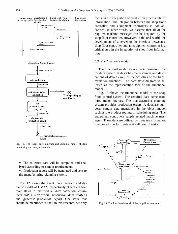
Fig. 12. The event trace diagram and dynamic model of datamonitoring and analysis module.
v. The collected data will be computed and ana-lyzed according to certain requirements.vi. Production report will be generated and sent tothe manufacturing planning system.
Fig. 12 shows the event trace diagram and dy-namic model of DMAM respectively. There are fourmain states in this module: data collection, equip-ment status Õerification, production data analysisand generate production report. One issue thatshould be mentioned is that, in this research, we only
focus on the integration of production process relatedinformation. The integration between the shop floorcontroller and equipment controllers is not ad-dressed. In other words, we assume that all of therequired machine messages can be acquired by theshop floor controller. However, in the real world, thedevelopment of a server or the interface between ashop floor controller and an equipment controller is acritical step in the integration of shop floor informa-tion.
5.3. The functional model
The functional model shows the information flowinside a system. It describes the resources and desti-nations of data as well as the activities of the trans-formation functions. The data flow diagram is se-lected as the representation tool of the functionalmodel.
Fig. 13 shows the functional model of the shopfloor control system. The required data come fromthree major sources. The manufacturing planningsystem provides production orders. A database sup-ports certain data mentioned in the object modelsuch as the product routing or scheduling rules. Theequipment controllers supply related machine mes-sages. These data are utilized by three transformationfunctions to perform relevant cell control tasks.
Fig. 13. The functional model of the shop floor controller.

( )C. Ou-Yang et al.rComputers in Industry 41 2000 213–238 227
Fig. 14 describes the functional model of PSM.There are six sub functions in this model. The oper-ating sequence of these functions has been describedin the dynamic model. The activities for most ofthese functions are trivial. For example, check_re-sources function can be described as:
Žcheck resources part’s routing list, material– – – –.file, workstation file ´capacity status for each
taskFor each task in the part’s routing
Find the required material from material fileIf material quantity is enough
Then check the machine capacity fromworkstation fileIf machine is available
Then finish task checkingElse send ‘‘machine is not available’’to insufficient capacity process– –Else send ‘‘insufficient material’’ toinsufficient capacity process– –
The functional model of DCM is presented in Fig.15. Two major tasks and their related functions are
Ž .dispatching send production commands and coor-– –Ždination identify_shopfloor problem and find– –
.solution . The pseudo codes about function send–production commands can be described as:–
Žsend production commands task no, machine– – – –no, machine status, tool status, material status,– – –
.CAM file ´machine control codes, NC codes– – –
Fig. 14. The functional model of planning and scheduling module.

( )C. Ou-Yang et al.rComputers in Industry 41 2000 213–238228
Fig. 15. The functional model of dispatching and coordination module.
For each operation no–Acquire NC codes from CAM file based on–assigned machine no–While ‘‘machine ready’’ command does not–receive
Wait for a certain period of timeSend ‘‘machine noX is not ready’’ and–Exit
While ‘‘material ready’’ and ‘‘tool ready’’commands do not receive
Wait for a certain period of timeSend ‘‘materials and tools are not ready’’and Exit
Send NC codes and machine control codes toproper machine controllers
As for the function identify shopfloor problem,– –its major role is to translate equipment abnormalconditions from DMAM to shop floor problems. Atable looking approach can be applied in mappingmachine conditions onto shop floor conditions. Forexample, Table 1 shows a few hypothetical examplesabout the mapping between machine conditions andshop floor conditions.
The main task of find solution is to find proper–ways to fix certain identified shop floor problems. Ingeneral, most of the shop floor problems are causedby a single broken down machine. Therefore, themajor concept is to give DCM certain privileges tohandle this kind of shop floor problem without influ-encing the main production schedule. The basic job
( )C. Ou-Yang et al.rComputers in Industry 41 2000 213–238 229
Table 1Mapping between machine conditions and shop floor conditions
Machine conditions Shop floor conditions
Robot-R001 break down I Part loadingrunloading for lathe-L001 is out of order.I Reassign part loadingrunloading tasks for lathe-L001.
Tool-T012 in lathe-L001 is broken I Lathe-L001 is out of process.I Task-Nxxx might be delayed.
AGV-A001 is out of power I Part transportation is out of order.I Reassign part transportation tasks.
of find solution is, for every abnormal machine, to–find another similar machine that has not beenscheduled during the required time. This newly se-lected machine will replace the original machine toperform the same task. In addition, it will informPSM about the modification. However, if find solu-–tion cannot deal with the shop floor condition suchas no replaced machine can be acquired or more thanone equipment break down at a certain time period,this function will notify the manufacturing planningsystem for regenerating work orders.
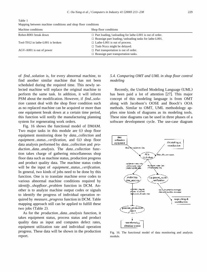
Fig. 16 shows the functional model of DMAM.Ž .Two major tasks in this module are i shop floor
equipment monitoring done by data collection and–Ž .equipment status Õerification, and ii shop floor– –
data analysis performed by data collection and pro-–duction data analysis. The data collection func-– – –tion takes charge of gathering miscellaneous shopfloor data such as machine status, production progressand product quality data. The machine status codeswill be the input of equipment status Õerification.– –In general, two kinds of jobs need to be done by thisfunction. One is to translate machine error codes tovarious abnormal machine conditions required byidentify shopfloor problem function in DCM. An-– –other is to analyze machine output codes or signalsto identify the progress of individual operation re-quired by measure progress function in DCM. Table–mapping approach still can be applied to fulfill these
Ž .two jobs Table 2 .As for the production data analysis function, it– –
takes equipment status, process status and productquality data as input and computes defect rates,equipment utilization rate and individual operationprogress. These data will be shown in the productionreport.
5.4. Comparing OMT and UML in shop floor controlmodeling
Ž .Recently, the Unified Modeling Language UMLw xhas been paid a lot of attention 27 . This major
concept of this modeling language is from OMTalong with Jacobson’s OOSE and Booch’s OOAmethods. Similar to OMT, UML methodology ap-plies nine kinds of diagrams as its modeling tools.These nine diagrams can be used in three phases of asoftware development cycle. The use-case diagram
Fig. 16. The functional model of data monitoring and analysismodule.
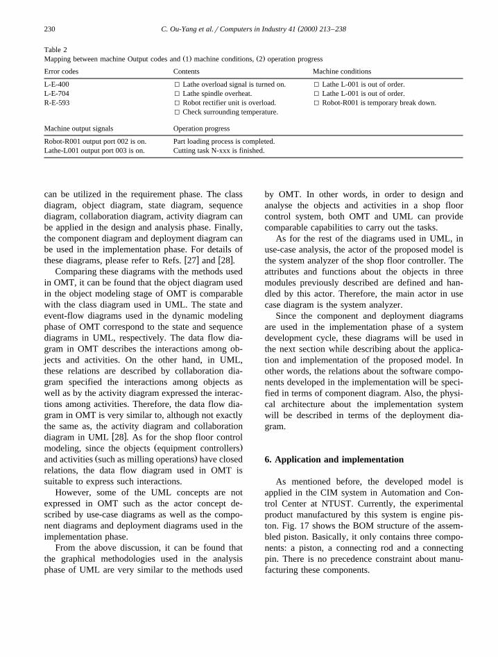
( )C. Ou-Yang et al.rComputers in Industry 41 2000 213–238230
Table 2Ž . Ž .Mapping between machine Output codes and 1 machine conditions, 2 operation progress
Error codes Contents Machine conditions
L-E-400 I Lathe overload signal is turned on. I Lathe L-001 is out of order.L-E-704 I Lathe spindle overheat. I Lathe L-001 is out of order.R-E-593 I Robot rectifier unit is overload. I Robot-R001 is temporary break down.
I Check surrounding temperature.
Machine output signals Operation progress
Robot-R001 output port 002 is on. Part loading process is completed.Lathe-L001 output port 003 is on. Cutting task N-xxx is finished.
can be utilized in the requirement phase. The classdiagram, object diagram, state diagram, sequencediagram, collaboration diagram, activity diagram canbe applied in the design and analysis phase. Finally,the component diagram and deployment diagram canbe used in the implementation phase. For details of
w x w xthese diagrams, please refer to Refs. 27 and 28 .Comparing these diagrams with the methods used
in OMT, it can be found that the object diagram usedin the object modeling stage of OMT is comparablewith the class diagram used in UML. The state andevent-flow diagrams used in the dynamic modelingphase of OMT correspond to the state and sequencediagrams in UML, respectively. The data flow dia-gram in OMT describes the interactions among ob-jects and activities. On the other hand, in UML,these relations are described by collaboration dia-gram specified the interactions among objects aswell as by the activity diagram expressed the interac-tions among activities. Therefore, the data flow dia-gram in OMT is very similar to, although not exactlythe same as, the activity diagram and collaboration
w xdiagram in UML 28 . As for the shop floor controlŽ .modeling, since the objects equipment controllers
Ž .and activities such as milling operations have closedrelations, the data flow diagram used in OMT issuitable to express such interactions.
However, some of the UML concepts are notexpressed in OMT such as the actor concept de-scribed by use-case diagrams as well as the compo-nent diagrams and deployment diagrams used in theimplementation phase.
From the above discussion, it can be found thatthe graphical methodologies used in the analysisphase of UML are very similar to the methods used
by OMT. In other words, in order to design andanalyse the objects and activities in a shop floorcontrol system, both OMT and UML can providecomparable capabilities to carry out the tasks.
As for the rest of the diagrams used in UML, inuse-case analysis, the actor of the proposed model isthe system analyzer of the shop floor controller. Theattributes and functions about the objects in threemodules previously described are defined and han-dled by this actor. Therefore, the main actor in usecase diagram is the system analyzer.
Since the component and deployment diagramsare used in the implementation phase of a systemdevelopment cycle, these diagrams will be used inthe next section while describing about the applica-tion and implementation of the proposed model. Inother words, the relations about the software compo-nents developed in the implementation will be speci-fied in terms of component diagram. Also, the physi-cal architecture about the implementation systemwill be described in terms of the deployment dia-gram.
6. Application and implementation
As mentioned before, the developed model isapplied in the CIM system in Automation and Con-trol Center at NTUST. Currently, the experimentalproduct manufactured by this system is engine pis-ton. Fig. 17 shows the BOM structure of the assem-bled piston. Basically, it only contains three compo-nents: a piston, a connecting rod and a connectingpin. There is no precedence constraint about manu-facturing these components.

( )C. Ou-Yang et al.rComputers in Industry 41 2000 213–238 231
Fig. 17. The BOM of the experimental product.
Ž .Let’s assume a work order file Table 3-1 isreleased from the manufacturing planning system tothe shop floor controller. PSM will select the produc-tion process of each part from the routing file. Theselected routing data for the piston, connecting rodand connecting pin are shown in Table 3-2. For eachprocess in the routing, PSM will check the status ofthe required resources such as raw materials andequipment. The material and workstation files areshown in Tables 3-3 and 4, respectively. If all of therequired resources are available, PSM will determine
proper equipment and issue production tasks forthose machines. Table 3-5 is a hypothetical produc-
Ž .tion task for part ‘‘piston’’ au001-01 manufacturedby lathe L001.
Once the production tasks are delivered to DCM,the related resources will be acquired and resourcefiles will be updated. Then DCM will send a seriesof commands to related equipment in a proper se-
Žquence. For the case of operation L1003-01 in Table.3-5 . The following processes will be carried out by
DCM:
i. Send material retrieval commands to ASrRScontroller to retrieve raw material.ii. Order AGV to move to ASrRS unloadingstation.iii. Output part unloading commands to ASrRScontroller to place raw material on AGV.
Table 3Ž . Ž . Ž . Ž . Ž .Application tables: 1 work Orders, 2 routing list, 3 material list, 4 workstation list, 5 production tasks
Order no. Part name Part no. Quantity Due date
Ž .1A001 Piston au001-01 4 10r5A001 Connecting Rod au001-02 4 10r5
Ž .2Lathe L-001 Milling M-001 CMM C-001
au001-01 1 2au001-02 1 2
Ž .3Item no. Quantitypr001-01 20pr001-02 30
Ž .4Machine no. Machine capacity
Ž .Time mrdrh Status
L-001 10r03r08 usedL-001 10r03r09 availableL-001 10r03r10 availableM-001 10r03r08 availableM-001 10r03r09 available
Ž .5Ž . Ž .Operation no. Part no. Order no. Starting time mrdrh Finishing time mrdrh Machine no. Material no. Quantity
L1003-01 au001-01 A001 10r03r0900 10r03r1100 L-001 pr001-01 4

( )C. Ou-Yang et al.rComputers in Industry 41 2000 213–238232
Ž . Ž .Fig. 18. 1 The deployment diagram about the implementation architecture and, 2 the implementation environment of the shop floorcontroller.

( )C. Ou-Yang et al.rComputers in Industry 41 2000 213–238 233
iv. Order AGV to move to the loading station oflathe L-001.v. Order robot R-001 to pick up the raw materialand to put into L-001.
Ž .vi. Retrieve NC codes for making part au001-01from CAM file and transmits to L-001 controller.vii. Send operation starting command to L-001controller.viii. Once the operation finished signal is received,order robot R-001 to pick up the finished part andplace in the unloading station of L-001.ix. Send AGV to the unloading station and to pickup the finished part.x. Order AGV to move to the loading station ofASrRS and to transfer the finished part to thatstation.xi. Order ASrRS to pick up the finished part andto store in a proper location.
For each step of the processes, DCM will askDMAM to collect machine status data from individ-ual controller in order to monitor process progress.
Currently, a shop floor controller is implementedbased on the proposed model. Fig. 18-1 shows thedeployment diagram about the control structure ofthis system. A Windows NT PC has been used as thehost of this controller. A shop floor communicationsystem Q-Way developed by ATOP Technologies isutilized in the shop floor data collection and trans-mission. There are two major components in the
ŽQ-Way system. A DCA Data Concentration.Adapter is added to the host computer to coordinate
the data communication between the host and ma-chine controllers. For each machine controller, a
Ž .DTA Data Transparency Adapter is linked to itsŽ .communication port RS-232 or RS-485 to translate
the data between the controller and Q-Way. In addi-tion, the communication activities in Q-Way are
Žcarried out by calling various routines in API Appli-.cation Program Interface .
Fig. 18-2 shows the implementation environment.The implementation codes are written by VisualBasic. The data files required by the system such aswork orders, routing files, workstation files, material
Fig. 19. A control window in DCM.

( )C. Ou-Yang et al.rComputers in Industry 41 2000 213–238234
files are stored in the Access database. The DBqueries issued by the controller can be carried out bycalling Code Basic library. In addition, the commu-nication activities between the shop floor controllerand equipment controllers also can be activated bycalling API routines through Code Basic.
Fig. 19 shows one of the control windows inDCM. It includes four sub-windows. The Dispatch-ing-Coordination window can be used in selecting amanufacturing order such as order A001 in Table 3-5from database. Once an order is selected, it will besent to the proper equipment at the predeterminedtime. The equipment status will be shown in theEquipment-Controller window. During the process-ing period, the data about the finished parts will beindicated in the Data-Collection-Equipment win-dow. Finally, most of the data in the above windowsare stored in Data-Monitoring-Analysis window. Inaddition, certain data such as equipment utilization
Ž .rate Equip U R and material utilization rate– –Ž .Material U R will be computed and displayed in– –this window.
Each class diagram shown in three main modulesof the proposed modelis transferred to related com-puter codes during the coding stage. For instance,Fig. 20 describes the transformation of the DataMonitoring and Analysis class shown in Fig. 8 intorelated codes. Each attribute in this class is declaredas a property in the coding including its name anddata type. Also, each operation in the class is writtenas a method which, in turn, is coded as a subroutinethat carries out the related task.
Fig. 21 shows the component diagram specifiedthe relations about the major software components ofthe implementation program. There are two types ofcomponents in this diagram. One is coding compo-nent or class written by Visual Basic and another isAccess database component.
Initially, the Planning and Scheduling class readsrelated data from four databases: Workstation File,Material File, Tool File and Work Order. Based onthe input data, this program will query the informa-tion about part routine from the Routine File databaseand call dispatching rules from Dispatching Rule
Fig. 20. The transformation of object-oriented class into computer codes.

( )C. Ou-Yang et al.rComputers in Industry 41 2000 213–238 235
Fig. 21. The component diagram of the implementation system.
class. Then the data about production tasks will begenerated and stored in Task List database.
Then, the Dispatching and Coordination classreads the data from Task List database and callResource Coordination and Problem Identification
classes to carry out the dispatching function. Thedispatching data will be sent to Workstation Con-troller and Data Monitoring and Analysis classes.Based on the input data, Data Monitoring and Anal-ysis class will connect with Equipment Controller

( )C. Ou-Yang et al.rComputers in Industry 41 2000 213–238236
and Data Collection classes for the analysis of shopfloor data.
7. Discussion and conclusion
In this paper, a shop floor controller model isdeveloped by using Object Modeling Technique. Itsmajor objective is to bridge the gaps between theproduction planning level and manufacturing level ina CIM environment such that production orders canbe properly carried out by the shop floor equipmentand shop floor dynamic conditions also can be fedback to the planning level.
Although OMT can properly model identities,attributes and operations of individual objects as wellas the sequence of operations and data flow in a shopfloor control system, certain criteria which mightaffect the performance of the controller still cannotbe modeled. One is the time critical status about datatransferred within distinct functions. For example, inDMAM, since the malfunction of an equipment needsto be taken cared of as soon as possible in order notto influence the ongoing production process, themessages about abnormal equipment conditionstransferred from equipment status Õerification to– –
Ž .DCM see Fig. 16 are very time critical. On theother hand, the product data transferred from pro-duction data analysis to generate production re-– – – –
Ž .port in Fig. 16 is less time critical compared withthe former case.
Another criterion that has not been considered byOMT is the traffic pattern of data traveling insideand outside of the controller. For instance, in Fig. 16,the equipment data transferred from data collectionequipment might be very short in length but veryhigh in frequency. On the contrary, each productdata transferred from production data analysis– –might be very long in length but very low in fre-quency. This criterion might become an importantfactor during the implementation of the shop floorcontroller in a CIM system such as selecting datacollection equipment or designing shop floor datanetwork.
In addition, this paper also discussed the corre-sponding relations among the OMT and UML mod-eling methodologies. The results show that theyprovide comparative modeling methods during the
design and analysis phase of a modeling cycle. How-ever, UML also includes certain modeling tools usedin the implementation phase. Therefore, these toolshave been added in the application section of thispaper to enhance the proposed shop floor controlmodel.
In conclusion, this paper describes the process ofdeveloping a shop floor controller from modelingstage until implementation. Although the proposedmodel is focused on a CIM system in the educationalenvironment. Several concepts developed from thismodel still can be applied in the shop floor controllerutilized in other environment. For instance, this envi-ronment can be extended to other manufacturingprocesses such as the wafer manufacturing in ICindustries. Since both of the environments have sev-eral similarities. For instance, both environmentsrequire fabrication machines to process parts, robotsto pick and place WIPs, and AGV to transfer parts.Therefore, the modeling methodologies used in modelIC manufacturing process are very similar to themethods used in this paper, except that certain ob-jects, attributes or activities might be considered inthe modeling process. For instance, a tardy task inwafer manufacturing might cause quality problems.Therefore, certain attributes and functions should beincluded to respond to this situation.
The major contributions of this research are:
1. The feasibility of applying OMT in modeling ashop floor control system is proved.
2. An environment for implementing a shop floorcontroller is proposed.
3. An idea of decentralizing the authority of upperplanning level is proposed. That is, in DCM, thesystem can handle certain dynamic shop floorconditions. This can reduce the data flow betweenthe shop floor controller and manufacturing plan-ning system.
Some possible future works include:
1. Improving the modeling methodologies to de-scribe the traffic pattern situation and time criticalproblem of the controller.
2. Developing methodology to evaluate the perfor-mance of the proposed model based on certaincriteria.

( )C. Ou-Yang et al.rComputers in Industry 41 2000 213–238 237
References
w x1 M.P. Groover, Automation, Production Systems, and Com-puter Integrated Manufacturing, Prentice-Hall, 1987.
w x2 in: R. Bernhardt, R. Dillman, K. Hormann, K. TierneyŽ .Eds. , Integration of Robotics into CIM, Chapman and Hall,1992.
w x3 I.T. Franfs, M. Loftus, N.T.A. Wood, Generic manufacturingcell control, International Journal of Operations and Produc-
Ž . Ž .tion Management 11 4 1991 20–32.w x4 T.C. Chang, Expert Process Planning for Manufacturing,
Addison-Wesley, 1990.w x5 G. Harhalakis, L. Mark, A. Johri, B. Cochrane, in: Approach
to Integrating Manufacturing Systems,ASME Proceeding ofManufacturing International 88, Vol. III, p. 255–262, At-lanta, GA, USA, 1988.
w x6 T.D. Poyser, CIM-Computer Integrated Manufacturing, AStrategic Model and Application of Current Technologies,IEEE Proceeding of the 42th Annual Conference of Electri-cal Engineering Problems in Rubber and Plastics Industries,pp. 4–8.
w x7 A.T. Jones, C.R. McLean, A proposed hierarchical controlmodel for automated manufacturing systems, Journal of
Ž . Ž .Manufacturing Systems 5 1 1986 15–25.w x8 B. Boulet, B. Chhabra, G. Harhalakis, I. Minis, J.M. Proth,
Cell controllers: analysis and comparison of three majorŽ .projects, Computers in Industry 16 1991 239–254.
w x9 J. Rumbaugh, M. Blaha, W. Premerlani, F. Eddy, W.Lorensen, Object-Oriented Modeling and Design, Prentice-Hall, 1991.
w x10 K.H. Lee, S. Sen, ICOSS: a two-layer object-based intelli-gent cell control architecture, Computer Integrated Manufac-
Ž . Ž .turing Systems 7 2 1994 100–112.w x11 D.J. Larin, Cell control: what we have, what we’ll need,
Ž .Manufacturing Engineering 1989 41–49, Jan.w x12 B.A. Catron, B.H. Tomas, Generic manufacturing con-
trollers, Proceeding of IEEE International Symposium onŽ .Intelligent Control 1 1988 742–744.
w x13 T. Odajima, T. Torii, in: Functional modeling of the cellcontroller in computer integrated manufacturing systems,Pro-ceeding of the 11th IEEErCHMT International ElectronicsManufacturing Technology Symposium, 1991, pp. 105–109.
w x14 A. Bauer, R. Bowden, J. Browne, J. Duggan, G. Lyons, ShopFloor Control Systems — from Design to Implementation,Chapman and Hall, 1991.
w x15 U. Rembold, B.O. Nuaji, A. Storr, Computer IntegratedManufacturing and Engineering, Addison-Wesley, 1993.
w x16 P. O’Grady, K.H. Lee, An intelligence cell control systemfor automated manufacturing, International Journal of Pro-
Ž . Ž .duction Research 26 5 1988 854–861.w x17 D.M. Dilts, N.P. Boyd, H.H. Whorms, The evolution of
control architecture for automated manufacturing systems,Ž . Ž .Journal of Manufacturing Systems 10 1 1991 79–93.
w x18 K.V. Pandya, in: Development of rules for production plan-ning and control at the cell level,Proceeding of the 3rdInternational Conference on Factory 2000, 1992, pp. 228–233.
w x19 B. Vernadat, Enterprise Modeling and Integration: Principlesand Applications, Chapman and Hall, 1996.
w x20 G.J. Colquhoun, R.W. Baines, R. Crossley, A state of thearts review of IDEF0, International Journal of Computer
Ž . Ž .Integrated Manufacturing 6 4 1993 252–264.w x21 K.Y. Chen, S.S. Lu, A petri-net and entity relationshop
diagram based objected oriented design method for manufac-turing systems control, International Journal of Computer
Ž . Ž .Integrated Manufacturing 10 1–4 1997 17–28.w x22 L.C. Wang, An integrated objected oriented petri-net
paradigm for manufacturing control systems, InternationalŽ . Ž .Journal of Computer Integrated Manufacturing 9 1 1996
73–87.w x23 J.H. Mize, H.C. Bhuskute, D.B. Pratt, M. Kamath, Modeling
of integrated manufacturing systems using an object-orientedŽ . Ž .approach, IIE Transactions 24 3 1992 14–26.
w x24 S.C. Karacal, J.H. Mize, A formal structure for discrete eventsimulation. Part I: modeling multiple level systems, IIE
Ž .Transactions 28 1996 753–760.w x25 S.C. Karacal, J.H. Mize, A formal structure for discrete event
simulation. Part II: object-oriented software implementationŽ . Ž .for manufacturing systems, IIE Transactions 30 1998
217–226.w x26 K.H. Kim, J.W. Bae, J.Y. Song, H.Y. Lee, A distributed
scheduling and shop floor control method, Computer inŽ . Ž .Industrial Engineering 31 3r4 1996 583–586.
w x27 G. Booch, J. Rumbaugh, I. Jacobson, The Unified ModelingLanguage for Object-Oriented Development DocumentationSet Version 0.9. Rational Software, 1996.
w x28 H.E. Eriksson, M. Penker, UML Toolkit, Wiley, 1998.
C. Ou-Yang is a professor of IndustrialManagement Department at NationalTaiwan University of Science and Tech-nology, where he teaches computer inte-grated manufacturing and CAD. Dr.Ou-Yang earned his M.S. and Ph.D.degrees in Industrial and Systems Engi-neering from The Ohio State University.His current research interests includeproduction system integration, enterprisemodeling, shop floor control and con-current engineering.
T.Y. Guan is a quality engineer at Tai-wan Semiconductor ManufacturingŽ .tsmc . Mr. Guan earned his M.S. de-gree in Industrial Management from Na-tional Taiwan University of Science andTechnology. His area of expertise in-cludes shop floor integration and con-trol, semiconductor quality assurance.

( )C. Ou-Yang et al.rComputers in Industry 41 2000 213–238238
J.S. Lin is currently working towards aPh.D. degree in Industrial Managementat National Taiwan University of Sci-ence and Technology. He is a lecturer inthe Industrial Engineering and Manage-ment Dept. at Ming Chi Institute ofTechnology, where he teaches manufac-turing automation, production manage-ment and control. Mr. Lin earned hisB.S. and M.S. degree in Industrial Man-agement from National Taiwan Univer-sity of Science and Technology. His
research interest includes shop floor integration and control, enter-prise modeling and integration.