Embed Size (px)
Citation preview

Head Office: UK Power Solutions Ltd, River View House,
Bonds Mill Estate, Stonehouse, Gloucestershire, GL10 3RF
Company Reg No. 06256696 VAT Reg No. 910 4276 54
CONFIDENTIAL - Revision 1.0
When printed this document becomes uncontrolled. Please ensure you refer to the latest version.
All content and graphics are Copyright © 2016 UK Power Solutions Ltd. All rights reserved.
Reproduction in whole or in part in any form or medium without express permission from UKPS is prohibited
DEVELOPERS GUIDE (GAS)

Introduction & Process
Responsibilities
Excavation for mains pipes
Minimum excavation requirements
Utility pipe and cable positions
Service positions and routes
Service pipe trenches
Meter box installation
General Advice
Plot Connection Request
Contacts
3
4-5
6
7
8
9
10
11
12-13
14
15
Contents

CONFIDENTIAL Revision 1.0 3
Introduction & Process
We will be installing the gas distribution infrastructure to ensure the new supplies you have requested are installed/commissioned to the required metering points. Once this infrastructure has been commissioned it will then become fully owned and maintained by the adopting Network Operator.
An approved design will be provided for you which will have been validated by the adopting Network Operator. It is essential that the elements of the installation that you are responsible for are
installed to the exact specification required on the design, failure to adhere to this could result in the commissioning of the new infrastructure being delayed and/or incurring additional costs, something we are very keen to avoid.
Finally, if there is any part of this project that you are unsure, unhappy or really pleased about, please don’t hesitate to contact us. In addition, we will also provide you with details of our Area Construction Manager should you wish to escalate any queries.
UK Power Solutions aim to provide the highest standard of customer service throughout the entire connection process providing the customer with a single point of contact at every stage of the project.
Smell Gas? To report a gas or carbon monoxide emergency, or if a pipeline is struck (even if no gas leak has occurred) call the National Gas Emergency Service 24 hours a day on 0800 111 999.

Tasks Customer UKPS
Request call off of service connections from UKPS
Provision of Meter Point Reference Numbers (MPRN’s)
Excavation and reinstatement of onsite pipe trenches
Supply and installation of onsite ducting and draw cord
Supply of meterboxes, preformed bends & gas warning marker tape
Installation of meterboxes, preformed bends & gas warning marker tape
Excavation of onsite joint bays
Supply and installation of gas pipe
The below table clearly defines who is responsible for the various tasks required for the installation of the gas services on your site, these may vary slightly if specifically requested at quotation stage. Please check your proposal to confirm or call your Project Manager to discuss.
MaterialsMains Pipe - We will arrange for the mains pipe tobe delivered ready for our teams to install. Pleasetake care of delivered pipe as if any pipes have cuts or scratches to a depth greater than 10% of their wall thickness then they must be discarded.
Requesting WorksOnce the main supply has been installed onto your site you will be able to call off any remaining mains pipe installation and service connections in line with your requirements.
Lead times for calling off work are:• Mains pipe installation – 20 working days• Service connections – 15 working days• Work in public highway – 40 working days
Gas mains pipe installation should be requested through your Dedicated Project Manager.
Responsibilities
4Revision 1.0CONFIDENTIAL

CONFIDENTIAL Revision 1.0 5
Responsibilities (cont.)
Gas Service connections should be requested via the UKPS plot Call Off team by simply filling out the Service “Connection Request Form” (Page 14) and either faxing it to 0845 2577 106 or emailing the form to [email protected].
Please be aware that the below requirements need to have been met prior to our site attendance to ensure the works can be completed without aborted visits.
• Premises are watertight and lockable
• Meter boxes/positions are installed and complete
• Final Ground Lines and Levels are determinable
• Excavations are suitable and safe
• Scaffolding has been removed from our work area
• Ducting has been installed to the correct specification and position
CONFIDENTIAL Revision 1.0

CONFIDENTIAL Revision 1.0 6
UK Power Solutions is responsible for laying all mains in trenches (unless otherwise stated) to the following minimum depths, using the diagram opposite as a guide:
Minimum depth of cover for mains pipes
Road and vehicular/ pedestrian access
750mm
Footpath 600mm
Verges 750mm
Open fields and agricultural land
1100mm
Excavation for mains pipes
75m
m -
100m
m fi
ne fi
ll su
rrou
nd
Gas warning marker tape to belaid at least 150mm above main
Ground Level
300mm approx. trench width
Ground Level
The pipe should be installedwith a sand/finefill surround to a
minimum cover of 75mm toprevent damage during final
reinstatement
For trench with multiple utilities gas pipe must beminimum 250mm from all other pipes and cables
Bottom of trench must be leveland free from sharp stones.
Recommended Depth of Cover for Mains Pipes
Road & vehicular/pedestrian areas 750mm
Footpath 600mm
Verges 750mm
Open fields andagricultural land 1100mm
xxx is responsible for laying all mains 63mm in diameter and above intrenches pre-excavated by the client (unless otherwise stated) to thefollowing minimum depths, using the diagram opposite as a guide.
300mm plus external pipe diameter trench width
250mm

CONFIDENTIAL Revision 1.0 7
Minimum excavation requirements
Minimum excavation requirements to support connections. Excavation base to be 150mm below pipe
Connection typeApplicable mains diameters
Excavation sizeAdditional bell hole in middle in direction of offtake
Excavation shape
End on connection(Note: the excavation dimension is for the live main to be exposed)
≤180mm mains diameter
2.1m x 0.7m n/a
250/315mm diameter
3.3m x 0.9m n/a
Insert Tee
≤180mm mains diameter
7.3m x 0.7m 1m x 0.7m
250/315mm diameter
10.6m x 0.9m 1m x 0.9m
Branched offtake
≤180mm mains diameter
1.5m x 0.7m 1m x 0.7m
250/315mm diameter
1.5m x 0.9m 1m x 0.9m

CONFIDENTIAL Revision 1.0 8
Utility pipe and cable positions
The diagram opposite illustrates the recommended positioning for new utility apparatus in a 2m footway.
Depth of cover required in a Carriageway or Verge is 750mm with proximities to other utilities remaining as per the diagram.
The gas network design will be discussed at the pre-start meeting. If you have any subsequent problems or queries, please contact your Project Manager who will be happy to advise and help resolve any issues.
Please also note that a minimum 250mm clearance must be achieved from the gas main to all other utilities.
TelecommunicationsDepth 350mm
Water Depth 750mm
Gas Depth 600mm
Cable TV/Communications Depth 250mm - 350mm
430260270295295450
Electricity Depth HV450mm - 1200mm, LV 450mmBoundary
Surface
Box
Boundary
430260270295295450
2000
Carriageway
Utility Pipe and Cable Positions
Note: This drawing is NOT to scale
The diagram opposite illustrates the recommended positioningfor new utility apparatus in a 2m footway.
Depth of cover required in a carriageway or verge is 750mm withproximities to other utilities reaming as per the diagram.
The gas network design will be discussed at the pre-startmeeting, if you have any subsequent problems or queries thenplease contact your Project Manger who will be happy to adviseand help resolve any issues.
Smell Gas? To report a gas or carbon monoxide emergency, or if a pipeline is struck (even if no gas leak has occurred) call the National Gas Emergency Service 24 hours a day on 0800 111 999.

CONFIDENTIAL Revision 1.0 9
Service positions and routes
PositionsThe position of the meter must be on the wall of the property facing the parent main, or, where it is required, on the side of the property no more than 2m down the gable. Meters cannot be installed to the rear of the property.
If you feel you cannot achieve the requirements, please contact your Project Manager.
RoutesThe service pipe must not be installed in any land other than that of the property it is supplying or public/shared driveway. Where a service is required to cross the road to a main on the opposite footpath, it must be laid in an individual road crossing (it is acceptable to install ducts for these road crossings as required). We will try to minimise this as much as possible during the design stage.
Examples of serviceroutes where roadcrossings required.
Note: Drawings are NOTto Scale
Service Positions
All services must be laid individually and perpendicular to the building takingthe shortest route practicable to the main unless otherwise indicated on theapproved construction drawing.
The position of the meter must be on the front of the property or where it isrequired on the side of the property must be no more than 2m from the frontgable end.
Where a service is required to cross the road to a main on the oppositefootpath it must be laid an individual road crossing. We will try and minimisethis as much as possible during the design stage. If you feel you cannotachieve the requirements, please contact your Project Manager.
Min 250
2m M
ax
All services must be laid individually and perpendicular to the building taking the shortest route practicable to the main, unless otherwise indicated.

Service pipe trenchesYour Responsibilities:
Lay service pipes as per construction drawing. Ensure 75mm cover of finefill material round whole of pipe. Place marker tape above finefill. Provide and install yellow perforated ducts for road crossings. Excavate at meter positions and to soft fill over gas main. Install meter boxes and doors/lids.
Minimum Depth of Cover for Service Pipes:
Private Ground - 375mm Footpath/Highways - 450mm
75m
m -
100m
m fi
nefil
l sur
roun
d
Gas warning marker tape to belaid at least 150mm above main
Ground Level
300mm approx.trench width Ground Level
The pipe should be installedwith a sand/finefill surround to a
minimum cover of 75mm toprevent damage during final
reinstatement
For trench with multiple utilities gas pipe must beminimum 250mm from all other pipes and cables
Bottom of trench must be leveland free from sharp stones.
450m
m d
epth
960mm
600m
m M
in C
over
500m
m
450m
m M
in C
over
Main End Termination
Plastic seal inpipe end
Gas Main
Road
PE GasService
Gas warning marker tape to be laid at least 150mm above service
For trench with multiple utilities gas pipe must be minimum 250mm from all other pipes and cables
CONFIDENTIAL Revision 1.0 10
Your responsibilities:Ensure a minimum of 75mm of fine fill material around the service pipe.
Place marker tape above fine fill
Provide and install yellow perforated ducts (to BS4962) for road crossings
Excavate at meter positions and to soft fill over gas main
Install meter boxes and doors/lids
Minimum depth of cover for service pipes:Private Ground = 375mmFootpath/Highways = 450mm

CONFIDENTIAL Revision 1.0 11
Meter box installation
Unibox
Fitted at ground level submerged into the ground by 75mm or fixed onto the wall ensuring the ground level is as per indicator on the box.
Must be a minimum 150mm away from any air bricks.
Ensure box is supported following installation.
Fit meter box lid.
Route outlet pipe through right hand side of box.
Make continuity bond to outlet.
Provide 2m of excavation from the front of the box, 500mm wide,
Flush Fit or Bolt On
Fix meter box to wall
Fit meter box door
Securely fit spigot outlet to prevent passage of gas into property
The meter installer will seal the route of the outlet pipework and label the meter accordingly
Flush fit or Bolt On
Fix meter box to wall Fit meter box door Securely fit spigot outlet to
prevent passage of gas intoproperty.
The meter installer will seal theroute of the outlet pipework andlabel the meter accordingly.
Unibox
Fitted at ground level submerged intogroud by 75mm of fixed onto the wall.
Must be minimum 150mm away fromany air brick where no risk of waterentering.
Ensure box supported followinginstallation.
Fit meter box lid. Route outlet pipe through right hand
side of box. Make continuity bond to outlet pipe.
Provide 2m of excavation fromthe front of the box - 500mm wide
. Developer toexcavate toexposeservice pipe
Ground levelindicator on box
DPC
Emergency ControlValve (ECV)
GRP sleeve fittedby our team DPC
FinishedLevel
Developer toexcavate 2m backdown service routefrom box position
PVC black bendfitted by our team
Developer to excavateto expose service pipe
Gas Pipe ExternalDiameter
Duct internalDiameter
20/25/32mm 50mm63mm 100mm90mm 150mm
125/180mm 225mm250mm 350mm
Meter Box Installation Details(NTS)
Gas Meter Box
ElectricalMeter Box
75
480mm
500m
m
390mm 205mm
290mm
Gas Meter Box Detail(Scale 1:10)
Developer toexcavate to expose service duct
Gas Meter Box
duct

12Revision 1.0CONFIDENTIAL
General Advice
Sealing of outlets
The meter installer will fit the meter and label accordingly. It is your responsibility to ensure that the meter box outlet spigot or any through-wall sleeve carrying the meter outlet pipework is correctly sealed to prevent the passage of gas into the property.
Failure to do this is a breach of the Gas Safety (Installation and Use) Regulations.
Handling of Pipe
Mains pipe may be delivered to site in coils or straight lengths. Individual smaller coils are generally capable of being handled manually. However, larger coils will require mechanical lifting using soft straps.
The handling of straight pipe lengths requires some expertise, especially once any pipe packs have been unbound.
UK Power Solutions will move individual mains pipe lengths from the storage point to the construction location.
Electrical Cross Bonding
An electrical cross bonding wire (where required) should be connected to the gas meter outlet in accordance with IEE Regulations. When the bonding wire enters a built-in box from the rear it must pass through the outlet installation pipe spigot and be contained within the seal.
The box must not be broken to accommodate the bonding wire.
Please remember that you are not permitted to lay any gas pipe. This must be done by one of our qualified installers.
CONFIDENTIAL Revision 1.0 1313 Revision 1.0CONFIDENTIAL
General Advice (cont.)
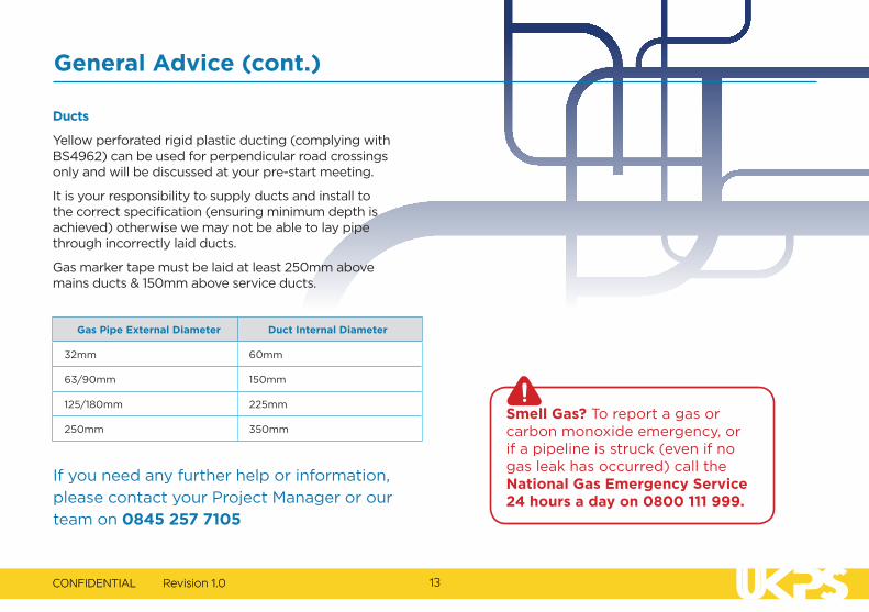
Ducts
Yellow perforated rigid plastic ducting (complying with BS4962) can be used for perpendicular road crossings only and will be discussed at your pre-start meeting.
It is your responsibility to supply ducts and install to the correct specification (ensuring minimum depth is achieved) otherwise we may not be able to lay pipe through incorrectly laid ducts.
Gas marker tape must be laid at least 250mm above mains ducts & 150mm above service ducts.
If you need any further help or information,
please contact your Project Manager or our
team on 0845 257 7105
Gas Pipe External Diameter Duct Internal Diameter
32mm 60mm
63/90mm 150mm
125/180mm 225mm
250mm 350mm
Smell Gas? To report a gas or carbon monoxide emergency, or if a pipeline is struck (even if no gas leak has occurred) call the National Gas Emergency Service 24 hours a day on 0800 111 999.

14Revision 1.0CONFIDENTIAL
Se
rvice
Con
nec+
onR
eque
st
FM
186
Plot
Con
nec+
onR
eque
st
E-M
ail:
plot
callo
ff@uk
pow
erso
lu+o
ns.co
.uk
Tel:
084
525
771
05
Fax:
084
525
771
06
PLEA
SEN
OTE:
Am
inim
umo
f15
wor
king
day
sno8
cefo
rser
vice
conn
ec+o
nsis
requ
ired
and
am
inim
umo
f5p
lots
to
beco
nnec
ted
perv
isit.
Inth
eev
ento
faca
ncel
la+o
n/po
stpo
nem
enta
min
imum
of5
day
sno8
ceis
requ
ired.
A
sepa
rate
conn
ec8o
nre
ques
tfor
mis
requ
ired
fore
ach
prop
osed
dat
ean
da
new
conn
ec8o
nre
ques
tfor
mis
re
quire
dfo
rany
am
endm
ents
tob
ooki
ng.S
itew
illb
ere
quire
dto
sign
off
any
abor
ted
wor
ksin
the
boxb
elow
.Th
ere
ques
ted
conn
ec+o
nsw
orks
will
not
take
pla
ceu
n+lt
heb
elow
requ
irem
ents
oft
hea
dop+
ngn
etw
ork
owne
rha
veb
een
met
prio
rto
ours
itea
Send
ance
: •P
rem
isesa
rew
ater
+ght
and
lock
able
•
Expo
sea
min
imum
of1
.2m
ofm
ain
fors
ervi
cejo
in+n
g
•Met
erb
oxes
/hoc
key
s+ck
s/pr
efor
med
ben
dsa
refi
xed
•Fi
nalg
roun
dlin
esa
ndle
vels
are
appr
opria
te
•All
exca
va+o
nsa
resu
itabl
ean
dsa
fe
•D
uc+n
g/co
ntai
nmen
thas
bee
nin
stal
led
toth
eco
rrec
t
sp
ecifi
ca+o
nan
dpo
si+on
Date
ofR
eque
st:
UKPS
Pro
ject
No:
Site
Nam
e:Si
teC
onta
ct:
Site
Add
ress
:
TelN
o:Em
ail:
FaxN
o:
Prop
osed
Dat
e:Fo
rUKP
SUs
eOn
ly
Confi
rmed
Dat
e:
Plot
Nu
mbe
r
Elec
tric
(+ck
)Ga
s(+c
k)
Com
men
ts
Site
Age
nt
toP
rinta
nd
Sign
for
Abor
ted
wor
ks
Outs
ide
Met
er
Box
Inte
rnal
Stre
et
Light
Met
erB
oxIn
tern
alBu
ilt-in
Grou
nd
Co
nfide
n+al
Allc
onte
nta
ndg
raph
icsa
reC
opyr
ight
©2
015
UKP
ower
Sol
u+on
sLtd
.All
right
sres
erve
d.
Revi
sion
1.2
Repr
oduc
+on
inw
hole
ori
npa
rtin
any
form
orm
ediu
mw
ithou
texp
ress
per
miss
ion
from
UKP
Sis
proh
ibite
d.
ForU
KPS
Use
Only
PC
O/__
____
___
EXAMPLE

CONFIDENTIAL Revision 1.0 15
Contacts
Project Manager:
Mobile:
Office:
Email:
Connections Co-ordinator:
Mobile:
Office:
Email:
Regional Construction Manager:
Mobile:
Office:
Email:
Revision 1.0CONFIDENTIAL 15

Tel: 0845 257 7105 | Fax: 0845 257 7106 | Email: [email protected]
www.ukpowersolutions.co.ukRegistered in England & Wales. Registered Address: UK Power Solutions Ltd Head Office, River View House, Bonds Mill Estate, Stonehouse, GL10 3RF
UK Power Solutions Ltd London Office, 4th Floor West World, West Gate, Ealing, London, W5 1DT
Company Reg No. 06256696 VAT Reg No. 910 4276 54
All content and graphics are Copyright © 2017 UK Power Solutions Ltd. All rights reserved.
Reproduction in whole or in part in any form or medium without express permission from UKPS is prohibited