Embed Size (px)
Citation preview
Revised January 2011
5.0 PLAN FORMAT AND REQUIREMENTS – WATER, RECYCLED WATER AND SEWER The Developer’s engineer shall prepare system improvement plans that are clear, concise, and meet Western’s standards. A set of plans that meet all the requirements set forth herein, but are difficult to interpret, mislead the Contractor, confuse the reader, or do not address previous plan check comments, are unacceptable and will be subject to rejection without review. 5.01 SHEET FORMAT – GENERAL Drawings shall be imprinted on ANSI D size 24" x 36" mylar (4 mil double matted) sheets with Western’s standard title blocks as shown in (Section 5.05). Please contact Western’s engineering department for a copy of the cover sheet format in AutoCAD. The improvement plans shall be professional quality especially prepared as WATER DRAWINGS, RECYCLED WATER DRAWINGS, or SEWER DRAWINGS. Work shall be of standard engineering practice and shall be well arranged, neat, legible and present the proposed construction without confusion. Applicable blue prints submitted for checking shall also be clear, bright duplications. Water and sewer design shall be shown on separate drawings. Drawings shall show both plan and profile of the facilities. The profile shall be shown on gridline background and shown vertically above the plan. All drawings shall be drawn to scale using 1”=40’ on the horizontal scale, and 1”=4’ (preferred) or 1”=8’ on the vertical scale. Scale bars shall be provided. Match lines and continuations from sheet to sheet shall be used and identified with applicable station points and cross-reference. Always indicate true north with a suitable north arrow. Indicate tract number and sheet number on all drawings. Each sheet shall have a title block with tract number, street name and stations appearing on that sheet. For special assemblies, unusual and/or complex connections provide a detail schematic (preferably on the same sheet). The detail schematic shall be drawn to scale, show pipe size, and shall fully identify all the parts in the detail. Show and call out all special features and indicate scale. The Engineer shall note on the plans, all connections to existing water, recycled water, and sewer facilities and note who is to construct them. Contractors are not authorized to make connections to existing facilities, unless approved by Western’s staff and under continuous inspection by Western. Contractors shall not operate any valve or appurtenance on any portion of Western’s system that is under pressure. Any facilities to be abandoned shall be clearly identified. 5.02 COVER SHEET As a minimum, the Cover Sheet shall show the following:
1. General notes (Section 5.06 for Water Drawings and Section 5.07 for Sewer Drawings). Said notes shall include engineered fire flow requirements.
2. Legend with Standard Western Symbols (Section 5.05) 3. Numbered construction notes with Estimate of Quantities (Section 5.05)
Revised January 2011
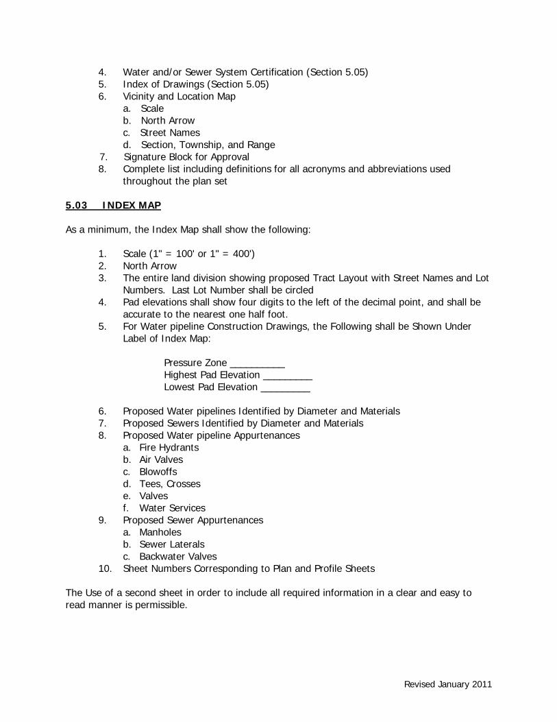
4. Water and/or Sewer System Certification (Section 5.05) 5. Index of Drawings (Section 5.05) 6. Vicinity and Location Map a. Scale b. North Arrow c. Street Names d. Section, Township, and Range
7. Signature Block for Approval 8. Complete list including definitions for all acronyms and abbreviations used
throughout the plan set 5.03 INDEX MAP As a minimum, the Index Map shall show the following:
1. Scale (1" = 100' or 1" = 400') 2. North Arrow 3. The entire land division showing proposed Tract Layout with Street Names and Lot
Numbers. Last Lot Number shall be circled 4. Pad elevations shall show four digits to the left of the decimal point, and shall be
accurate to the nearest one half foot. 5. For Water pipeline Construction Drawings, the Following shall be Shown Under
Label of Index Map: Pressure Zone __________ Highest Pad Elevation _________ Lowest Pad Elevation _________ 6. Proposed Water pipelines Identified by Diameter and Materials 7. Proposed Sewers Identified by Diameter and Materials 8. Proposed Water pipeline Appurtenances a. Fire Hydrants b. Air Valves c. Blowoffs d. Tees, Crosses e. Valves f. Water Services 9. Proposed Sewer Appurtenances a. Manholes
b. Sewer Laterals c. Backwater Valves
10. Sheet Numbers Corresponding to Plan and Profile Sheets The Use of a second sheet in order to include all required information in a clear and easy to read manner is permissible.

Revised January 2011
5.04 PLAN AND PROFILE FORMAT The plan/profile sheets shall be drawn at a horizontal scale of 1"=40' and a vertical scale of 1"=4'. A vertical scale of 1" = 8' is permissible if approved by Western prior to preparation of the construction drawings. As a minimum, the drawings shall show the following: 5.04.01 Plan Format Requirements
a. Title Block - Title block shall include Tract Number, street name, and stations. b. North Arrow - North Arrow shall point up or to the left if possible to conform
with stationing (see item K). c. Street Names - All street names shall be shown. d. Lot Lines - All lot lines and parcel lines shall be shown. All lots shall be
numbered or labeled. All adjacent tracts shall be identified. e. Right-of-Way - Existing and proposed right-of-way shall be identified with
dimensions for same shown. f. Curbs - Existing and/or proposed curbs shall be identified with dimensions
from street centerline shown. g. Fee Title Parcels - Existing or proposed fee title parcels shall be identified
with dimensions for same shown. h. Utilities - All existing and proposed utilities shall be shown including, but not
be limited to, water (existing Western water pipelines shall be identified by Western Plan No.), recycled water (existing Western water pipelines shall be identified by Western Plan No.), sewer (existing Western sewer pipelines shall be identified by Western Plan No.), gas, power, telephone, storm drain, irrigation, traffic, and cable television. Each utility shall be identified with a symbol and the size of the utility shall be shown. In addition, any facilities to be identified shall be clearly identified. If there is significant amount of existing facilities a separate sheet may be required to indicate if they’re to be abandoned, salvaged, protected in place or otherwise indicate their disposition.
i. Existing and Proposed Improvements - All existing surface improvements shall be shown including, but not limited to, curb and gutter, edge of pavement, power poles, driveways, sidewalks, and fences. If there is a significant amount of existing facilities a separate sheet may be required to indicate if they are to be abandoned, salvaged, protected in place or to otherwise indicate their disposition.
j. Proposed Pipeline - Proposed pipeline shall be indicated with a heavy line. For water pipelines, dimensions from street centerline to centerline of water pipeline and from centerline of water pipeline to existing or proposed curb shall be shown. For sewers, dimensions from street centerline to centerline of sewer shall be shown.
k. Stationing - For water pipelines, stationing along the centerline of the improvement is acceptable. For sewers, stationing shall be along the centerline of the sewers. Unless otherwise specified, stationing shall increase from left to right. Stationing shall be identified with tick marks at 100' intervals.

Revised January 2011
For water pipelines and/or sewers with curves, stations for the beginning and end of each curve shall be shown. In addition, a curve data table shall be included showing the delta, curve radius, curve length, and tangent length for each curve.
l. Match Lines – Match lines for each end of the sheet shall be shown as follows:
Sta 15+00.00 Match Line See Sheet 5
m. Water pipelines - Water pipe lines and appurtenances (valves, fittings, thrust blocks, fire hydrants, air valves, water services, and blowoffs) shall be identified by numerical identification and construction notes with the following sample format:
1 8" C-900 (DR14 _____) PVC water pipeline installed per WMWD Std. Dwg. Nos. W-1540 and W-1550.
2 1" Domestic Water Service per WMWD Std. Dwg. No. W-0070. 3 4" Blowoff Assembly per WMWD Std. Dwg. No. W-0214.
All water pipeline appurtenances including valves, tees, crosses, elbows, plugs, thrust blocks, fire hydrants, air valves, and blowoffs shall be identified by Station and a numerical identification. Water services shall be identified by numerical identification only (Stations not required); however, a table listing all of the water service stations shall be included with the “as-built” drawings and shall be a requirement of final inspection. Only those construction notes that apply to each sheet shall be shown. All connections to existing water system shall be identified by station and size. Details for connections shall be used where required. Each connection shall have the following note, "Connection by Contractor with continuous inspection by Western".
n. Recycled Water pipelines – Recycled water pipe lines and appurtenances (valves, fittings, thrust blocks, air valves, water services, and blowoffs shall be identified by numerical identification and construction notes with the following sample format:
1 8" C-900 (DR14 _____) PVC water pipeline installed per WMWD Std. Dwg. Nos. W-1540 and W-1550.
2 1" Recycled Water Service per WMWD Std. Dwg. No. W-1270 3 6" Blowoff Assembly
All water pipeline appurtenances including valves, tees, crosses, elbows, plugs, thrust blocks, air valves, and blowoffs shall be identified by Station and a

Revised January 2011
numerical identification. Recycled water services shall be identified by numerical identification only (Stations not required); however, a table listing all of the recycled water service stations shall be included with the “as-built” drawings and shall be a requirement of final inspection. Only those construction notes that apply to each sheet shall be shown. All connections to existing recycled water system shall be identified by station and size. Details for connections shall be used where required. Each connection shall have the following note, "Connection by Contractor with continuous inspection by Western".
o. Sewer Pipelines – Sewer pipeline and appurtenances (sewer laterals,
manholes, and backwater valves) should be identified by numerical identification and construction notes with the following sample format:
1 8" SDR-35 PVC sewer per WMWD Std. Dwg. No. W-1010. 2 48" Dia. Sewer Manhole per WMWD Std. Dwg. No. W-1070. 3 4" Sewer Lateral per WMWD Std. Dwg. No. W-1050.
All sewer appurtenances except sewer laterals shall be identified by station and a numerical identification. Sewer laterals shall be identified by numerical identification only (stations not required); however, a table listing all of the sewer lateral stations shall be included with the “as-built” drawings and shall be a requirement of final inspection.
Only those construction notes that apply to each sheet shall be shown. All connections to existing sewer system shall be identified by station and size. Details for connections shall be used where required. Each connection shall have the following note, "Connection by Contractor with continuous inspection by Western".
5.04.02 Profile Format Requirements
Only profiles for water, recycled water, and sewer shall be shown. All other utility profiles shall not be shown unless conflicting, or where crossing over or under (i.e. storm drain).
a. Stationing - Stations shall be shown along bottom of profile at 100 foot
intervals. Profile stationing shall line up with plan stationing.
b. Elevations - Elevations shall be shown at even gridlines on both ends of the profile sheet.

Revised January 2011
c. Existing and Proposed Ground Surface - Existing ground surface or pavement over the proposed pipeline shall be identified as follows:
Existing Top of Pavement (or ground surface) over Centerline of Water pipeline (or sewer). Proposed ground surface or pavement over the proposed pipeline shall be identified as follows: Proposed Top of Pavement (or ground surface) over Centerline of Water pipeline (or sewer).
d. Match Lines - Match lines for each end of sheet shall be shown as follows: Sta 15+00.00 Match Line See Sheet 5 e. Water and Recycled Water pipelines:
Water pipeline Identification - Flow lines of proposed water pipelines shall be identified as follows: FL __" C-900 (DR-___) PVC Water pipeline. Both the flow line and top of water pipelines shall be shown. Water pipeline Length - At top of profile, water pipeline length shall be identified as follows: ____ L.F. of __" C 900 (DR-__) PVC Water pipeline. Restrained Joints - Locations that require restrained joints shall be identified in the profile and indicate the full span and length of where the pipe is restrained as follows: Welded Steel Pipe Full weld double pass all joints PVC Pipe Restrained joints Stationing and Flow Line Elevations - Pipeline stationing and flow line elevations shall be shown for each grade break as follows:
Sta 14+00.00 GB 1192.35 FL

Revised January 2011
Pipeline stationing and flow line elevations shall be shown for each tee, cross, air valve, and blowoff as follows:
Sta 12+25.00 Construction Note (s) Number 1190.00 FL
Pipeline stationing shall be shown for all fire hydrants, elbows, BC's, and EC's as follows:
Sta 12+25.00 Construction Note (s) Number
All pipeline stationing and flow line elevations shall be placed below the water pipeline. Pipeline Slopes - Minimum slopes shall be 0.0050. Pipe slopes shall be shown between all grade breaks to four decimal places (i.e. +0.0075) with + or – for direction of slope. Pipe Cover - For 8" water pipelines, the pipe cover shall be 3.0' and for water pipelines 12" and larger the pipe cover shall be 4.0'. Utility Crossings - Where water pipelines cross over utilities the drawings shall show the elevations for the bottom of the water pipeline and the top of the utility. Where water pipelines cross under utilities the drawings shall show the elevations for the top of the water pipeline and the bottom of the utility.
f. Sewers
Sewer Identification - Flow line of proposed sewers should be identified as follows: FL __" SDR-35 PVC Sewer. Both the flow line and top of sewers shall be shown. Stationing and Flow Line Elevation - Sewer stationing and flow line elevations shall be shown at inlet and outlet of each sewer manhole as follows:
Sta 12+25.00 1192.35 FL
A minimum drop of 0.2' shall be shown across each manhole.
Revised January 2011
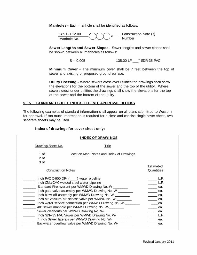
Manholes - Each manhole shall be identified as follows:
Sta 12+12.00 Construction Note (s) Number Manhole No.
Sewer Lengths and Sewer Slopes - Sewer lengths and sewer slopes shall be shown between all manholes as follows: S = 0.005 135.00 LF ___" SDR-35 PVC
Minimum Cover - The minimum cover shall be 7 feet between the top of sewer and existing or proposed ground surface.
Utility Crossing - Where sewers cross over utilities the drawings shall show the elevations for the bottom of the sewer and the top of the utility. Where sewers cross under utilities the drawings shall show the elevations for the top of the sewer and the bottom of the utility.
5.05 STANDARD SHEET INDEX, LEGEND, APPROVAL BLOCKS The following examples of standard information shall appear on all plans submitted to Western for approval. If too much information is required for a clear and concise single cover sheet, two separate sheets may be used. Index of drawings for cover sheet only:
INDEX OF DRAWINGS Drawing/Sheet No. Title 1 of Location Map, Notes and Index of Drawings 2 of 3 of Estimated Construction Notes Quantities _____ _ inch PVC C-900 DR- (____) water pipeline _____ L.F. inch CML/CMC welded steel water pipeline _____ L.F. _______ Standard Fire hydrant per WMWD Drawing No. W-________ _____ ea. inch gate valve assembly per WMWD Drawing No. W-________ _____ ea. inch blow-off assembly per WMWD Drawing No. W-________ _____ ea. inch air-vacuum/air-release valve per WMWD No. W-________ _____ ea. inch water service connection per WMWD Drawing No. W-________ ____ea. _______ 48” sewer manhole per WMWD Drawing No. W-________ _____ ea. _______ Sewer cleanouts per WMWD Drawing No. W-________ _____ ea. inch SDR-35 PVC Sewer per WMWD Drawing No. W-________ _____ L.F. ______ 4 inch Sewer laterals per WMWD Drawing No. W-________ _____ ea. _______ Backwater overflow valve per WMWD Drawing No. W-________ _____ ea.

Revised January 2011
Symbol Legend for cover sheet only:
Certification blocks appear on certain sheets as indicated below: a. Cover Sheet (only) of plans for system improvements proposed to become part of
Western shall have the following: WATER CERTIFICATION BLOCK I certify that the design of the Water System in Tract No. ________ is in accordance
with the Water System master plans of Western Municipal Water District of Riverside County, and that the water service, storage and distribution system will be adequate to provide water service to such tract. This certification does not constitute a guarantee that it will supply water to such tract at any specific quantities, flows or pressures for fire protection or any other purpose.
_________________________________________ _______________ DEREK KAWAII, DIRECTOR OF ENGINEERING C54253 DATE
Revised January 2011
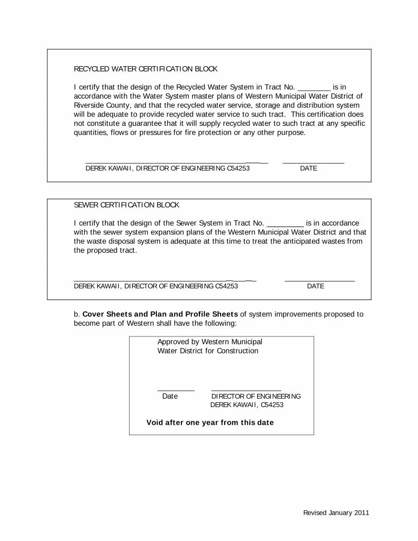
RECYCLED WATER CERTIFICATION BLOCK I certify that the design of the Recycled Water System in Tract No. ________ is in
accordance with the Water System master plans of Western Municipal Water District of Riverside County, and that the recycled water service, storage and distribution system will be adequate to provide recycled water service to such tract. This certification does not constitute a guarantee that it will supply recycled water to such tract at any specific quantities, flows or pressures for fire protection or any other purpose.
_______________________________________ __ _______________ DEREK KAWAII, DIRECTOR OF ENGINEERING C54253 DATE SEWER CERTIFICATION BLOCK I certify that the design of the Sewer System in Tract No. _________ is in accordance
with the sewer system expansion plans of the Western Municipal Water District and that the waste disposal system is adequate at this time to treat the anticipated wastes from the proposed tract.
_____________________________________ ___ _ _________________ DEREK KAWAII, DIRECTOR OF ENGINEERING C54253 DATE
b. Cover Sheets and Plan and Profile Sheets of system improvements proposed to become part of Western shall have the following:
Approved by Western Municipal Water District for Construction
_________ _________________ Date DIRECTOR OF ENGINEERING DEREK KAWAII, C54253 Void after one year from this date

Revised January 2011
c. Cover Sheet of system improvement plans for other agencies that need review by Western for non-interference compliance shall have the following:
REVIEWED BY: WESTERN MUNICIPAL WATER DISTRICT for Non-Interference Compliance SHEET _________ THROUGH _________ __________________________________ Derek Kawaii Director of Engineering Date: _______________
5.06 GENERAL NOTES FOR WATER PIPELINES 1. WATER SYSTEM IMPROVEMENTS SHALL BE CONSTRUCTED BY THE DEVELOPER FOR
DEDICATION TO WESTERN MUNICIPAL WATER DISTRICT (WESTERN). CONSTRUCTION, MATERIALS, TESTING, AND INSPECTION SHALL COMPLY WITH WESTERN’S STANDARDS. THE INSTALLATION SHALL MEET OR EXCEED THE REQUIREMENTS OF ALL PUBLIC AGENCIES HAVING JURISDICTION AND THE AMERICAN WATER WORKS ASSOCIATION (A.W.W.A.) STANDARDS. FAILURE TO MEET THESE REQUIREMENTS WILL BE CAUSE FOR REJECTION.
2. CONSTRUCTION OF THE WATER SYSTEM IMPROVEMENTS SHALL NOT COMMENCE
UNTIL THE DEVELOPER’S ENGINEER HAS CERTIFIED THAT ALL STREETS ARE CONSTRUCTED TO .2’ OF SUB-GRADE. WATER PIPELINES SHALL BE INSTALLED AFTER CONSTRUCTION OF CURB & GUTTER, SEWER, STORM DRAIN, AND PRIOR TO THE PLACEMENT OF CROSS-GUTTERS, SPANDRELS, AND PAVING. CONTACT UNDERGROUND SERVICE ALERT 811 PRIOR TO ANY EXCAVATION.
3. ANY REVISION TO THESE DRAWINGS MUST BE APPROVED IN WRITING BY WESTERN.
CONTACT UNDERGROUND SERVICE ALERT 811 PRIOR TO ANY EXCAVATION.
4. PIPE, FITTINGS, VALVES AND APPURTENANCES SHALL BE OF THE PIPE PRESSURE CLASS (NOT W.W.P. CLASS) SHOWN ON THE PROFILE OF THESE PLANS. (NOTE: CAST IRON FITTINGS ARE NOT ALLOWED.)
5. FINISH GRADE COVER OVER PIPE SHALL BE MINIMUM 36 INCHES FOR PIPELINES LESS
THAN 12 INCHES IN DIAMETER AND MINIMUM 48 INCHES FOR PIPELINES 12” AND GREATER IN DIAMETER. WHEN THE WATER PIPELINE ENCOUNTERS AN OBSTRUCTION AND CROSSING OVER THE OBSTRUCTION WILL RESULT IN LESS THAN MINIMUM COVER, THE WATER PIPELINE SHALL CROSS UNDER THE OBSTRUCTION (MINIMUM 12” CLEARANCE). ADD COVER OVER PIPE AT INTERIM GRADE PRIOR TO FINAL GRADING
Revised January 2011
AND ASPHALT PLACEMENT. MINIMUM 30” OF COVER SHALL BE MAINTAINED AT ALL TIMES DURING CONSTRUCTION OF SITE IMPROVEMENTS. DEPTH GREAT THAN 6’ REQUIRES PRIOR APPROVAL BY WESTERN.
6. CONTRACTOR SHALL PROVIDE TRENCH PROTECTION AND CONDUCT ALL
CONSTRUCTION IN ACCORDANCE WITH CAL-OSHA REQUIREMENTS AND SHALL DETERMINE DEPTH AND LOCATION OF EXISTING UNDERGROUND FACILITIES PRIOR TO TRENCHING. OPEN TRENCH AT ANY ONE TIME SHALL BE LIMITED TO 500’ ALONG ROAD RIGHT OF WAY AND SHALL BE BACKFILLED AND COMPACTED AT THE CONCLUSION OF EACH DAY. CONTACT UNDERGROUND SERVICE ALERT 811 PRIOR TO ANY EXCAVATION.
7. PIPE SHALL BE HANDLED SO AS TO PROTECT PIPE AT ALL TIMES AND SHALL BE
CAREFULLY BEDDED TO PROVIDE CONTINUOUS BEARING AND TO PREVENT UNEVEN SETTLEMENT. PIPE SHALL BE PROTECTED AGAINST FLOTATION AT ALL TIMES. OPEN ENDS SHALL BE SEALED AT ALL TIMES WHEN CONSTRUCTION IS NOT IN PROGRESS.
8. PIPE JOINTS SHALL NOT BE DEFLECTED AT ANY ANGLE GREATER THAN THE MAXIMUM
ANGLE RECOMMENDED BY THE PIPE MANUFACTURER. ALL WELDED JOINTS SHALL BE DOUBLE PASS MINIMUM.
9. TAPS ON PIPELINE SHALL BE INSTALLED PER DISTRICT STANDARDS AND AS APPROVED
IN THE FIELD BY WMWD INSPECTOR. CONNECTIONS TO EXISTING WMWD PIPE LINES SHALL NOT BE ACCOMPLISHED UNLESS WESTERN’S INSPECTOR IS PRESENT. WESTERN MAY ELECT TO MAKE THE CONNECTION. CONTRACTOR SHALL FIELD VERIFY BOTH HORIZONTAL AND VERTICAL LOCATIONS OF EXISTING WATER PIPELINES PRIOR TO CONSTRUCTION.
10. BACKFILL SHALL BE COMPACTED TO EITHER 90% RELATIVE DENSITY OR IN
ACCORDANCE WITH THE REQUIREMENTS OF THE AGENCY HAVING JURISDICTION, WHICHEVER IS MORE STRINGENT.
11. TEST PRESSURE SHALL BE IN ACCORDANCE WITH AWWA STANDARDS C604 AND C605
FOR STEEL AND PVC AND SHALL BE UNDER CONTINUOUS INSPECTION. 12. SURFACE IMPROVEMENTS DAMAGED AS A RESULT OF THE CONTRACTOR’S OPERATIONS
SHALL BE RECONSTRUCTED BY THE CONTRACTOR TO THE REQUIREMENTS OF THE AGENCY HAVING JURISDICTION.
13. FIRE HYDRANTS AND AIR VALVES SHALL BE LOCATED PER AGENCY HAVING
JURISDICTION. 14. WATER METERS SHALL BE LOCATED PER PLAN, ANY RELOCATION SHALL BE APPROVED
BY WMWD. A “W” SHALL BE IMPRINTED ON CURB FACE AT EACH SERVICE LATERAL (METER) LOCATION.
Revised January 2011
15. CONTRACTOR SHALL PLACE LOCATOR WIRE PER APPROVED MATERIALS LIST WITH ALL C-900 PVC PIPE TO ASSIST WITH FUTURE LOCATION. SIGNAL CONTINUITY SHALL BE VERIFIED AFTER BACKFILL.
16. THE DEVELOPER SHALL PROVIDE ONE SET OF PRINTS SHOWING ALL “AS-BUILT”
CONDITIONS INCLUDING THE STATIONING OF SERVICE LATERAL CONNECTIONS AND PAD ELEVATIONS AS A CONDITION OF FINAL APPROVAL.
17. THE CONTRACTOR IS ADVISED THAT THE WORK ON THIS PROJECT MAY INVOLVE
WORKING IN A CONFINED AIR SPACE. CONTRACTOR SHALL BE RESPONSIBLE FOR COMPLIANCE WITH “CONFINED AIR SPACE” ARTICLE 108, CALIFORNIA CODE OF REGULATIONS.
18. ALL PIPE LARGER THAN 12” IN DIAMETER SHALL BE INSPECTED BY VIDEO CAMERA
PRIOR TO HYDROSTATIC TESTING. 19. ALL FIRE HYDRANTS SHALL BE COLOR CODED ACCORDING TO THE HYDRANT’S FLOW
RATE AT A RESIDUAL PRESSURE OF 20 PSI. ALL BARRELS SHALL BE SAFETY YELLOW. CAP AND TOP COLORS SHALL BE ACCORDING TO AGENCY OF JURISDICTION:
HYDRANTS WITH PRESSURE OVER 100 PSI SHALL BE LETTERED “H.P.” ON THE BARREL
IN A LOCATION VISIBLE TO THE STREET OR SIDE OF USE. ALL FIRE HYDRANTS SHALL BE “WET-BARREL”.
20. CONTRACTOR SHALL WARRANTY ALL WORK FOR 12 MONTHS AFTER DATE OF NOTICE
OF COMPLETION. 21. MODEL HOME LANDSCAPING WILL COMPLY WITH WESTERN’S GUIDELINES, MWD’S
PLAN FOR WATER USE GUIDELINES AND THE CITY OR COUNTY’S ORDINANCE GUIDELINES FOR WATER CONSERVATION.
22. CONTRACTOR SHALL CALL FOR INSPECTION WHEN NEEDED – 48 HOURS MINIMUM
ADVANCED NOTIFICATION PRIOR TO INSPECTION AND/OR TESTING. 5.06.01 GENERAL NOTES FOR RECYCLED WATER PIPELINES 1. SEPARATION REQUIREMENTS BETWEEN WATER MAINS AND RECYCLED PIPELINES
SHALL CONFORM TO CALIFORNIA DEPARTMENT OF HEALTH SERVICES AND GUIDANCE MEMO NO. 2003-02, GUIDANCE CRITERIA FOR THE SEPARATION OF WATER MAINS AND NON-POTABLE PIPELINES.
2. ALL PIPES INSTALLED ABOVE OR BELOW GROND THAT ARE INTENDED TO CARRY RECYCLED WATER SHALL BE COLORED PURPLE OR DISTINCTIVELY WRAPPED WITH PURPLE TAPE.
3. ALL ABOVE GROUND RECYCLED FACILITIES, VALVES, SPRINKLER HEADS, AND OTHER OUTLETS SHALL BE COLOR CODED PURPLE, TAGGED, OR OTHERWISE MARKED TO DIFFERENTIATE RECYCLED WATER FROM DOMESTIC OR OTHER WATER.

Revised January 2011
4. A WARNING/IDENTIFICATION TAPE SHALL BE INSTALLED ABOVE ALL RECYCLED WATER PIPELINES. WARNING TAPE SHALL BE PURPLE, 6” WIDE WITH THE WORDS “RECYCLED WATERLINE BURIED BELOW” PRINTED ON THE TAPE.
5.06.02 GENERAL NOTES FOR OFF-SITE RECYCLED WATER
Use only those notes determined appropriate by the Design Engineer, with appropriate standards to be selected by him/her. Detailed Requirements (List on Recycled Water line layout for Subdivision Improvements and on front sheet of the Construction Plans where they are not the same). GENERAL NOTES FOR OFF-SITE RECYCLED WATER PIPELINE:
1. WATER SYSTEM IMPROVEMENTS SHALL BE CONSTRUCTED BY THE DEVELOPER FOR DEDICATION TO WESTERN MUNICIPAL WATER DISTRICT (WESTERN). CONSTRUCTION, MATERIALS, TESTING, AND INSPECTION SHALL COMPLY WITH WESTERN'S STANDARDS. THE INSTALLATION SHALL MEET OR EXCEED THE REQUIREMENTS OF ALL PUBLIC AGENCIES HAVING JURISDICTION AND THE AMERICAN WATER WORKS ASSOCIATION (A.W.W.A.) STANDARDS. FAILURE TO MEET THESE REQUIREMENTS WILL BE CAUSE FOR REJECTION.
2. CONSTRUCTION OF THE WATER SYSTEM IMPROVEMENTS SHALL NOT COMMENCE UNTIL THE DEVELOPER'S ENGINEER HAS CERTIFIED THAT ALL STREETS ARE CONSTRUCTED TO .2’ GRADE. WATER PIPELINES SHALL BE INSTALLED AFTER CONSTRUCTION OF CURB & GUTTER SEWER STORM DRAIN AND PRIOR TO THE PLACEMENT OF CROSS-GUTTERS, SPANDRELS AND PAVING.
3. ANY REVISION TO THESE DRAWINGS MUST BE APPROVED IN WRITING BY WESTERN.
CONTACT UNDERGROUND SERVICE ALERT 1-800-227-2600 PRIOR TO ANY EXCAVATION.
4. PIPE, FITTINGS, VALVES AND APPURTENANCES SHALL BE OF THE PIPE PRESSURE CLASS (NOT W.W.P. CLASS) SHOWN ON THE PROFILE OF THESE PLANS. (NOTE: CAST IRON FITTINGS ARE NOT ALLOWED.)
5. FINISH GRADE COVER OVER PIPE SHALL BE MINIMUM 36 INCHES FOR PIPELINES LESS
THAN 12 INCHES IN DIAMETER AND MINIMUM 48 INCHES FOR PIPELINES 12” AND GREATER IN DIAMETER. WHEN THE WATER PIPELINE ENCOUNTERS AN OBSTRUCTION AND CROSSING OVER THE OBSTRUCTION WILL RESULT IN LESS THAN MINIMUM COVER, THE WATER PIPELINE SHALL CROSS UNDER THE OBSTRUCTION (MINIMUM 12” CLEARANCE). ADD COVER OVER PIPE AT INTERIM GRADE PRIOR TO FINAL GRADING AND ASPHALT PLACEMENT. MINIMUM 30” OF COVER SHALL BE MAINTAINED AT ALL TIMES DURING CONSTRUCTION OF SITE IMPROVEMENTS. DEPTH GREAT THAN 6’ REQUIRES PRIOR DISTRICT APPROVAL.
Revised January 2011
6. PIPE, FITTINGS, VALVES AND APPURTENANCES SHALL BE OF THE PIPE PRESSURE CLASS (NOT W.W.P. CLASS) SHOWN ON THE PROFILE OF THESE PLANS. (NOTE: CAST IRON FITTINGS ARE NOT ALLOWED.)
7. COVER OVER PIPE SHALL BE 36 INCHES FOR PIPELINES LESS THAN 12 INCHES IN
DIAMETER AND 48 INCHES FOR PIPELINES 12 INCHES AND GREATER IN DIAMETER. WHEN THE WATER PIPELINE ENCOUNTERS AN OBSTRUCTION AND CROSSING OVER THE OBSTRUCTION WILL RESULT IN LESS THAN MINIMUM COVER, THE WATER PIPELINE SHALL CROSS UNDER THE OBSTRUCTION (MINIMUM 12 INCH CLEARANCE).
8. CONTRACTOR SHALL PROVIDE TRENCH PROTECTION AND CONDUCT ALL
CONSTRUCTION IN ACCORDANCE WITH CAL-OSHA REQUIREMENTS AND SHALL DETERMINE DEPTH AND LOCATION OF EXISTING UNDERGROUND FACILITIES PRIOR TO TRENCHING. OPEN TRENCH AT ANY ONE TIME SHALL BE LIMITED TO 500' ALONG ROAD RIGHT OF WAY AND SHALL BE BACKFILLED AND COMPACTED AT THE CONCLUSION OF EACH DAY. CONTACT UNDERGROUND SERVICE ALERT 1-800-227-2600 PRIOR TO ANY EXCAVATION.
9. PIPE SHALL BE HANDLED SO AS TO PROTECT PIPE AT ALL TIMES AND SHALL BE
CAREFULLY BEDDED TO PROVIDE CONTINUOUS BEARING AND TO PREVENT UNEVEN SETTLEMENT. PIPE SHALL BE PROTECTED AGAINST FLOTATION AT ALL TIMES. OPEN ENDS SHALL BE SEALED AT ALL TIMES WHEN CONSTRUCTION IS NOT IN PROGRESS.
10. PIPE JOINTS SHALL NOT BE DEFLECTED AT ANY ANGLE GREATER THAN THE
MAXIMUM ANGLE RECOMMENDED BY THE PIPE MANUFACTURER. ALL WELDED JOINTS SHALL BE DOUBLE PASS MINIMUM.
11. TAPS ON PIPELINE SHALL BE INSTALLED PER DISTRICT STANDARDS AND AS
APPROVED IN THE FIELD BY WMWD INSPECTOR. CONNECTIONS TO EXISTING WMWD PIPE LINES SHALL NOT BE ACCOMPLISHED UNLESS WESTERN'S INSPECTOR IS PRESENT. WESTERN MAY ELECT TO MAKE THE CONNECTION. CONTRACTOR SHALL FIELD VERIFY BOTH HORIZONTAL AND VERTICAL LOCATIONS OF EXISTING WATER PIPELINES PRIOR TO CONSTRUCTION.
12. BACKFILL SHALL BE COMPACTED TO EITHER 90% RELATIVE DENSITY, EQUIVALENT TO THE SURROUNDING GROUND OR IN ACCORDANCE WITH THE REQUIREMENTS OF THE AGENCY HAVING JURISDICTION, WHICHEVER IS MORE STRINGENT.
13. TEST PRESSURE SHALL BE 150% OF PIPE CLASS RATING (IE: CLASS 150=225 PSI
TEST), SHALL BE UNDER CONTINUOUS INSPECTION AND SHALL BE IN ACCORDANCE WITH DISTRICT STANDARD PROCEDURES.
14. SURFACE IMPROVEMENTS DAMAGED AS A RESULT OF THE CONTRACTOR'S
OPERATIONS SHALL BE RECONSTRUCTED BY THE CONTRACTOR TO THE REQUIREMENTS OF THE AGENCY HAVING JURISDICTION.
15. AIR VALVES SHALL BE LOCATED PER AGENCY HAVING JURISDICTION.
Revised January 2011
16. WATER METERS SHALL BE LOCATED PER PLAN, ANY RELOCATION SHALL BE APPROVED BY WMWD. A "RW" SHALL BE IMPRINTED ON CURB FACE AT EACH SERVICE LATERAL (METER) LOCATION.
17. CONTRACTOR SHALL PLACE 14 GA SOLID COPPER LOCATOR WIRE WITH ALL C-900
PVC PIPE TO ASSIST WITH FUTURE LOCATION.
18. THE DEVELOPER SHALL PROVIDE ONE SET OF PRINTS SHOWING ALL "AS-BUILT" CONDITIONS INCLUDING THE STATIONING OF SERVICE LATERAL CONNECTIONS AND PAD ELEVATIONS AS A CONDITION OF FINAL APPROVAL.
19. THE CONTRACTOR IS ADVISED THAT THE WORK ON THIS PROJECT MAY INVOLVE
WORKING IN A CONFINED AIR SPACE. CONTRACTOR SHALL BE RESPONSIBLE FOR COMPLIANCE WITH "CONFINED AIR SPACE" ARTICLE 108, TITLE B CALIFORNIA ADMINISTRATIVE CODE.
20. ALL PIPES LARGER THAN 12 INCHES IN DIAMETER SHALL BE INSPECTED BY VIDEO
CAMERA PRIOR TO BACTERIOLOGICAL TESTING.
21. CONTRACTOR SHALL WARRANTY ALL WORK FOR 12 MONTHS AFTER DATE OF FINAL INSPECTION.
22. ALL MATERIALS, TESTING, & INSPECTION OF PIPE SHALL BE IN CONFORMITY WITH
THE REQUIREMENTS OF RIVERSIDE COUNTY, WESTERN, AND THE AMERICAN WATER WORKS ASSOCIATION (AWWA) STANDARDS.
23. FAILURE TO MEET ANY OF THE REQUIREMENTS OF RIVERSIDE COUNTY, WESTERN,
OR (AWWA) SPECIFICATIONS WILL BE CAUSE FOR REJECTION.
24. SEPARATION REQUIREMENTS BETWEEN WATER MAINS AND RECYCLED PIPELINES SHALL CONFORM TO CALIFORNIA CODE OF REGULATIONS, TITLE 22, WATERWORKS STANDARDS.
25. ALL PIPES INSTALLED ABOVE OR BELOW GROUND THAT ARE INTENDED TO CARRY
RECYCLED WATER SHALL BE COLORED PURPLE OR DISTINCTIVELY ENCASED/WRAPPED WITH PURPLE POLYETHYLENE VINYL WRAP LABELED WITH “CAUTION: RECYCLED WATER”.
26. ALL RECYCLED FACILITIES ABOVE GROUND AND IN VAULTS, INCLUDING VALVES,
VALVE CAPS, AND VAULT COVERS SHALL BE COLOR CODED PURPLE, TAGGED, OR OTHERWISE MARKED TO DIFFERENTIATE RECYCLED WATER FROM DOMESTIC OR OTHER WATER.
27. A WARNING/IDENTIFICATION TAPE SHALL BE INSTALLED ABOVE ALL RECYCLED
WATER PIPELINES. WARNING TAPE SHALL BE PURPLE, 6 INCHES WIDE WITH THE WORDS "RECYCLED WATERLINE BURIED BELOW" PRINTED ON THE TAPE.
Revised January 2011
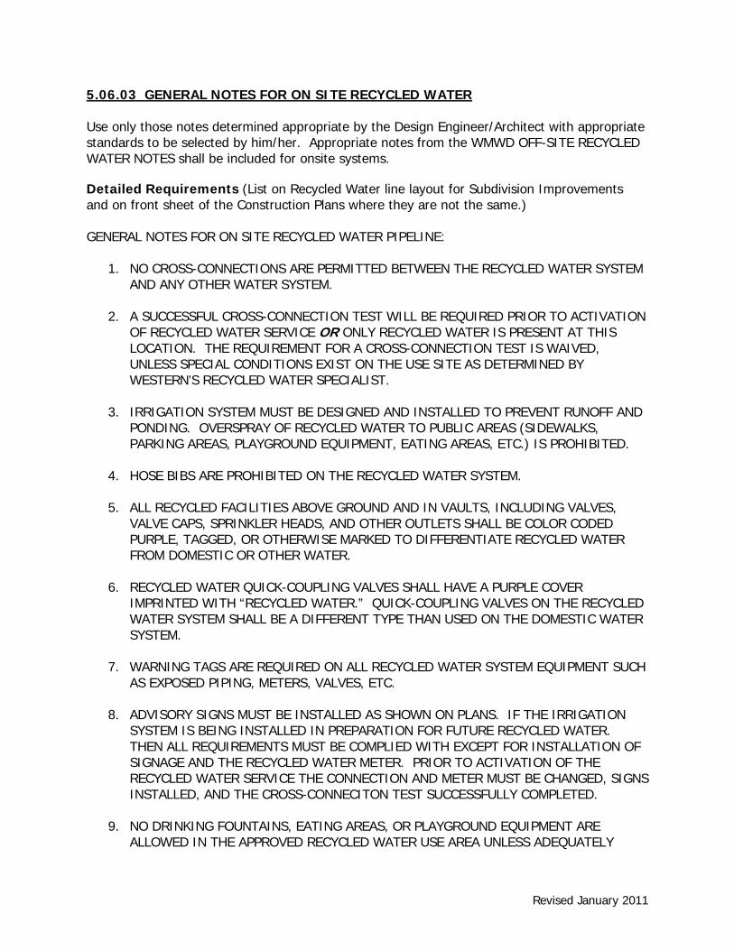
5.06.03 GENERAL NOTES FOR ON SITE RECYCLED WATER Use only those notes determined appropriate by the Design Engineer/Architect with appropriate standards to be selected by him/her. Appropriate notes from the WMWD OFF-SITE RECYCLED WATER NOTES shall be included for onsite systems. Detailed Requirements (List on Recycled Water line layout for Subdivision Improvements and on front sheet of the Construction Plans where they are not the same.) GENERAL NOTES FOR ON SITE RECYCLED WATER PIPELINE:
1. NO CROSS-CONNECTIONS ARE PERMITTED BETWEEN THE RECYCLED WATER SYSTEM AND ANY OTHER WATER SYSTEM.
2. A SUCCESSFUL CROSS-CONNECTION TEST WILL BE REQUIRED PRIOR TO ACTIVATION OF RECYCLED WATER SERVICE OR ONLY RECYCLED WATER IS PRESENT AT THIS LOCATION. THE REQUIREMENT FOR A CROSS-CONNECTION TEST IS WAIVED, UNLESS SPECIAL CONDITIONS EXIST ON THE USE SITE AS DETERMINED BY WESTERN’S RECYCLED WATER SPECIALIST.
3. IRRIGATION SYSTEM MUST BE DESIGNED AND INSTALLED TO PREVENT RUNOFF AND PONDING. OVERSPRAY OF RECYCLED WATER TO PUBLIC AREAS (SIDEWALKS, PARKING AREAS, PLAYGROUND EQUIPMENT, EATING AREAS, ETC.) IS PROHIBITED.
4. HOSE BIBS ARE PROHIBITED ON THE RECYCLED WATER SYSTEM.
5. ALL RECYCLED FACILITIES ABOVE GROUND AND IN VAULTS, INCLUDING VALVES, VALVE CAPS, SPRINKLER HEADS, AND OTHER OUTLETS SHALL BE COLOR CODED PURPLE, TAGGED, OR OTHERWISE MARKED TO DIFFERENTIATE RECYCLED WATER FROM DOMESTIC OR OTHER WATER.
6. RECYCLED WATER QUICK-COUPLING VALVES SHALL HAVE A PURPLE COVER IMPRINTED WITH “RECYCLED WATER.” QUICK-COUPLING VALVES ON THE RECYCLED WATER SYSTEM SHALL BE A DIFFERENT TYPE THAN USED ON THE DOMESTIC WATER SYSTEM.
7. WARNING TAGS ARE REQUIRED ON ALL RECYCLED WATER SYSTEM EQUIPMENT SUCH AS EXPOSED PIPING, METERS, VALVES, ETC.
8. ADVISORY SIGNS MUST BE INSTALLED AS SHOWN ON PLANS. IF THE IRRIGATION SYSTEM IS BEING INSTALLED IN PREPARATION FOR FUTURE RECYCLED WATER. THEN ALL REQUIREMENTS MUST BE COMPLIED WITH EXCEPT FOR INSTALLATION OF SIGNAGE AND THE RECYCLED WATER METER. PRIOR TO ACTIVATION OF THE RECYCLED WATER SERVICE THE CONNECTION AND METER MUST BE CHANGED, SIGNS INSTALLED, AND THE CROSS-CONNECITON TEST SUCCESSFULLY COMPLETED.
9. NO DRINKING FOUNTAINS, EATING AREAS, OR PLAYGROUND EQUIPMENT ARE ALLOWED IN THE APPROVED RECYCLED WATER USE AREA UNLESS ADEQUATELY
Revised January 2011
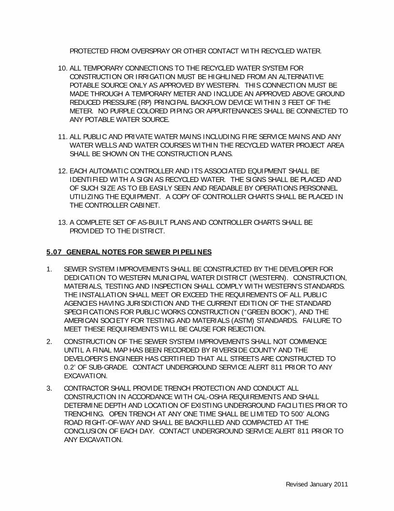
PROTECTED FROM OVERSPRAY OR OTHER CONTACT WITH RECYCLED WATER.
10. ALL TEMPORARY CONNECTIONS TO THE RECYCLED WATER SYSTEM FOR CONSTRUCTION OR IRRIGATION MUST BE HIGHLINED FROM AN ALTERNATIVE POTABLE SOURCE ONLY AS APPROVED BY WESTERN. THIS CONNECTION MUST BE MADE THROUGH A TEMPORARY METER AND INCLUDE AN APPROVED ABOVE GROUND REDUCED PRESSURE (RP) PRINCIPAL BACKFLOW DEVICE WITHIN 3 FEET OF THE METER. NO PURPLE COLORED PIPING OR APPURTENANCES SHALL BE CONNECTED TO ANY POTABLE WATER SOURCE.
11. ALL PUBLIC AND PRIVATE WATER MAINS INCLUDING FIRE SERVICE MAINS AND ANY WATER WELLS AND WATER COURSES WITHIN THE RECYCLED WATER PROJECT AREA SHALL BE SHOWN ON THE CONSTRUCTION PLANS.
12. EACH AUTOMATIC CONTROLLER AND ITS ASSOCIATED EQUIPMENT SHALL BE IDENTIFIED WITH A SIGN AS RECYCLED WATER. THE SIGNS SHALL BE PLACED AND OF SUCH SIZE AS TO EB EASILY SEEN AND READABLE BY OPERATIONS PERSONNEL UTILIZING THE EQUIPMENT. A COPY OF CONTROLLER CHARTS SHALL BE PLACED IN THE CONTROLLER CABINET.
13. A COMPLETE SET OF AS-BUILT PLANS AND CONTROLLER CHARTS SHALL BE PROVIDED TO THE DISTRICT.
5.07 GENERAL NOTES FOR SEWER PIPELINES 1. SEWER SYSTEM IMPROVEMENTS SHALL BE CONSTRUCTED BY THE DEVELOPER FOR
DEDICATION TO WESTERN MUNICIPAL WATER DISTRICT (WESTERN). CONSTRUCTION, MATERIALS, TESTING AND INSPECTION SHALL COMPLY WITH WESTERN’S STANDARDS. THE INSTALLATION SHALL MEET OR EXCEED THE REQUIREMENTS OF ALL PUBLIC AGENCIES HAVING JURISDICTION AND THE CURRENT EDITION OF THE STANDARD SPECIFICATIONS FOR PUBLIC WORKS CONSTRUCTION (“GREEN BOOK”), AND THE AMERICAN SOCIETY FOR TESTING AND MATERIALS (ASTM) STANDARDS. FAILURE TO MEET THESE REQUIREMENTS WILL BE CAUSE FOR REJECTION.
2. CONSTRUCTION OF THE SEWER SYSTEM IMPROVEMENTS SHALL NOT COMMENCE UNTIL A FINAL MAP HAS BEEN RECORDED BY RIVERSIDE COUNTY AND THE DEVELOPER’S ENGINEER HAS CERTIFIED THAT ALL STREETS ARE CONSTRUCTED TO 0.2’ OF SUB-GRADE. CONTACT UNDERGROUND SERVICE ALERT 811 PRIOR TO ANY EXCAVATION.
3. CONTRACTOR SHALL PROVIDE TRENCH PROTECTION AND CONDUCT ALL CONSTRUCTION IN ACCORDANCE WITH CAL-OSHA REQUIREMENTS AND SHALL DETERMINE DEPTH AND LOCATION OF EXISTING UNDERGROUND FACILITIES PRIOR TO TRENCHING. OPEN TRENCH AT ANY ONE TIME SHALL BE LIMITED TO 500’ ALONG ROAD RIGHT-OF-WAY AND SHALL BE BACKFILLED AND COMPACTED AT THE CONCLUSION OF EACH DAY. CONTACT UNDERGROUND SERVICE ALERT 811 PRIOR TO ANY EXCAVATION.

Revised January 2011
4. PIPE SHALL BE HANDLED SO AS TO PROTECT PIPE AT ALL TIMES AND SHALL BE CAREFULLY BEDDED TO PROVIDE CONTINUOUS BEARING AND TO PREVENT UNEVEN SETTLEMENT. PIPE SHALL BE PROTECTED AGAINST FLOTATION AT ALL TIMES. OPEN ENDS OF INSTALLED SEWER PIPE SHALL BE SEALED AT ALL TIMES WHEN CONSTRUCTION IS NOT IN PROGRESS.
5. PIPE JOINTS SHALL NOT BE DEFLECTED AT ANY ANGLE GREATER THAN THE MAXIMUM ANGLE RECOMMENDED BY THE PIPE MANUFACTURER.
6. CONNECTIONS TO EXISTING WESTERN SEWER PIPELINES SHALL NOT BE ACCOMPLISHED UNLESS WESTERN’S INSPECTOR IS PRESENT. WESTERN MAY ELECT TO MAKE THE CONNECTION AT THE DEVELOPER’S EXPENSE. CONTRACTOR SHALL FIELD VERIFY BOTH HORIZONTAL AND VERTICAL LOCATIONS OF EXISTING SEWER PIPELINES PRIOR TO CONSTRUCTION.
7. BACKFILL SHALL BE COMPACTED TO EITHER 90% RELATIVE DENSITY OR IN ACCORDANCE WITH THE REQUIREMENTS OF THE AGENCY HAVING JURISDICTION, WHICHEVER IS MORE STRINGENT.
8. SEWER LATERALS SHALL BE 4” PVC UNLESS OTHERWISE INDICATED. EXACT LOCATIONS OF WYES AND LATERALS SHALL BE ESTABLISHED IN THE FIELD PRIOR TO INSTALLATION. AN “S” SHALL BE IMPRINTED ON THE CURB FACE AT EACH SERVICE LATERAL LOCATION AND A STEEL ROD OR STAKE SHALL BE INSTALLED AT THE END OF EACH SEWER LATERAL TO ASSIST IN LOCATING AT A LATER DATE.
9. A 2” WIDE METALLIC LOCATOR TAPE SHALL BE PLACED WITH EACH SEWER AND SERVICE LATERAL TO ASSIST WITH FUTURE LOCATION. TAPE SHALL BE PLACED AT LEAST 6” ABOVE THE PIPE BUT NOT DEEPER THAN 4’ FROM THE PROPOSED FINISHED GRADE.
10. ALL SEWERS SHALL BE CLEANED, AIR TESTED AND VIDEO INSPECTED PRIOR TO ACCEPTANCE BY WESTERN.
11. SURFACE IMPROVEMENTS DAMAGED BY THE CONTRACTOR’S OPERATIONS SHALL BE RECONSTRUCTED BY THE CONTRACTOR TO THE REQUIREMENTS OF THE AGENCY (CITY OR COUNTY) HAVING JURISDICTION.
12. THE DEVELOPER SHALL PROVIDE ONE SET OF PRINTS SHOWING ALL “AS-BUILT” CONDITIONS INCLUDING THE STATIONING OF SEWER LATERAL CONNECTIONS AND PAD ELEVATIONS, AS A CONDITION OF FINAL APPROVAL.
13. ANY REVISION TO THESE DRAWINGS MUST BE APPROVED IN WRITING BY WESTERN.
14. THE DEVELOPER SHALL INSTALL BACKWATER VALVES, WHERE REQUIRED, PER THE CURRENT EDITION OF THE UNIFORM PLUMBING CODE AND PER WESTERN’S STANDARDS.
15. THE CONTRACTOR IS ADVISED THAT THE WORK ON THIS PROJECT MAY INVOLVE WORKING IN A CONFINED AIR SPACE. CONTRACTOR SHALL BE RESPONSIBLE FOR COMPLIANCE WITH “CONFINED AIR SPACE” ARTICLE 108, TITLE 8 CALIFORNIA ADMINISTRATIVE CODE OF REGULATIONS.
16. PRIOR TO CONSTRUCTION THE CONTRACTOR SHALL POTHOLE ALL UTILITY CROSSINGS AND CONNECTIONS AND VERIFY THE LOCATION AND ELEVATION OF ALL UTILITIES

Revised January 2011
AFFECTED. THE ENGINEER SHALL BE NOTIFIED OF ANY DISCREPANCIES BEFORE CONSTRUCTION BEGINS.
17. CONTRACTOR SHALL WARRANTY ALL WORK FOR 12 MONTHS AFTER DATE OF FINAL INSPECTION.
18. CONTRACTOR SHALL CALL FOR INSPECTION WHEN NEEDED – 48 HOURS MINIMUM ADVANCED NOTIFICATION PRIOR TO INSPECTION AND/OR TESTING.

Revised January 2011
5.08 WATER PLAN - CHECKLISTS 5.08.01 WATER COVER SHEET CHECKLIST
WESTERN MUNICIPAL WATER DISTRICT
PROJECT:___________________________________ DATE:_____________________
WATER PIPELINE COVER SHEET CHECKLIST
WATER
STANDARD WMWD TITLE BLOCK
GENERAL WATER NOTES
LEGEND NUMBERED CONSTRUCTION NOTES AND ESTIMATE OF QUANTITIES
WATER CERTIFICATION
INDEX OF DRAWINGS
VICINITY AND LOCATION MAP
Scale
North Arrow
Street Names
Section, Township, and Range
INDEX MAP
Scale (1”=100’ or 1”=400’)
North Arrow
Street Names
Lot Numbers
Pad Elevations
Pressure Zone, Highest & Lowest Pad Elevation
Proposed Water Lines (diameter and materials)
Fire Hydrants
Air Valves
Blowoffs
Tees, Crosses
Valves
Water Services
Plan Layout/Sheet Reference
Revised January 2011
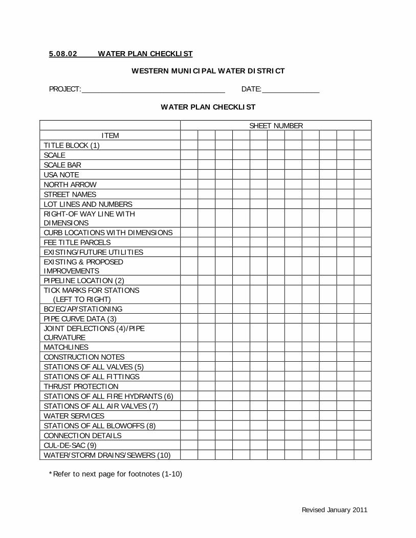
5.08.02 WATER PLAN CHECKLIST
WESTERN MUNICIPAL WATER DISTRICT
PROJECT:___________________________________ DATE:______________
WATER PLAN CHECKLIST
SHEET NUMBER ITEM
TITLE BLOCK (1) SCALE SCALE BAR USA NOTE NORTH ARROW STREET NAMES LOT LINES AND NUMBERS RIGHT-OF WAY LINE WITH DIMENSIONS
CURB LOCATIONS WITH DIMENSIONS FEE TITLE PARCELS EXISTING/FUTURE UTILITIES EXISTING & PROPOSED IMPROVEMENTS
PIPELINE LOCATION (2) TICK MARKS FOR STATIONS (LEFT TO RIGHT)
BC/EC/AP/STATIONING PIPE CURVE DATA (3) JOINT DEFLECTIONS (4)/PIPE CURVATURE
MATCHLINES CONSTRUCTION NOTES STATIONS OF ALL VALVES (5) STATIONS OF ALL FITTINGS THRUST PROTECTION STATIONS OF ALL FIRE HYDRANTS (6) STATIONS OF ALL AIR VALVES (7) WATER SERVICES STATIONS OF ALL BLOWOFFS (8) CONNECTION DETAILS CUL-DE-SAC (9) WATER/STORM DRAINS/SEWERS (10)
*Refer to next page for footnotes (1-10)
Revised January 2011
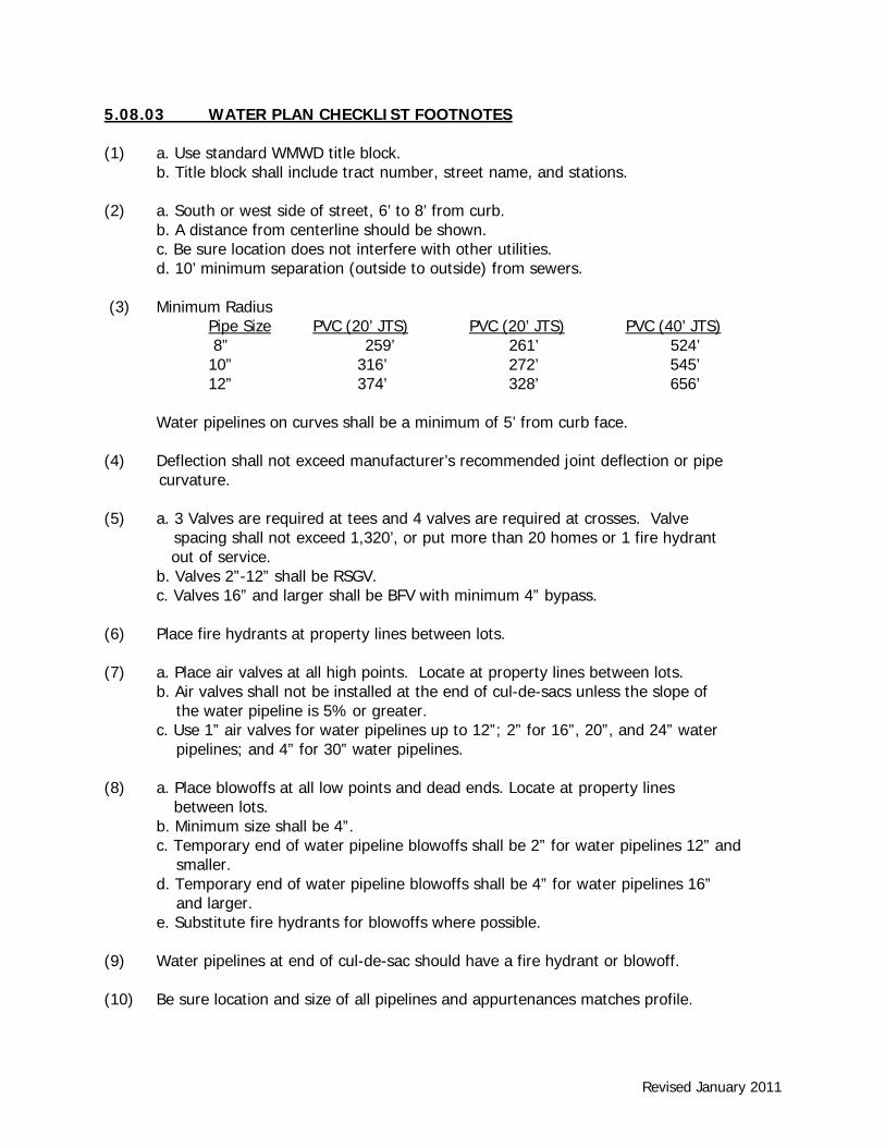
5.08.03 WATER PLAN CHECKLIST FOOTNOTES (1) a. Use standard WMWD title block. b. Title block shall include tract number, street name, and stations. (2) a. South or west side of street, 6’ to 8’ from curb. b. A distance from centerline should be shown. c. Be sure location does not interfere with other utilities.
d. 10’ minimum separation (outside to outside) from sewers.
(3) Minimum Radius Pipe Size PVC (20’ JTS) PVC (20’ JTS) PVC (40’ JTS) 8” 259’ 261’ 524’ 10” 316’ 272’ 545’ 12” 374’ 328’ 656’
Water pipelines on curves shall be a minimum of 5’ from curb face.
(4) Deflection shall not exceed manufacturer’s recommended joint deflection or pipe curvature.
(5) a. 3 Valves are required at tees and 4 valves are required at crosses. Valve spacing shall not exceed 1,320’, or put more than 20 homes or 1 fire hydrant
out of service. b. Valves 2”-12” shall be RSGV.
c. Valves 16” and larger shall be BFV with minimum 4” bypass. (6) Place fire hydrants at property lines between lots. (7) a. Place air valves at all high points. Locate at property lines between lots.
b. Air valves shall not be installed at the end of cul-de-sacs unless the slope of the water pipeline is 5% or greater. c. Use 1” air valves for water pipelines up to 12”; 2” for 16”, 20”, and 24” water pipelines; and 4” for 30” water pipelines.
(8) a. Place blowoffs at all low points and dead ends. Locate at property lines between lots. b. Minimum size shall be 4”.
c. Temporary end of water pipeline blowoffs shall be 2” for water pipelines 12” and smaller. d. Temporary end of water pipeline blowoffs shall be 4” for water pipelines 16” and larger.
e. Substitute fire hydrants for blowoffs where possible. (9) Water pipelines at end of cul-de-sac should have a fire hydrant or blowoff. (10) Be sure location and size of all pipelines and appurtenances matches profile.

Revised January 2011
5.08.04 WATER PROFILE CHECKLIST
WESTERN MUNICIPAL WATER DISTRICT
PROJECT:________________________ DATE:____________
WATER PROFILE CHECKLIST
SHEET NUMBER
ITEM
STATION AT BOTTOM PROFILE GRID
ELEVATIONS ON BOTH SIDES OF GRID
EXISTING/PROPOSED GROUND SURFACE
MATCHLINES
PIPE MATERIAL AND SIZE OF WATER PIPELINE (LABEL AT TOP OF GRID) SHOW LIMITS
STATIONS, DISTANCE, AND SLOPES (1)
STATION FOR ALL FITTINGS AND APPURTENANCES (2)
PIPE COVER (3)
UTILITIES (4)
PIPE LENGTH AT TOP OF PROFILE (5)
(1) Show station and flow line elevation at each grade break.
Minimum slope = 0.0050 Indicate slope to 4 decimal places and + or – (e.g.+ 0.0075)
(2) Show station and flow line elevations for each tee, cross, air valve, and blowoff. Show station of fire hydrants but not flow line elevations unless fire hydrant is a blowoff.
(3) Cover for 8” diameter water pipelines shall be 3’. Cover for water pipelines 12” diameter and larger shall be 4’. In no case shall pipeline depth to top of pipe be greater than 60” without written Western approval.
(4) a. A minimum clearance of 1’ is required for all utilities. b. Water pipelines shall not cross under sewers or storm drains. Exceptions require
Western approval. c. Where water pipelines cross over utilities with a clearance of 2’ or less, show elevation
for top of utility and bottom of water pipeline. Where water pipelines cross under utilities with a clearance of 2’ or less, show elevation for top of water pipeline and bottom of utility.
(5) Use actual water pipeline length.

Revised January 2011
5.09 SEWER PLAN - CHECKLISTS 5.09.01 SEWER COVER SHEET CHECKLIST
WESTERN MUNICIPAL WATER DISTRICT
PROJECT:_________________________ DATE:____________
SEWER COVER SHEET CHECKLIST
SEWER
STANDARD WMWD TITLE BLOCK
GENERAL SEWER NOTES
LEGEND
NUMBERED CONSTRUCTION NOTES AND ESTIMATE OF QUANTITIES
SEWER CERTIFICATION
INDEX OF DRAWINGS
VICINITY AND LOCATION MAP
Scale
North Arrow
Street Names
Section, Township, and Range
INDEX MAP
Scale (1”=100’ or 1”=400’)
North Arrow
Street Names
Lot Numbers
Pad Elevations
Proposed Sewer Lines (diameter and materials)
Manholes
Sewer Laterals
Backwater Valves
Plan Layout/Sheet Reference

Revised January 2011
5.09.02 SEWER PLAN CHECKLIST
WESTERN MUNICIPAL WATER DISTRICT
PROJECT:______________________________________
DATE:_________________________________________
SEWER PLAN CHECKLIST
SHEET NUMBER ITEM
TITLE BLOCK (1) SCALE SCALE BAR USA NOTE NORTH ARROW STREET NAMES LOT LINES AND NUMBERS RIGHT-OF WAY LINE WITH DIMENSIONS
CURB LOCATIONS WITH DIMENSIONS
FEE TITLE PARCELS EXISTING/FUTURE UTILITIES EXISTING & PROPOSED IMPROVEMENTS
SEWER LOCATION (2) TICK MARKS FOR STATIONS (LEFT TO RIGHT)
BC/EC/AP/STATIONING CURVE DATA MATCHLINES CONSTRUCTION NOTES STATIONS OF ALL MANHOLES (3) SEWER LATERALS (4) BACKWATER VALVES (5) CONNECTION DETAILS SEWER/STORM DRAIN/WATER (6) *Refer to next page for footnotes (1-6)
Revised January 2011
5.09.02 SEWER PLAN CHECKLIST (CONTINUED)
WESTERN MUNICIPAL WATER DISTRICT SEWER IMPROVEMENT PLAN CHECKLIST FOOTNOTES
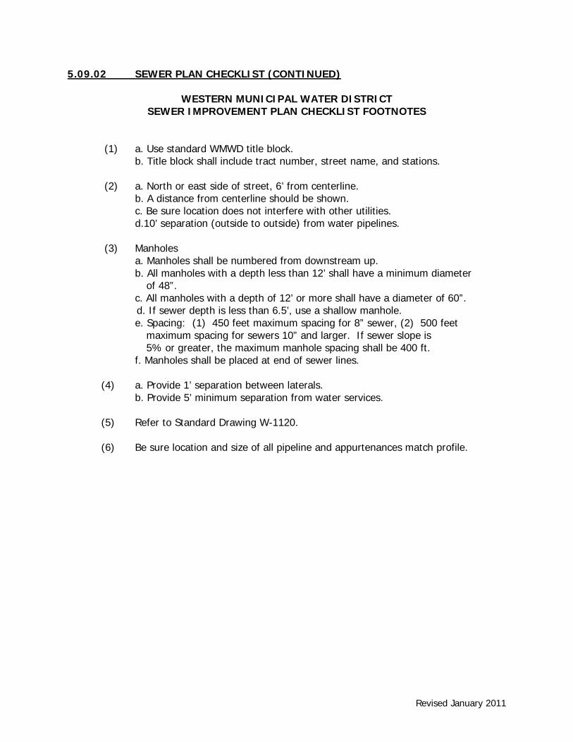
(1) a. Use standard WMWD title block. b. Title block shall include tract number, street name, and stations.
(2) a. North or east side of street, 6’ from centerline. b. A distance from centerline should be shown. c. Be sure location does not interfere with other utilities. d.10’ separation (outside to outside) from water pipelines. (3) Manholes a. Manholes shall be numbered from downstream up.
b. All manholes with a depth less than 12’ shall have a minimum diameter of 48”.
c. All manholes with a depth of 12’ or more shall have a diameter of 60”. d. If sewer depth is less than 6.5’, use a shallow manhole.
e. Spacing: (1) 450 feet maximum spacing for 8” sewer, (2) 500 feet maximum spacing for sewers 10” and larger. If sewer slope is 5% or greater, the maximum manhole spacing shall be 400 ft. f. Manholes shall be placed at end of sewer lines.
(4) a. Provide 1’ separation between laterals.
b. Provide 5’ minimum separation from water services.
(5) Refer to Standard Drawing W-1120.
(6) Be sure location and size of all pipeline and appurtenances match profile.

Revised January 2011
5.09.03 SEWER PROFILE CHECKLIST
WESTERN MUNICIPAL WATER DISTRICT SEWER PROFILE CHECKLIST
PROJECT:___________________________ DATE:___________
SHEET NUMBER ITEM
STATION AT BOTTOM OF PROFILE GRID ELEVATIONS ON BOTH SIDES OF GRIDS EXISTING/PROPOSED GROUND SURFACE MATCHLINES PIPE SIZE, MATERIAL, AND LENGTH STATIONS, DISTANCE, AND SLOPES (1) PIPE COVER (2) STATIONS FOR ALL APPURTENANCES UTILITIES (3)
(1) a. Minimum slope
Pipe Diameter (in.) Min. Slope (V=2 fps)
Max Slope (V=10 fps)
8 0.00340 0.086 10 0.00260 0.061 12 0.00200 0.049
Slopes should be set to 2 decimal figures, evenly divisible by 4, where possible.
b. Show sewer flow line elevations at inlet and outlet of each manhole. c. 0.2’ drop across manholes for straight-runs. 0.2’ drop for 90 bends. d. At junctions, the tops of sewers shall match. e. Vertical curves are not allowed. Vertical curves are not permitted within sewer systems except when approved by Western. Application for exceptions shall be submitted in writing prior to plan check submittal and include justification.
(2) a. Minimum 7’ cover over top of pipe; depth to flow line is typically 7.5’.
b. If depth is greater than 12’, use 60” diameter manholes. c. If sewer depth is less than 6.5’, use a shallow manhole.
(3) a. A minimum clearance of 1’ is required for all.
b. Sewers shall not cross over water pipelines. Requires Western approval. c. Where sewers cross over utilities with a clearance of 2’ or less, show
elevation for top of utility and bottom of sewer. Where sewers crosses under utilities with a clearance of 2’ or less, show elevation for top of sewer and bottom of utility.

Revised January 2011
5.10 ELECTRONIC PLAN SUBMITTAL Western requires the Developer’s engineer preparing the improvement plans to submit ONE composite/ overall map in plan view showing the description and layers listed below in item number 1 in digital format. No individual plan and profile sheets. THIS IS NOT AN OPTIONAL ITEM. The graphics file must contain water and/or sewer pipelines, improvement area boundary, street centerline, right-of-way and lot/parcel line data to facilitate transferring the information into Western’s mapping system. The digital drawing shall be at a 1:1 scale. If the engineer does not have the capability to provide such files, Western will input the improvement information into the mapping system and recover the costs from the Developer prior to final acceptance of the improvements through the plan check process. Receipt and acceptance of the digital data is a plan check requirement prior to Western signing the improvement plans.
1. Tract Development Digital Layering Scheme Note: Please submit the listed layers ONLY.
Description Layer Name
Color
Line Type
Text Height
Easement (or Fee Title) ESMNT Magenta Continuous *8.0 Easement Right-of-Way ESMTRW Magenta Dashed - Lot number LOT 80 Continuous *7.0 Property line PL 8 Continuous - Right-of-Way RW White Continuous - Sewer Lateral SLAT 80 Continuous - Sewer Manhole SMH 80 Continuous - Sewer pipeline SEWER 90 Continuous - Sewer pipeline material SPM White Continuous *7.0 Sewer pipeline size SPS White Continuous *7.0 Street centerline CTRL Red Dash-dot - Street name STNAME White Continuous *12.0 Symbols SYM 8 Continuous - Water Lateral LAT Red Continuous - Water pipeline WATER 160 Continuous - Water pipeline material PM Blue Continuous *7.0 Water pipeline size PS Blue Continuous *7.0
*Text style is to be “standard” font. 2. Data Integrity
a. A tie to a known location point is required, such as a quarter section, street intersection, etc.
b. The tie coordinates shall be based on the California State Plane Coordinate system (NAD 83 and Zone VI) in at least two locations, preferably on opposite sides of the area being mapped.
Revised January 2011
3. Software Format
The acceptable format for digital submissions shall be one of the following: AutoCAD’s Release 2004 (.DWG) or an earlier version Drawing Exchange File (.DXF) Shape File (.SHP)
4. Digital Data Media
All digital information shall be submitted to Western on one of the following: CD Rom/DVD Rom
The digital data shall be submitted prior to Western signing the plans.
The following information must be submitted with all digital data:
DATE (Date submitted) MAP NAME (TR, PM, PP, Etc.) WMWD WO# (WMWD will complete this) COMPANY (Engineering Firm Name) MEDIA CREATOR (Name of person creating media) FILE NAME (Filename with extension)
5. Requirements For Hardcopy Submission
In conjunction with the digital submission of the proposed improvement a printed overall layout of the information will be required.
The scale for this plan shall be either 1”=100’, 1”=200’, or 1”=400’, whichever best fits a D-size (24” x 36”) drawing sheet.
6. Symbol Representation
All water and sewer symbols shall conform to Western’s AutoCAD map symbols. Western will provide these symbols in .DWG or .DXF formats on a diskette or via e-mail.
Revised January 2011
5.11 COMMERCIAL PLAN CHECK PACKAGE Please reference separate
COMMERCIAL PLAN
CHECK PACKAGE