Embed Size (px)
Citation preview

1 / 34
Developer Guide
V1.0.4
Oct. 2017

2 / 34
Contents
SAFETY INSTRUCTIONS ................................................................................................................................................ 3
GENERAL INFORMATION .............................................................................................................................................. 4
1.SOURCE FILE .................................................................................................................................................................. 4
2.REFERENCE FRAME ......................................................................................................................................................... 4
3.COORDINATE ................................................................................................................................................................ 5
4.MOUNTING ................................................................................................................................................................... 6
5. BUTTONS & INDICATOR LIGHTS ...................................................................................................................................... 8
6.EXTENSION DESCRIPTION ................................................................................................................................................ 9
SPECIFICATIONS .......................................................................................................................................................... 10
APPLICATION INFORMATION ..................................................................................................................................... 12
1.SEND COMMAND OVER USB CABLE ............................................................................................................................... 12
2.SEND COMMAND OVER BLUETOOTH .............................................................................................................................. 14
3.THE 2ND
UART ........................................................................................................................................................... 17
4.ARDUINO.................................................................................................................................................................... 18
5.ROS & PYTHON .......................................................................................................................................................... 20
6.OPENMV DEMO ......................................................................................................................................................... 20
6.RECOVER FROM THE WRONG CODE ............................................................................................................................... 21
PROTOCOL .................................................................................................................................................................... 22
1.INTRODUCTION ............................................................................................................................................................ 22
2.EXAMPLE .................................................................................................................................................................... 22
3.COMMANDS(TBD)·...................................................................................................................................................... 22
UARM COMMUNITY ...................................................................................................................................................... 33
RELEASE NOTE ............................................................................................................................................................ 34

3 / 34
Safety Instructions
1. Please don’t put your hands between the arms when uArm is moving.
2. Please use the official power supply for safety reasons.
3. Please clear a space for uArm, in case of knocking down anything.

4 / 34
General Information
General information for the robot arm, and it’s good to know before
developing.
1.Source file
Source code of Firmware for Swift Pro:
https://github.com/uArm-Developer/SwiftProForArduino
Source code of ROS for Swift Pro:
https://github.com/uArm-Developer/SwiftproForROS
Python library for Swift Pro:
https://github.com/uArm-Developer/pyuf
OpenMV example for tracking:
https://github.com/uArm-Developer/OpenMV-Examples
To be continued…(Arduino, C++, Raspberry Pi)
2.Reference Frame
(Right Motor)
(Left Motor)
(Base Motor)

5 / 34
3.Coordinate
(The picture in the right also shows the dynamic payload range of uArm.
Test condition: G2202 F1000; Red point is the Tool Center Point.)
Detail size of each arm and base.
Origin of Base
Coordinate (0,0,0)

6 / 34
The origin of base coordinate is in the center of the base. But the tool center
point is different for different end-effectors. And we also offer the different
commands for different usages.
Suction Laser Hot End Universal Holder
Currently we offer 4 kinds of mode:
M2400 S0 : Normal mode (end-effector tools: suction)
M2400 S1 : Laser mode (end-effector tools: laser)
M2400 S2 : 3D printing mode (end-effector tools: Hot End)
M2400 S3 : Universal holder mode (end-effector tools: universal holder)
For the gripper, there is no special mode since gripper has the fingers and can rotate
horizontally.
4.Mounting
Position of Tool Center Point for each End-effectors
PEN

7 / 34
8 / 34
5. Buttons & Indicator Lights
Caution: By default, the user defined button is for switching between Bluetooth and USB mode.
Please ensure the button is UP while communicating with uArm via USB.

9 / 34
6.Extension Description
Details of 30P Base Extension

10 / 34
Specifications
Specifications
Weight 2.2kg
Degrees of Freedom 4
Repeatability 0.2mm
Max. Payload 500g
Working Range 50mm~320mm
Max. Speed 100mm/s
Connector Micro USB
Wireless Bluetooth 4.0
Input Voltage DC 12V
Power Adapter Input:100~240V 50/60Hz; Output: 12V5A 60W
Operation Temperature &
Humidity
0℃-35℃ 30%RH-80%RH
noncondensing
Storage Temperature &
Humidity
-20℃-60℃ 30%RH-80%RH
noncondensing
Hardware
Joint Type Customized Gearbox + Stepper
Position Feedback 12 bit Encoder
Reducer Customized ultra-thin Gearbox
Dimension(L*W*H) 150mm*140mm*281mm
Mother Board Arduino MEGA 2560
Material Aluminum
Baud Rate 115200bps
Extendable I/O Interface I/O *27,IIC *1,5V*1,12V*1,Stepper*1
Software
PC Control uArm Studio
App Control uArm Play
For Developer Python/Arduino/ROS
Feature Open Source
Joint Speed & Torque
Speed Lifetime Torque
Base Motor 40°/s >3000h 12kg⋅cm
Left Motor 40°/s >3000h 12kg⋅cm
Right Motor 40°/s >3000h 12kg⋅cm
End-effector Motor 60°/s 500h 2kg⋅cm

11 / 34
Accessories
Pump
Suction Diameter 5mm~10mm
Max. Pressure 33kPa
Max. Lifting Weight 1000g
Feature With feedback
Universal Holder
Weight 36g
Dimension(L*W*H) 62mm*25mm*15mm
Material Aluminum
Holder Diameter 14mm
Gripper
Weight 58g
Dimension(L*W*H) 92mm*50mm*18mm
Material Aluminum
Max. Force 750~800g
Max. Size of Object 40mm
Max. Speed 20mm/s
Drive Mode Electrically-driven
Working Voltage/Current 6V/300mA
OpenMV Camera
Focal Length 2.8mm
FOV 115°
F-number f2.0
Programmable Method Micro Python
Weight 16g
Dimension(L*W*H) 45mm*36mm*30mm
3D Printing Kit
Type E3D v6
Consumption 35W
Nozzle Diameter 0.4mm
Max Temp 270 ℃
Material PLA
Max. Printing Speed 20mm/s
File Format .gcode
Printing Size(L*W*H) 10mm*10mm*10mm
Laser Engraving Kit
Laser Power 500mW
Working Voltage/Current 12V/5A
Wave Length 405nm
Weight 140g
Dimension(L*W*H) 55mm*33mm*88mm
Materials to Engrave Wood, Plastic, Leather, Feather,
Paper, etc.

12 / 34
Application Information
We would introduce several ways to play with the robot arm in different platform.
1.Send Command over USB Cable
Power on the uArm and open the Arduino IDE. And setting the board like the picture below.
Please make sure the port you are choosing is the correct port of uArm.
Open the serial monitor in the right side of Arduino IDE. After clicking, and you could hear
a beep which means the uArm is connected.

13 / 34
Set the parameter of serial monitor in the right bottom. If the setting is correct, you would
receive the detail information from uArm like the picture below.
Now, you are able to send the command to the uArm. Let’s send “G0 X250 Y0 Z130
F10000”.

14 / 34
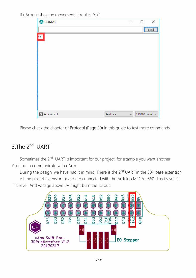
If uArm finishes the movement, it replies “ok”.
Please check the chapter of Protocol (Page 20) in this guide to test more commands.
2.Send Command over Bluetooth
Plug in the Bluetooth stick. And press down the button beside the power button.
Power on the uArm. When the Bluetooth stick is searching, the blue indicator keeps blink
until the wireless connection is built up between stick and uArm. And the blue indicators in both
stick and uArm become solid.

15 / 34
Open the Arduino IDE. And setting the COM port like the picture below. Please make sure
the port you are choosing is the correct port of Bluetooth stick.
(Driver of stick: http://www.ftdichip.com/Drivers/VCP.htm )
Open the serial monitor in the right side of Arduino IDE. After clicking, and you could hear
a beep which means the uArm is connected.

16 / 34
Set the parameter of serial monitor in the right bottom like the picture below.
Now, you are able to send the command to the uArm. Let’s send “G0 X250 Y0 Z130
F10000”.
17 / 34
If uArm finishes the movement, it replies “ok”.
Please check the chapter of Protocol (Page 20) in this guide to test more commands.
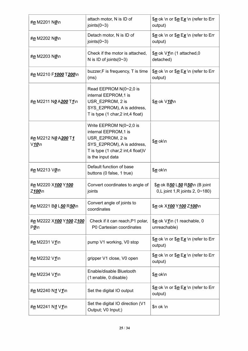
3.The 2nd UART
Sometimes the 2nd UART is important for our project, for example you want another
Arduino to communicate with uArm.
During the design, we have had it in mind. There is the 2nd UART in the 30P base extension.
All the pins of extension board are connected with the Arduino MEGA 2560 directly so it’s
TTL level. And voltage above 5V might burn the IO out.

18 / 34
So wiring the UART with the jump wire and also the GND. Then the hardware set up is
finished. Then we have to change the main communication port from USB to the 2nd UART port,
since the code only supports one port to deal with the command.
Sending “#0 M2500” command over USB cable to switch the port, and there are several
point you should know:
1. The port will be switched immediately (both ports receive the reply “ok”), and the USB port
can not be used as the communication port any more, only 2nd UART port would work for
sending Gcode.
2. There is no way to switch port any more, the only way to use USB port is reset the system
by power button.
If it’s not convenient for your project, please try to modify the source code following the
steps below:
1. Download the Arduino source file in Github.
2. Find the file named uArmSerial.cpp and modify the code in line 16 from _serial=&serial; to
_serial=&serial2; .
3. Find the file named uArmService.cpp and modify the code in line 693 from
commSerial.setSerialPort(&Serial); to commSerial.setSerialPort(&Serial2); .
4. Rebuild the files and download the code to uArm.
4.Arduino
The main code is written by Arduino IDE. Please check the link below:
https://github.com/uArm-Developer/SwiftProForArduino
How to compile and upload the file?
1. Download the code and extract it to your Arduino libraries folder (normally it’s in
C:/Users/ufactory/documents/Arduino/libraries/)

19 / 34
2. Find the file named Marlin.ino in the Marlin folder and open it
3. Plug in the USB cable and power port then turn on the power button

20 / 34
4. Select the correct port and type of Arduino board like the picture below
5. Click the upload button to finish the uploading
5.ROS & Python
Currently we released the library of Python and ROS. For more information please check the
link below.
Source code of ROS for Swift Pro:
https://github.com/uArm-Developer/SwiftproForROS
Python library for Swift Pro:
https://github.com/uArm-Developer/pyuf
6.OpenMV Demo
And also the demo of OpenMV:
https://github.com/uArm-Developer/OpenMV-Examples
You could find the details steps in quick start guide.

21 / 34
6.Recover from the Wrong Code
Sometimes you might want to go back to the official firmware and it’s too complicated to
download the Arduino source code and download it. Or you flashed bad code to the uArm and
you can’t even run it. Please try the offline flash tool here :
https://drive.google.com/drive/u/0/folders/0B-L-tCvknXU9dDhfSGJwT1JDY1U

22 / 34
Protocol
1.Introduction
• uArm Gcode is an important part of the uArm software.
• Based on the standard gCode protocol, we add a new protocol head in
front of the gCode so that it can be more easily to use and debug.
• What’s more, it is designed to be compatible with the standard gCode. (We
offer the code of decode the standard gCode)
2.Example
• Sending command from PC
“#25 G0 X180 Y0 Z150 F5000”
//move to [180,0,150] with the speed 5000mm/min
• Reply from uArm “$25 ok”
3.Commands(TBD)·
Command can be divided into two parts:
Command with underline: it’s the new added protocol head.
• The command from PC starts with ‘#’, while the command from uArm
starts with’$’.
• And the data following the symbol decided by the PC, and the reply from
the uArm should have the same data which indicates it finish the

23 / 34
command. (In the example above, PC sends the command with ‘#25’ and
uArm replies the command with ’$25’)
Command without the underline: it’s the standard gCode.
Caution
1.There should be blank space between each parameter;
2.The letters in the command should be capitalized;

24 / 34
GCode Command (v1.2) Description Feedback
1. #n is used for the debug, if you don’t want to use it please remove it directly.
(For Example: G2202 N0 V90\n)
2. ‘\n’ is the symbol of line feed.
Moving Command (parameters are in underline)
#n G0 X100 Y100 Z100
F1000\n
Move to XYZ(mm), F is speed(mm/min)
$n ok \n or $n Ex \n (refer to Err
output)
#n G1 X100 Y100 Z100
F1000\n
After entering the laser mode (M2400 S1), command G1 means laser on, G0 means off.
$n ok \n or $n Ex \n (refer to Err
output)
#n G2004 P1000\n Delay microsecond $n ok \n
#n G2201 S100 R90 H80
F1000\n
Polar coordinates, S is
stretch(mm), R is
rotation(degree),H is
height(mm), F is
speed(mm/min)
$n ok \n or $n Ex \n (refer to Err
output)
#n G2202 N0 V90\n
Move the motor to the
position ,N is ID of
joints(0~3),V is angle(0~180)
$n ok \n or $n Ex \n (refer to Err
output)
#n G2204 X10 Y10 Z10
F1000\n Relative displacement
$n ok \n or $n Ex \n (refer to Err
output)
#n G2205 S10 R10 H10
F1000\n
Polar coordinates for relative
displacement
$n ok \n or $n Ex \n (refer to Err
output)
Setting Command (parameters are in underline)
#n M17\n Attach all the joint motors $n ok \n
#n M204 P200 T200
R200\n
Set accelerations and save
P = Printing moves
R = Extruder only (no X, Y, Z)
moves
T =Hot End Travel (non
printing) moves
$n ok \n
#n M2019\n Detach all the joint motors $n ok \n
#n M2120 V0.2\n
Set time cycle of feedback,
return Cartesian coordinates, V
is time(seconds) @3 X154.71 Y194.91 Z10.21\n
#n M2122 V1\n
Report (@9 V0) when stop.
V1: Enable
V0: Disable $n ok \n
25 / 34
#n M2201 N0\n attach motor, N is ID of
joints(0~3)
$n ok \n or $n Ex \n (refer to Err
output)
#n M2202 N0\n Detach motor, N is ID of
joints(0~3)
$n ok \n or $n Ex \n (refer to Err
output)
#n M2203 N0\n Check if the motor is attached,
N is ID of joints(0~3)
$n ok V1\n (1 attached,0
detached)
#n M2210 F1000 T200\n buzzer,F is frequency, T is time
(ms)
$n ok \n or $n Ex \n (refer to Err
output)
#n M2211 N0 A200 T1\n
Read EEPROM N(0~2,0 is
internal EEPROM,1 is
USR_E2PROM, 2 is
SYS_E2PROM), A is address,
T is type (1 char,2 int,4 float)
$n ok V10\n
#n M2212 N0 A200 T1
V10\n
Write EEPROM N(0~2,0 is
internal EEPROM,1 is
USR_E2PROM, 2 is
SYS_E2PROM), A is address,
T is type (1 char,2 int,4 float)V
is the input data
$n ok\n
#n M2213 V0\n Default function of base
buttons (0 false, 1 true) $n ok\n
#n M2220 X100 Y100
Z100\n
Convert coordinates to angle of
joints
$n ok B50 L50 R50\n (B joint
0,L joint 1,R joints 2, 0~180)
#n M2221 B0 L50 R50\n Convert angle of joints to
coordinates $n ok X100 Y100 Z100\n
#n M2222 X100 Y100 Z100
P0\n
Check if it can reach,P1 polar,
P0 Cartesian coordinates
$n ok V1\n (1 reachable, 0
unreachable)
#n M2231 V1\n pump V1 working, V0 stop $n ok \n or $n Ex \n (refer to Err
output)
#n M2232 V1\n gripper V1 close, V0 open $n ok \n or $n Ex \n (refer to Err
output)
#n M2234 V1\n Enable/disable Bluetooth
(1:enable, 0:disable) $n ok\n
#n M2240 N1 V1\n Set the digital IO output $n ok \n or $n Ex \n (refer to Err
output)
#n M2241 N1 V1\n Set the digital IO direction (V1
Output; V0 Input;) $n ok \n

26 / 34
#n M2245 Vbtname\n
Set the name of Bluetooth, 11
letters limited (Do not add #n in
this command)
$n ok \n
#n M2304 P0\n Please check the Grove
modules below
#n M2305 P0 N1\n Please check the Grove
modules below
#n M2306 P0 V1000\n Please check the Grove
modules below
#n M2307 P0 V1\n Please check the Grove
modules below
#n M2400 S0\n
Set the mode of arm (0:Normal
1:Laser 2:3D printing
3:Universal holder)
$n ok \n
#n M2401\n Set the current position into the
reference position $n ok \n
#n M2410\n Set the height zero point $n ok \n
#n M2411 S100\n Set the offset of end-effector
(mm) $n ok \n
#n M2500\n
Switch the uart0 to uart2 for
external TTL uart communication
(For example OpenMV)
$n ok \n
Querying Command (parameters are in underline)
#n P2200\n Get the current angle of joints $n ok B50 L50 R50\n
#n P2201\n Get the device name $n ok V3.2\n
#n P2202\n Get the hardware version $n ok V1.2\n
#n P2203\n Get the software version $n ok V3.2\n
#n P2204\n Get the API version $n ok V3.2\n
#n P2205\n Get the UID $n ok V0123456789AB\n
#n P2206 N0\n Get the angle of number 0 joint
(0~2)
$n ok V80\n
#n P2220\n Get current coordinates $n ok X100 Y100 Z100\n
#n P2221\n Get current polar coordinates $n ok S100 R90 H80\n

27 / 34
#n P2231\n Get the status of pump $n ok V1\n (0 stop, 1 working, 2
grabbing things)
#n P2232\n Get the status of gripper $n ok V1\n (0 stop, 1 working, 2
grabbing things)
#n P2233\n Get the status of limited switch $n ok V1 (1 triggered, 0
untriggered)
#n P2234\n Get the status of power
connection
$n ok V1 (1 connected, 0
unconnected)
#n P2240 N1\n Get the status of digital IO $n ok V1\n (1 High, 0 Low)
#n P2241 N1\n Get the status of analog IO $n ok V295\n (return the data of
ADC)
#n P2242\n Get the default value of
AS5600 in each joint $n ok B2401 L344 R1048\n
#n P2400\n Check current status $n ok V1\n (0: normal; 1: laser; 2:
3D printing; 3: Universal holder;)
Ticking feedback
@1 Ready
@3 Timed feedback , ”M2120”
@4 N0 V1\n
Report the button event.
N: 0 = Menu button, 1 = Play
button
V: 1 = Click, 2 = Long Press
@5 V1\n Report event of power
connection
@6 N0 V1\n Report event of limit switch in
end-effector
@7 temp error Temperature error in 3D
printing
@9 V0\n Stop movement
Err Output
E20 Command not exist
E21 Parameter error
E22 Address out of range
E23 Command buffer full
E24 Power unconnected

28 / 34
E25 Operation failure
Grove modules
Grove Num
Module Commands Description Support
Ports Return
1 Chainable RGB LED
#n M2304 P3\n Deinit 3, 4, 5 $n ok\n
#n M2305 P3 N1 V2\n Init Module 1 in Port 3. V is the number of LEDs chained.
3, 4, 5 $n ok\n or E25 init fail
#n M2307 P3 V0 R228 G128 B100\n
Set the color of 0th LED 3, 4, 5 $n ok\n
2 Button
#n M2304 P3\n Deinit 3, 4, 5
#n M2305 P3 N2\n Init Module 2 in Port 3 3, 4, 5
Press down @11 P3 N2 V0\n
Click @11 P3 N2 V1\n
Long pressed @11 P3 N2 V2\n
3 Slide Potentiometer
#n M2304 P1\n Deinit 1, 2 $n ok \n
#n M2305 P1 N3\n Init Module 3 in Port1 1, 2 $n ok \n
#n M2306 P1 V1000\n Set report interval (ms) 1, 2 @11 P1 N3 V583\n
4 Vibration Motor
#n M2304 P3\n Deinit 3, 4, 5, 8, 9
$n ok \n
#n M2305 P3 N4\n Init Module 4 in Port 3 3, 4, 5, 8, 9
$n ok \n
#n M2307 P3 V1\n V1: turn on; V0: turn off 3, 4, 5, 8, 9
$n ok \n
5 Light Sensor
#n M2304 P1\n Deinit 1, 2, 13 $n ok \n
#n M2305 P1 N5\n Init Module 5 in Port 1 1, 2, 13 $n ok \n
#n M2306 P1 V1000\n Set report interval (ms) 1, 2, 13 @11 P1 N5 V583\n
6 Angle Sensor
#n M2304 P1\n Deinit 1, 2, 13 $n ok \n
#n M2305 P1 N6\n Init Module 6 in Port 1 1, 2, 13 $n ok \n
#n M2306 P1 V1000\n Set report interval (ms) 1, 2, 13 @11 P1 N6 V583\n
7 Air Quality Sensor
#n M2304 P1\n Deinit 1, 2, 13 $n ok \n
#n M2305 P1 N7\n Init Module 7 in Port 1 1, 2, 13 $n ok \n
29 / 34
#n M2306 P1 V1000\n Set report interval (ms) 1, 2, 13 @11 P1 N7 V583\n
8 Sound Sensor
#n M2304 P1\n Deinit 1, 2, 13 $n ok \n
#n M2305 P1 N8\n Init Module 8 in Port 1 1, 2, 13 $n ok \n
#n M2306 P1 V1000\n Set report interval (ms) 1, 2, 13 @11 P1 N8 V583\n
9 6-Axis Accelerometer & Compass
#n M2304 P0\n Deinit 0 $n ok \n
#n M2305 P0 N9\n Init Module 9 in Port 0 0 $n ok \n
#n M2306 P0 V1000\n
Set report interval (ms)
XYZ is the rotation angle of each axis.
H is the clockwise angle between the magnetic north and x-axis
T is the clockwise angle between the magnetic north and the projection
of the positive x-axis in the horizontal plane
0 @11 P0 N9 X2.0 Y2.0 Z2.0 H2.0 T2.0\n
10 Color Sensor
#n M2304 P0\n Deinit 0 $n ok \n
#n M2305 P0 N10\n Init Module 10 in Port 0 0 $n ok \n
#n M2306 P0 V1000\n Set report interval (ms) 0 @11 P0 N10 R218 G31 B128\n
11 Gesture Sensor
#n M2304 P0\n Deinit 0 $n ok \n
#n M2305 P0 N11\n Init Module 11 in Port 0 0 $n ok \n
#n M2306 P0 V1000\n Set report interval (ms) 0
@11 P0 N11 V1\n
1: right
2: left
4: up
8: down
16: forward
32: backward
64: clockwise
128:counter clockwise
12 Ultrasonic
#n M2304 P3\n Deinit 4, 8, 9 $n ok \n
#n M2305 P3 N12\n Init Module 12 in Port 3 4, 8, 9 $n ok \n
#n M2306 P3 V1000\n Set report interval (ms) 4, 8, 9 @11 P3 N12 V4\n
Value in cm

30 / 34
13 Fan
#n M2304 P4\n Deinit 4, 8, 9 $n ok \n
#n M2305 P4 N13\n Init Module 13 in Port 4 4, 8, 9 $n ok \n
#n M2307 P4 V120\n Set Fan speed(0~255) 4, 8, 9 $n ok \n
14 Electromagnet
#n M2304 P3\n Deinit 3, 4, 5, 8, 9
$n ok \n
#n M2305 P3 N14\n Init Module 14 in Port 3 3, 4, 5, 8, 9
$n ok \n
#n M2307 P3 V1\n 1:turn on 0: turn off 3, 4, 5, 8, 9
$n ok \n
15 Temperature & Humidity
#n M2304 P0\n Deinit 0 $n ok \n
#n M2305 P0 N15\n Init Module 15 in Port 0 0 $n ok \n
#n M2306 P0 V1000\n Set report interval (ms) 0 @11 P0 N15 T23.3 H82.2\n
16 PIR Sensor
#n M2304 P3\n Deinit 3, 4, 5, 8, 9
$n ok \n
#n M2305 P3 N16\n Init Module 16 in Port 3 3, 4, 5, 8, 9
$n ok \n
#n M2306 P3 V1000\n Set report interval (ms) 3, 4, 5, 8, 9
@11 P3 N16 V1\n
1: Motion detected
0: no motion detected
17 1602 LCD
#n M2304 P0\n Deinit 0 $n ok \n
#n M2305 P0 N17\n Init Module 17 in Port 0 0 $n ok \n
#n M2307 P0 R128 G120 B10\n
Set backlight color 0 $n ok \n
#n M2307 P0 T0\n
0: turn off display
1: turn on display
2: clear
0 $n ok \n
#n M2307 P0 V0 STest\n
V(0~1): row selected
S: the display string 0 $n ok \n
18 Line Finder
#n M2304 P3\n Deinit 3, 4, 5, 8, 9
$n ok \n
#n M2305 P3 N18\n Init Module 18 in Port 3 3, 4, 5, 8, 9
$n ok \n
#n M2306 P3 V1000\n Set report interval (ms) 3, 4, 5, 8, 9
@11 P3 N18 V1\n
0: object detected
1: no object detected

31 / 34
19 Infrared Reflective Sensor
#n M2304 P3\n Deinit 3, 4, 5, 8, 9
$n ok \n
#n M2305 P3 N19\n Init Module 19 in Port 3 3, 4, 5, 8, 9
$n ok \n
#n M2306 P3 V1000\n Set report interval (ms) 3, 4, 5, 8, 9
@11 P3 N19 V1\n
1: object detected
0: no object detected
20 EMG Detector
#n M2304 P1\n Deinit 1, 2, 13 $n ok \n
#n M2305 P1 N20\n Init Module 20 in Port 1 1, 2, 13 $n ok \n
#n M2306 P1 V1000\n Set report interval (ms) 1, 2, 13 @11 P1 N20 V583\n
21 OLED 12864
#n M2304 P0\n Deinit 0 $n ok \n
#n M2305 P0 N21\n Init Module 21 in Port 0 0 $n ok \n
#n M2307 P0 M0\n
Set display mode
0: 16X8
1: 32X16
2: 64X32
0 $n ok \n
#n M2307 P0\n Clear screen 0 $n ok \n
d. Different modes for uArm Swift Pro
Since different types of the end-effectors have different length and height, so we designed the command
M2400, which could help us to fit the uArm into different situations easily. With this command, there is no
need to concern about how to adjust the parameters for different situations.
Currently we offer 4 kinds of mode:
M2400 S0 : Normal mode (end-effector tools: suction)
M2400 S1 : Laser mode (end-effector tools: laser)
M2400 S2 : 3D printing mode (end-effector tools: hot end)
M2400 S3 : Universal holder mode (end-effector tools: universal holder)
For the gripper, there is no special mode since gripper has the fingers and can rotate horizontally.

32 / 34

33 / 34
uArm Community
UFACTORY Official Forum
uArm User Facebook Group
Ask for Help

34 / 34
Release Note
Version Note
1.0.0 Setup the document Tony
1.0.1 Update the working range Tony
1.0.2 Add the mounting and detail size of each part
Add detail steps of Arduino upload
Tony
1.0.3 Add the relationship of left/right motor with the upper and lower arm Tony
1.0.4 Modify several commands of Gcode David


![[PPT]UART and UART Driver - University at Buffalobina/cse321/fall2009/UARTDriver.ppt · Web viewUART and UART Driver B. Ramamurthy * UART UART: Universal Asynchronous Receiver/Transmitter](https://img.pdfslide.us/doc/110x75/5b2ab3637f8b9a55068b752f/pptuart-and-uart-driver-university-at-binacse321fall2009uartdriverppt.jpg)