Embed Size (px)
Citation preview

DSE-F501-177 (Rev 10/2/14) Page 1 of 21
Detroit Speed, Inc. QUADRA Link Rear Suspension
1964.5 - 1970 Mustang P/N: 041731

DSE-F501-177 (Rev 10/2/14) Page 2 of 21
Item Component Quantity
1 Upper Cross-member Assembly 1 2 Torque Box Kit 1 3 Lower Link/Coilover Axle Bracket 2 4 Lower Link/Coilover Axle Bracket Reinforcement 2 5 Front Lower Link Mounting Bracket 2 6 Front Upper Link Mounting Bracket - Left 1 7 Front Upper Link Mounting Bracket - Right 1 8 Front Upper Link Mount Bracket Closeout - Outer 2 9 Front Upper Link Mount Bracket Closeout - Inner 2
10 Front Upper Link Mount Frame Rail Doubler 2 11 Front Upper Link Mount Frame Rail Crush Tube 2 12 Front Upper Link Mount Brace 2 13 Track Bar Axle Bracket 1 14 Track Bar Body Bracket 1 15 Upper Shock Mount - Left 1 16 Upper Shock Mount - Right 1 17 Lower Link - Adjustable with Swivel-Link 2
18 Upper Link - Adjustable with Swivel-Link 2
19 Track Bar - Adjustable with Swivel-Link 1 20 Anti-Roll Bar 1 21 Anti-Roll Bar End-Link Axle Bracket - Left 1 22 Anti-Roll Bar End-Link Axle Bracket - Right 1 23 Anti-Roll Bar Polyurethane Bushing 2 24 Anti-Roll Bar Mounting Bracket 2 25 Anti-Roll Bar Male/Female End-Link Assembly with Jam Nut & Fasteners 2 26 Front Trunk Corner Closeouts 2 27 DSE Valved Coilover Shock 2 28 Coilover Spring 2 29 1” OD x 3.0”L Crush Tube 2 30 3/4" OD x 1/2" ID x 3/4"L Spacer 2 31 3/8"-16 x 1.0"L Grade 8 Hex Head Bolt with 4 SAE Washers 4 32 1/2”-20 x 7.0”L Grade 8 Hex Head Bolt & Nylock Nut with 2 SAE Washers 2 33 1/2"-20 x 3.5"L Grade 8 Hex Head Bolt & Nylock Nut with 2 SAE Washers 2 34 1/2"-20 x 3.0"L Grade 8 Hex Head Bolt & Nylock Nut with 1 SAE Washer 2 35 9/16"-18 x 3.75"L Grade 8 Hex Head Bolt & Nylock Nut with 2 SAE Washers 8 36 9/16"-18 x 6.5"L Grade 8 Hex Head Bolt & Nylock Nut with 2 SAE Washers 2 37 Spacer, 2.42" Long - For Fabrication Use Only 1 38 Super Grease Packet 2 39 Templates 2

DSE-F501-177 (Rev 10/2/14) Page 3 of 21
Introduction Congratulations on your purchase of a QUADRA Link rear suspension from Detroit Speed and Engineering, Inc. This is a great way to upgrade from an original leaf spring rear suspension. This system is designed to be installed with or without DSE’s Mini-Tubs. (If you don't mini-tub your car you still need to install the DSE Frame Rail Kit). DSE's exclusive new 4-link geometry design is uncompromised and designed to achieve the best possible handling during all conditions. The patented DSE “Swivel-Link” technology in combination with tuned high-durometer rubber bushings allow the suspension to fully articulate with smooth silent motion. The binding, noise, and poor wear associated with Heim joints are no longer an issue. The jam nuts on a typical adjustable bushed link have a tendency to loosen due to suspension bind when going over uneven surfaces (like pulling into a driveway). The Swivel-Links on the QUADRA Link suspension permit the links to pivot, thus eliminating bind and unwanted torsional loading of the jam nuts. The long suspension links provide excellent pinion and u-joint angle control. This system utilizes a horizontal track bar that provides precise and effective rear axle lateral location during hard cornering. The track bar is adjustable for roll center control at various ride heights, and the rear cross-members add strength and rigidity to the rear body and frame section.
NOTE: All work should be performed by a qualified welder and technician.
If you have any questions before or during the installation of this product please contact Detroit Speed and Engineering at [email protected] or 704.662.3272
Legal Disclaimer: Detroit Speed and Engineering, Inc. is not liable for personal, property, legal, or financial damages from the use or misuse of any product we sell. The purchaser is solely responsible for the safety and performance of these products. No warranty is expressed or implied.
Please read the instructions carefully and completely before beginning the installation. An instructional DVD has also been included to aid in the installation of these subframe connectors. Always make sure to wear the appropriate safety equipment for the job and properly support the vehicle. If you have any questions before, during, or after the installation, feel free to contact us by phone at (704) 662-3272 or by email at [email protected]. Installation Instructions
1. Before beginning the installation, read and comprehend the entire set of instructions. These written instructions should be used as a supplement to the DVD supplied with the kit. The DVD is a detailed step-by-step install video.
2. Prepare the vehicle
a. With the vehicle at ride height verify that the rear axle is in the correct position and mark the fore/aft location of the axle on the rear frame rails and trunk floor.
b. Raise the vehicle a few feet off the ground so the interior, trunk and underside may be accessed. Ensure that the vehicle is level and well supported.
c. Disconnect the negative battery cable. d. Remove the rear suspension and axle. e. Remove the fuel tank and lines. f. Remove the seats, carpet and padding, rear interior quarter trim panels, and package tray. Any other
interior panels, headliner, door panels, etc., should be removed or masked well to protect them from grinding and welding sparks.
NOTE: It is highly recommended to install the DSE Mustang Subframe Connector Kit in conjunction with this install. It is also easier to install the subframe connector kit & torque boxes first before starting the Quadra-Link install.
DSE-F501-177 (Rev 10/2/14) Page 4 of 21
3. Install the rear frame rail sections. a. Do each frame rail modification one side at a time to avoid vehicle distortion.
b. Remove original jounce bumpers and cut brackets off of rear frame rails. Grind frame rails smooth.
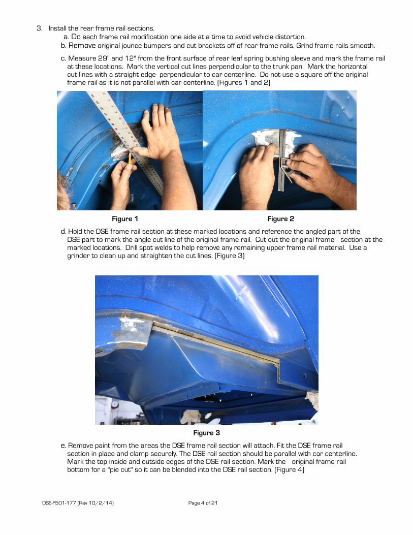
c. Measure 29" and 12" from the front surface of rear leaf spring bushing sleeve and mark the frame rail at these locations. Mark the vertical cut lines perpendicular to the trunk pan. Mark the horizontal cut lines with a straight edge perpendicular to car centerline. Do not use a square off the original frame rail as it is not parallel with car centerline. (Figures 1 and 2)
Figure 1 Figure 2
d. Hold the DSE frame rail section at these marked locations and reference the angled part of the DSE part to mark the angle cut line of the original frame rail. Cut out the original frame section at the marked locations. Drill spot welds to help remove any remaining upper frame rail material. Use a grinder to clean up and straighten the cut lines. (Figure 3)
Figure 3
e. Remove paint from the areas the DSE frame rail section will attach. Fit the DSE frame rail section in place and clamp securely. The DSE rail section should be parallel with car centerline. Mark the top inside and outside edges of the DSE rail section. Mark the original frame rail bottom for a "pie cut" so it can be blended into the DSE rail section. (Figure 4)

DSE-F501-177 (Rev 10/2/14) Page 5 of 21
Figure 4
f. Remove the DSE frame rail section to make the "pie cut" in the original rail. At this time lay out and drill plug welding holes in the trunk pan using the rail outline drawn earlier. Apply etching primer to the surfaces that will be in-accessible after the DSE rail section is installed.
g. Fit the DSE frame rail section back in place and clamp securely. Again make sure the rail section is parallel with car centerline. Align the bottom of the original frame rail that you "pie cut" to the DSE frame rail section and tack in place. After tack welding, stitch weld all remaining seams. Grind the welds smooth in preparation for doubler plates.
h. Hold the doubler plates in position and mark, cut and bend lines as necessary. After cutting and bending the doubler plates layout and drill plug welding holes. Tack weld the doubler plates in position. Finish weld and plug weld each of the doubler plates and then finish grind the welds for a smooth, finished look. (Figures 5 and 6).
Figure 5 Figure 6
i. From the inside of the trunk remove any paint around the plug welding holes. Plug weld trunk pan to the top of the DSE frame rail section and grind smooth.
j. Repeat this process for the other side.
4. Install the upper cross-member. a. Cut the floor pan sheet metal horizontally 1-1/4" from the front fuel tank mounting flange between the
DSE inner frame rail surfaces.

DSE-F501-177 (Rev 10/2/14) Page 6 of 21
b. Cut the floor pan sheet metal along the rear spot weld flange of the original rear shock cross-member between the DSE inner frame rail surfaces.
c. Trim the upper cross-member and set into position and plug weld the front and rear flanges to the original floor and trunk sheet metal.
d. Use the provided templates to cut-out the front trunk corners for exhaust clearance. Fit and weld in the provided closeout corner pieces. This is a good time to mock-up and fit the DSE fuel tank.
e. Make a flat piece out of 1/8" steel to close-out the upper cross-member to the inner frame rail face. (Figures 7-12)
Figure 7
Figure 8

DSE-F501-177 (Rev 10/2/14) Page 7 of 21
Figure 9
Figure 10

DSE-F501-177 (Rev 10/2/14) Page 8 of 21
Figure 11
Figure 12

DSE-F501-177 (Rev 10/2/14) Page 9 of 21
5. Install the upper shock mounts. a. Measure between the inner frame rail surfaces to mark center on the Anti-Roll Bar (ARB) cross-
member. b. Mark a vertical line 16-1/2" from each side of the cross-member centerline. c. Position the outboard surface of the upper shock mounts at these marks and tack in place. The side
with the welded bushing faces outboard. Finish weld and plug weld each upper shock mount to the upper cross-member. (Figure 13)
Figure 13
6. Install the tubs. a. Install the DSE deep tubs as per the DSE deep tub kit instructions
7. Install the front upper link mounts.
a. Use the provided template to mark the front upper link bolt hole locations with a center punch. b. Drill 1" hole at these locations using a hole saw. c. Slide the upper link bolt mounting crush tubes through these holes. Slide the outer closeout plate over
the crush tubes and trim to fit as necessary. d. Fit the left and right upper link mounting brackets into place. Trim as necessary to fit nicely with the
inner frame rail, floor pan, and original shock cross-member surfaces and tack in place. e. Measure the overall outer-outer frame rail width at the crush tube locations and record this number.
Subtract 34.4 from this dimension and divide by 2. This calculated number is the distance the inboard end of the crush tube should be from each outer frame rail surface. Set each crush tube to this dimension and tack in place.
f. Slide outer frame rail doubler over outboard side of crush tube and tack in place. g. Use provided 2.42" spacer to position inner closeout plate. Trim to fit as necessary and tack in place. h. Finish weld and plug weld both upper link mount assembles and remove 2.42" spacer. i. Trim the outer edge of the crush tube that extends past the outer frame rail leaving the weld. This will
allow you more clearance for the bolt head between the frame rail and the inside flange of the deep tub when installing the upper link.
j. Repeat this procedure for the other side. (Figures 14-16)

DSE-F501-177 (Rev 10/2/14) Page 10 of 21
Figure 14
Figure 15

DSE-F501-177 (Rev 10/2/14) Page 11 of 21
Figure 16
8. Install the torque boxes.
a. Refer to the instructions provided in the torque box kit.
9. Install the front lower link mounts. NOTE: This section of the instructions has been updated since the installation DVD was created.
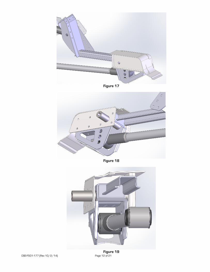
a. Slide the 1” OD x 3.0”L crush tubes into the lower link mounts. Slide the lower link mount assemblies up into each torque box and install the 1/2”-20 x 7.0”L bolts, washers and Nylock nuts and tighten. b. Make sure the top surface of the link mount seats flat on the bottom surface of the torque box. The link mounts should be approximately centered in the torque boxes and set the distance between each inner link mount surface to 29-5/16”. Tack weld each lower link mount to the 1” OD crush tube. Remove and finish weld the crush tubes into the lower link mounts. c. Re-install the lower link mount assembly into the torque boxes and torque the 1/2”-20 x 7.0”L bolts to 75 ft-lbs. Install a 2.42” long spacer in the center hole of each link mount assembly and final weld by plug welding the link mount assembly to the torque boxes and then perimeter weld. d. Cut and trim the front upper link mount braces as necessary to properly fit between the back lower link mount surfaces and the front surface of the upper link mounting bracket. (Figures 17-19). e. Remove the emergency brake cable brackets from each frame rail.
DSE-F501-177 (Rev 10/2/14) Page 12 of 21
Figure 17
Figure 18
Figure 19

DSE-F501-177 (Rev 10/2/14) Page 13 of 21
10. Install the track bar body bracket. a. Position the track bar body bracket into place and tack. b. The top edges should sit on the DSE frame rail sections and trunk corner closeout. Use the extended
lip at the top on the forward surface to set the bracket parallel with the ARB cross-member surface. With the vehicle level, the track bar bracket should be 90° (perpendicular) to the vehicle on both sides. Once correct location is verified finish weld. (Figure 20)
Figure 20
11. Install the axle brackets
a. It is recommended that the axle brackets are installed when the axle tube flanges are not on the axle. If a new axle is being installed or the existing axle is being narrowed, install the axle brackets first, and then install the flanges. If the flanges are not removed, cut the axle brackets apart and weld them back together around the axle tube.
b. It is important that the correct width for the bushings is maintained on the axle brackets when they are welded; therefore, the 2.42" spacers provided with the kit should be installed in the brackets in these areas during welding. Weld the axle bracket reinforcements on each bracket and position the axle brackets on the axle tubes. If you are cutting the axle bracket the reinforcements will be welded on after the axle bracket is in position and welded back together. Use the print in these instructions to locate the axle brackets on the rearend housing (See Figure 26). NOTE: Detroit Speed offers a pinion centering tool (P/N 070202) that will be helpful in placing your axle brackets in the correct location on your axle tube.
c. Tack weld the brackets in place, and then verify that they are all positioned correctly. Weld the brackets securely in place.
d. Install and weld the lower link/coilover reinforcement brackets as shown on Figure 26, if not done previously.
e. The track bar axle bracket mounts outboard of the RH axle bracket as shown in Figure 26. Position the track bar axle bracket in place and tack weld. Verify the bracket fits tight to the axle bracket and around the axle tube and finish weld.
f. Once all of the axle brackets are fully welded in place, remove the spacers, and check the axle for straightness.
g. Position the ARB end-link brackets so that the 90° gusset mates up against the lower link/coilover bracket side surface. Clock the bracket so the end-link hole is centered on the axle tube. Use the included print to help set location. Tack each bracket in place and verify correct location before finish welding.
DSE-F501-177 (Rev 10/2/14) Page 14 of 21
12. Verify the installation a. At this point the fabrication work is complete. Send the axle to a qualified shop to have the ends
welded (if necessary). b. Check the axle tubes for straightness and have them straightened (if needed). c. Mocking up the car before painting all of the components is recommended. Mock up includes
installing all of the suspension components (the link bolts still don’t need to be tightened yet) installing the wheels/tires, and resting the vehicle on all four tires.
d. Position the rear axle in place under the car and install the links. See the side view geometry diagram for information on link mounting positions. Nominal position for the track bar is bottom hole on the body mounting bracket. The track bar should be level at ride height.
e. Support the axle at ride height. Check the axle position in the car and adjust the end links as necessary. Nominal ride height is 15" center-center on the shock mounting holes.
f. Install the coilover shocks and springs so you can double check that the rear axle is positioned correctly in the vehicle. It should be centered from side to side, and the wheelbase should be correct on both sides of the vehicle (108.0” for a 1964.5 - 1970 Mustang). The pinion angle should be measured and adjusted to your preference. 4° down is recommended. Raise and lower the vehicle to verify that there is no interference. Now is a good time to install the exhaust system.
g. Paint or coat the components as desired.
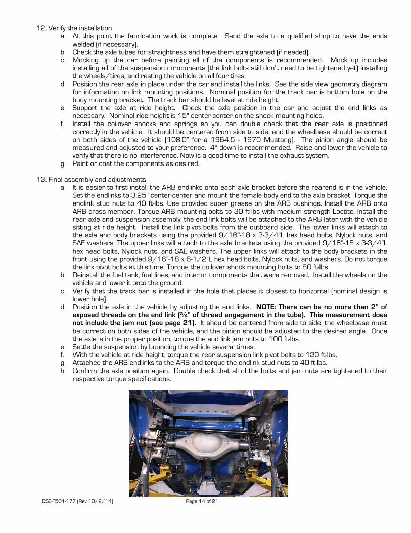
13. Final assembly and adjustments a. It is easier to first install the ARB endlinks onto each axle bracket before the rearend is in the vehicle.
Set the endlinks to 3.25" center-center and mount the female body end to the axle bracket. Torque the endlink stud nuts to 40 ft-lbs. Use provided super grease on the ARB bushings. Install the ARB onto ARB cross-member. Torque ARB mounting bolts to 30 ft-lbs with medium strength Loctite. Install the rear axle and suspension assembly; the end link bolts will be attached to the ARB later with the vehicle sitting at ride height. Install the link pivot bolts from the outboard side. The lower links will attach to the axle and body brackets using the provided 9/16”-18 x 3-3/4”L hex head bolts, Nylock nuts, and SAE washers. The upper links will attach to the axle brackets using the provided 9/16”-18 x 3-3/4”L hex head bolts, Nylock nuts, and SAE washers. The upper links will attach to the body brackets in the front using the provided 9/16”-18 x 6-1/2”L hex head bolts, Nylock nuts, and washers. Do not torque the link pivot bolts at this time. Torque the coilover shock mounting bolts to 80 ft-lbs.
b. Reinstall the fuel tank, fuel lines, and interior components that were removed. Install the wheels on the vehicle and lower it onto the ground.
c. Verify that the track bar is installed in the hole that places it closest to horizontal (nominal design is lower hole].
d. Position the axle in the vehicle by adjusting the end links. NOTE: There can be no more than 2” of exposed threads on the end link (¾” of thread engagement in the tube). This measurement does not include the jam nut (see page 21). It should be centered from side to side, the wheelbase must be correct on both sides of the vehicle, and the pinion should be adjusted to the desired angle. Once the axle is in the proper position, torque the end link jam nuts to 100 ft-lbs.
e. Settle the suspension by bouncing the vehicle several times. f. With the vehicle at ride height, torque the rear suspension link pivot bolts to 120 ft-lbs. g. Attached the ARB endlinks to the ARB and torque the endlink stud nuts to 40 ft-lbs. h. Confirm the axle position again. Double check that all of the bolts and jam nuts are tightened to their
respective torque specifications.

DSE-F501-177 (Rev 10/2/14) Page 15 of 21
Lower Link Adjustment Settings
Axle Bracket Position Body Bracket Position Instant Center Notes Bottom Hole Top Hole 40.5" / 9.8" Frame must be modified Bottom Hole Middle Hole 48.5" / 8.6" DSE Nominal Setting Bottom Hole Bottom Hole 60.4" / 6.8"
Middle Hole Top Hole 44.5" / 9.2" Middle Hole Middle Hole 55.8" / 7.5" Middle Hole Bottom Hole 75.0" / 4.6"
Top Hole Top Hole 108.3" / -0.3" Top Hole Middle Hole 69.4" / 5.5" Top Hole Bottom Hole 51.0" / 8.2"
Instant center numbers are expressed as distance forward of rear axle centerline, then height above ground level.
Nominal Position Shown Instant Center: 48.5" Forward of Rear Axle Centerline 8.6" Above Ground Level
**See chart below for adjustment info**

DSE-F501-177 (Rev 10/2/14) Page 16 of 21
14. Setting the vehicle ride height. a. With the vehicle assembled with all components installed, adjust the ride height as necessary. Detroit Speed does recommend using a small wipe of anti-seize before adjusting the spanner nut and compressing the coilover spring. b. Detroit Speed does include a Spanner Tool (P/N: 031060) to adjust ride height however if you have the adjustable coilover shocks, Detroit Speed does offer an Adjustment Tool available as P/N: 031061 if needed. A photo can be seen in Figure 21.
Figure 21 – DSE Spanner & Adjustment tools
15. If the Single Adjustable, Double Adjustable or the Double Adjustable Remote Canister Coilovers were
purchased as an upgrade, refer to the following information for adjustment procedures.
PLEASE NOTE: ALL ADJUSTABLE TYPE SHOCKS GET MOUNTED BODY SIDE UP SHAFT SIDE DOWN DSE Single Adjustable Shock Applications To change from the recommended “Detroit Tuned” valving, adjustments can be made independently to the rebound setting. The rebound is controlled by the knob at the lower shock mount (Shock is mounted body side up). The knob rotates clockwise (+) to increase the damping and counterclockwise (-) to decrease the damping. Refer to Figure 22a below
Figure 22a- DSE Single Adjustable Shock
To return to the DSE recommended settings, turn the knob clockwise (+) to full damping. Once at full damping, turn counterclockwise (-) to reach the recommended settings. Refer to Figure 22b for the recommended starting setting.
Rebound (Shaft Knob)……… 20 Open (counterclockwise, -)
Figure 22b – DSE Recommended Settings
Rebound Knobs

DSE-F501-177 (Rev 10/2/14) Page 17 of 21
Adjuster Operation
Adjuster (60-64 Clicks) The low-speed adjuster is a “clicker” style adjuster meaning that its adjustment is measured by detents located inside the blue adjuster knob. There are 16 clicks per 1 revolution of the knob. It uses a right-hand thread in its operation which means as you increase low-speed, the adjuster will move up on the eyelet. The recommended change for an adjustment is 8 clicks at a time. The low-speed adjuster’s reference position is full stiff (closed, or all the way up) and referred to -0 (-0 = full stiff, -64 = full soft).
Tuning Notes o Racetrack
For more grip, soften the damping.
For increased platform control, stiffen the damping. o Street
For a more comfortable ride, soften the damping
*DO NOT FORCE KNOB WHEN IT STOPS TURNING, YOU MAY DAMAGE THE ADJUSTER AND INTERNAL HARDWARE
DSE Double Adjustable Shock Applications
To change from the recommended “Detroit Tuned” valving, adjustments can be made independently to both the high and low speed settings. The rebound is controlled by the sweepers at the lower shock mount. The sweepers rotate clockwise (+) to increase the damping and counterclockwise (-) to decrease the damping. The sweepers can be seen in Figure 23a.
Low-Speed Adjuster CLOSE
+ (Stiffer)
- (Softer)

DSE-F501-177 (Rev 10/2/14) Page 18 of 21
Figure 23a – DSE Double Adjustable Shock
When adjusting the low speed rebound start at full (+) position, when adjusting the high speed rebound start at full (-) position. To return to the DSE recommended settings turn the sweeper clockwise(+) to full damping for the low speed setting, and counterclockwise (-) to full damping for the high speed setting. Once at full damping, turn counterclockwise(-) for the low speed setting, and clockwise(+) for the high speed setting to reach the recommended settings. Refer to Figure 23b for recommended starting settings.
Low Speed Rebound (Sweeper)………High Speed Rebound (Sweeper)………
20 sweeps (counterclockwise)(-) 2 sweeps(clockwise)(+)
Figure 23b – DSE Recommended Settings
DSE Double Adjustable Shocks w/Remote Canisters
To change from the recommended “Detroit Tuned” valving, adjustments can be made independently to both the high and low speed settings. The rebound is controlled by the sweepers at the lower shock mount. The sweepers rotate clockwise (+) to increase the damping and counterclockwise (-) to decrease the damping. Refer to Figure 24a.
Figure 24a – DSE Double Adjustable Shock w/ Remote Canister
When adjusting the low speed rebound start at full (+) position, when adjusting the high speed rebound start at full (-) position. To return to the DSE recommended settings turn the sweeper clockwise(+) to full damping for the low speed setting, and counterclockwise (-) to full damping for the high speed setting. Once at full damping, turn counterclockwise (-) for the low speed setting, and clockwise(+) for the high speed setting to reach the recommended settings. Refer to Figure 24b for recommended starting settings.
Low Speed Rebound (Sweeper)………High Speed Rebound (Sweeper)………
20 sweeps (counterclockwise)(-) 2 sweeps(clockwise)(+)
Figure 24b – DSE Recommended Settings
Sweepers
Sweepers
Charge Valve

DSE-F501-177 (Rev 10/2/14) Page 19 of 21
Adjuster Operation
High-Speed Adjuster (12 Sweeps)
The high-speed adjuster is a “sweep” style adjuster meaning that its adjustment is measured by the location of the adjuster in the eyelet window. It uses a left-hand thread in its operation which means; as you increase high-speed, the adjuster will move down in the window*. The high-speed adjuster’s reference position is full soft and referred to as +0 (+0 = full soft, +12 = full stiff).
Low-Speed Adjuster (25 Clicks)
The low-speed adjuster is a “clicker” style adjuster meaning that its adjustment is measured by detent grooves located inside the high-speed shaft. It uses a right-hand thread in its operation which means; as you increase low-speed, the adjuster will move up in the window. The low-speed adjuster’s reference position is full stiff and referred to -0 (-0 = full stiff, -25 = full soft).
*The low-speed adjustment does not change when adjusting the high-speed. To aid in the installation of the reservoirs, we also offer a set of Billet Aluminum Remote Canister Mounts. The canister mounts are available exclusively through DSE, P/N: 032102. They are shown below in Figure 27.
Figure 25 - Billet Aluminum Remote Canister Mounts
Legal Disclaimer: Detroit Speed, Inc. is not liable for personal, property, legal, or financial damages from the use or misuse of any product we sell. The purchaser is solely responsible for the safety and performance of these products. No warranty is expressed or implied.
High-Speed Adjuster REBOUND
Low-Speed Adjuster
OPEN
+ (Stiffer)
- (Softer)

DSE-F501-177 (Rev 10/2/14) Page 20 of 21
Once again, we appreciate your business.
If you have any questions during the installation of this product, call (704) 662-3272.
Figure 26

DSE-F501-177 (Rev 10/2/14) Page 21 of 21
Detroit Speed, Inc. Swivel-Links
WARNING:
There can be no more than 2” of exposed threads on the end link (3/4” of thread engagement in the tube). This measurement does not include the jam nut (see below).