Embed Size (px)
Citation preview
DSE-F501-221 (Rev 06/09/15) Page 1 of 27
Detroit Speed, Inc. 1964.5 - 1970 Mustang Mini-Tub Kit
P/N: 041231
Figure 1 - Not All Hardware Shown
Item Component Quantity
1 DSE Mini-Tubs – 1964.5-70 Mustang 2
2 Frame Rail Sections 2
3 Doubler Plate 4" x 3.25" 4
4 Doubler Plate 4" x 2" 4
5 1” OD x 2.25”L Torque Box Crush/Tube Spacer 2
6 Torque Box OB Plate 2
7 Torque Box IB Plate – LH and RH 2

DSE-F501-221 (Rev 06/09/15) Page 2 of 27
8 Torque Box Bottom Plate – LH and RH 2
9 Torque Box Top Assembly – LH and RH 2
10 Torque Box Weld Spacer (with Groove) 1
11 Upper Shock Mount Assembly – LH and RH 2
12 Mini-Tub Kit Rear Support Tube 1 13 Shackle Mount Assembly 2 14 Shackle 4
15 Shackle Crush Tube 4
16 Leaf Spring Shackle Urethane Bushing 8
17 Support Tube Frame Locator 4
18 Support Tube Frame Locator Lower Bracket 4
19 Mini-Tub Kit Trunk Closeout – LH and RH 2
20 Adjustable Leaf Spring Pad 2
21 1/2”-20 U-Bolt Kit 1
22 Lower Shock Plate – LH and RH 2
23 DSE Rear Leaf Spring (1-1/2” Drop) 2
24 Mini-Tub Shock 2
25 Template 1 26 Instructions 1
Hardware Checklist – Mustang Mini-Tub Kit
Part Number Description Quantity Check
9304188 Support Tube/Shackle Hardware Kit 1
950083FS 5/16”-24 x 1-1/4”L Hex Head Bolt Grade 8 8
980041FS 5/16”-24 x 1”L Hex Head Bolt Grade 8 8
960049FS 5/16” Grade 8 Nylock Nut 16
970041FS 5/16” SAE Flat Washer 32
980039FS 1/2”-20 x 4-1/2”L Hex Head Bolt Grade 8 4
980043FS 1/2”-20 x 4”L Hex Head Bolt Grade 8 2
960004FS 1/2”-20 Grade 8 Nylock Nut 6
970037FS 1/2” SAE Flat Washer 12
9304189 Mustang Torque Box Hardware Kit 1
980077FS 1/2”-20 x 7”L Hex Head Bolt Grade 8 2
960004FS 1/2”-20 Grade 8 Nylock Nut 2
970037FS 1/2” SAE Flat Washer 4
9304190 Mustang Mini-Tub Shock Hardware Kit 1
99030189 Polyurethane Anti-Roll Bar End Link Grommets, Black 4
99030190 Anti-Roll Bar End Link Stamped Washers 4 960083FS M10 x 1.5 Hex Nut 4
980058FS 1/2”-20 x 3”L Hex Head Bolt Grade 8 2
960004FS 1/2”-20 Grade 8 Nylock Nut 2
970037FS 1/2” SAE Flat Washer 2
99030169F 3/4” OD x 1/2” ID x 1/4”L Spacer 2

DSE-F501-221 (Rev 06/09/15) Page 3 of 27
INTRODUCTION Congratulations on your purchase of the DSE Mustang Rear Mini-Tub Kit. Please read the entire set of instructions and fully understand all of the steps involved before beginning the project.
NOTES: 1. All work should be performed by a qualified welder and technician. 2. There is an installation video available through the DSE website shown here:
http://www.detroitspeed.com/tech/installation-videos.html.
3. The factory fuel tank will not work with the DSE Mini-Tub Kit. DSE does offer a Mini-Tub Kit fuel tank for a carbureted or fuel injected engine with multiple fuel pump options for the 1964.5-1970 Mustang application (P/N 080124).
4. The rear axle used with this kit requires 3” O.D. axle tubes. 5. The rear valence on a 1965-66 Mustang GT will not work with the DSE Mini-Tub Kit.
PREPARING THE VEHICLE 1. Raise the vehicle a few feet off of the ground so the interior, trunk, and the underside of the
vehicle are accessible. Ensure the vehicle is level and well supported. 2. Disconnect the battery cables.
3. Remove the gas tank and fuel lines. NOTE: Make sure to eliminate all of the fuel vapors from the
work area before continuing. 4. Remove the rear suspension and axle. 5. Remove the seats, carpet, carpet padding, rear interior quarter trim panels, and package tray.
Any other interior panels, headliner, door panels, etc., should be removed or masked well to protect them from grinding and welding sparks.
6. Remove the trunk lid, springs, and hinges. Take care when removing the trunk springs as they are under high tension when installed.
INSTALLING THE DSE FRAME RAIL SECTIONS 1. Each frame rail modification should be done one side at a time to avoid vehicle distortion. 2. Remove the original jounce bumpers and cut the brackets off of the rear frame rails. Grind the
frame rails smooth. 3. Measure 29" and 12" from the front surface of the rear leaf spring bushing sleeve and mark the
frame rail at these locations. Mark the vertical cut lines perpendicular to the trunk pan. Mark the horizontal cut lines with a straight edge perpendicular to the car centerline. Do not use a square of the original frame rail as it is not parallel with the car centerline. (Figures 1 and 2 on the next page)

DSE-F501-221 (Rev 06/09/15) Page 4 of 27
Figure 1 Figure 2
4. Hold the DSE frame rail section at these marked locations and reference the angled part of the DSE part to mark the angle cut line of the original frame rail. Cut the original frame section at the marked locations. Drill spot welds to help remove any remaining upper frame rail material. Use a grinder to clean and straighten the cut lines. (Figure 3)
Figure 3
5. Remove the paint from the areas where the DSE frame rail section will attach. Fit the DSE frame rail section in place and clamp securely. The DSE rail section should be parallel with the car centerline. Mark out the top inside and outside edges of the DSE rail section. Mark the original frame rail bottom for a "pie cut" so it can be blended into the DSE rail section. (Figure 4)
Figure 4

DSE-F501-221 (Rev 06/09/15) Page 5 of 27
6. Remove the DSE frame rail section to make the "pie cut" in the original rail. At this time lay out and drill plug welding holes in the trunk pan using the rail outline drawn earlier. Apply etching primer to the surfaces that will be in-accessible after the DSE rail section is installed.
7. Fit the DSE frame rail section back in place and clamp securely. Again make sure the rail section is parallel with the car centerline. Align the bottom of the original frame rail that you "pie cut" to the DSE frame rail section and tack in place. After tack welding, stitch weld all remaining seams. Grind the welds smooth in preparation for doubler plates.
8. Hold the doubler plates in position and mark, cut and bend lines as necessary. After cutting and
bending the doubler plates layout and drill plug welding holes. Tack weld the doubler plates in position. Finish weld and plug weld each of the doubler plates and then finish grind the welds for a smooth, finished look. (Figures 5 and 6)
Figure 5 Figure 6
9. From the inside of the trunk remove any paint around the plug welding holes. Plug weld the trunk
pan to the top of the DSE frame rail section and grind smooth. 10. Repeat this process for the other side.
INSTALLING THE DSE MINI-TUBS (NOTE: The Mini-Tubs should be installed at the 2" standard depth in most cases. The extra 3" depth is primarily meant for 65-66 models to get a 315 tire. The 3" install will require cutting into and narrowing the DSE frame sections installed in the previous section. See the tire fitment chart in Figure 27). 1. Locate and document the position of any brackets that need to be removed to install the mini-
tubs. Remove these brackets and save for re-use. Fastback application shown on the next page. (Figures 1-4)

DSE-F501-221 (Rev 06/09/15) Page 6 of 27
Figure 1 Figure 2
Figure 3 Figure 4
2. For the coupe application: drill spot welds out of the upper decklid hinge mounting flange and
separate. Cut the lower deck lid hinge bracket out of the stock tub and remove the hinge assembly from the car. Remove the rear seat corner support completely from the car. First drill out the spot welds in the upper areas of the bracket and separate from the body structure. Cut the remaining section out of the stock tub and remove the bracket from the car. After the bracket is removed from the car, grind spot welds and remove the stock tub material from the flanged area. Straighten and grind the part smooth for re-use later. (Figures 5 and 6 on the next page)
Figure 5
Drill out spot welds.
Cut tub out around lower hinge
to remove.

DSE-F501-221 (Rev 06/09/15) Page 7 of 27
Figure 6
For the fastback application: cut rear seat side structure away to clear the DSE mini-tub. A pair of dividers can be used to layout your bend line. Set the dividers to 2" or 3" to match the depth of your mini-tub install. Create an arc on the seat bracket keeping the dividers parallel with the floor (Figures 7 and 8). Center punch and drill out the spot welds of the upper support and detach from the tub flange (Figure 9 on the next page). Cut the stock tub around the inside of the support flange. Remove the support flange section for later use.
Figure 7
Figure 8

DSE-F501-221 (Rev 06/09/15) Page 8 of 27
Figure 9
3. Cut the supplied mini-tub floor pan cut template to the appropriate depth for your mini-tub install.
If you are doing a 3" mini-tub install you will be cutting into the DSE frame rail sections installed earlier. Lay the template up against the original tub and then mark out your floor pan cut line. At this point begin removing the original tub by cutting vertically along the edge of the inner stepped surface, which is about 1" inboard of the inner-outer tub seam. Cut and remove the original lower front tub flange. Cut the remaining edge along the flange by the frame rail to allow removal of the main tub section. You now have better access, and can proceed with cutting the floor pan cut line made earlier with the template. After removing the floor pan section trim away any remaining small pieces. (Figures 10 below, 11 and 12 on the next page)
Figure 10

DSE-F501-221 (Rev 06/09/15) Page 9 of 27
Figure 11
Figure 12
4. For a standard 2" mini-tub install, mark a cut line 1" from the tub edge on the new mini-tub. Trim the tub on this line and debur. (For a 3" mini-tub install no trimming of the mini-tub is required.) (Figure 13)
Figure 13

DSE-F501-221 (Rev 06/09/15) Page 10 of 27
5. Fit the mini-tub up into the car to check general fitment and gaps. Mark any gaps or tight spots accordingly and adjust. Re-fit the mini-tub until all areas of fitment look acceptable.
6. Use a piece of poster board to trace the outline of the floor pan to make a template for your
mini-tub flange. Mark 1" increments along the curve of your line to finalize the template. Cut the template out and trace onto a section of 16-18ga steel. Cut the flange out and bend to fit the floor pan. When the flange fitment is good, remove paint around where the flange will be welded. Spray etching primer to necessary surfaces that will be in-accessible later. Clamp flange in position and tack weld in place. Stitch weld the entire flange and grind smooth. (Figures 14 and 15)
Figure 14
Figure 15
DSE-F501-221 (Rev 06/09/15) Page 11 of 27
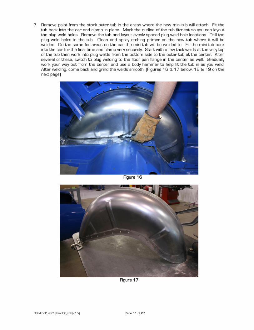
7. Remove paint from the stock outer tub in the areas where the new mini-tub will attach. Fit the tub back into the car and clamp in place. Mark the outline of the tub fitment so you can layout the plug weld holes. Remove the tub and layout evenly spaced plug weld hole locations. Drill the plug weld holes in the tub. Clean and spray etching primer on the new tub where it will be welded. Do the same for areas on the car the mini-tub will be welded to. Fit the mini-tub back into the car for the final time and clamp very securely. Start with a few tack welds at the very top of the tub then work into plug welds from the bottom side to the outer tub at the center. After several of these, switch to plug welding to the floor pan flange in the center as well. Gradually work your way out from the center and use a body hammer to help fit the tub in as you weld. After welding, come back and grind the welds smooth. (Figures 16 & 17 below, 18 & 19 on the next page)
Figure 16
Figure 17

DSE-F501-221 (Rev 06/09/15) Page 12 of 27
Figure 18
Figure 19
8. Make a poster board template to re-create the small flap that was removed with the stock tub. Cut the part out of 16-18ga steel, spray with etching primer, and tack weld into position. Stitch weld, plug weld, and grind smooth to complete the small flap install. (Figures 20 and 21 on the next page)

DSE-F501-221 (Rev 06/09/15) Page 13 of 27
Figure 20
Figure 21
9. Return to the inside of the car and stitch weld the mini-tub to the floor pan. At least 8 stitch welds
or more are recommended. (Figure 22)
Figure 22

DSE-F501-221 (Rev 06/09/15) Page 14 of 27
10. For the coupe application: modify and fit the lower section of the deck lid hinge bracket to the DSE mini-tub. Weld the upper part of the hinge mount back to the original flange piece still on the car. Stitch weld and plug weld the lower section into position. Fit the rear seat corner support that was removed earlier to the DSE mini-tub. A small extension piece will probably have to be added to the top outboard edge since the bracket will be shifted inboard by the mini-tub. Drill holes for plug welding in the applicable areas and tack weld the bracket into position. Weld any other remaining brackets back into position that were removed from the stock tubs. (Figures 23 and 24)
Figure 23
Figure 24
Modify lower hinge bracket to fit
new mini-tub.
Added extension to seat bracket.

DSE-F501-221 (Rev 06/09/15) Page 15 of 27
For the fastback application: modify, fit and weld in the rear seat corner support that connects the DSE deep tub to the original rear seat structure. Modify, fit, and weld the upper support flange piece to the top of the deep tub. A flange will have to be added to the bend line marked out during removal. Weld any other remaining brackets that were removed from the stock tubs. (Figures 25 & 26)
Figure 25
Figure 26

DSE-F501-221 (Rev 06/09/15) Page 16 of 27
Figure 27
TORQUE BOX INSTALLATION
NOTE: This section has been updated since the original DVD was made.
1. Begin by properly supporting the vehicle under the rear axle and front frame to avoid tension in
the body when installing Torque Box Kit. 2. (64.5 – 66 years only) Locate the two spot welds in the bottom of the frame rail for the factory
leaf spring bolt crush tube. Drill out one spot weld and use a screwdriver or pry bar to pry the factory crush tube out of the way. (Can be accessed through the hole in the frame rail). Drill the inboard leaf spring bolt hole in the frame rail to 1-1/16”. (Figures 1 & 2)
Figure 1 Figure 2

DSE-F501-221 (Rev 06/09/15) Page 17 of 27
3. Install the new 2.25” long crush tube through the frame rail from the inboard side. Slide the outer torque box plate over the crush tube and clamp the plate to the inboard side of the frame rail. Install a 1/2”-20 x 7.0”L bolt with the provided weld spacer with the groove through the new crush tube and the factory leaf spring mount and tighten. (This will set the crush tube to proper alignment position).
4. Fit the upper plate to the contour of the car’s floor pan. Once desired fitment is set, hold the
upper plate in position and trace its outline on the floor pan surface. This gives you the area to clean up for welding and where to drill a pattern of plug welding holes. Once the area is cleaned up and drilled for plug welding it can be fully welded into place. (Figure 3 & 4)
Figure 3 Figure 4
5. Use the provided weld spacer tube with the groove to bolt the inner torque box plate into place.
(It may be necessary to grind on the front edge of the plate to fit the profile of your specific floor pan). Tack weld the plate in place.
6. The bottom torque box plate can now be fitted into position between the inner and outer plates.
The bottom surface should be set so it is .785” below center of the leaf spring bolt hole. Tack weld into place. (Figure 5)
Figure 5

DSE-F501-221 (Rev 06/09/15) Page 18 of 27
7. Leave the weld spacer in place and finish weld all areas at this time. Remove the weld spacer once everything has cooled to room temperature (Figure 6)
8. Repeat the above process for the other side of the vehicle.
Figure 6
INSTALLING THE REAR TRUNK CLOSEOUTS 1. With the fuel tank removed, grind any paint, etc. at the back corner of the trunk pan so you have
a smooth surface to install the rear support tube and trunk closeouts.
2. Set the mini-tub closeouts in position in the trunk pan. With the closeouts square to the vehicle, trace the side that overlaps the trunk pan. (Figure 1 & 2).
Figure 1 Figure 2
3. Using a set of dividers, set them to 3/4” to leave a flange on the trunk pan to weld the closeouts. (Figure 3 on the next page). Cut this section of the trunk floor and check fitment with both closeouts. As a reference dimension, the distance between the inside of the trunk closeouts should be about 26-1/2” across depending on vehicle variation.
DSE-F501-221 (Rev 06/09/15) Page 19 of 27
Figure 3
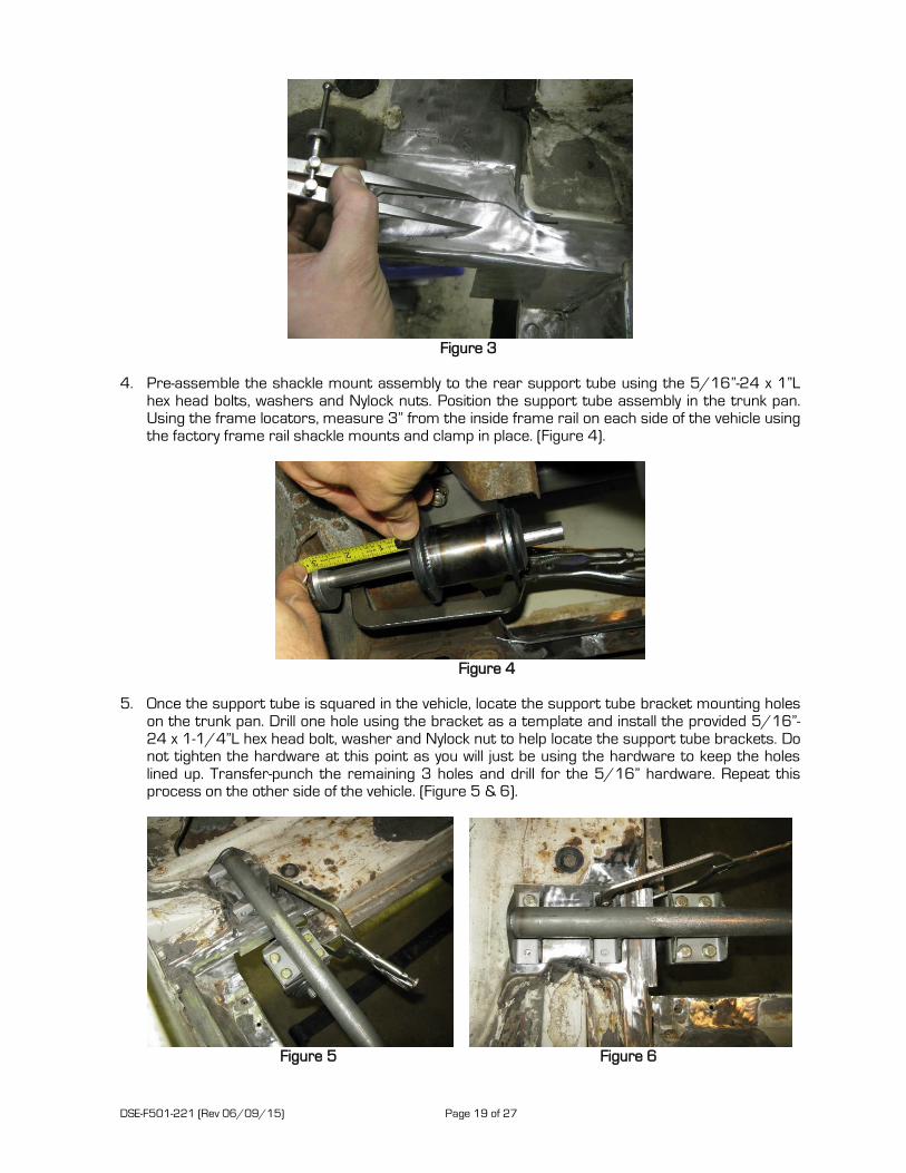
4. Pre-assemble the shackle mount assembly to the rear support tube using the 5/16”-24 x 1”L
hex head bolts, washers and Nylock nuts. Position the support tube assembly in the trunk pan. Using the frame locators, measure 3” from the inside frame rail on each side of the vehicle using the factory frame rail shackle mounts and clamp in place. (Figure 4).
Figure 4
5. Once the support tube is squared in the vehicle, locate the support tube bracket mounting holes
on the trunk pan. Drill one hole using the bracket as a template and install the provided 5/16”-24 x 1-1/4”L hex head bolt, washer and Nylock nut to help locate the support tube brackets. Do not tighten the hardware at this point as you will just be using the hardware to keep the holes lined up. Transfer-punch the remaining 3 holes and drill for the 5/16” hardware. Repeat this process on the other side of the vehicle. (Figure 5 & 6).
Figure 5 Figure 6

DSE-F501-221 (Rev 06/09/15) Page 20 of 27
6. Remove the support tube from the vehicle in order to install the closeouts. Drill plug weld holes in the closeouts and plug weld to the trunk pan. (Figure 7).
Figure 7
7. Once the closeouts are welded, re-install the support tube in order to locate the shackle mount brackets onto the closeouts. Using the support tube brackets as a template you can locate and drill the 8 holes through the closeouts. Using the provided 5/16” x 1”L hex head bolts, washers and Nylock nuts to make sure all bolts will line up through the support tube brackets and both closeouts. (Figure 8).
Figure 8
DSE-F501-221 (Rev 06/09/15) Page 21 of 27
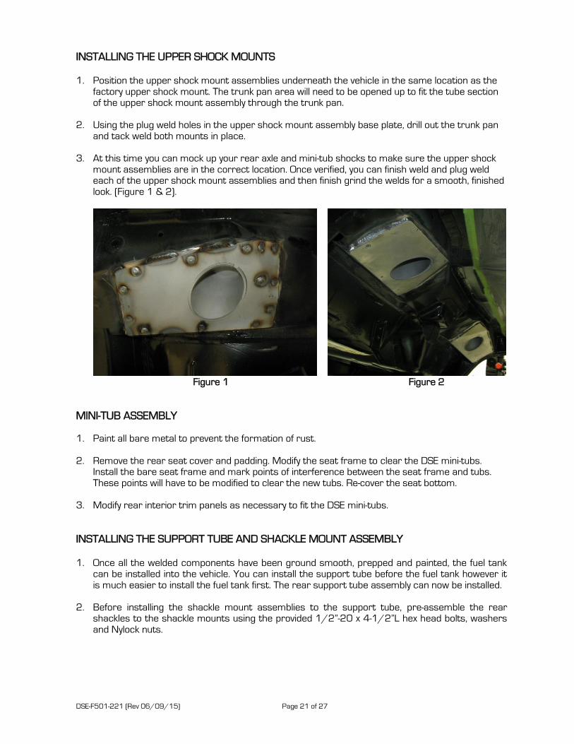
INSTALLING THE UPPER SHOCK MOUNTS 1. Position the upper shock mount assemblies underneath the vehicle in the same location as the
factory upper shock mount. The trunk pan area will need to be opened up to fit the tube section of the upper shock mount assembly through the trunk pan.
2. Using the plug weld holes in the upper shock mount assembly base plate, drill out the trunk pan
and tack weld both mounts in place.
3. At this time you can mock up your rear axle and mini-tub shocks to make sure the upper shock mount assemblies are in the correct location. Once verified, you can finish weld and plug weld each of the upper shock mount assemblies and then finish grind the welds for a smooth, finished look. (Figure 1 & 2).
Figure 1 Figure 2
MINI-TUB ASSEMBLY 1. Paint all bare metal to prevent the formation of rust. 2. Remove the rear seat cover and padding. Modify the seat frame to clear the DSE mini-tubs.
Install the bare seat frame and mark points of interference between the seat frame and tubs. These points will have to be modified to clear the new tubs. Re-cover the seat bottom.
3. Modify rear interior trim panels as necessary to fit the DSE mini-tubs.
INSTALLING THE SUPPORT TUBE AND SHACKLE MOUNT ASSEMBLY 1. Once all the welded components have been ground smooth, prepped and painted, the fuel tank
can be installed into the vehicle. You can install the support tube before the fuel tank however it is much easier to install the fuel tank first. The rear support tube assembly can now be installed.
2. Before installing the shackle mount assemblies to the support tube, pre-assemble the rear
shackles to the shackle mounts using the provided 1/2”-20 x 4-1/2”L hex head bolts, washers and Nylock nuts.

DSE-F501-221 (Rev 06/09/15) Page 22 of 27
3. Install the 5/16”-24 x 1”L hex head bolts that were used in the previous step through the support tube and trunk closeouts. Install the shackle mount assemblies to the closeouts using the 5/16” washers and Nylock nuts and torque to 25 ft-lbs. Install the shackle mounts so that the head of the 1/2” bolts are closest to the fuel tank and the Nylock nuts are towards the outside of the vehicle. (Figure 1)
Figure 1
4. Position the frame locator lower brackets on both sides of the vehicle so they sit against the
factory shackle tube. Install the support tube frame locators into the lower brackets and install the provided 1/2”-20 x 4”L hex head bolts, washers and Nylock nuts. Install the bolts so that the Nylock nuts are on the inside of the frame rail and the head of the hex bolt is towards the outside of the car. (Figure 2)
Figure 2

DSE-F501-221 (Rev 06/09/15) Page 23 of 27
5. Install the provided 5/16”-24 x 1-1/4”L hex head bolts, washers and Nylock nuts through the trunk pan and the frame locator brackets that were used in the previous steps and torque to 25 ft-lbs. (Figure 3 & 4)
Figure 3 Figure 4
INSTALLING THE URETHANE REAR BUSHINGS 1. Before installing the new bushings and crush sleeves into the rear leaf spring eye, lightly coat the
following areas and parts with the grease supplied:
I.D. of the rear spring eye I.D. of the shackle bushing brackets I.D., O.D. and flange of the polyurethane bushing O.D. of the crush sleeves
2. Install the urethane bushings by first gently tapping in the bushings and then tapping in the crush sleeves.
INSTALLING THE ADJUSATBLE LEAF SPRING PADS 1. It is recommended that the spring pads be clamped securely in position once the pinion angle
and spring widths are set by mocking up the leaf springs in the vehicle. DSE recommends the pinion angle to be set at -3° to -4° down towards the ground.
2. Remove the leaf springs and permanently attach the pads by welding the lower spring pad bases
to the axle tubes. Use care when welding, excessive heat can distort the axle tubes. (Figure 1 on the next page)

DSE-F501-221 (Rev 06/09/15) Page 24 of 27
Figure 1 – Adjustable Leaf Spring Pads
INSTALLNG THE LEAF SPRINGS AND LOWER SHOCK PLATES 1. Install the leaf springs into the vehicle using the front torque box leaf spring perch and the rear
shackles. Do not torque at this time. 2. Install the rear leaf springs to the shackles with the provided 1/2”-20 x 4-1/2”L hex head bolts,
washers and Nylock nuts to mount the leaf springs to the shackle mounts. Install the leaf spring bolts from the outside so that your Nylock nuts will be on the inside closest to the fuel tank. (Figure 1)
Figure 1
3. Install the lower shock plates to the vehicle using the provided 1/2”-20 U-Bolts. (Figure 2 on the
next page). The detailed view is showing the lower shock plate from the front of the vehicle. In this kit you will have a left and a right hand shock plate as both shocks are located on the front side of the rear axle. (Figure 3 on the next page)

DSE-F501-221 (Rev 06/09/15) Page 25 of 27
Figure 2
Figure 3
INSTALLING THE MINI-TUB SHOCKS
1. Slide one shock washer and bushing over the top of the shock in that order and install the min-tub shock with the body side down through the upper shocks mounts. (Figure 1 on the next page)

DSE-F501-221 (Rev 06/09/15) Page 26 of 27
Figure 1
2. Install another shock bushing and washer in that order over the stud and fasten the two M10 x
1.5 hex nuts and tighten. Repeat this procedure on the other side of the vehicle to install the other mini-tub shock.
3. Attach the shocks to the lower shock plates using the provided 1/2”-20 x 3”L hex head bolts.
Install the bolt with the 1/4” thick spacer though the lower shock eyelet. Install the bolt though the lower shock plate and tighten with the 1/2” washer and Nylock nut. The bolt will be pointing towards the rear of the vehicle with the head of the bolt at the front of the vehicle. Repeat this procedure on the other side of the vehicle to attach the mini-tub shock to the lower shock plate. Torque the lower shock 1/2” bolts to 90 ft-lbs. (Figure 2)
Figure 2
4. With the weight of the vehicle on the rear axle, a reference length of the rear shocks at ride
height should be around 13” from eyelet to the stud mount with the DSE mini-tub shocks.

DSE-F501-221 (Rev 06/09/15) Page 27 of 27
FINAL ASSEMBLY 1. Install the DSE Mini-Tub Fuel Tank. Refer to the instructions that are included with the DSE fuel
tank for installation. 2. Reinstall the package tray, rear interior quarter trim panels, carpet padding, carpet, seats, and
any additional interior panels that were removed for the installation process. 3. With the wheels/tires installed and resting the vehicle on all four tires, check that the rear axle
is positioned correctly in the vehicle. It should be centered from side to side, and the wheelbase should be correct on both sides of the vehicle at 108.0”
4. Once the rear suspension is loaded with the weight of the vehicle, torque the front leaf spring eye
bolts and rear shackle bolts to 90 ft-lbs. 5. Check all rear clearances before driving the vehicle and make sure all hardware is tightened and
has been installed with the correct torque settings.
If you have any questions before or during the installation of this product please contact Detroit Speed at [email protected] or 704.662.3272
Legal Disclaimer: Detroit Speed and Engineering, Inc. is not liable for personal, property, legal, or financial damages from the use or misuse of any product we sell. The purchaser is solely responsible for the safety and performance of these products. No warranty is expressed or implied.