Embed Size (px)
Citation preview
Measurement Automation Monitoring, Jun. 2015, vol. 61, no. 06 275 Anna SZAJEWSKA 1, Radosław ŚWIDER 2, Janusz RYBIŃSKI 1 1 THE MAIN SCHOOL OF FIRE SERVICE, 01-629 Warszawa, Słowackiego 52/54 St. 2 THE MUNICIPAL HEADQUARTERS OF THE STATE FIRE SERVICE IN KRAKOW, 31-033 Krakow, Westerplatte 19 St.
Determining of a passenger car fire temperature
Abstract A fire test was carried out. In the test a lift back passenger car with LPG system was burnt. Fire footprints, visible only in IR were observed with a thermal camera. Temperature was measured at specific points of the car and results were presented in graphs. Comparative measurements of surface temperature were taken by a thermocouple and thermal camera. Value of emissivity coefficient was delimited using ThermaCAM Researcher programme, by Flir Co. Keywords: emissivity, thermal camera, thermogram, fireman, fire environment, firefighting. 1. Introduction
In 2014, in Poland , 8105 means of transport fires were reported. This number represented 4,8% of all fires at that period of time in Poland. It includes 6796 fires of passenger cars, with 59 caused by arson. This clearly implies economic and social importance of means of transport fires. The Main School of Fire Service carries out researches on means of transport fires [7, 8, 9]. This type of testing is also carried out in other research centers [2, 3, 4, 5, 6]. They aim at expanding and popularization the knowledge on car fires, especially passenger car fires. Field fire tests are carried out to determine basic fire parameters: temperature at specific points of the car, time before flashing, time of transition the flames from the engine to the passenger compartment, time of different fire phases. The researchers are carried out for different locations and fire initiations. Weather conditions, such as speed and direction of the wind, air temperature and cloudiness conditions are recorded during the tests. Fire parameters measured in specific conditions increase data bases used for modelling fire developments.
Thermal camera seems to be a perfect device for measuring the fire temperature [1, 10]. Measurements can be carried out from a distance, ensuring safety for the user. Working on the data is convenient as all the results are saved as digital data. The main factor impeding the implementation of a reliable measurement is lack of information on the emissivity coefficient of the car body. The reference data on this subject are very modest. Serius changes in car body surface occur during the fire. The surface is covered by soot, varnish swells, peels off and falls. All these changes influence the emissivity of car body. 2. The measurement stand
The fire test was carried out on the field of the Fire Service College of the State Fire Service in Krakow, in the place prepared for firefighters practical training. The experiment was secured by firefighters unit with a fire engine. For safety reasons, the measurement stand was located in significant distance from the burning car (Fig. 1).
The experiment used a lift back passenger car, driven by petrol and additionally equipped with LPG system. The passenger compartment is separated only figuratively from the luggage compartment in this type of cars. In technical terms both compartments are one space. This is important for the fire behavior.
The car was technically efficient, completely equipped with the drive system and accessories. The passenger compartment was fully equipped as well (the dashboard, the vehicle control system components, seats). Fire extinguisher and spare wheel were located in the boot.
Fig. 1. The measurement stand
3. Determining the emissivity
The burning process was initiated by pouring one litre of petrol onto the car roof and igniting it with a torch. The flames covered the car roof. After three minutes fire transferred into the luggage compartment and developed inside the car.
Cameras Flir SC640 by Flir and UCF9000 by Drager were used in this experiment to observe the fire in IR and measure the temperature. Simultaneously, the temperatures were measured by thermocouples type K.
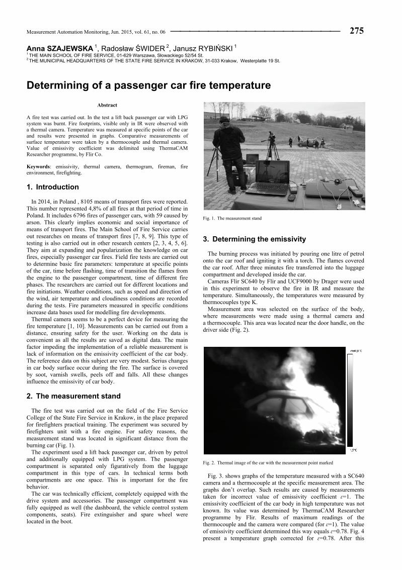
Measurement area was selected on the surface of the body, where measurements were made using a thermal camera and a thermocouple. This area was located near the door handle, on the driver side (Fig. 2).
Fig. 2. Thermal image of the car with the measurement point marked
Fig. 3. shows graphs of the temperature measured with a SC640
camera and a thermocouple at the specific measurement area. The graphs don’t overlap. Such results are caused by measurements taken for incorrect value of emissivity coefficient ɛ=1. The emissivity coefficient of the car body in high temperature was not known. Its value was determined by ThermaCAM Researcher programme by Flir. Results of maximum readings of the thermocouple and the camera were compared (for ɛ=1). The value of emissivity coefficient determined this way equals ɛ=0.78. Fig. 4 present a temperature graph corrected for ɛ=0.78. After this
276 Measurement Automation Monitoring, Jun. 2015, vol. 61, no. 06
procedure a good correlation between the results gathered from the camera and the thermocouple was achieved. This indicates that the emissivity coefficient was calculated correctly.
Fig. 3. Graph of the car body temperature [°C ] measured by a thermocouple and
a camera, for ɛ=1
Fig. 4. Graph of the car body temperature [°C ] measured by a thermocouple and
a camera, for ɛ=0.78
4. Fire footprints in IR
Gusts of wind caused the flames overshadow the measurement area, interfering with the measurement. It turned out that the camera is very useful for recording various events taking place during combustion. They leave traces in the form of temperature peaks.
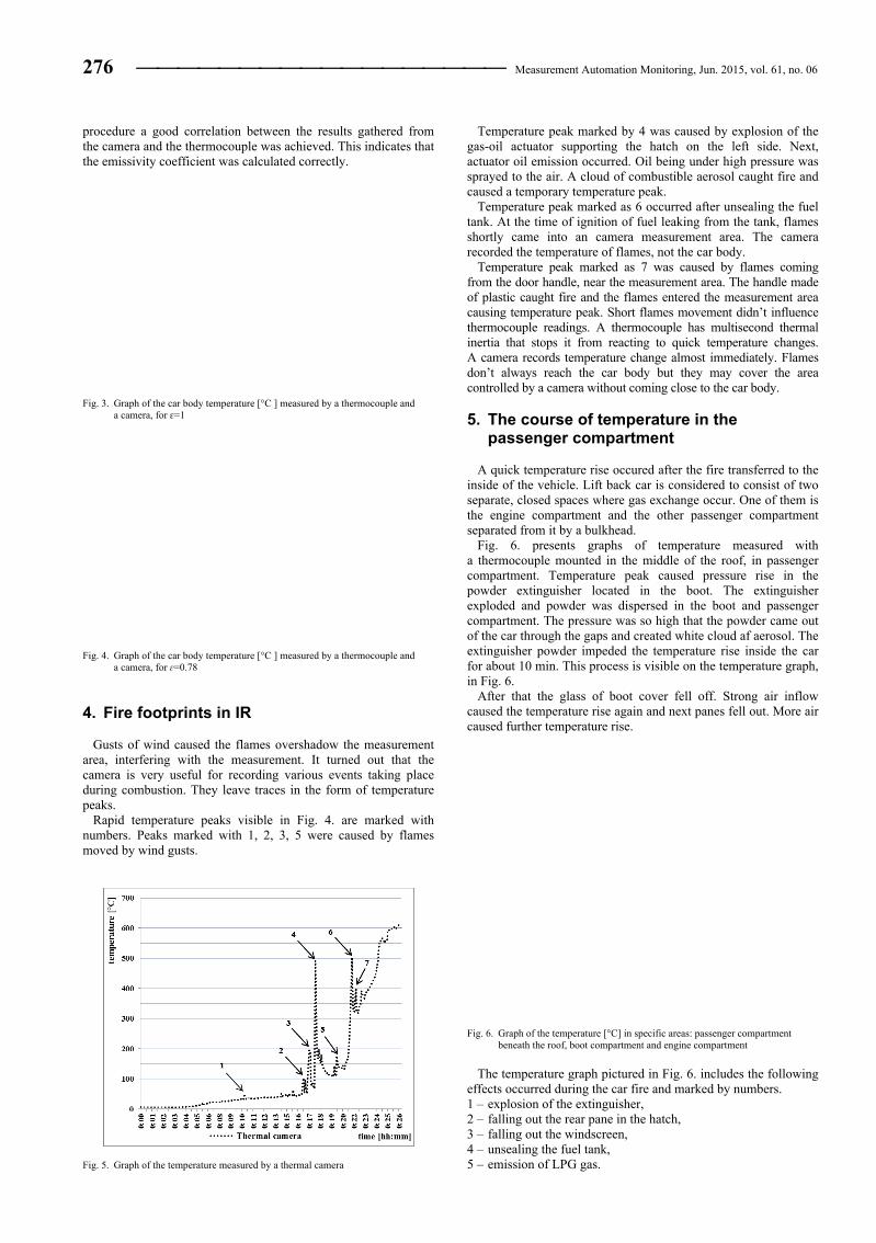
Rapid temperature peaks visible in Fig. 4. are marked with numbers. Peaks marked with 1, 2, 3, 5 were caused by flames moved by wind gusts.
Fig. 5. Graph of the temperature measured by a thermal camera
Temperature peak marked by 4 was caused by explosion of the gas-oil actuator supporting the hatch on the left side. Next, actuator oil emission occurred. Oil being under high pressure was sprayed to the air. A cloud of combustible aerosol caught fire and caused a temporary temperature peak.
Temperature peak marked as 6 occurred after unsealing the fuel tank. At the time of ignition of fuel leaking from the tank, flames shortly came into an camera measurement area. The camera recorded the temperature of flames, not the car body.
Temperature peak marked as 7 was caused by flames coming from the door handle, near the measurement area. The handle made of plastic caught fire and the flames entered the measurement area causing temperature peak. Short flames movement didn’t influence thermocouple readings. A thermocouple has multisecond thermal inertia that stops it from reacting to quick temperature changes. A camera records temperature change almost immediately. Flames don’t always reach the car body but they may cover the area controlled by a camera without coming close to the car body. 5. The course of temperature in the
passenger compartment
A quick temperature rise occured after the fire transferred to the inside of the vehicle. Lift back car is considered to consist of two separate, closed spaces where gas exchange occur. One of them is the engine compartment and the other passenger compartment separated from it by a bulkhead.
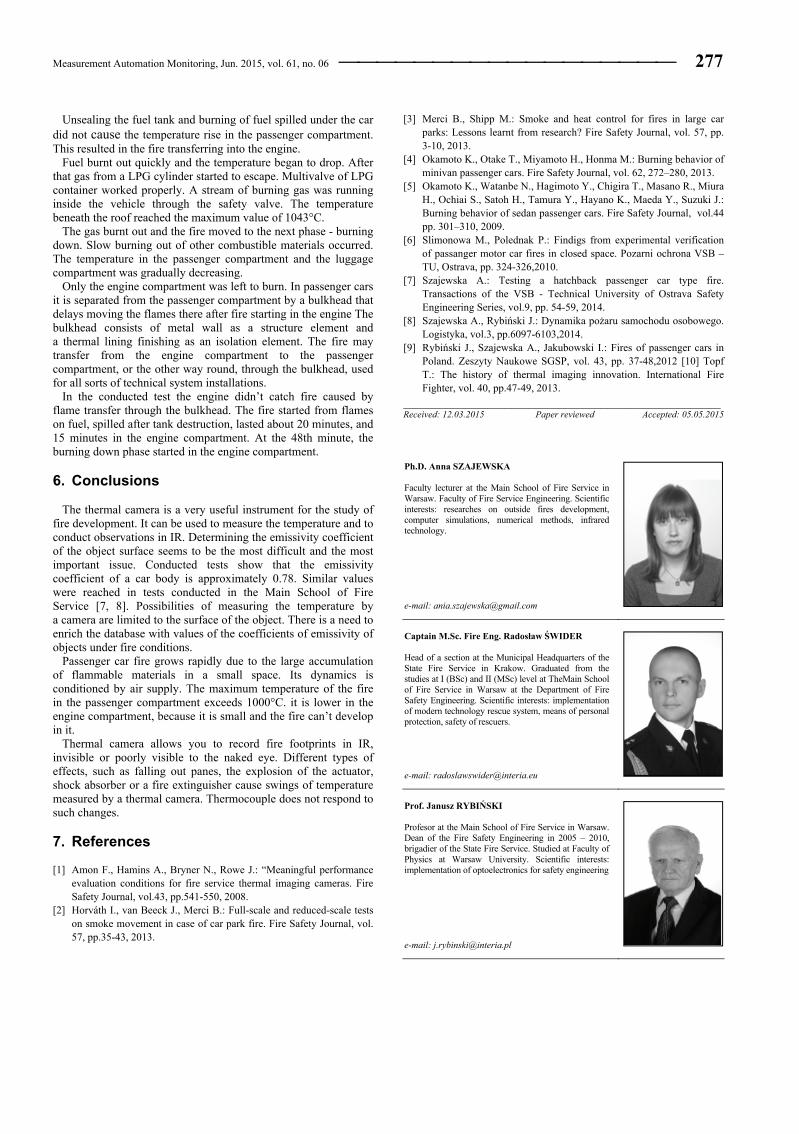
Fig. 6. presents graphs of temperature measured with a thermocouple mounted in the middle of the roof, in passenger compartment. Temperature peak caused pressure rise in the powder extinguisher located in the boot. The extinguisher exploded and powder was dispersed in the boot and passenger compartment. The pressure was so high that the powder came out of the car through the gaps and created white cloud af aerosol. The extinguisher powder impeded the temperature rise inside the car for about 10 min. This process is visible on the temperature graph, in Fig. 6.
After that the glass of boot cover fell off. Strong air inflow caused the temperature rise again and next panes fell out. More air caused further temperature rise.
Fig. 6. Graph of the temperature [°C] in specific areas: passenger compartment
beneath the roof, boot compartment and engine compartment
The temperature graph pictured in Fig. 6. includes the following
effects occurred during the car fire and marked by numbers. 1 – explosion of the extinguisher, 2 – falling out the rear pane in the hatch, 3 – falling out the windscreen, 4 – unsealing the fuel tank, 5 – emission of LPG gas.
Measurement Automation Monitoring, Jun. 2015, vol. 61, no. 06 277
Unsealing the fuel tank and burning of fuel spilled under the car did not cause the temperature rise in the passenger compartment. This resulted in the fire transferring into the engine.
Fuel burnt out quickly and the temperature began to drop. After that gas from a LPG cylinder started to escape. Multivalve of LPG container worked properly. A stream of burning gas was running inside the vehicle through the safety valve. The temperature beneath the roof reached the maximum value of 1043°C.
The gas burnt out and the fire moved to the next phase - burning down. Slow burning out of other combustible materials occurred. The temperature in the passenger compartment and the luggage compartment was gradually decreasing.
Only the engine compartment was left to burn. In passenger cars it is separated from the passenger compartment by a bulkhead that delays moving the flames there after fire starting in the engine The bulkhead consists of metal wall as a structure element and a thermal lining finishing as an isolation element. The fire may transfer from the engine compartment to the passenger compartment, or the other way round, through the bulkhead, used for all sorts of technical system installations.
In the conducted test the engine didn’t catch fire caused by flame transfer through the bulkhead. The fire started from flames on fuel, spilled after tank destruction, lasted about 20 minutes, and 15 minutes in the engine compartment. At the 48th minute, the burning down phase started in the engine compartment. 6. Conclusions
The thermal camera is a very useful instrument for the study of fire development. It can be used to measure the temperature and to conduct observations in IR. Determining the emissivity coefficient of the object surface seems to be the most difficult and the most important issue. Conducted tests show that the emissivity coefficient of a car body is approximately 0.78. Similar values were reached in tests conducted in the Main School of Fire Service [7, 8]. Possibilities of measuring the temperature by a camera are limited to the surface of the object. There is a need to enrich the database with values of the coefficients of emissivity of objects under fire conditions.
Passenger car fire grows rapidly due to the large accumulation of flammable materials in a small space. Its dynamics is conditioned by air supply. The maximum temperature of the fire in the passenger compartment exceeds 1000°C. it is lower in the engine compartment, because it is small and the fire can’t develop in it.
Thermal camera allows you to record fire footprints in IR, invisible or poorly visible to the naked eye. Different types of effects, such as falling out panes, the explosion of the actuator, shock absorber or a fire extinguisher cause swings of temperature measured by a thermal camera. Thermocouple does not respond to such changes. 7. References [1] Amon F., Hamins A., Bryner N., Rowe J.: “Meaningful performance
evaluation conditions for fire service thermal imaging cameras. Fire Safety Journal, vol.43, pp.541-550, 2008.
[2] Horváth I., van Beeck J., Merci B.: Full-scale and reduced-scale tests on smoke movement in case of car park fire. Fire Safety Journal, vol. 57, pp.35-43, 2013.
[3] Merci B., Shipp M.: Smoke and heat control for fires in large car parks: Lessons learnt from research? Fire Safety Journal, vol. 57, pp. 3-10, 2013.
[4] Okamoto K., Otake T., Miyamoto H., Honma M.: Burning behavior of minivan passenger cars. Fire Safety Journal, vol. 62, 272–280, 2013.
[5] Okamoto K., Watanbe N., Hagimoto Y., Chigira T., Masano R., Miura H., Ochiai S., Satoh H., Tamura Y., Hayano K., Maeda Y., Suzuki J.: Burning behavior of sedan passenger cars. Fire Safety Journal, vol.44 pp. 301–310, 2009.
[6] Slimonowa M., Polednak P.: Findigs from experimental verification of passanger motor car fires in closed space. Pozarni ochrona VSB –TU, Ostrava, pp. 324-326,2010.
[7] Szajewska A.: Testing a hatchback passenger car type fire. Transactions of the VSB - Technical University of Ostrava Safety Engineering Series, vol.9, pp. 54-59, 2014.
[8] Szajewska A., Rybiński J.: Dynamika pożaru samochodu osobowego. Logistyka, vol.3, pp.6097-6103,2014.
[9] Rybiński J., Szajewska A., Jakubowski I.: Fires of passenger cars in Poland. Zeszyty Naukowe SGSP, vol. 43, pp. 37-48,2012 [10] Topf T.: The history of thermal imaging innovation. International Fire Fighter, vol. 40, pp.47-49, 2013.
_____________________________________________________ Received: 12.03.2015 Paper reviewed Accepted: 05.05.2015 Ph.D. Anna SZAJEWSKA Faculty lecturer at the Main School of Fire Service in Warsaw. Faculty of Fire Service Engineering. Scientific interests: researches on outside fires development, computer simulations, numerical methods, infrared technology. e-mail: [email protected]
Captain M.Sc. Fire Eng. Radosław ŚWIDER Head of a section at the Municipal Headquarters of the State Fire Service in Krakow. Graduated from the studies at I (BSc) and II (MSc) level at TheMain School of Fire Service in Warsaw at the Department of Fire Safety Engineering. Scientific interests: implementation of modern technology rescue system, means of personal protection, safety of rescuers. e-mail: [email protected]
Prof. Janusz RYBIŃSKI Profesor at the Main School of Fire Service in Warsaw. Dean of the Fire Safety Engineering in 2005 – 2010, brigadier of the State Fire Service. Studied at Faculty of Physics at Warsaw University. Scientific interests: implementation of optoelectronics for safety engineering e-mail: [email protected]