Embed Size (px)
Citation preview

Determination of thickness, refractive index, and spectral scattering of aninhomogeneous thin film with rough interfacesJ. Anto Pradeep and Pratima Agarwal Citation: J. Appl. Phys. 108, 043515 (2010); doi: 10.1063/1.3478706 View online: http://dx.doi.org/10.1063/1.3478706 View Table of Contents: http://jap.aip.org/resource/1/JAPIAU/v108/i4 Published by the American Institute of Physics. Additional information on J. Appl. Phys.Journal Homepage: http://jap.aip.org/ Journal Information: http://jap.aip.org/about/about_the_journal Top downloads: http://jap.aip.org/features/most_downloaded Information for Authors: http://jap.aip.org/authors
Downloaded 08 May 2013 to 146.201.208.22. This article is copyrighted as indicated in the abstract. Reuse of AIP content is subject to the terms at: http://jap.aip.org/about/rights_and_permissions
Determination of thickness, refractive index, and spectral scattering of aninhomogeneous thin film with rough interfaces
J. Anto Pradeep and Pratima Agarwala�
Department of Physics, Indian Institute of Technology Guwahati, Guwahati 781 039, India
�Received 28 May 2010; accepted 14 July 2010; published online 23 August 2010�
The magnitude of spectral transmittance and reflectance is affected by the presence ofinhomogeneity and interfacial roughness. Therefore, the methods, based on the magnitude ofspectral transmittance and reflectance, are not adequate for the determination of thickness andoptical constants of films with inhomogeneity and interfacial roughness. The present articleproposes a method for the determination of thickness and refractive index using only the positionsof the interference fringes in spectral transmittance and reflectance at two different angles ofincidence. The proposed method is verified through numerical simulations, which result in �1%error for the film thickness. The complete parametrical dependence of spectral transmittance andreflectance of inhomogeneous film with rough interfaces on a substrate have been worked out for thefilm on transparent and opaque substrates, respectively. The spectrum envelopes have been solvedsimultaneously and the mathematical formulae are given for the determination of spectral scatteringdue to inhomogeneity and interfacial roughness for both transmittance and reflectance cases.© 2010 American Institute of Physics. �doi:10.1063/1.3478706�
I. INTRODUCTION
Knowledge of optical constants �n ,k� is fundamental tothe understanding of processes that involve the interaction ofelectromagnetic waves with matter. Hence, the determinationof n and k has been the fundamental task in the optical char-acterizations of a material. Traditionally, for the determina-tion of n and k, the material is made as thin film, to observethe interference in spectral transmittance or reflectance.1–3 Ofno surprise, there exist numerous proposals for the analysisof the spectral data.4–16 Majority of the proposals inherentlyconsider either homogeneous films with optically smoothinterfaces4–10 or films with weak inhomogeneity �smooth re-fractive index profiles� and interfacial roughness, so that theincoherent scattering, due to inhomogeneity and interfacialroughness, is not dominant in the magnitude of spectraltransmittance or reflectance.11,12
In reality, the inhomogeneity and interfacial roughnessare inevitable in thin films. In literature, there are a few pro-posals for the spectral data analysis of films with moderateinhomogeneity and interfacial roughness.13–17 However,these proposals are applicable only for specific cases due tocertain limitations like requiring �i� optically thick films,15
�ii� additional measurements other than the spectral transmit-tance and reflectance, which may sometimes bedestructive,16 �iii� prior knowledge of dispersion of n and k,17
and �iv� prior knowledge of incoherent spectral scatteringdue to inhomogeneity and interfacial roughness.17 So, a gen-eral formalism is indeed necessary to determine the funda-mental optical parameters of an inhomogeneous film withrough interfaces without requiring any prior knowledge ofdispersion of n and k and spectral scattering.
Of practical interest, it is often a question on the quality
of thin films; to what degree the interfacial roughness orinhomogeneity persists in the thin film, and more impor-tantly, whether the persisting interfacial roughness or inho-mogeneity is acceptable to the application of interest. So, inaddition to the determination of optical parameters of an in-homogeneous film with rough interfaces, a method, whichcan also determine the effect of interfacial roughness andinhomogeneity on the magnitude of spectral transmittance orreflectance, is vital.
In this article, we propose a method for the determina-tion of dispersion of refractive index n��� and thickness d ofthin films from the interference in spectral transmittance andreflectance. The method is applicable for both homogeneousand inhomogeneous thin films without requiring any priorknowledge of dispersion of n and k. Also, for inhomoge-neous films, the method is successful in determining the scat-tering profiles without requiring a search for the scatteringtheory that would presumably fit for the inhomogeneous sys-tem under consideration.
II. THEORY
A. Waves at rough interfaces and in aninhomogeneous medium
Specular reflectance and transmittance of an electromag-netic wave from a smooth interface, separating the medium iand j, can be given by Fresnel’s coefficients rij and tij, re-spectively. In the case of rough interface, the specular reflec-tance rij� and the transmittance tij�, in the amplitude, are givenby18
rij� = �1/2rij, �1a�
tij� = �1/2tij, �1b�
where �1/2 is the modulation in the amplitude due to interfa-cial roughness. �1/2, in general, is a complex number; the reala�Electronic mail: [email protected].
JOURNAL OF APPLIED PHYSICS 108, 043515 �2010�
0021-8979/2010/108�4�/043515/9/$30.00 © 2010 American Institute of Physics108, 043515-1
Downloaded 08 May 2013 to 146.201.208.22. This article is copyrighted as indicated in the abstract. Reuse of AIP content is subject to the terms at: http://jap.aip.org/about/rights_and_permissions
part corresponds to the fraction of coherent radiation in thedirection of normal propagation and the imaginary part cor-responds to the surface diffraction. For systems, where theinterfacial roughness shows no regularity, as in Fig. 1, �1/2 isa real and positive number. Henceforth, the discussions oninterfacial roughness would be based on the systems thatshow no regularity in roughness. In such systems, the inten-sity equivalent of �1/2 is denoted as �, the interfacial modu-lation coefficient, which corresponds to the intensity of co-herent radiation in the direction of normal propagation. Then,the term �1−�� would signify both the loss of coherency andmagnitude in the direction of normal propagation at the in-terface. The values of � would lie between 1 and 0 �1 is fora smooth interface and 0 is for a rough interface where thereis a total loss of coherence�.
The intensity of propagating electromagnetic wave, in aninhomogeneous medium, is given by19,20
I = I0 exp�− �extd� , �2�
where I0 is the intensity at the entrance of the medium, �ext isextinction coefficient, which is the sum of absorption andvolume scattering coefficients �a and �s, respectively, i.e.,
�ext=�a+�s and d is the depth of penetration. The volumescattering coefficient �s would correspond to the loss of bothcoherency and magnitude in the direction of normal propa-gation. Unlike �, �s is not bound. However, there exists alower bound—zero, which is for a homogeneous medium.For an inhomogeneous medium, �s is a positive nonzeronumber.
B. Mathematical expressions of transmittance andreflectance for a film-substrate system
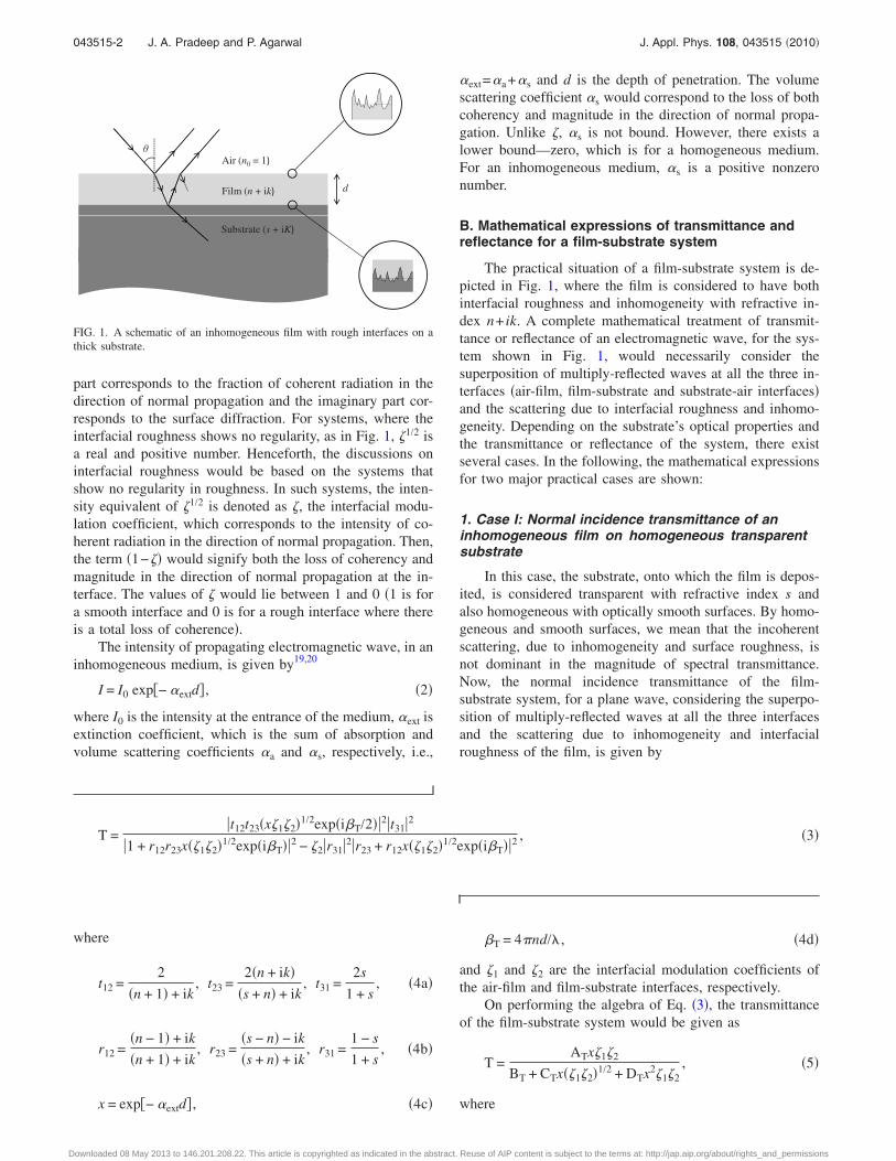
The practical situation of a film-substrate system is de-picted in Fig. 1, where the film is considered to have bothinterfacial roughness and inhomogeneity with refractive in-dex n+ ik. A complete mathematical treatment of transmit-tance or reflectance of an electromagnetic wave, for the sys-tem shown in Fig. 1, would necessarily consider thesuperposition of multiply-reflected waves at all the three in-terfaces �air-film, film-substrate and substrate-air interfaces�and the scattering due to interfacial roughness and inhomo-geneity. Depending on the substrate’s optical properties andthe transmittance or reflectance of the system, there existseveral cases. In the following, the mathematical expressionsfor two major practical cases are shown:
1. Case I: Normal incidence transmittance of aninhomogeneous film on homogeneous transparentsubstrate
In this case, the substrate, onto which the film is depos-ited, is considered transparent with refractive index s andalso homogeneous with optically smooth surfaces. By homo-geneous and smooth surfaces, we mean that the incoherentscattering, due to inhomogeneity and surface roughness, isnot dominant in the magnitude of spectral transmittance.Now, the normal incidence transmittance of the film-substrate system, for a plane wave, considering the superpo-sition of multiply-reflected waves at all the three interfacesand the scattering due to inhomogeneity and interfacialroughness of the film, is given by
T =�t12t23�x�1�2�1/2exp�i�T/2��2�t31�2
�1 + r12r23x��1�2�1/2exp�i�T��2 − �2�r31�2�r23 + r12x��1�2�1/2exp�i�T��2, �3�
where
t12 =2
�n + 1� + ik, t23 =
2�n + ik��s + n� + ik
, t31 =2s
1 + s, �4a�
r12 =�n − 1� + ik
�n + 1� + ik, r23 =
�s − n� − ik
�s + n� + ik, r31 =
1 − s
1 + s, �4b�
x = exp�− �extd� , �4c�
�T = 4�nd/� , �4d�
and �1 and �2 are the interfacial modulation coefficients ofthe air-film and film-substrate interfaces, respectively.
On performing the algebra of Eq. �3�, the transmittanceof the film-substrate system would be given as
T =ATx�1�2
BT + CTx��1�2�1/2 + DTx2�1�2, �5�
where
Film (n + ik
Air (n0 = 1
d
Substrate (s + iK
FIG. 1. A schematic of an inhomogeneous film with rough interfaces on athick substrate.
043515-2 J. A. Pradeep and P. Agarwal J. Appl. Phys. 108, 043515 �2010�
Downloaded 08 May 2013 to 146.201.208.22. This article is copyrighted as indicated in the abstract. Reuse of AIP content is subject to the terms at: http://jap.aip.org/about/rights_and_permissions
AT = 64s2�n2 + k2� ,
BT = ��n + 1�2 + k2����s + n�2 + k2��s + 1�2 − ��s − n�2 + k2��2�s − 1�2� ,
CT = ��n2 + k2 − 1��s2 − n2 − k2���s + 1�2 − �2�s − 1�2� + 4k2s��s + 1�2 + �2�s − 1�2��2 cos �T − �k�s2 − n2 − k2���s + 1�2 − �2�s
− 1�2� − ks�n2 + k2 − 1���s + 1�2 + �2�s − 1�2��4 sin �T,
DT = ��n − 1�2 + k2����s − n�2 + k2��s + 1�2 − ��s + n�2 + k2��2�s − 1�2� .
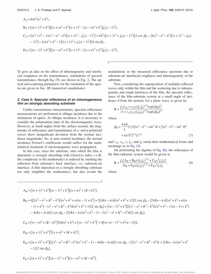
To give an idea on the effect of inhomogeneity and interfa-cial roughness on the transmittance, simulations of spectraltransmittance, through Eq. �5�, are shown in Fig. 2. The op-tical and scattering parameters for the simulation of the spec-tra are given in Sec. III �numerical simulations�.
2. Case II: Specular reflectance of an inhomogeneousfilm on strongly absorbing substrate
Unlike transmittance measurements, specular reflectancemeasurements are performed at oblique incidence due to thelimitations of optics. At oblique incidence, it is necessary toconsider the polarization state of the electromagnetic wave.However, at small angles from the surface normal, the mag-nitudes of reflectance and transmittance of s- and p-polarizedwaves show insignificant deviation from the normal inci-dence magnitudes. So, at near normal incidence, the normalincidence Fresnel’s coefficients would suffice for the math-ematical treatment of electromagnetic wave propagation.
In this case, since the substrate, onto which the film isdeposited, is strongly absorbing with refractive index s+ iK,the complexity in the mathematics is reduced by omitting thereflection from substrate’s back interface, i.e., substrate-airinterface. A film deposited on a strongly absorbing substratenot only simplifies the mathematics, but also avoids the
modulations in the measured reflectance spectrum due tosubstrate-air interfacial roughness and inhomogeneity of thesubstrate.
Now, considering the superposition of multiply-reflectedwaves only within the film and the scattering due to inhomo-geneity and rough interfaces of the film, the specular reflec-tance of the film-substrate system at a small angle of inci-dence � from the normal, for a plane wave, is given by
R =�1�r12 + r23x��1�2�1/2exp�i�R��2
�1 + r12r23x��1�2�1/2exp�i�R��2, �6�
where
�R =4�d
��1/2��n2 − k2 − sin2 �� + ��n2 − k2 − sin2 ��2
+ 4n2k2�1/2��1/2 �7�
and r12, r23, x, �1, and �2 retain their mathematical forms andmeanings as in Eq. �3�.
On performing the algebra of Eq. �6�, the reflectance ofthe film-substrate system would be given as
R =�1�AR + BRx��1�2�1/2 + CRx2�1�2�
DR + ERx��1�2�1/2 + FRx2�1�2, �8�
where
AR = ��n + 1�2 + k2���n − 1�2 + k2���s + n�2 + �K + k�2� ,
BR = 4���s2 − n2 + K2 − k2���n2 + k2 + n��n − 1� + k2� + 2��Kn − ks�k�n2 + k2 + 1���2 cos �R − �2�Kn − ks���n2 + k2 + n��n
− 1� + k2� − �s2 − n2 + K2 − k2�k�n2 + k2 + 1��2 sin �R� + ��n − 1�2 + k2����s2 − n2 + K2 − k2���n2 + k2 − 1��n − 1� + k2�
− 4�Kn − ks�k�2 cos �R − �2�Kn − ks��n2 + k2 − 1� − 2�s2 − n2 + K2 − k2�k�2 sin �R� ,
CR = ��s − n�2 + �K − k�2��16�n2 + k2� + ��n − 1�2 + k2�2 + 8��n��n − 1�2 + k2�n − 2��� ,
DR = ��n + 1�2 + k2�2��s + n�2 + �K + k�2� ,
ER = ��n + 1�2 + k2����s2 − n2 + K2 − k2��n2 + k2 − 1� − 4�Kn − ks�k�2 cos �R − �2�s2 − n2 + K2 − k2�k + 2�Kn − ks��n2 + k2
− 1��2 sin �R� ,
FR = ��n + 1�2 + k2���n − 1�2 + k2���s − n�2 + �K − k�2� .
043515-3 J. A. Pradeep and P. Agarwal J. Appl. Phys. 108, 043515 �2010�
Downloaded 08 May 2013 to 146.201.208.22. This article is copyrighted as indicated in the abstract. Reuse of AIP content is subject to the terms at: http://jap.aip.org/about/rights_and_permissions
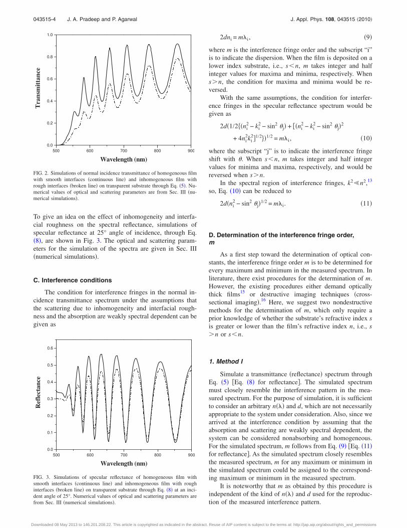
To give an idea on the effect of inhomogeneity and interfa-cial roughness on the spectral reflectance, simulations ofspecular reflectance at 25° angle of incidence, through Eq.�8�, are shown in Fig. 3. The optical and scattering param-eters for the simulation of the spectra are given in Sec. III�numerical simulations�.
C. Interference conditions
The condition for interference fringes in the normal in-cidence transmittance spectrum under the assumptions thatthe scattering due to inhomogeneity and interfacial rough-ness and the absorption are weakly spectral dependent can begiven as
2dni = m�i , �9�
where m is the interference fringe order and the subscript “i”is to indicate the dispersion. When the film is deposited on alower index substrate, i.e., s�n, m takes integer and halfinteger values for maxima and minima, respectively. Whensn, the condition for maxima and minima would be re-versed.
With the same assumptions, the condition for interfer-ence fringes in the specular reflectance spectrum would begiven as
2d�1/2��ni2 − ki
2 − sin2 �j� + ��ni2 − ki
2 − sin2 �j�2
+ 4ni2ki
2�1/2��1/2 = m�i , �10�
where the subscript “j” is to indicate the interference fringeshift with �. When s�n, m takes integer and half integervalues for minima and maxima, respectively, and would bereversed when sn.
In the spectral region of interference fringes, k2n2,13
so, Eq. �10� can be reduced to
2d�ni2 − sin2 �j�1/2 = m�i . �11�
D. Determination of the interference fringe order,m
As a first step toward the determination of optical con-stants, the interference fringe order m is to be determined forevery maximum and minimum in the measured spectrum. Inliterature, there exist procedures for the determination of m.However, the existing procedures either demand opticallythick films15 or destructive imaging techniques �cross-sectional imaging�.16 Here, we suggest two nondestructivemethods for the determination of m, which only require aprior knowledge of whether the substrate’s refractive index sis greater or lower than the film’s refractive index n, i.e., sn or s�n.
1. Method I
Simulate a transmittance �reflectance� spectrum throughEq. �5� �Eq. �8� for reflectance�. The simulated spectrummust closely resemble the interference pattern in the mea-sured spectrum. For the purpose of simulation, it is sufficientto consider an arbitrary n��� and d, which are not necessarilyappropriate to the system under consideration. Also, since wearrived at the interference condition by assuming that theabsorption and scattering are weakly spectral dependent, thesystem can be considered nonabsorbing and homogeneous.For the simulated spectrum, m follows from Eq. �9� �Eq. �11�for reflectance�. As the simulated spectrum closely resemblesthe measured spectrum, m for any maximum or minimum inthe simulated spectrum could be assigned to the correspond-ing maximum or minimum in the measured spectrum.
It is noteworthy that m as obtained by this procedure isindependent of the kind of n��� and d used for the reproduc-tion of the measured interference pattern.
500 600 700 800 9000.0
0.2
0.4
0.6
0.8
1.0T
rans
mitt
ance
Wavelength (nm)
FIG. 2. Simulations of normal incidence transmittance of homogeneous filmwith smooth interfaces �continuous line� and inhomogeneous film withrough interfaces �broken line� on transparent substrate through Eq. �5�. Nu-merical values of optical and scattering parameters are from Sec. III �nu-merical simulations�.
500 600 700 800 9000.0
0.1
0.2
0.3
0.4
0.5
0.6
Ref
lect
ance
Wavelength (nm)
FIG. 3. Simulations of specular reflectance of homogeneous film withsmooth interfaces �continuous line� and inhomogeneous film with roughinterfaces �broken line� on transparent substrate through Eq. �8� at an inci-dent angle of 25°. Numerical values of optical and scattering parameters arefrom Sec. III �numerical simulations�.
043515-4 J. A. Pradeep and P. Agarwal J. Appl. Phys. 108, 043515 �2010�
Downloaded 08 May 2013 to 146.201.208.22. This article is copyrighted as indicated in the abstract. Reuse of AIP content is subject to the terms at: http://jap.aip.org/about/rights_and_permissions
2. Method II
Unlike the previous method, which is applicable in allregions of spectral interference, this method is applicableonly in optically thin region of the spectrum, i.e., the regionof lower interference orders.
Consider the interference conditions in the normal inci-dence transmittance spectrum for two adjacent interferenceorders
2dn1 = ��1, �12�
2dn2 = �� − 0.5��2, �13�
where � is the interference order, which is to be determined.From Eqs. �12� and �13�, � is given as
� =0.5�2
��2 − �1�−
2d�n1 − n2���2 − �1�
. �14�
In optically thin region of the spectrum, the denominator ofsecond term, in Eq. �14�, is several times greater than thenumerator, and so Eq. �14� can be reduced to
�0 =0.5�2
��2 − �1�, �15�
where the subscript “0” is to indicate the approximation.�0 is clearly an overestimate of �. However, since we
already know whether a particular interference order is inte-ger or half integer �from the knowledge of whether sn ors�n�, the nearest lower integer or half integer is the inter-ference order � for the particular fringe.
E. Determination of film thickness, d
For the determination of d, minimum two spectral mea-surements with different angles of incidence, in the spectralregion of interference fringes, are required. When the film isdeposited on a transparent substrate, a normal incidencetransmittance and an oblique incidence specular reflectancewould suffice for the determination of d. When the film isdeposited on an opaque substrate, specular reflectance at twodifferent angles of incidence can be considered. In the fol-lowing, we would show the necessary mathematical relationsfor a film on a transparent substrate considering the spectralmeasurements—normal incidence transmittance and obliqueincidence specular reflectance. �Necessary mathematical re-lations for the determination of d with the specular reflec-tance measurements at two different angles of incidence aregiven in Appendix�
Considering an interference fringe order, say �, the in-terference conditions in normal incidence transmittance andspecular reflectance at �I, following Eqs. �9� and �11�, re-spectively, would be given as
2dn1 = ��1 �transmittance� , �16�
2d�n12 + � − sin2 �I�1/2 = ��2 �reflectance� , �17�
where � compensates the dispersion of refractive index be-tween �1 and �2.
From Eqs. �16� and �17�, d would be given as
d = �2��12 − �2
2�4�sin2 �I − ��1/2
. �18�
Since Eq. �18� contains an undetermined parameter �, d isnot calculable from Eq. �18�. If �=0, then, Eq. �18� reducesto
d0 = �2��12 − �2
2�4 sin2 �I
1/2
, �19�
where the subscript “0” is to indicate the approximation.Now, d0 is although calculable and a close estimate of d,
it can only be considered as a first step in the determinationof d. A better estimation of d can be made through Eq. �18�once � is found.
For the determination of �, consider the interferencecondition, adjacent to the interference fringe order �, in thenormal incidence transmittance, which follows from Eq. �9�as
2d�n12 + �1/2 = �� + 0.5��3 �transmittance� , �20�
where compensates the dispersion of refractive index be-tween �1 and �3.
From Eqs. �16� and �20�, would be given by
=�� + 0.5�2�3
2 − �2�12
4d2 . �21�
In the spectral region of interference fringes �k2n2�, thenormal dispersion of refractive index can be given as
ni2 = G +
H
�ip , �22�
where G, H, and p are constants whose values depend on thematerial and the subscript “i” is used to indicate the disper-sion.
Then, � would be given by
� = �3
p��2p − �1
p��2
p��3p − �1
p�. �23�
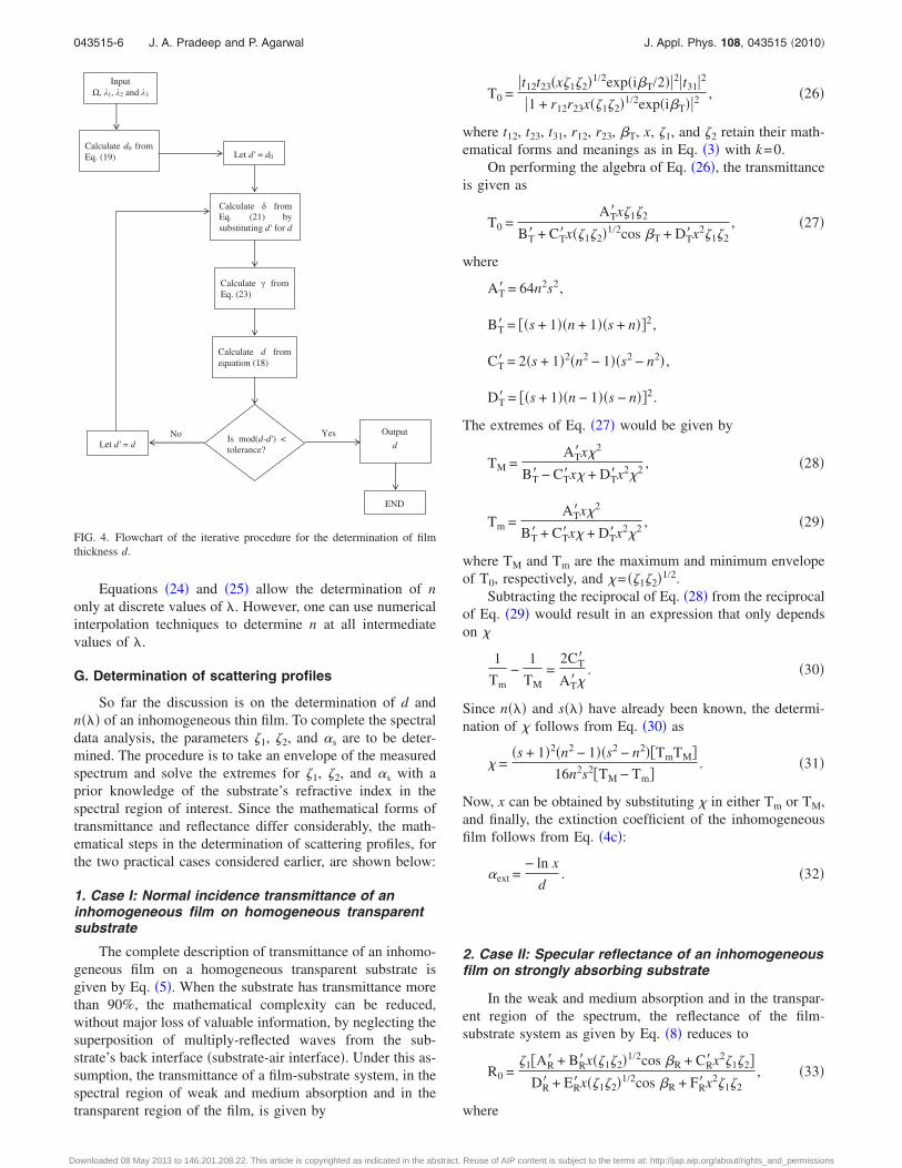
Having shown the necessary mathematical relations, the de-termination of d is made by an iterative procedure. The flow-chart of the iteration is shown in Fig. 4.
F. Determination of the real part of the refractiveindex, n
Now, for normal incidence spectral transmittance, n fol-lows from Eq. �9� as
ni =m�i
2d�24�
and for specular reflectance at an angle of incidence �j, nfollows from Eq. �11� as
ni = m2�i2
4d2 + sin2 �j1/2
, �25�
where d is the thickness of the film as obtained from theiterative procedure.
043515-5 J. A. Pradeep and P. Agarwal J. Appl. Phys. 108, 043515 �2010�
Downloaded 08 May 2013 to 146.201.208.22. This article is copyrighted as indicated in the abstract. Reuse of AIP content is subject to the terms at: http://jap.aip.org/about/rights_and_permissions
Equations �24� and �25� allow the determination of nonly at discrete values of �. However, one can use numericalinterpolation techniques to determine n at all intermediatevalues of �.
G. Determination of scattering profiles
So far the discussion is on the determination of d andn��� of an inhomogeneous thin film. To complete the spectraldata analysis, the parameters �1, �2, and �s are to be deter-mined. The procedure is to take an envelope of the measuredspectrum and solve the extremes for �1, �2, and �s with aprior knowledge of the substrate’s refractive index in thespectral region of interest. Since the mathematical forms oftransmittance and reflectance differ considerably, the math-ematical steps in the determination of scattering profiles, forthe two practical cases considered earlier, are shown below:
1. Case I: Normal incidence transmittance of aninhomogeneous film on homogeneous transparentsubstrate
The complete description of transmittance of an inhomo-geneous film on a homogeneous transparent substrate isgiven by Eq. �5�. When the substrate has transmittance morethan 90%, the mathematical complexity can be reduced,without major loss of valuable information, by neglecting thesuperposition of multiply-reflected waves from the sub-strate’s back interface �substrate-air interface�. Under this as-sumption, the transmittance of a film-substrate system, in thespectral region of weak and medium absorption and in thetransparent region of the film, is given by
T0 =�t12t23�x�1�2�1/2exp�i�T/2��2�t31�2
�1 + r12r23x��1�2�1/2exp�i�T��2, �26�
where t12, t23, t31, r12, r23, �T, x, �1, and �2 retain their math-ematical forms and meanings as in Eq. �3� with k=0.
On performing the algebra of Eq. �26�, the transmittanceis given as
T0 =AT�x�1�2
BT� + CT�x��1�2�1/2cos �T + DT�x2�1�2, �27�
where
AT� = 64n2s2,
BT� = ��s + 1��n + 1��s + n��2,
CT� = 2�s + 1�2�n2 − 1��s2 − n2� ,
DT� = ��s + 1��n − 1��s − n��2.
The extremes of Eq. �27� would be given by
TM =AT�x�2
BT� − CT�x� + DT�x2�2 , �28�
Tm =AT�x�2
BT� + CT�x� + DT�x2�2 , �29�
where TM and Tm are the maximum and minimum envelopeof T0, respectively, and �= ��1�2�1/2.
Subtracting the reciprocal of Eq. �28� from the reciprocalof Eq. �29� would result in an expression that only dependson �
1
Tm−
1
TM=
2CT�
AT��. �30�
Since n��� and s��� have already been known, the determi-nation of � follows from Eq. �30� as
� =�s + 1�2�n2 − 1��s2 − n2��TmTM�
16n2s2�TM − Tm�. �31�
Now, x can be obtained by substituting � in either Tm or TM,and finally, the extinction coefficient of the inhomogeneousfilm follows from Eq. �4c�:
�ext =− ln x
d. �32�
2. Case II: Specular reflectance of an inhomogeneousfilm on strongly absorbing substrate
In the weak and medium absorption and in the transpar-ent region of the spectrum, the reflectance of the film-substrate system as given by Eq. �8� reduces to
R0 =�1�AR� + BR�x��1�2�1/2cos �R + CR�x2�1�2�
DR� + ER�x��1�2�1/2cos �R + FR�x2�1�2, �33�
where
Calculate fromEq. (21) bysubstituting d' for d
Let d' = d0
Calculate d0 fromEq. (19)
Calculate ! fromEq. (23)
Calculate d fromequation (18)
Is mod(d-d') <tolerance?Let d' = d
No
END
Outputd
Yes
Input", 1, 2 and 3
FIG. 4. Flowchart of the iterative procedure for the determination of filmthickness d.
043515-6 J. A. Pradeep and P. Agarwal J. Appl. Phys. 108, 043515 �2010�
Downloaded 08 May 2013 to 146.201.208.22. This article is copyrighted as indicated in the abstract. Reuse of AIP content is subject to the terms at: http://jap.aip.org/about/rights_and_permissions
AR� = �n2 − 1�2��s + n�2 + K2� ,
BR� = ��s − n�2 + K2��4n + �n − 1�2�2,
CR� = �n2 − 1��s2 − n2 + K2��4n + �n − 1�2� ,
DR� = �n + 1�4��s + n�2 + K2� ,
ER� = �n + 1�2�n2 − 1���s − n�2 + K2� ,
FR� = �n2 − 1�2�s2 − n2 + K2� ,
�R =4�d
��n2 − sin2 ��1/2,
and �, x, �1, and �2 retain their meanings as in Eq. �8�.The extremes of Eq. �33� would be given by
RM =�1�AR� + BR�� + CR��2�
DR� + ER�� + FR��2 , �34�
Rm =�1�AR� − BR�� + CR��2�
DR� − ER�� + FR��2 , �35�
where
� = x��1�2�1/2, �36�
and RM and Rm are the maximum and minimum envelope ofR0, respectively.
Dividing Eq. �34� by Eq. �35� would result in an expres-sion that depends only on �
RM
Rm=
�AR� + BR�� + CR��2��DR� − ER�� + FR��2��AR� − BR�� + CR��2��DR� + ER�� + FR��2�
. �37�
Rearranging the terms in Eq. �37� would result in a fourthorder polynomial in �. Solving the polynomial would resultfour mathematically allowed forms for �. Since � must be areal and positive number, lying in the range 0���1, thecorrect form of � could readily be obtained when the spectraldependence of all the four mathematically allowed forms of� are known.
Now, substitute the correct form of � in either Rm or RM
and solve the resulting expression for �1.Since � is a product of all the scattering terms and the
absorption, for any arbitrary inhomogeneous film with roughinterfaces, the procedure is successful only in determining �1
with no interference from �2 and �s. However, when theinterfacial roughness at both the film interfaces �air-film andfilm-substrate interfaces� are identical, i.e., �1=�2=�, the ex-tinction coefficient of the film follows from Eqs. �36� and�4c�
�ext =1
dln
�
�. �38�
The above procedures are successful only to the point ofdetermining �ext, and not separately �a and �s. It is because,in an inhomogeneous medium, the scattering and absorptionare so involved that it is impossible to separately identify the
contributions due to absorption and scattering from the ex-tinction coefficient.
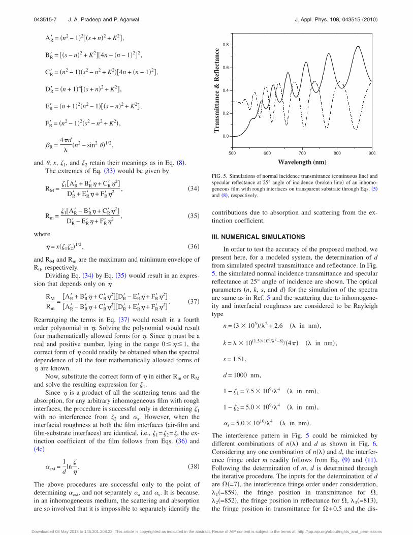
III. NUMERICAL SIMULATIONS
In order to test the accuracy of the proposed method, wepresent here, for a modeled system, the determination of dfrom simulated spectral transmittance and reflectance. In Fig.5, the simulated normal incidence transmittance and specularreflectance at 25° angle of incidence are shown. The opticalparameters �n, k, s, and d� for the simulation of the spectraare same as in Ref. 5 and the scattering due to inhomogene-ity and interfacial roughness are considered to be Rayleightype
n = �3 � 105�/�2 + 2.6 �� in nm� ,
k = � � 10�1.5�106/�2−8�/�4�� �� in nm� ,
s = 1.51,
d = 1000 nm,
1 − �1 = 7.5 � 109/�4 �� in nm� ,
1 − �2 = 5.0 � 109/�4 �� in nm� ,
�s = 5.0 � 1010/�4 �� in nm� .
The interference pattern in Fig. 5 could be mimicked bydifferent combinations of n��� and d as shown in Fig. 6.Considering any one combination of n��� and d, the interfer-ence fringe order m readily follows from Eq. �9� and �11�.Following the determination of m, d is determined throughthe iterative procedure. The inputs for the determination of dare ��=7�, the interference fringe order under consideration,�1�=859�, the fringe position in transmittance for �,�2�=852�, the fringe position in reflectance for �, �3�=813�,the fringe position in transmittance for �+0.5 and the dis-
500 600 700 800 900
0.0
0.2
0.4
0.6
0.8
Tra
nsm
ittan
ce&
Ref
lect
ance
Wavelength (nm)
FIG. 5. Simulations of normal incidence transmittance �continuous line� andspecular reflectance at 25° angle of incidence �broken line� of an inhomo-geneous film with rough interfaces on transparent substrate through Eqs. �5�and �8�, respectively.
043515-7 J. A. Pradeep and P. Agarwal J. Appl. Phys. 108, 043515 �2010�
Downloaded 08 May 2013 to 146.201.208.22. This article is copyrighted as indicated in the abstract. Reuse of AIP content is subject to the terms at: http://jap.aip.org/about/rights_and_permissions
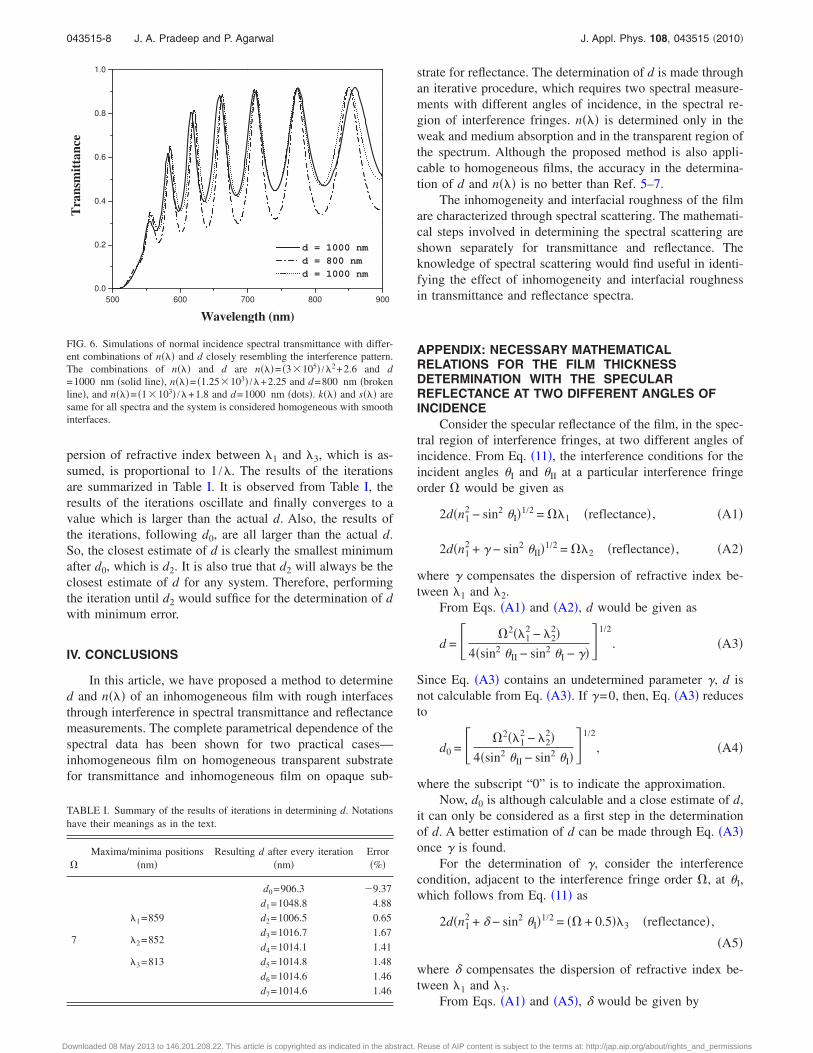
persion of refractive index between �1 and �3, which is as-sumed, is proportional to 1 /�. The results of the iterationsare summarized in Table I. It is observed from Table I, theresults of the iterations oscillate and finally converges to avalue which is larger than the actual d. Also, the results ofthe iterations, following d0, are all larger than the actual d.So, the closest estimate of d is clearly the smallest minimumafter d0, which is d2. It is also true that d2 will always be theclosest estimate of d for any system. Therefore, performingthe iteration until d2 would suffice for the determination of dwith minimum error.
IV. CONCLUSIONS
In this article, we have proposed a method to determined and n��� of an inhomogeneous film with rough interfacesthrough interference in spectral transmittance and reflectancemeasurements. The complete parametrical dependence of thespectral data has been shown for two practical cases—inhomogeneous film on homogeneous transparent substratefor transmittance and inhomogeneous film on opaque sub-
strate for reflectance. The determination of d is made throughan iterative procedure, which requires two spectral measure-ments with different angles of incidence, in the spectral re-gion of interference fringes. n��� is determined only in theweak and medium absorption and in the transparent region ofthe spectrum. Although the proposed method is also appli-cable to homogeneous films, the accuracy in the determina-tion of d and n��� is no better than Ref. 5–7.
The inhomogeneity and interfacial roughness of the filmare characterized through spectral scattering. The mathemati-cal steps involved in determining the spectral scattering areshown separately for transmittance and reflectance. Theknowledge of spectral scattering would find useful in identi-fying the effect of inhomogeneity and interfacial roughnessin transmittance and reflectance spectra.
APPENDIX: NECESSARY MATHEMATICALRELATIONS FOR THE FILM THICKNESSDETERMINATION WITH THE SPECULARREFLECTANCE AT TWO DIFFERENT ANGLES OFINCIDENCE
Consider the specular reflectance of the film, in the spec-tral region of interference fringes, at two different angles ofincidence. From Eq. �11�, the interference conditions for theincident angles �I and �II at a particular interference fringeorder � would be given as
2d�n12 − sin2 �I�1/2 = ��1 �reflectance� , �A1�
2d�n12 + � − sin2 �II�1/2 = ��2 �reflectance� , �A2�
where � compensates the dispersion of refractive index be-tween �1 and �2.
From Eqs. �A1� and �A2�, d would be given as
d = �2��12 − �2
2�4�sin2 �II − sin2 �I − ��1/2
. �A3�
Since Eq. �A3� contains an undetermined parameter �, d isnot calculable from Eq. �A3�. If �=0, then, Eq. �A3� reducesto
d0 = �2��12 − �2
2�4�sin2 �II − sin2 �I�
1/2
, �A4�
where the subscript “0” is to indicate the approximation.Now, d0 is although calculable and a close estimate of d,
it can only be considered as a first step in the determinationof d. A better estimation of d can be made through Eq. �A3�once � is found.
For the determination of �, consider the interferencecondition, adjacent to the interference fringe order �, at �I,which follows from Eq. �11� as
2d�n12 + − sin2 �I�1/2 = �� + 0.5��3 �reflectance� ,
�A5�
where compensates the dispersion of refractive index be-tween �1 and �3.
From Eqs. �A1� and �A5�, would be given by
TABLE I. Summary of the results of iterations in determining d. Notationshave their meanings as in the text.
�
Maxima/minima positions�nm�
Resulting d after every iteration�nm�
Error�%�
7
d0=906.3 �9.37d1=1048.8 4.88
�1=859 d2=1006.5 0.65
�2=852d3=1016.7 1.67d4=1014.1 1.41
�3=813 d5=1014.8 1.48d6=1014.6 1.46d7=1014.6 1.46
500 600 700 800 9000.0
0.2
0.4
0.6
0.8
1.0T
rans
mitt
ance
Wavelength (nm)
d = 1000 nmd = 800 nmd = 1000 nm
FIG. 6. Simulations of normal incidence spectral transmittance with differ-ent combinations of n��� and d closely resembling the interference pattern.The combinations of n��� and d are n���= �3�105� /�2+2.6 and d=1000 nm �solid line�, n���= �1.25�103� /�+2.25 and d=800 nm �brokenline�, and n���= �1�103� /�+1.8 and d=1000 nm �dots�. k��� and s��� aresame for all spectra and the system is considered homogeneous with smoothinterfaces.
043515-8 J. A. Pradeep and P. Agarwal J. Appl. Phys. 108, 043515 �2010�
Downloaded 08 May 2013 to 146.201.208.22. This article is copyrighted as indicated in the abstract. Reuse of AIP content is subject to the terms at: http://jap.aip.org/about/rights_and_permissions
=�� + 0.5�2�3
2 − �2�12
4d2 . �A6�
Assuming the dispersion of refractive index is proportionalto 1 /�p between �1 and �3, � would be given by
� = �3
p��2p − �1
p��2
p��3p − �1
p�. �A7�
1J. F. Hall, Jr. and W. F. C. Ferguson, J. Opt. Soc. Am. 45, 714 �1955�.2P. R. Wessel, Phys. Rev. 153, 836 �1967�.3G. D. Cody, C. R. Wronski, B. Abeles, R. B. Stephens, and B. Brooks,Sol. Cells 2, 227 �1980�.
4J. C. Manifacier, J. Gasiot, and J. P. Fillard, J. Phys. E 9, 1002 �1976�.5R. Swanepoel, J. Phys. E 16, 1214 �1983�.6D. B. Kushev, N. N. Zheleva, Y. Demakopoulou, and D. Siapkas, InfraredPhys. 26, 385 �1986�.
7D. A. Minkov, J. Phys. D: Appl. Phys. 22, 199 �1989�.8D. P. Arndt, R. M. A. Azzam, J. M. Bennett, J. P. Borgogno, C. K.
Carniglia, W. E. Case, J. A. Dobrowolski, U. J. Gibson, T. T. Hart, F. C.Ho, V. A. Hodgkin, W. P. Klapp, H. A. Macleod, E. Pelletier, M. K.Purvis, D. M. Quinn, D. H. Strome, R. Swenson, P. A. Temple, and T. F.Thonn, Appl. Opt. 23, 3571 �1984�.
9Rusli and G. A. J. Amaratunga, Appl. Opt. 34, 7914 �1995�.10S. D. Ventura, E. G. Birgin, J. M. Martínez, and I. Chambouleyron, J.
Appl. Phys. 97, 043512 �2005�.11B. Bovard, F. J. V. Milligen, M. J. Messerly, S. G. Saxe, and H. A.
Macleod, Appl. Opt. 24, 1803 �1985�.12L. De Caro and M. C. Ferrara, Thin Solid Films 342, 153 �1999�.13M. Nowak, Thin Solid Films 254, 200 �1995�.14J. C. Martínez-Antón, Appl. Opt. 39, 4557 �2000�.15J. C. Martínez-Antón and E. Bernabeu, Opt. Commun. 132, 321 �1996�.16A. Wolf, B. Terheiden, and R. Brendel, J. Appl. Phys. 104, 033106 �2008�.17M. Montecchi, R. M. Montereali, and E. Nichelatti, Thin Solid Films 396,
262 �2001�.18A. Ishimaru, Wave Propagation and Scattering in Random Media �Aca-
demic, New York, 1978�, Vol. 2, p. 463.19F. A. Jenkins and H. E. White, Fundamentals of Optics, 4th ed. �McGraw-
Hill, Singapore, 1981�, p. 458.20C. F. Klingshirn, Semiconductor Optics �Springer-Verlag, Berlin, 1997�, p.
35.
043515-9 J. A. Pradeep and P. Agarwal J. Appl. Phys. 108, 043515 �2010�
Downloaded 08 May 2013 to 146.201.208.22. This article is copyrighted as indicated in the abstract. Reuse of AIP content is subject to the terms at: http://jap.aip.org/about/rights_and_permissions