Embed Size (px)
Citation preview

The
Jour
nal o
f Exp
erim
enta
l Bio
logy
© 2014. Published by The Company of Biologists Ltd | The Journal of Experimental Biology (2014) 217, 3677-3687 doi:10.1242/jeb.105114
3677
ABSTRACTAdhesive organs like arolia of insects allow these animals to climb ondifferent substrates by creating high adhesion forces. According tothe Dahlquist criterion, adhesive organs must be very soft, exhibitingan effective Young’s modulus of below 100 kPa to adhere well tosubstrates. Such a low effective Young’s modulus allows theadhesive organs to make almost direct contact with the substrate andresults in van der Waals forces along with capillary forces. In previousstudies, the effective Young’s moduli of adhesive organs weredetermined using indentation tests, revealing their structure to be verysoft. However, adhesive organs show a layered structure, thus themeasured values comprise the effective Young’s moduli of severallayers of the adhesive organs. In this study, a new approach isillustrated to measure the Young’s modulus of the outermost layer ofthe arolium, i.e. of the epicuticle, of the stick insect Carausiusmorosus. As a result of the epicuticle being supported by uprightfibres, tensile tests allow the determination of the Young’s modulusof the epicuticle with hardly influence from subjacent layers. In ourtensile tests, arolia of stick insects adhering on a latex membranewere stretched by stretching the membrane while the elongation ofthe contact area between an arolium and the membrane wasrecorded. For analysis, mathematical models of the mechanicalsystem were developed. When fed with the observed elongations,these models yield estimates for the Young’s modulus of theepicuticle of approximately 100 MPa. Thus, in arolia, a very thin layer(~225 nm) of a rather stiff material, which is less susceptible toabrasion, makes contact with the substrates, whereas the innerfibrous structure of arolia is responsible for their softness.
KEY WORDS: Finite element simulation, Cuticle, Adhesion, Stickinsects, Arolium, Carausius morosus.
INTRODUCTIONMany insects possess specialised attachment organs on their tarsi,which enable them to climb and even walk upside down on almost
RESEARCH ARTICLE
1Department Cellular Neurobionics, Institute for Biology II, RWTH AachenUniversity, Worringerweg 3, 52074 Aachen, Germany. 2Westfälisches Institut fürBionik, Westfälische Hochschule Gelsenkirchen Bocholt Recklinghausen,Münsterstraße 265, 46397 Bocholt, Germany. 3Central Facility for ElectronMicroscopy, RWTH Aachen University, Ahornstraße 55, 52074 Aachen, Germany.4Institute of Biomedical Mechatronics, University of Linz, Altenbergerstraße 69,4040 Linz, Austria.
*Author for correspondence ([email protected])
This is an Open Access article distributed under the terms of the Creative CommonsAttribution License (http://creativecommons.org/licenses/by/3.0), which permits unrestricteduse, distribution and reproduction in any medium provided that the original work is properlyattributed.
Received 7 March 2014; Accepted 7 August 2014
all substrates. Some species are even capable of resisting extremepull-off and shear forces equivalent to more than 100 times theirown body weight (Eisner and Aneshansley, 2000; Federle et al.,2000), and to move with a high velocity. The detailed underlyingmechanisms of this impressive performance are still unclear, butthey are presumably based on a combination of a complexultrastructure and the physical properties of the adhesive organs.
Adhesive organs in arthropods and vertebrates have beenclassified into ‘smooth’ pads with a soft cuticle (e.g. arolia) and‘hairy’ pads (Beutel and Gorb, 2001). The cuticle of the arolium ofCarausius morosus Sinéty 1901 differs structurally from typical hardexoskeleton cuticles and from the soft and flexible cuticles found injoints and extensible body parts. In arolia, the fibres in the procuticleare neither orientated parallel nor perpendicular to the surface, butthey are oriented in a specific angle to it (Scholz et al., 2008;Bennemann et al., 2011).
Adhesion between smooth pads and a surface is mainlydetermined by two forces: capillarity forces caused by a liquid layer(‘wet adhesion’) and van der Waals forces. Van der Waals forces areonly achieved at nearly direct contact between pad and surface (theliquid layer has to be <10 nm) (Kendall, 2001; Dirks and Federle,2011). For such close contact, adhesive organs have to be veryresilient.
The adhesion performance of arthropods and vertebrates hasaroused high interest in biologists and engineers trying to createartificial reusable adhesion devices (Gorb et al., 2007; Shen et al.,2008; Röhrig et al., 2012). To transfer the functionality of adhesiveorgans into technical devices, it is important to determine themechanical properties of the materials from which adhesive organsare composed. Until now, the mechanical properties of only a fewmaterials in adhesive organs were known (Peattie et al., 2007;Bullock and Federle, 2009). In previous studies, analyses of themechanical properties of smooth adhesive organs have beenperformed using indentation tests (Gorb et al., 2000; PerezGoodwyn et al., 2006; Scholz et al., 2008; Scholz et al., 2009;Barnes et al., 2011). Indentation tests of layered structures have thedisadvantage that subjacent layers – and in the case of adhesiveorgans also their hydroflation, i.e. their filling with liquid – have animpact on the measurement of superficial layers. This means that inindentation tests not only the Young´s modulus of the layer, whichwas indented, is determined, but the effective Young´s modulus ofthe uppermost and several layers below is also measured.Simplified, in indentation tests, the effective Young’s modulus of alllayers down to approximately tenfold of the indentation depth ismeasured. In previous studies on the Young’s moduli of the adhesiveorgans of C. morosus and Litoria caerulea (Scholz et al., 2008,Scholz et al., 2009), an indentation depth of approximately 1 μm ledto an effective Young’s modulus for the combination of cuticulin,
Determination of the Young’s modulus of the epicuticle of thesmooth adhesive organs of Carausius morosus using tensiletestingMichael Bennemann1,2,*, Stefan Backhaus1, Ingo Scholz1, Daesung Park3, Joachim Mayer3 and Werner Baumgartner1,4
The
Jour
nal o
f Exp
erim
enta
l Bio
logy
3678
epicuticle and procuticle layer in C. morosus and to an effectiveYoung’s modulus of the uppermost cell layers in L. caerulae.
In this study, we are especially interested in the Young’s modulusof the outermost layer of the arolium, the so called epicuticle, whichcontacts the substrate and mediates the adhesion. To determine theYoung’s modulus of the epicuticle, we used tensile tests, in whichforces are acting almost exclusively on the outermost layer of thearolia. A further advantage of tensile tests is that the Young’smodulus can be determined in different orientations. This isimportant for the measurement of anisotropic structures, such as theadhesive organs of stick insects (Scholz et al., 2008).
The aim of our study was to characterise the detailedultrastructure responsible for the mechanical properties of thearolium of C. morosus and to develop a new method to determinethe Young’s modulus of soft superficial biological membranes, suchas the epicuticle, with less impact from the underlying layers aspresent in indentation tests.
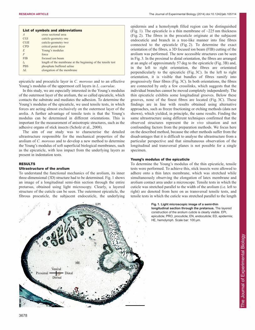
RESULTSUltrastructure of the aroliumTo understand the functional mechanics of the arolium, its innerthree-dimensional (3D) structure had to be determined. Fig. 1 showsan image of a longitudinal semi-thin section through the entirepretarsus, obtained using light microscopy. Clearly, a layeredstructure of the cuticle can be seen. The outermost epicuticle, thefibrous procuticle, the subjacent endocuticle, the underlying
epidermis and a hemolymph filled region can be distinguished(Fig. 1). The epicuticle is a thin membrane of ~225 nm thickness(Fig. 2). The fibres in the procuticle originate at the subjacentendocuticle and branch in a tree-like manner into fine fibresconnected to the epicuticle (Fig. 2). To determine the exactorientation of the fibres, a 3D focused ion beam (FIB) cutting of thearolium was performed. The now accessible structures can be seenin Fig. 3. In the proximal to distal orientation, the fibres are arrangedat an angle of approximately 57 deg to the epicuticle (Fig. 3B) and,in the left to right orientation, the fibres are orientatedperpendicularly to the epicuticle (Fig. 3C). In the left to rightorientation, it is visible that bundles of fibres ramify intoprogressively finer fibres (Fig. 3C). In both orientations, the fibresare connected by only a few crosslinks, which suggests that theindividual branches cannot be moved completely independently. Thethin epicuticle exhibits some longitudinal grooves. Below thesegrooves, none of the finest fibres are located (Fig. 3C). Thesefindings are in line with results obtained using alternativeapproaches, such as freeze fractioning or etching methods (data notshown), which yielded, in principle, the same results. Finding thesame ultrastructure using different techniques confirmed that theobserved structures represent the in vivo situation and notconfounding factors from the preparation methods. We focus hereon the described method, because the other methods suffer from thedisadvantages that it is difficult to analyse the ultrastructure from aparticular perspective and that simultaneous observation of thelongitudinal and transversal planes is not possible for a singlespecimen.
Young’s modulus of the epicuticleTo determine the Young’s modulus of the thin epicuticle, tensiletests were performed. To achieve this, stick insects were allowed toadhere onto a thin latex membrane, which was stretched whilesimultaneously observing the elongation of latex membrane andarolium contact area under a microscope. Tensile tests in which thecuticle was stretched parallel to the width of the arolium (i.e. left toright) are denoted from here on as transversal tensile tests, andtensile tests in which the cuticle was stretched parallel to the length
RESEARCH ARTICLE The Journal of Experimental Biology (2014) doi:10.1242/jeb.105114
List of symbols and abbreviationsA cross sectional areaCGI cuticle-geometry oneCGII cuticle-geometry twoCPD critical point dryerE Young’s modulusF forceFIB focused ion beaml0 length of the membrane at the beginning of the tensile testPBS phosphate buffered salineΔL elongation of the membrane
Fig. 1. Light microscopic image of a semi-thinlongitudinal section through the pretarsus. The layeredconstruction of the arolium cuticle is clearly visible. EPI,epicuticle; PRO, procuticle; EN, endocuticle; ED, epidermis;HE, hemolymph. Scale bar: 100 μm.

The
Jour
nal o
f Exp
erim
enta
l Bio
logy
of the arolium (i.e. distal to proximal) are denoted from here on aslongitudinal tensile tests. To determine the elongation of the contactarea and the latex membrane during transversal or longitudinaltensile tests, the length of the contact area and the distance betweentwo reference points on the latex membrane were measured at thebeginning and end of the tensile tests (Fig. 4) and at two time pointsin between. Eleven transversal tensile tests were included in theevaluation (Table 1). In all of these tensile tests, the contact area ofthe arolium did not change its position relative to the referencepoints on the latex membrane. Furthermore, no structures of thelatex membrane, which had been under the arolium contact area atthe beginning of the stretching, appeared next to the arolium contactarea during stretching (Fig. 4). This means that the arolium did notslide during the experiments. Furthermore, there were no largechanges in the angle between the tarsi and the contact areas duringstretching, and no large changes of the contours of the aroliumcontact areas occurred during stretching. If slipping, turning oractive movement of a stick insect occurred, the correspondingexperiments were excluded from the evaluation.
In the transversal direction, the procuticle fibres were notstretched but bent, thus hardly influencing the force needed tostretch the arolium, whereas the stretching of the epicuticle yieldedthe highest impact.
In the transversal tensile tests, the latex membrane was stretchedby up to 121.8% [±3.3% (s.d.), N=11, Table 1] of the initial length,resulting in a coupled, perfectly linear stretching of the aroliumwhen the latex membrane was stretched more than approximately10% of the total stretching of 21.8%. At elongations less than 10%,the epicuticle exhibited a smaller apparent stiffness, most probablyrepresenting the flattening of the grooves seen in the unstretchedarolium. At higher levels of strain, the behaviour was linear,indicating a homogeneous linear elastic material. At full expansionof the latex membrane (121.8%), the cuticle adhering on the latexmembrane was stretched to approximately 112.0% (±3.7%, N=11,Table 1), which corresponded to an elongation of 55.8% (±14.9%,N=11, Table 1) of the elongation of the latex membrane.
In longitudinal tensile tests, the arolium contact area increasedonly very little or not at all in length, and often the orientation of thetarsus to the contact area changed greatly, resulting in a deformed
3679
RESEARCH ARTICLE The Journal of Experimental Biology (2014) doi:10.1242/jeb.105114
Fig. 2. Final branching of the fibres in the procuticle. Scanning electronmicroscopic image of a semi-thin sagittal section from which the epoxy resinwas etched off. The thinnest branches of the fibres in the procuticle and theirconnection to the adjacent epicuticle can be seen. Scale bar: 2 μm.
Fig. 3. Secondary electron images of the fibrous inner structure of thearolium. (A) Overview of a rectangular cut into an arolium prepared byfocused ion beam (FIB). (B) Fibrous structure in the proximal to distalorientation. The fibres are orientated in an angle of approximately 57 deg tothe epicuticle. (C) Fibrous structure in the left to right orientation. The fibresare orientated perpendicular to the epicuticle. Bundles of fibres ramify intoprogressively finer fibres. The image was taken in an angle of 82 deg to thecutting edge. Scale bars: 10 μm (A), 5 μm (B), 10 μm (C).
The
Jour
nal o
f Exp
erim
enta
l Bio
logy
3680
contact area. These findings are in line with the ultrastructure,because, owing to the angular orientation of the fibres in theprocuticle, a stretching of these fibres would be necessary during astretching of the arolium in the longitudinal direction. Therefore, werefrained from determining the Young’s modulus of the epicuticle inthe longitudinal direction.
The latex membrane was initially characterised and found toexhibit a thickness of 60 μm and a Young’s modulus of 1.2 MPa(±0.008 MPa, N=3, in supplementary material Table S1; Fig. S1).
These values in combination with the observed linearity of theelongations of the arolium and the latex membrane allow for a roughestimation of the Young’s modulus of the arolium: assuming bothmaterials have a linear elasticity, and neglecting the influence of thelayers subjacent to the epicuticle and imperfections of the straintransmission due to geometric restrictions, one can calculate
with Ecut being the Young’s modulus of the epicuticle, dlatex thethickness of the latex membrane (=60 μm), dcut the thickness of theepicuticle (=0.4 μm), Elatex being the Young’s modulus of the latexmembrane (=1.2 MPa), εfree being the strain (relative elongation) ofthe free latex membrane (=0.208, transversal test 4) and εcut beingthe strain in the contact zone between the latex membrane andarolium (=0.106, transversal test 4). Using the example of the tensiletest transversal four, this yields a Young’s modulus ofEcut=173.2 MPa.
To take into account the effects of the layers subjacent to theepicuticle and of the complicated geometry of the arolium contactarea, finite element simulations were performed adjusting theYoung’s modulus of the epicuticle to fit the experimentalobservations. Two different models were used. The first, cuticle-geometry one (CGI), comprised only the thin epicuticle showing auniform Young’s modulus and the contour of the arolium contactarea. The second, cuticle-geometry two (CGII), consisted of theepicuticle supported by a thicker, soft layer comprising the layerssubjacent to the epicuticle and both being surrounded by the cuticleof the non-contacting areas of the arolium. These two modelscomprise the extreme cases, and the exact Young’s modulus shouldbe somewhere in between the found values. The finite elementsimulations for the first four transversal tensile tests resulted in thefollowing Young’s moduli: the Young’s modulus of the epicuticles
≈ ⋅ ⋅ ε − εε
Edd
E ( ),cut
latex
cut
latex free cut
cut
with CGI had to be adjusted on 173.4 MPa (±135.8 MPa, N=4,Fig. 5; Table 2) and the epicuticles with CGII had to be adjusted on27.3 MPa (±26.2 MPa, N=4, Fig. 5; Table 2).
The finite element simulations of the first four tensile testsshowed for both models a linear relationship between the relativepercentage elongations of the epicuticle (percentage elongation ofthe epicuticle divided by the percentage elongation of the latexmembrane) in relation to the determined Young’s moduli(supplementary material Fig. S2). This is in line with theexperimental observations and allowed the determination of theYoung’s moduli of the seven further tensile tests based on the resultsof the finite elements simulations of the first four tensile tests. Thisestimation resulted in the Young’s moduli denoted in Table 2.
Combining the Young’s moduli determined by finite elementsimulation and the Young’s moduli estimated by using the results ofthe finite element simulations resulted in the following Young’smoduli for the different cuticle geometries (Fig. 6; Table 2): CGI,329.9 MPa (±174.9 MPa, N=11); CGII, 58.7 MPa (±34.8 MPa,N=11). The simple analytical approximation derived above yielded168.6 MPa (±106.4 MPa, N=11).
DISCUSSIONAdhesive organs of climbing animals exhibit remarkable abilitieswith respect to adhesion and friction force generation incombination with rapid detachment. In order to adhere well ontodifferent substrates, adhesive organs need to fulfil differentrequirements. According to the Dahlquist criterion (Dahlquist,1966), materials are tacky when their Young’s modulus is lower thanapproximately 100 kPa. The overall Young’s moduli of adhesiveorgans from different species, i.e. the stress–strain relationship oftheir whole composite structure, were found previously to exhibitsuch low stiffnesses through characterising their Young’s moduliusing indentation tests (Gorb et al., 2000; Perez Goodwyn et al.,2006; Scholz et al., 2008; Scholz et al., 2009; Barnes et al., 2011).However, if adhesive organs consisted of a material with a Young’smodulus of 100 kPa or below, they would be very susceptible towear. We assume that such a low effective modulus of the wholestructure can still be achieved when the adhesive organs are coveredwith a thin membrane with a high Young’s modulus, so long as thesubjacent structure shows a high softness. Such adhesive organsconsisting of a soft core covered with a stiffer membrane combineconformability to the surface roughness with resilience to the
RESEARCH ARTICLE The Journal of Experimental Biology (2014) doi:10.1242/jeb.105114
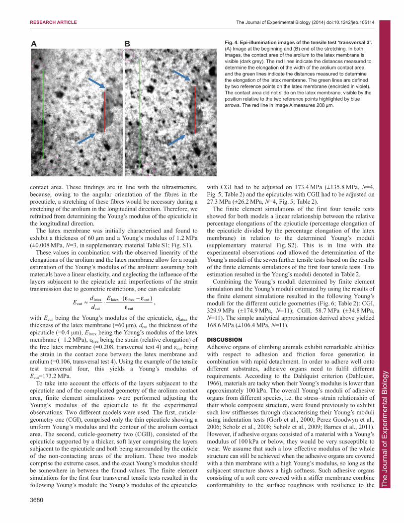
A B Fig. 4. Epi-illumination images of the tensile test ‘transversal 3’.(A) Image at the beginning and (B) end of the stretching. In bothimages, the contact area of the arolium to the latex membrane isvisible (dark grey). The red lines indicate the distances measured todetermine the elongation of the width of the arolium contact area,and the green lines indicate the distances measured to determinethe elongation of the latex membrane. The green lines are definedby two reference points on the latex membrane (encircled in violet).The contact area did not slide on the latex membrane, visible by theposition relative to the two reference points highlighted by bluearrows. The red line in image A measures 208 μm.

The
Jour
nal o
f Exp
erim
enta
l Bio
logy
environment (Perez Goodwyn et al., 2006). This still allowsadhesive organs to conform to surface asperities.
In the case of animal adhesion between smooth adhesive organsand a surface, a further factor has to be taken into account. An‘adhesive liquid’ produced by animals causes capillary forces andincreases adhesion forces in most cases (Dixon et al., 1990; Drechslerand Federle, 2006; Edwards and Tarkanian, 1970). Capillary forcesplay a major role in adhesion to rough surfaces, when surface cavitiesare filled up with the liquid. If the layer of liquid gets too thick,friction is reduced rapidly and adhesion is lost. To minimise the liquidlayer between adhesive organ and substrate, the adhesive organ has to
adapt very closely to the substrate, requiring a biological material witha low Young’s modulus (Drechsler and Federle, 2006; Federle et al.,2006; You and Wan, 2013). Despite the wet adhesion realised in theadhesive organs of stick insects in the evaluated tensile tests, we didnot find evidence for the arolium slipping on the latex membrane.This might be founded in the special non-Newtonian properties of theadhesive liquid and the very thin fluid layer, which let the adhesiveliquid act as a solid at lower forces (Drechsler and Federle, 2006;Dirks et al., 2010).
A thin coverage can better conform to rough substrates than a thickcoverage of the same material, when the thickness of the thin
3681
RESEARCH ARTICLE The Journal of Experimental Biology (2014) doi:10.1242/jeb.105114
Table 1. Widths of the arolium contact areas and the distances between two reference points on the latex membrane measured for the evaluation of the eleven transversal tensile tests at their beginnings and ends and at two time points in between
Tensile test Image Time during stretching (s)
Arolium width ( m)
Arolium elongation (%)
Latex membrane length ( m)
Latex membrane elongation (%)
Relationship between arolium width and latex membrane length
Relationship between arolium elongation and latex membrane elongation
Trans 1 1 0 102.1 100.0 443.0 100.0 23.0 0.0 2 15 106.2 104.1 461.8 104.2 23.0 95.6 3 34.5 113.2 110.8 497.1 112.2 22.8 88.8 4 56 121.5 119.0 555.5 125.4 21.9 75.0
Trans 2 1 0 128.1 100.0 570.1 100.0 22.5 0.0 2 10.5 135.8 106.0 602.8 105.7 22.5 104.7 3 20.5 140.6 109.8 638.5 112.0 22.0 81.5 4 32 145.4 113.5 679.7 119.2 21.4 70.4
Trans 3 1 0 208.0 100.0 467.1 100.0 44.5 0.0 2 16.5 220.0 105.8 503.6 107.8 43.7 73.9 3 34 234.0 112.5 543.7 116.4 43.0 76.2 4 46.5 247.0 118.7 575.6 123.2 42.9 80.6
Trans 4 1 0 169.5 100.0 602.8 100.0 27.9 0.0 2 11 177.2 104.5 623.1 103.4 28.4 135.5 3 31 183.0 108.0 681.8 113.1 26.8 60.7 4 48 187.4 110.6 728.0 120.8 25.7 50.9
Trans 5 1 0 176.5 100.0 668.3 100.0 26.1 0.0 2 11 184.9 104.7 708.8 106.1 26.1 78.4 3 26 187.8 106.4 755.0 113.0 24.9 49.2 4 43 191.3 108.4 816.6 122.2 23.4 37.9
Trans 6 1 0 158.4 100.0 620.2 100.0 25.5 0.0 2 19 166.2 104.9 683.7 110.2 24.3 48.1 3 32.5 172.0 108.6 731.9 118.0 23.5 47.6 4 45.5 172.0 108.6 782.0 126.1 22.0 32.9
Trans 7 1 0 161.1 100.0 639.4 100.0 25.2 0.0 2 13 168.5 104.6 656.8 102.7 25.7 169.8 3 30 172.4 107.0 724.2 113.3 23.8 52.8 4 52 182.3 113.2 801.2 125.3 22.8 52.0
Trans 8 1 0 162.7 100.0 779.4 100.0 20.9 0.0 2 16 166.6 102.4 818.6 105.0 20.4 47.1 3 34 177.7 109.2 884.3 113.5 20.1 68.1 4 42 179.1 110.1 907.8 116.5 19.7 61.0
Trans 9 1 0 160.1 100.0 752.4 100.0 21.3 0.0 2 16 167.6 104.6 787.7 104.7 21.3 98.6 3 39 173.1 108.1 837.8 111.4 20.7 71.0 4 57 175.0 109.3 871.8 115.9 20.1 58.3
Trans 10 1 0 167.3 100.0 579.1 100.0 28.9 0.0 2 11 170.5 101.9 617.3 106.6 27.6 28.3 3 26 175.3 104.7 670.2 115.7 26.1 30.1 4 39 182.0 108.8 713.9 123.3 25.5 37.7
Trans 11 1 0 123.3 100.0 543.7 100.0 22.7 0.0 2 11 124.9 101.3 576.8 106.1 21.7 21.8 3 20 129.7 105.2 604.3 111.1 21.5 47.0 4 38 138.4 112.3 661.1 121.6 20.9 56.8
Mean 45.4 174.7 112.0 735.7 121.8 24.2 55.8 Standard deviation 7.3 31.3 3.7 108.1 3.3 6.2 14.9 The percentage elongation of the arolium contact areas and the latex membrane are given, both normalised on 100% at the beginning of the stretchings. The means and the standard deviations refer to the values at the ends of the tensile tests. Trans, transversal tensile test.

The
Jour
nal o
f Exp
erim
enta
l Bio
logy
3682
coverage is smaller than the wavelength of the roughness of thesubstrate (Persson and Gorb, 2003; Gorb, 2008). Transferred to C.morosus, whose epicuticle has a thickness of approximately 225 nm,it should be able to adhere to substrates with asperities, which arefrom bottom to top higher than 225 nm, only by passively folding itsepicuticle around surface asperities during attachment. Thisconformation to the substrate might be supported by the fluid insidethe cuticle, which enables the membrane to follow the contours of thesubstrate to which the insect is adhering. For folding or bending, amuch higher Young’s modulus is tolerable than for elastic Hertz-deformation of a semi-infinite material. For biomimicry this meansthat it is favourable to produce artificial adhesion devices withpreferable thin terminating membranes of a higher Young’s modulus,which are supported by an underlying layer of lower stiffness.
The usage of tensile testing in place of indentation testing enabledthe determination of the Young’s modulus of the epicuticle itself,instead of the effective Young’s modulus of several layers of thearolium. Scholz et al. (Scholz et al., 2008) assumed that the stiffnessof the adhesive organs of stick insects increased with increasing depthof the cuticle. If this were the case, the fibrous procuticle would showa higher stiffness than the epicuticle. Especially in the directionparallel to the surface of the adhesive organs, this is unlikely becausethe fibres in the procuticle are orientated almost perpendicular to thisdirection and therefore cannot absorb tensile forces.
In indentation tests, the hydroflation of the pretarsus and,depending on the indentation depth, several layers of the cuticlehave an impact on the deformation behaviour of the adhesive organ,meaning that only the effective Young’s modulus of several layerscan be determined. In previous studies of stick insects (Scholz et al.,2008), an indentation of approximately 1 μm using a sharp atomicforce microscopy (AFM) cantilever is influenced not only by theepicuticle and outermost wax layer, but also by the subjacentprocuticle layer. In tensile testing, the hydroflation of the pretarsusis negligible because mainly the outer layers of the arolium have animpact on the deformation behaviour.
During the transversal tensile tests, first, the cuticle might be notstretched but only spread until the epicuticle no longer showedgrooves, which are normally present on the surface of the arolia.This is consistent with the observation that the cuticle was elongatedmore at the beginning of the tensile tests than at the end (Table 1).Based on the great extent of elongation of the epicuticle of 12%, itis safe to assume that the initial spreading of the epicuticle isnegligible for the determination of the Young’s modulus. The factthat the cuticle was stretched more at the beginning of the tensiletests indicates that the fibres in the procuticle do not have a highimpact on the force needed to stretch the epicuticle in the transversaldirection. The force needed to bend the fibres should be consistentfrom the beginning of the stretching. Assuming that the fibres have
RESEARCH ARTICLE The Journal of Experimental Biology (2014) doi:10.1242/jeb.105114
Fig. 5. Images of the finite element simulations of the tensile test transversal 3 using CGI and CGII. (A,B) CGI (top view), (C, D) CGII (side view), (A,C)non-deformed cuticle (green and red) on a latex membrane (grey), (B,D) deformed cuticle after stretching the latex membrane approximately 23.2%, and theadjustment of the Young’s modulus of the cuticle to B, 34.5 MPa; D, 2 MPa. The insets in C and D show details of the cuticle geometry. In C and D, thesurroundings of CGII are hidden to show the deformation of the thin epicuticle layer.

The
Jour
nal o
f Exp
erim
enta
l Bio
logy
a low impact on the tensile rigidity of the cuticle supports the highYoung’s moduli that were determined for the epicuticle throughtensile testing.
For the reasons listed above, the Young’s moduli determined inthis study are much higher than the effective Young’s moduli thathave been determined in previous studies (Gorb et al., 2000; Scholzet al., 2008). It has to be emphasised that this is a very robust result.Although we and others have found effective Young’s moduli ofseveral kilopascal by indentation testing in the past, the sound valuefor the epicuticle is in the range of several to a few hundredmegapascal. Even if there are some parameters that have not beeninvestigated here and might influence the findings, such as the exact
thickness of the cuticle layers, the influence of the surroundingtissue or the Poisson’s ratio of the materials, the general result is stillvalid. To analyse the influence of these parameters, we compiledfurther models beside the two finite element simulations and thesimple analytical approximation, and we varied the parameterswhich could have an influence. However, within the respectivemodels, we found in the worst cases deviations of a factor ofapproximately three, but definitely not three orders of magnitude.That the epicuticle shows a higher Young’s modulus than theunderlying cuticle layers is in agreement with previous studies(Perez Goodwyn et al., 2006; Gorb, 2008).
The ultrastructural analyses of the arolium enables new insightsinto the fibrous organisation of the procuticle. The angledarrangement of the fibres in the proximal to distal orientation mightlead to a higher tensile rigidity of the cuticle in this orientation thanin the left to right orientation where the fibres are arrangedperpendicularly to the epicuticle. This difference in tensile rigiditymight explain why the cuticles showed almost no elongation in thelongitudinal tensile test. In contrast to a previous study (PerezGoodwyn et al., 2006), fewer crosslinks between the fibres in theprocuticle were found in our study. Extensive crosslinks between thefibres would increase the force needed to stretch the cuticle.
The method to determine the Young’s modulus of biologicalsuperficial tissues by tensile testing is illustrated here for the firsttime, and refinements could enable us to achieve even more accuratevalues. For example, it would improve the accuracy of the methodto know the exact thickness of the epicuticle and the other cuticlelayers of the same stick insects as used in the tensile tests.
The determination of the Young’s modulus of the epicuticle of C.morosus using tensile testing demonstrates the feasibility ofanalysing the mechanical properties of soft superficial biologicaltissues using this method followed by analytical evaluation and/orfinite element simulation. The results support the assumption thatsmooth adhesive organs are covered with a very thin epicuticle of ahigh Young’s modulus, which is supported by a fibrous procuticle,which equips the adhesive organs with the required softness neededfor the conformation to a substrate. Biomimetic adhesive devicesfabricated using this design principle would have the advantage ofbeing less susceptible to contamination and abrasion.
MATERIALS AND METHODSStudy animalsStick insects (Carausius morosus, Phasmatidae) were taken from thelaboratory colony at the RWTH Aachen University, Institute for Biology II,Department Cellular Neurobionics.
Light and scanning electron microscopyAdult stick insects (565±95.1 mg, N=2) were stunned with CO2 anddecapitated. The tarsi of all six legs were cut off and were fixed in 0.5%glutaraldehyde (Merck, Darmstadt, Germany) and 2% formaldehyde(Merck, Darmstadt, Germany) in PBS (AppliChem, Darmstadt, Germany)at room temperature for 24 h. The samples were post-fixed for 1 h in 1%osmium tetroxide (Sigma-Aldrich, St Louis, MO, USA) in PBS andthereafter washed in distilled water (three times for 15 min). The tarsi weredehydrated in an increasing ethanol series (30%, 50%, 70% each for 15 min)and subsequently stained for 1 h with 2% uranyl acetate solution (Merck,Darmstadt, Germany) in 70% ethanol (Carl Roth, Karlsruhe, Germany) in adark environment. Subsequently, the samples were dehydrated in ethanol:70% (three times), 80%, 90%, 96% and 100% (twice), each for 15 min, andwashed twice for 30 min in propylene oxide (Serva, Heidelberg, Germany).They were then transferred to a mixture of propylene oxide and epoxy resin(Epon, Serva, Heidelberg, Germany) (1:1) from which the propylene oxideevaporated overnight. After washing in Epon (twice for 2 h), the sampleswere embedded in Epon, and the Epon was polymerised for 48 h at 60°C.
3683
RESEARCH ARTICLE The Journal of Experimental Biology (2014) doi:10.1242/jeb.105114
Table 2. Young’s moduli of the epicuticles of the stick insects usedin the first four tensile tests determined by finite elementsimulations and the Young’s moduli of the epicuticles of the stickinsect used in the tensile tests 5-11, estimated using the results ofthe finite element simulations of the first four tensile tests
Young’s Young’s Young’s modulus modulus modulus
Tensile tests CGI (MPa) CGII (MPa) analytical (MPa)
Trans 1 63.0 15.0 60.6Trans 2 223.0 21.0 76.0Trans 3 34.5 2.0 43.3Trans 4 373.0 71.0 173.2Trans 5 537.8 100.4 295.7Trans 6 596.0 112.0 366.3Trans 7 373.8 67.5 165.0Trans 8 269.1 46.5 114.0Trans 9 300.5 52.8 127.7Trans 10 540.2 100.8 296.6Trans 11 317.9 56.3 136.1Mean 329.9 58.7 168.6Standard deviation 174.9 34.8 106.4
Further, the Young’s moduli for all eleven transversal tensile tests determinedanalytically are given. Trans, transversal tensile test; CG, cuticle geometry.
1000
100
10
1
0.1
0.01
Youn
g’s
mod
ulus
(MP
a)
CGI CGII Analytical eYM
Fig. 6. Young’s moduli of the epicuticle in comparison to the effectiveYoung’s modulus of adhesive organs. The first three boxes show theYoung’s moduli of the epicuticle, as determined by tensile testing followed byfinite element simulation (CGI, CGII) or analytical determination (Analytical).The ends of the boxes define the 25th and 75th percentiles, with a line at themedian and error bars to the maximum and minimum values (without regardto outliers). Outliers were marked as points and are defined asZu=Q1–1.5*(Q3–Q1); Zo=Q3+1.5*(Q3–Q1) with Zu=outlier bottom, Zo=outliertop, Q1=25% quartile, Q3=75% quartile. The box furthest to the right showsthe effective Young’s moduli (eYM) of whole adhesive organs, as determinedby indentation testing. These Young’s moduli were adopted from Gorb et al.(Gorb et al., 2000), Perez Goodwyn et al. (Perez Goodwyn et al., 2006) andScholz et al. (Scholz et al., 2008). The Young’s modulus is plottedlogarithmically.

The
Jour
nal o
f Exp
erim
enta
l Bio
logy
3684
To analyse the layered structure of the cuticle of the arolium fromembedded tarsi semi-thin sections of 1 μm thickness were cut longitudinallyalong the symmetrical plane of the tarsus using a Reichert OmU3ultramicrotome (Reichert GmbH, Wien, Austria). The sections were attachedto coverslips, stained with Methylene Blue (Riedel-de Haën, Seelze,Germany) for 30 s and washed with distilled water. Finally, the sections weredried on a heating plate and mounted with Depex (Serva, Heidelberg,Germany) on glass slides. Images were taken with a Motic BA 400microscope (Motic Deutschland GmbH, Wetzlar, Germany) using aMoticam 3 and the Motic Images Plus 2.0 software at magnifications of×100, ×400 and ×1000 in a 2048×1536 pixel format.
To analyse the detailed ultrastructure of the procuticle and the epidermis,semi-thin sections (1 μm) with epoxy resin etched off were prepared. Forthis, an Epon-embedded tarsus was sectioned longitudinally at thesymmetrical plane of the tarsus with a Reichert OmU3 ultramicrotome usingglass knives. The sections were picked up on coverslips and kept on aheating plate at 60°C for 4 h. Subsequently, the sections were treated withsodium methanolate solution (315 ml sodium methoxide, Fluka, Buchs,Switzerland; 185 ml methanol, Carl Roth, Karlsruhe, Germany; 100 mltoluene, Fluka, Buchs, Switzerland) in the absence of air for 6 min,methanol-toluene solution (1:1) for 5 min, 2× acetone (AppliChem,Darmstadt, Germany) for 5 min and were then washed in distilled water for5 min in order to remove the resin. The samples were dehydrated withethanol: 30, 50, 70, 90, 100% (twice), each step was performed for 5 min,and the samples were gradually transferred into hexamethyldisilazane(HMDS): 30, 50, 70, and 100% (twice), each step for 30 min, and finally theHMDS was left to evaporate overnight. The samples were mounted onholders using conductive double-sided adhesive tape (Plano GmbH, Wetzlar,Germany) and were gold coated with a sputter coater (Hummer; Technics,Alexandria, VA, USA) at 1 kV and 5 mA for 6 min. Observations were madewith a Cambridge Stereoscan 200 (Cambridge Instruments, Somerville, MA,USA) at 10-15 kV acceleration voltage.
Focused ion beamTo investigate the detailed ultrastructure of the cuticle, focused ion beam(FIB) treatment was used. Adult stick insects were stunned with CO2 anddecapitated. The tarsi of all six legs were cut off and dehydrated in anincreasing ethanol series [40%, 50%, 60%, 70%, 80%, 90%, 95%, 100%(twice)], each for 15 min, and were finally dried with a critical point dryer(Balzers CPD 030; Balzers Union Aktiengesellschaft, Lichtenstein,Germany). The samples were mounted on holders using conductive double-sided adhesive tape (Plano GmbH, Wetzlar, Germany) and coated with agold layer of approximately 100 nm thickness with a sputter coater (S150B;Edwards, Crawley, West Sussex, UK) at 1.5 kV and 10 mA for 6 min.
Into an arolium, a rectangular window of 25×25 μm was cut with anincident angle of 30 deg to the surface of the arolium in the distal toproximal direction using a FIB Strata 205 (FEI, Hillsboro, OR, USA) at20,000 pA. By this procedure, the cut went along the inclination angle of thefibres in the arolium in the distal to proximal direction. The cutting edgeswere polished at power of 1000 pA and coated with an approximately 50 nmthick tungsten layer using an in situ gas injection system to preventelectrostatic charge and damages resulting from Ga+ ions. Images were takenby a secondary electron detector at 50 pA in a 1024×954 pixel format.
Tensile testingTensile testing of the arolia was performed using a measurement device builtin-house (Fig. 7). Arolia of stick insects adhering to a latex membraneupside down were stretched through stretching of the latex membrane.Meanwhile, the elongation of the contact area between the arolium and latexmembrane was recorded using an epi-illumination microscope (Axiophot 2,Carl Zeiss AG, Oberkochen, Germany) equipped with a ×10 LD Epiplanobjective. The latex membrane was clamped onto two bars arranged parallelwith a distance of 5 cm, which were connected through gears so that theyrotated in opposite directions. The bars were rotated using a gear motor witha gear ratio of 3000:1 (Conrad Electronic, Hirschau, Germany) poweredwith 1.5 V, which was connected with one gear between the bars. The areaof the membrane between the bars had a size of 39×50 mm and wasstretched from the shorter edges of the latex membrane. The tensile test
device was mounted on an acrylic glass baseplate to enable transmitted lightmicroscopy.
As a membrane, a latex condom with a thickness of 0.06 mm was used(Vitalis super thin, R&S consumer goods GmbH, Munich, Germany). Thecondom was washed with soap to remove the coating, both ends were cutoff and it was cut open in length. Afterwards, it was spread, air dried andcut into 130×39 mm large pieces using a lasercutter (Epilog Zing 6030,power: 2%, speed 25%, Frequency 30 Hz).
The Young’s modulus of the latex membrane used in the tensile tests wasdetermined before the tensile tests. For this, a 56×39 mm large sample of alatex membrane was clamped on the lower side at a preload placed on amicro scales (JB1603-C/ FACT, Mettler-Toledo, Greifensee, Switzerland)and on the upper side at a pulling device in a way that only 40×39 mm inthe middle of the membrane could be stretched. The pulling device was setto a condition in which the membrane was nearly fully extended but notstretched. In this condition, the micro scale was set to zero. From thiscondition the membrane was stretched using the pulling device and atintervals of 1 mm the stretching values on the micro scales were recordedduring continuous stretching. The total elongation was 20 mm. The Young’smodulus of the latex membrane was calculated using Eqn 1:
with E (MPa) being the Young’s modulus of the latex membrane, F (N)being the force needed to extend the latex membrane, A (mm2) being thecross-sectional area of the latex membrane, ΔL (mm) being the elongationof the membrane and l0 (mm) being the length of the membrane at thebeginning of the tensile test (40 mm). Plotting F/A against ΔL/l0 resulted ina force–strain curve of the latex membrane. Only the values providing alinear trend were included in a second diagram and a regression line wasinserted. The functional equation of the regression line was calculated usingExcel 2010, and the value of the slope was defined as the Young’s modulusof the latex membrane.
Stick insects with a weight of approximately 14.8 mg (±5.2 mg, N=10)and a length of approximately 25 mm (±3 mm, N=10) were located in thetensile test device upside down on the latex membrane. The stick insectswere aligned in a way that one arolium was orientated parallel orperpendicular to the pulling direction, preferably in the centre of themembrane. Depending on their alignment, the arolia were stretched inlongitudinal or transversal directions. The stick insects were not fixed intheir position, but were free to move on the latex membrane.
The latex membrane was stretched with a velocity of approximately286 μm per second while a video of the elongation of the latex membraneand the contact area of an arolium was recorded with a digital camera(Moticam Pro 2850, Motic Deutschland GmbH, Wetzlar, Germany) in a1360×1024 pixel format at 4 frames per second using the software MoticImages Plus 2.0 (Motic Deutschland GmbH).
=Δ
=EF AL l
//
stressstrain
, (1)0
RESEARCH ARTICLE The Journal of Experimental Biology (2014) doi:10.1242/jeb.105114
Fig. 7. Experimental set-up of the tensile tests. A stick insect (black)adheres upside down on the underside of the latex membrane (light grey)and the objective of an epi-microscope (dark grey) is focused on one contactarea between an arolium and the latex membrane. During the tensile tests,the latex membrane is stretched through rotation of the two bars and theelongations of the latex membrane and the arolium contact area arerecorded.

The
Jour
nal o
f Exp
erim
enta
l Bio
logy
During the tensile tests, the contact areas were kept in the view of the epi-microscope using the xy-stage, and the focus was continuously adjusted. Thelatex membrane was stretched to approximately 21.8% (±3.3%). Thiselongation is in the range in which the latex membrane stretches linear withthe pulling force, according to the determination of the Young’s modulus ofthe latex membrane. Single frames at the beginning and end of the tensiletests and at two time points in between, where the contact area of thearolium to the latex membrane was clearly visible, were chosen from thevideo recordings. Those frames were used to determine the elongation of thecuticle and the latex membrane. In these frames, the contact areas weremeasured using ImageJ (National Institutes of Health, Bethesda, MD, USA).Additionally, in the same frames, the distances between two prominentsurface irregularities on the latex membrane, used as reference points,located in line with the direction of the stretching, were measured to analysethe elongation of the latex membrane.
Evaluation of the tensile testsOnly experiments in which the contact area of the arolium was arranged inline or perpendicular to the stretching direction and in which the arolium didnot slide on the latex membrane during the measurements were evaluated.The latter was fulfilled when the arolium contact area did not change itsposition towards reference points on the latex membrane. A furtherexclusion criterion was a large change in the contour of the arolium contactarea during stretching.
To compute the Young’s modulus of the epicuticle, a simple analyticalapproach, as well as two more sophisticated finite element models, wereused.
For the analytical model, linear elastic behaviour of the materials underinvestigation was assumed, i.e. a linear relation of stress and strain.Furthermore the influence of the layers subjacent to the epicuticle andimperfections of the strain transmission due to geometric restrictions wereneglected. When a force is applied onto a membrane, one has to distinguishthe free latex membrane and the area where the latex membrane is coupledto the epicuticle. In the area of the free membrane one can calculate:
with Elatex being the Young’s modulus of the latex membrane, σfree being thestress tension (force per area) in the free latex membrane, εfree being thestrain (relative elongation) of the free latex membrane, F being the forceacting on the free latex membrane, l being the width of the area underinvestigation and dlatex the thickness of the latex membrane. In the area ofcontact, the identical force F is transduced on a length, l. However, this forceis due to the elastic deformation of the latex membrane and the epicuticle,which are in parallel. Thus, one can calculate the force in this contact areaas:
with σcut being the stress tension in the epicuticle, dcut the thickness of theepicuticle, σlatex the stress tension in the latex membrane, which stays incontact with the epicuticle and εcut being the strain in the contact zone of thelatex membrane and arolium. The Young’s modulus of the epicuticle is Ecut.Inserting the expression for the force into Eqn 2, we obtain an expressionfor Ecut, the Young’s modulus of the epicuticle, to be
This is a rather vivid result as it can be seen that the ratio of the Young’smodulus of the epicuticle and the supporting latex membrane is dependenton the thickness ratio and the relative reduction of the strain.
For a more detailed representation, we transferred the geometry of thetensile tests into finite element models. In the simulations, the latexmembrane was stretched to the same extent as in the tensile tests. Now, the
= σε
⇒ σ = ⋅ ε =⋅
E EF
l d, (2)latex
free
freefree latex free
latex
= σ ⋅ ⋅ + σ ⋅ ⋅ = ⋅ ε ⋅ ⋅+ ⋅ ε ⋅ ⋅
F l d l d E l dE l d , (3)
cut cut latex latex cut cut cut
latex cut latex
( )=
− ⋅ ε ⋅
ε ⋅= ⋅ ⋅ ε − ⋅ ε ⋅
ε ⋅
= ⋅⋅ ε − ε
ε
E
El
E d
dE d E d
d
dd
E. (4)
cutlatex cut latex
cut cut
latex latex free latex cut latex
cut cut
latex
cut
latex free cut
cut
Young’s modulus inputted for the cuticle was adjusted until the elongationof the cuticle in the simulations coincided with the elongation of the cuticleduring the tensile tests. The latex membrane in the models had the samegeometry as in the measurements of 50×39×0.06 mm. The geometry of thecuticle was abstracted in two different ways.
(i) In CGI, the cuticle was assumed to be a layer of 400 nm thickness(Fig. 8), which corresponds to the thickness of the epicuticle (225 nm) plusan additional layer in which the thinnest fibres in the procuticle seem to beconnected to each other and the epicuticle (Fig. 2). In this design of thecuticle, it was assumed that the fibres in the procuticle have no influence inthe force needed to stretch the arolium.
(ii) In CGII, the cuticle had a total thickness of 8.37 to 15.2 μm, whichcorresponds to the thickness of all layers in the arolium from the epicuticleto the epidermis (Fig. 8). The total thickness was varied because of thedifferences in size of the arolia of the different stick insects. The contactzone is composed of two layers with different Young’s moduli: a 400 nmthin layer, connected to the latex membrane and a thicker cuticle on top, i.e.the rest of the total thickness, which represented the cuticle layers in thearolium from the procuticle to the epidermis. Additionally, the thin and thethick cuticle layers were surrounded by layers of the same thickness. Thesurrounding layers were 10% larger than the arolium contact area (left toright), and the length of the surrounding layers (proximal to distal) amountedto two-thirds of their width. With this additional material, it should beconsidered that the cuticle around the arolium contact area also got squeezedor stretched in the tensile tests. The layer surrounding the thin cuticle layerhad no connection to the latex membrane. In the simulations, all cuticles
3685
RESEARCH ARTICLE The Journal of Experimental Biology (2014) doi:10.1242/jeb.105114
Fig. 8. CGI and CGII using the examples of the finite element modelsprepared to analyse the tensile test ‘transversal 3’. (A) CGI consisting ofa 400 nm thick cuticle (yellow) contacting the latex membrane (blue). Themesh of the cuticle is connected to that of the latex membrane. (B) CGIIconsisting of four parts: a 400 nm thick cuticle of the same geometry as thecuticle in CGI, which stays in contact with the latex membrane and on top ofthis a second 14.8 μm thick layer (green), which represents the layers of thecontact zone in the arolium from the procuticle to the epidermis. These twocuticle layers are encircled by two surroundings (yellow and violet) showingthe same material properties as the cuticle layers of the same thickness. Themesh of the surrounding of the thin cuticle layer is not connected to that ofthe latex membrane. The inset in image B shows the surrounding of the400 nm thin cuticle layer in detail. The magnified area is highlighted by awhite square.

The
Jour
nal o
f Exp
erim
enta
l Bio
logy
3686
were placed on the latex membrane at the same geometry as that in thetensile tests, as determined by microscopy.
For the nodes at the sides of the latex membrane, from which the latexmembrane was stretched, the degrees of freedom were reduced so that thesenodes could only move in the direction of the stretching. For all nodes in themodels, the displacements perpendicular to the plane of the latex membranewere set to zero, because otherwise the large deformations of the latexmembrane could not be calculated. On all nodes at both sides of the latexmembrane, where the stretching occurred, a displacement equal to thepercentage elongation of the latex membrane calculated for the individualtensile tests was applied.
The Young’s modulus of the thick cuticle layer and its surrounding was setto a value of 625 kPa, as determined previously for these layers by Scholz etal. (Scholz et al., 2008). The Young’s modulus of the 400 nm thin cuticle inboth models and in CGII also the surroundings of the 400 nm thin cuticlelayers was initially set to an assumed value. At the beginning and end of thestretching, the distance between two nodes at the outer corners of the cuticle,which lay in line with the direction of the stretching and were in contact withthe latex membrane, were measured.
To determine the correct Young’s modulus of the epicuticle, the Young’smodulus inputted for this layer was adjusted until the distance between thenodes at the outer corners of the cuticle showed the same elongation in thefinite element models as in the tensile tests.
The Young’s modulus of the latex membrane was set to 1.2 MPa, asdetermined previously. The Poisson’s ratio of the latex membrane and thecuticles was set to 0.3. The Poisson’s ratio of the cuticles was not set to ahigher value, because the Poisson’s ratio of the arolium in proximal to distaldirection might be negative (Dirks et al., 2012).
Four tensile tests in the transversal direction were analysed by finiteelement simulation as described above using the software Abaqus 6.11(Dassault Systemes, Vélizy-Villacoublay Cedex, France). All elements inthe finite element models had the same element type of C3D8R, which is an8-node brick with reduced integration and hourglass control.
For meshing, first the cuticles were meshed in a way that their contourswere subdivided into 75 elements. Inside the contours, the cuticles werefilled out with elements of the same size. Occasionally, minor changes tothese subdivisions into elements had to be used, because the automaticmeshing failed with the subdivisions mentioned above. The meshes of thecuticles were transferred to the latex membrane, in those areas where thecuticles contacted the latex membrane. The latex membrane, which had nocontact with the cuticle, was meshed in such a way that the elements gotbigger from the area where it contacted the cuticle to the edges of the latexmembrane, up to an edge length of 2 mm. In CGI, the nodes of the thincuticle layer and the latex membrane contacting each other were merged.
The outer contours of the surroundings in CGII were subdivided into 75elements. The subdivision into elements of the inner contours of thesurroundings was adopted from the contours of the cuticle layers. In CGII,the nodes of the latex membrane and the nodes of the thin and the thickcuticles contacting each other were merged. The nodes of the surroundingsof CGII were not merged with the other geometries, but the perpendicularsurfaces at the inner contours of the surroundings and the perpendicularsurfaces at the contours of the cuticles were connected through the tieconstraint. Besides, the upper surfaces of the thin surroundings and the lowersurfaces of the thick surroundings were connected by this constraint. Usingthis procedure, the nodes on the lower surface of the thin cuticle surroundingand the adjacent nodes on the top surface of the latex membrane were notconnected to each other.
In all models, the latex membrane had a thickness of one element, as wellas the cuticles with a thickness of 400 nm and in CGII the surroundings ofthe 400 nm thick cuticles also had a thickness of one element. The thickcuticle in CGII and its surrounding had a thickness of one or two elements,depending on their thickness in reference to the edge length of their elementsin the plane of the latex membrane.
Additionally, the Young’s modulus of the epicuticle was estimated usingseven further tensile tests. For these tensile tests, no finite element modelswere prepared, but the tensile tests were analysed using the results of the finiteelement simulations of the first four tensile tests. For this, the Young’s modulidetermined in the finite element simulations were plotted individually for each
cuticle geometry against the percentage elongations of the cuticles in referenceto the percentage elongations of the latex membrane. The resulting data pointswere connected with linear regression lines, and the functional equations ofthe regression lines were calculated with Excel 2010. These functionalequations were used to calculate the Young’s moduli of the epicuticles of thefurther seven tensile tests using their percentage elongation of the cuticle inreference to the percentage elongation of the latex membrane.
AcknowledgementsWe thank all of our colleagues at the department Cellular Neurobionics for supportand suggestions, especially Agnes Weth for excellent technical assistance.Stefanie Reese and Johannes Wimmer of the Institute of Applied Mechanics wethank for help with the finite element simulations. Furthermore, we thank WilhelmBarthlott and Hans-Jürgen Ensikat for the opportunity to use a high-resolutionscanning electron microscope at the Nees Institute for Biodiversity of Plants. Wethank the reviewers very much for their critical review and their helpful commentson our publication.
Competing interestsThe authors declare no competing financial interests.
Author contributionsM.B. developed the concepts and the approach, performed experiments and dataanalysis and prepared and edited the manuscript prior to submission. S.B.performed experiments and data analysis and edited the manuscript prior tosubmission. I.S. and J.M. developed the approach and edited the manuscript. D.P.performed experiments and edited the manuscript. W.B. developed the concepts,the approach and the analytical models and prepared and edited the manuscriptprior to submission.
FundingThe Deutsche Forschungsgemeinschaft (DFG) is acknowledged for financialsupport within the PhD program [GRK1572]. Deposited in PMC for immediaterelease.
Supplementary materialSupplementary material available online athttp://jeb.biologists.org/lookup/suppl/doi:10.1242/jeb.105114/-/DC1
ReferencesBarnes, W. J. P., Goodwyn, P. J., Nokhbatolfoghahai, M. and Gorb, S. N. (2011).
Elastic modulus of tree frog adhesive toe pads. J. Comp. Physiol. A 197, 969-978. Bennemann, M., Scholz, I. and Baumgartner, W. (2011). Functional morphology of
the adhesive organs of stick insects (Carausius morosus). Proc. SPIE 79751A, 1-8. Beutel, R. G. and Gorb, S. N. (2001). Ultrastructure of attachment specialisations of
hexapods (Arthropoda): evolutionary patterns inferred from a revised ordinalphylogeny. J. Zoolog. Syst. Evol. Res. 39, 177-207.
Bullock, J. M. R. and Federle, W. (2009). Division of labour and sex differencesbetween fibrillar, tarsal adhesive pads in beetles: effective elastic modulus andattachment performance. J. Exp. Biol. 212, 1876-1888.
Dahlquist, C. A. (1966). Tack. In Adhesion Fundamentals and Practice, pp. 143-151.London, UK: McLaren and Sons Ltd.
Dirks, J.-H. and Federle, W. (2011). Fluid-based adhesion in insects – principles andchallenges. Soft Matter 7, 11047-11053.
Dirks, J.-H., Clemente, C. J. and Federle, W. (2010). Insect tricks: two-phasic footpad secretion prevents slipping. J. R. Soc. Interface 7, 587-593.
Dirks, J.-H., Li, M., Kabla, A. and Federle, W. (2012). In vivo dynamics of the internalfibrous structure in smooth adhesive pads of insects. Acta Biomater. 8, 2730-2736.
Dixon, A. F. G., Croghan, P. C. and Gowing, R. P. (1990). The mechanism by whichaphids adhere to smooth surfaces. J. Exp. Biol. 152, 243-253.
Drechsler, P. and Federle, W. (2006). Biomechanics of smooth adhesive pads ininsects: influence of tarsal secretion on attachment performance. J. Comp. Physiol.A 192, 1213-1222.
Edwards, J. S. and Tarkanian, M. (1970). The adhesive pads of Heteroptera: a re-examination. Proc. R. Entomol. Soc. A 45, 1-5.
Eisner, T. and Aneshansley, D. J. (2000). Defense by foot adhesion in a beetle(Hemisphaerota cyanea). Proc. Natl. Acad. Sci. USA 97, 6568-6573.
Federle, W., Rohrseitz, K. and Hölldobler, B. (2000). Attachment forces of antsmeasured with a centrifuge: better ‘wax-runners’ have a poorer attachment to asmooth surface. J. Exp. Biol. 203, 505-512.
Federle, W., Barnes, W. J. P., Baumgartner, W., Drechsler, P. and Smith, J. M.(2006). Wet but not slippery: boundary friction in tree frog adhesive toe pads. J. R.Soc. Interface 3, 689-697.
Gorb, S. N. (2008). Smooth attachment devices in insects: functional morphology andbiomechanics. In Insect Mechanics and Control (ed. J. Casas and S. Simpson), pp.81-116. London: Academic Press.
Gorb, S., Jiao, Y. and Scherge, M. (2000). Ultrastructural architecture and mechanicalproperties of attachment pads in Tettigonia viridissima (Orthoptera Tettigoniidae). J.Comp. Physiol. A 186, 821-831.
RESEARCH ARTICLE The Journal of Experimental Biology (2014) doi:10.1242/jeb.105114

The
Jour
nal o
f Exp
erim
enta
l Bio
logy
Gorb, S., Varenberg, M., Peressadko, A. and Tuma, J. (2007). Biomimeticmushroom-shaped fibrillar adhesive microstructure. J. R. Soc. Interface 4, 271-275.
Kendall, K. (2001). Molecular Adhesion and its Applications: The Sticky Universe. NewYork, NY: Kluwer Academic Publishers.
Peattie, A. M., Majidi, C., Corder, A. and Full, R. J. (2007). Ancestrally high elasticmodulus of gecko setal β-keratin. J. R. Soc. Interface 4, 1071-1076.
Perez Goodwyn, P., Peressadko, A., Schwarz, H., Kastner, V. and Gorb, S. (2006).Material structure, stiffness, and adhesion: why attachment pads of the grasshopper(Tettigonia viridissima) adhere more strongly than those of the locust (Locustamigratoria) (Insecta: Orthoptera). J. Comp. Physiol. A 192, 1233-1243.
Persson, B. N. J. and Gorb, S. N. (2003). The effect of surface roughness on theadhesion of elastic plates with application to biological systems. J. Chem. Phys. 119,11437-11444.
Röhrig, M., Thiel, M., Worgull, M. and Hölscher, H. (2012). 3D direct laser writing ofnano- and microstructured hierarchical gecko-mimicking surfaces. Small 8, 3009-3015.
Scholz, I., Baumgartner, W. and Federle, W. (2008). Micromechanics of smoothadhesive organs in stick insects: pads are mechanically anisotropic and softertowards the adhesive surface. J. Comp. Physiol. A 194, 373-384.
Scholz, I., Barnes, W. J. P., Smith, J. M. and Baumgartner, W. (2009). Ultrastructureand physical properties of an adhesive surface, the toe pad epithelium of the treefrog, Litoria caerulea White. J. Exp. Biol. 212, 155-162.
Shen, L., Glassmaker, N. J., Jagota, A. and Hui, C.-Y. (2008). Strongly enhancedstatic friction using a film-terminated fibrillar interface. Soft Matter 4, 618-625.
You, S. and Wan, M. P. (2013). Mathematical models for the van der Waals force andcapillary force between a rough particle and surface. Langmuir 29, 9104-9117.
3687
RESEARCH ARTICLE The Journal of Experimental Biology (2014) doi:10.1242/jeb.105114