Embed Size (px)
Citation preview

Determination of the Bending Rigidity of Graphene via ElectrostaticActuation of Buckled MembranesNiklas Lindahl,†,# Daniel Midtvedt,‡,# Johannes Svensson,§ Oleg A. Nerushev,∥ Niclas Lindvall,⊥
Andreas Isacsson,‡ and Eleanor E. B. Campbell*,∥,¶
†Department of Physics, University of Gothenburg, SE-41296 Goteborg, Sweden‡Department of Applied Physics, Chalmers University of Technology, SE-41296 Goteborg, Sweden§Electrical and Information Technology, Lund University, SE-22 100 Lund, Sweden∥EaStCHEM, School of Chemistry, Edinburgh University, Edinburgh EH9 3JJ, Scotland⊥Department of Microtechnology and Nanoscience, Chalmers University of Technology, SE-41296 Goteborg, Sweden¶Division of Quantum Phases and Devices, Department of Physics, Konkuk University, Seoul 143-701, Korea
*S Supporting Information
ABSTRACT: Classical continuum mechanics is used extensively to predict the properties of nanoscale materials such asgraphene. The bending rigidity, κ, is an important parameter that is used, for example, to predict the performance of graphenenanoelectromechanical devices and also ripple formation. Despite its importance, there is a large spread in the theoreticalpredictions of κ for few-layer graphene. We have used the snap-through behavior of convex buckled graphene membranes underthe application of electrostatic pressure to determine experimentally values of κ for double-layer graphene membranes. Wedemonstrate how to prepare convex-buckled suspended graphene ribbons and fully clamped suspended membranes and showhow the determination of the curvature of the membranes and the critical snap-through voltage, using AFM, allows us to extractκ. The bending rigidity of bilayer graphene membranes under ambient conditions was determined to be 35.5−15.0
+20.0 eV. Monolayersare shown to have significantly lower κ than bilayers.
KEYWORDS: Few-layer graphene, bending rigidity, buckled membranes
The small mass and atomic-scale thickness of graphenemembranes make them highly suitable for nanoelectro-
mechanical devices such as, for example, mass sensors, high-frequency resonators or memory elements. Although onlyatomically thick, many of the mechanical properties ofgraphene membranes can be described by classical continuummechanics.1,2 An important parameter for predicting theperformance and linearity of graphene nanoelectromechanicaldevices3 as well as for describing ripple formation4 and otherproperties such as electron scattering mechanisms,5 is thebending rigidity, κ. Despite the importance of this parameter ithas so far only been estimated indirectly for monolayergraphene from the phonon spectrum of graphite,6 estimatedfrom AFM measurements for multilayer graphene (>8layers),7,8 or predicted from ab initio calculations1,9 or bond-order potential models.3,10 Here, we employ a new approach tothe experimental determination of κ by exploiting the snap-through instability in prebuckled graphene membranes. Wedemonstrate the reproducible fabrication of convex buckled
graphene membranes by controlling the thermal stress duringthe fabrication procedure and show the abrupt switching fromconvex to concave geometry that occurs when electrostaticpressure is applied via an underlying gate electrode and howthis can be used to extract κ. The value that we obtain forbilayer graphene, κ = 35.5−15.0
+20.0 eV, lies between the two extremetheoretical predictions of κ = 160 eV9 (from zero-temperatureab initio calculations) and κ = 3 eV (assuming independentmonolayers at room temperature).11
For deformations on a scale large compared to the inter
atomic spacing, the mechanical properties of single-layer
graphene (SLG) as well as few-layer graphene (FLG) can be
modeled using the theory of two-dimensional (2D) mem-
branes. In this theory, the effective free energy is a functional of
Received: March 20, 2012Revised: May 23, 2012Published: June 18, 2012
Letter
pubs.acs.org/NanoLett
© 2012 American Chemical Society 3526 dx.doi.org/10.1021/nl301080v | Nano Lett. 2012, 12, 3526−3531
the transverse displacement w and the in-plane displacementvector u12
∫ κ μ λ= ∇ + +αβ αα⎡⎣⎢
⎤⎦⎥F x w u u
12
d ( )2
2 2 2 2 2
(1)
Here uαβ = (∂αuβ + ∂βuα + ∂αw∂βw)/2 is the strain tensor andthe indices α and β run over the Cartesian coordinates x and yin the plane of the graphene sheet. Repeated indices aresummed over. The material parameters in (1) are the bendingrigidity κ and the Lame coefficients μ and λ. Because of thermalfluctuations, for instance ripples, these parameters will ingeneral depend on temperature T. While the combination C ≈(λ + 2μ) corresponding to the 2D elastic modulus has beenmeasured at room temperature to be close to its predicted zero-temperature value for graphene C ≈ 340 N m−1 1,13 a directmeasurement of the bending rigidity κ is lacking both for SLGas well as FLG. The value often quoted for the bending rigidityof monolayer graphene (κ = 1.2 eV) was estimated from thephonon spectrum of graphite.6
Using eq 1 is equivalent to treating the suspended membraneas a thin plate with a Young’s modulus E, Poisson’s ratio ν, andthickness h, if we make the identifications
νλ μ ν λ
λ μκ
ν−= + =
+=
−Eh Eh
12 ,
2,
12(1 )2
3
2(2)
The parameters Eh, ν, and h are then uniquely mapped ontothe parameters κ, μ, and λ of eq 1. Here, E is not independentof h, rather it is the product Eh, which is determined. Often, asin experiments on SLG and FLG nano resonators,14−16 in-planestress dominates and the first term in (1) can be disregarded. Insuch cases one often sets h = 3.4 Å for SLG, the interplanardistance between the atomic layers in graphite. As Eh ≈ 340 Nm−1,1,13 this leads to E ≈ 1 TPa. However, from eqs 2 thesevalues of E and h, together with ν ≈ 0.16,17 give κ ≈ 20 eV, anorder of magnitude larger than the ∼1 eV estimated fromphonon measurements and ab-initio calculations.For SLG, the discrepancy stems from the different physical
origins of bending rigidity in SLG and continuum thin plates. Inthin plates, the nonzero κ originates from the compression/extension of the medium on either side of the neutral surface.In SLG, there is not a continuum in the direction perpendicularto the membrane and bond-order models have indicated twophysical origins. One is due to the bond angle effect and theother results from the bond-order term associated with thedihedral angles.10 Indeed, bond-order calculations give for SLGa T = 0 value κ ≈ 1.4 eV that is close to ab initio predictions of1.461 or 1.6 eV9 and to the experimental value derived from thephonon spectrum of graphite (1.2 eV).6 For T > 0, ripples inSLG are predicted to increase κ at long wavelengths.4 For FLG,one expects to approach the thin plate theory scaling, κ ∝ h3, asthe number of layers grows. For bilayer graphene (BLG) andtrilayer graphene (TLG), ab initio calculations and estimatesusing bond-order potentials have, for T = 0 K, predicted κBLG ≈160−180 eV and κTLG≈ 660−690 eV.9,11 In these calculations,the contributions to κ come mainly from the energy required tostretch/compress the upper/lower graphene layer as in thinplate theory. However, in contrast to SLG, where thermalfluctuations are predicted to increase κ, for FLG at T > 0 K,local thermal interplane distance fluctuations have beenpredicted to soften the bending rigidity,12 approaching κBLG≈ 2κSLG ≈ 3 eV at room temperature. The large deviationbetween κ(T = 0 K) ∼ 102 eV and the finite temperature
estimate of a few electronvolts makes it important toexperimentally determine the value of κ for T > 0 K.Nanoindentation measurements have been used to extract
values for the bending rigidities of suspended multilayergraphene (≥8 layers).7 In such experiments, a force versusdeflection curve is obtained by pushing the suspended part ofthe sample with an AFM-tip. However, extracting κ in this wayis problematic for two reasons. The first comes from the largein-plane stiffness of graphene that implies that a deformation ofw ∼ 1 Å will cause stretching contributions to dominate.Second, suspended samples are commonly under finite tensilestrain due to electrode adhesion effects. Despite the inherentdifficulties with the technique, the extracted values fitreasonably well to the results of modeling the suspendedmembranes as thin plates. Using eq 2 to fit the data of Poot andvan der Zant7 yields (measuring h in nm) κ = 570h3 eV, E =0.92 TPa and ν = 0.16. A second AFM technique studies thedeformation that graphene layers produce on a micro-corrugated elastic surface.8 A model is then used to extract aso-called flattening factor that can be related to the bendingrigidity as a function of the number of layers. This techniquealso contains uncertainty with respect to the influence oftension and interface strength. The best fit for the dependenceof κ on h, yields κ = 182h3 eV (with h in nm).In this Letter, we exploit snap-through instabilities in
prebuckled graphene. In the fabrication of suspended samples(beams and circular/elliptic drums), a controlled compressivestrain is built in before under-etching the devices to producethe suspended SLG and FLG. When released, this leads toconvex buckled geometries with zero built-in strain. In most ofour samples, the suspended regions are buckled upward awayfrom the substrate. We attribute this to adhesive forces betweenthe graphene and the electrodes. This effect of adhesion to theclamping points, which in our case is a result of under etching,has been observed previously for graphene on top of holes.13
By biasing the backgate, an electrostatic pressure is applied tothe membranes. Our method is based on relating the snap-through voltage to the local curvature, measured by AFM, andobserving at what pressure the membrane undergoes a bucklingdeformation.To extract κ we note, from the analogy with thin plate theory,
that our buckled membranes are expected to show similardeformation properties to those of convex shells. Fully clampedshells display buckling instability under external pressure that isobserved as a snap-through from locally convex to locallyconcave buckling18 at a critical pressure pc. The development ofa shell under external pressure is sketched in Figure 1a−c.When pressure is applied, a shell with nonzero Gaussiancurvature deforms first locally in the region around thestructurally weakest point (see Figure 1a). While thisdeformation lowers the energy due to pressure−volume (PV)work, it is at the expense of increasing the contributions fromelastic energy (mainly stretching/compression). For smalldeformations, the balance between the elastic energy and thePV-term makes the system stable. For a deformed region largerthan a critical size however, it becomes energetically favorableto form a large angle bend (Figure 1b) surrounding an inwardbulge. Following Pogorelov18 we assume that this inward bulgeforms a mirror reflection of the original surface in a planeperpendicular to the symmetry axis. Inside the bulge, thecurvature of the deformed shell is then identical in magnitudeto the initial surface. Hence, in this region the elastic energydensity remains unchanged. The major contribution to it comes
Nano Letters Letter
dx.doi.org/10.1021/nl301080v | Nano Lett. 2012, 12, 3526−35313527

instead from a narrow region around the edge of the bulge, inthe figure denoted by Γ. This energy is given by U = (4κn(λ +2μ))1/2∫ ds kn
2/kΓ, where kΓ is the curvature of Γ, n is thenumber of graphene layers, and kn is the normal curvature ofthe shell along Γ. As the work done by the pressure isproportional to the area inside the bulge, this state is unstableand the edge of the bulge propagates outward. This continuesuntil the propagation is hindered by the edges or defects in thesample at which point the shell is said to have “snappedthrough” (Figure 1c). A detailed calculation, followingPogorelov,18 for our fully clamped structures gives the followingexpression for the pressure at which the critical deformation isreached
κ λ μ=
+p
nR R
4 ( 2 )c
1 2 (3)
Here R1 and R2 are the principal radii of curvature (inorthogonal directions) at the point where the instability starts.As (λ + 2μ) ≈ 340 Nm−1 we can use relation 3 to extract κfrom measured values of pc and R1,2. For the beams, theinclusion of free edges makes the problem intractableanalytically. However, following the argumentation outlinedin Landau and Lifschitz,19 the scaling of the critical pressure canstill be obtained. We find that the scaling of the critical pressurefor the beams is
κ λ μ∝
+p
n
R R
( 2 )c
13
2 (4)
where R1 is the curvature in the direction along the long axis ofthe beam and R2 is the curvature in the perpendicular direction.In order to prepare convex membranes, graphene was
obtained from mechanical exfoliation on silicon substrates with295 nm oxide.20 Optical microscopy was used for finding thelocation of flakes with a suitable shape and number of layers.The number of layers was determined by the optical contrastand confirmed by Raman spectroscopy on selected samples.Graphene flakes were shaped into the desired geometry usingelectron-beam lithography (EBL) to pattern a resist mask(positive resist PMMA). The resist was typically baked at 160°C to remove solvents after spin-coating. A low-power oxygen-plasma that removed 10 nm of resist was used to etch thenonmasked graphene. The resist mask was removed in acetoneleaving the patterned graphene. A bilayer resist composed ofbottom-layer copolymer MMA-MAA and top-layer PMMA wasused to pattern the electrodes used to clamp and electrically
contact the graphene structures. Evaporation of 3 nm Cr and150 nm Au was done using e-gun evaporation. Cr was used asadhesion layer since it is compatible with HF-etching. Arelatively thick layer of Au was used to avoid electrostaticactuation of the suspended part of the electrodes. Bilayer resistwas used to ensure an under-cut, facilitating lift-off afterevaporation. Lift-off was done using ultrasonic agitation in hotacetone. To suspend the graphene beams, the substrate waswet-etched using HF. During etching the electrodes act as anetch-mask. The etchant penetrates freely under the graphenebeam. Conditions were chosen to etch away 225 nm of theunderlying oxide under the entire patterned graphene structure,including the graphene covered by the electrodes. Thus toavoid excessive under-etching of electrodes, causing theirelectrostatic actuation during the later experiments, graphenepatterns were formed first, making it possible to control theoverlap distance between the electrodes and the graphene.Rinsing was done in milli-Q followed by IPA. After etching,critical point drying was used to avoid collapse of themembranes due to surface tension effects during drying. Carewas taken to ensure that there were no detectable resistresidues remaining on the graphene that may influence thebending rigidity measurements. It was possible to observe resistresidue on supported graphene prior to substrate etching. Thisshowed up as bright spots in the AFM height image and as darkspots in the AFM phase image. However, after etching in HF,this structure was usually removed. In order to check that anyremaining resist residue did not influence the results of thebending rigidity measurements, we also annealed some samplesin Ar/H2 and confirmed that there was no significant differencein the determined bending rigidity.Raman spectra were obtained using a Renishaw micro-
Raman spectrometer with a 514 nm excitation laser andspectral resolution better than 1 cm−1. The shape of the 2Dpeak was used to confirm the number of graphene layers,estimated from the optical contrast. Raman spectra were alsomeasured in situ on the same graphene flake during heatingfrom room temperature to 200 °C and during cooling back toroom temperature to determine the extent of thermal stress.The results are shown in the Supporting Information.Electrostatic actuation of the suspended graphene was
achieved by applying a voltage, Vbg, to the silicon back-gatewhile keeping the graphene grounded. The depth of etchingwas chosen to leave some remaining insulating SiO2 (70 nm) toavoid a short-circuit between the graphene and the backelectrode. Similar to previous studies of multiwalled carbonnanotubes21 and multilayered graphene,22 electrostatic de-flection was imaged in situ using AFM. The AFM was used innoncontact mode and measurements were carried out in air at22 °C. To reduce the interaction between the suspendedgraphene and the AFM cantilever both were grounded. TheAFM is operated under conditions where the force ofinteraction with the substrate is low and also operates at afrequency approximately 2 orders of magnitude lower than theresonant frequency of the membranes. We can thereforediscount the influence of tip interactions for the substratesdiscussed in this paper.Figure 2 shows two suspended BLG beams fabricated using
the techniques detailed above. It is easier to visualize the convexbuckling with beam geometries rather than the fully clampedstructures that are needed to compare quantitatively with themodel discussed above. Figure 2a shows an exaggeratedschematic illustrating the way in which the beams are attached
Figure 1. Schematic pictures showing the snap-through of a convexshell. (Left) For pressure smaller than a critical pressure pc, a smallfinite deformation is formed in the region Ω . (Middle) As the criticalpressure pc is reached it becomes energetically favorable to form aconcave region where the elastic energy is confined to a narrow regionaround the annulus Γ. (Right) As the concave configuration in middlepanel is unstable, the deformation propagates outward, the membrane“snaps-through”. By measuring the radii of curvature R1,2 and relatingthe pressure to the applied backgate voltage when the membrane snapsthough, pc can be determined.
Nano Letters Letter
dx.doi.org/10.1021/nl301080v | Nano Lett. 2012, 12, 3526−35313528

to the electrodes and the convex curvature produced when thesubstrate is etched away from the graphene. From the measuredAFM profile in Figure 2b it can be clearly seen that the beamsare buckled to give a convex geometry. In this example, thelengths of the beams are on average 0.12% longer than thehorizontal end-to-end-distance.The buckling is just detectable in the SEM picture in Figure
2c where it is also possible to observe the under-etching of theelectrodes. The abrupt snap-through predicted by the model forthe fully clamped geometry can also be seen with the beams.Figure 2d shows line scans along one of the beams as a functionof increasing voltage applied to a back gate and thus increasingelectrostatic pressure applied to the suspended beam. Theabruptness of the transition is clearly seen in Figure 2e wherethe height of the central position of the beam is plotted as afunction of the back gate voltage. The deflection curve shownin Figure 2e is obtained by placing the AFM tip at a fixedposition in the center of the beam and sweeping Vbg whilemeasuring the deflection from the initial position. This showsthat there is a sharp snap-through from convex to concavebuckling where the beam deflects a large distance for a smallchange in Vbg. This is quite different behavior to that observedfor suspended graphene beams that do not have this initialbuckled shape. As we have shown previously, in that case thereis a continuous deflection of the suspended membrane until itsnaps to contact with the underlying substrate when the pull-involtage has been exceeded.23
The observed buckling is a consequence of the mismatchbetween the thermal expansion coefficients of the graphene and
Figure 2. (a) Schematic picture of under-etched suspended graphenebeams. When the graphene is under-etched it is released. The built-incompressive strain together with the adhesion to the electrodes willresult in a buckled shape with the graphene curving away from thesubstrate. (b) AFM scan of two suspended bilayer beams showingconvex buckled shapes. The length of the beams is 2 μm and thecenter of the beam is ca. 25 nm higher than the clamped edges. (c)SEM image of a suspended beam with visible upward buckling. Thescale bar is 1 μm. (d) Line scans along the center of one of the beamsas a function of Vbg. (e) Deflection versus Vbg plot for the same beammeasured at the center of the beam, position indicated by the arrow in(d). The deflection is defined as the deviation from the equilibriumdistance at Vbg = 0 V.
Figure 3. (a) Graphene “frying pan” pattern used to fabricate fully clamped circular membranes. (b) A square electrode with a hole in the middle ispatterned on top of the graphene, light-gray in figure. The graphene is clamped by the electrode in the midgray areas and left exposed in dark-grayareas. When the substrate is etched, the bottom-side of the handle of the “frying pan” is exposed outside the electrode. The etchant is able topenetrate freely under the graphene all the way underneath the shape of the “frying pan” and continues to under-etch the electrode, thus suspendingthe whole area inside the dashed line in Figure 5b. (c) AFM scan of a suspended circular membrane. (d) Line scan across the center of thesuspended membrane corresponding to the dashed line in (b). The smooth line illustrates the fitted curvature. (e) Deflection versus Vbg curveobtained with the AFM tip at the center of the suspended fully clamped BLG membrane. The deflection is defined as the deviation from theequilibrium distance at Vbg = 0 V measured at the center of the beam.
Nano Letters Letter
dx.doi.org/10.1021/nl301080v | Nano Lett. 2012, 12, 3526−35313529

the underlying SiO2 substrate due to thermal cycling prior toetching (see above). Hence, before under-etching the thermalcycling results in a compressive strain in the graphene lying onthe SiO2. The buckling arises upon release (etching) as thebuilt-in compressive strain causes the suspended sheet to beslightly larger than the exposed hole. Evidence for this isprovided in the form of temperature-dependent Ramanmeasurements detailed in the Supporting Information. Theresults are very reproducible in the sense that suspendedmembranes made from the same graphene sheet and havingundergone the same thermal cycling show the same amount ofbuilt-in compressive strain before under etching and the samerelative extension after under-etching. Hence, the buckling inour samples could be controlled by the extent of thermalcycling to which the substrate was exposed. In particular, forsamples where thermal cycling was avoided during lithographyno buckling was observed (see Supporting Information).The beam structures clearly show a curvature along the long
axis of the beam (measured between the two clampingelectrodes) as is most apparent in Figure 2c and the rapidsnap-through predicted for convex shells. However, since thebeams are not fully clamped around their circumference, it isnot possible to apply the model as developed by Pogorelov toextract an absolute value of κ. For this reason, we have alsofabricated fully clamped membranes of circular or ellipticalshape. In this case, the membranes clearly show radii ofcurvature in two orthogonal directions and it is possible to treatthem as deforming convex shells using eq 3. An example of acircular suspended BLG membrane is shown in Figure 3.The electrostatic pressure applied in the experiments can be
calculated from the parallel plate model. Then, from eq 3 thebending rigidity κ is given by
κελ μ
=+
⎜ ⎟⎛⎝
⎞⎠
R Rd
Vn64 ( 2 )
1 22
202
c4
(5)
where d is the effective distance to the gate (243 nm,accounting for the dielectric constant of the remaining oxidelayer), ε0 is the vacuum permittivity, and Vc is the criticalvoltage at which snap-through occurs. The validity of theparallel plate model has been checked with FEM simulations(Supporting Information). Using (λ + 2μ) = 340 Nm−1 we plotin Figure 4 log[(ε0Vc
4)/64n(λ+2 μ)] against log[d2/R1R2]2 for
the experimental devices. According to the model, the points
should then fall along a straight line with unit slope. Thebending rigidity can then be determined from the value of they-axis intercept.The results in Figure 4 are for fully clamped circular and
elliptical BLG membranes. We attempted to produce similarstructures with SLG membranes but this proved to be verydifficult and the membranes typically broke or did not show awell-defined curvature making the analysis extremely unreliable.The principal curvatures of the BLG membranes weredetermined by fitting the deflection data from the AFMmeasurements in orthogonal directions, similar to the exampleshown in Figure 3d. The results are tabulated in the SupportingInformation along with the values determined for the snap-through voltage, Vc. The stated radii are the average valuesobtained from fitting at least six AFM line scans for eachmembrane with the error bars given by the standard deviationof the fitted radii. In order to extract κ, the gradient wasconstrained to be 1 (as expected from eq 4 and consistent witha fitted value of 1.1 ± 0.16) and the intercept was determinedfrom a least-squares fit. The fit line is shown as a full line inFigure 4 with the estimated error limits indicated by dashedlines. The value obtained for the bending rigidity is κ = 35.5−15.0
+20.0
eV. This value is significantly lower than the value estimatedfrom eq 2, using E = 0.92 TPa and h = 6.8 Å (giving κBLG = 155eV), and the values obtained from zero-temperature ab initiocalculations for BLG (κBLG = 160−180 eV9,11). It is, however,considerably higher than the predicted value that assumes twoindependent monolayers at room temperature (κBLG = 3 eV).11
The agreement between continuum theory and the exper-imental results presented here (eq 5) provides convincingevidence that the continuum theory approach (eq 1) is valid forBLG membranes under ambient conditions provided that oneadopts a value of κ that falls between the two extremes of thetheoretical predictions.We have also analyzed the radii of curvature (along the long-
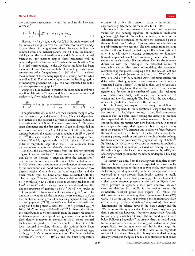
axis of the beam) and critical switching voltages for a number ofdoubly clamped graphene beams including SLG, BLG, andTLG (data included in Supporting Information). For thebeams, the expression analogous to eq 5 is
κελ μ
∝+
R Rd
Vn( 2 )
13
24
02
c4
(6)
The beam data has been plotted in Figure 5 in a plot oflog(Vc
4) versus log(R1−3), following eq 6. The data from the
BLG doubly clamped beams fall on a straight line in this plot.Assuming that the bending rigidity for the beams is identical tothat for the BLG fully clamped membranes, we can estimate thevalue of κ for the monolayer beams by comparing the values ofthe y-intercept on this plot. The comparison yields an estimateof κSLG = 7.1−3.0
+4.0 eV for the monolayer and κTLG = 126−53+71 eV for
the trilayer; however, it should be stressed that this is a veryrough estimate due to the limited number of data points usedto extract the values.By studying the voltage-induced snap-through of convex
buckled membranes and beams of suspended graphene, wehave shown that the mechanical behavior of BLG membranescan be described within continuum theory by treating them asconvex shells but we also show that care must be taken in thechoice of the parameters to be used and it is not alwaysappropriate to scale-down from the bulk values. The value thatwe obtain for the bending rigidity of BLG at room temperatureunder ambient conditions (35.5−15.0
+20.0 eV) is the first
Figure 4. Plot used to determine κ for fully clamped BLG. κ isdetermined from the value of the y- intercept at x = 0. Diamonds:average experimental values obtained from fitting the radii of curvaturefrom at least six AFM line scans on each substrate, error bars indicatethe standard deviation of the fitted radii. The full line is a straight-linefit to the data and the dashed lines indicate the stated error limits.
Nano Letters Letter
dx.doi.org/10.1021/nl301080v | Nano Lett. 2012, 12, 3526−35313530

experimental determination of this parameter for BLG. Thevalue lies in between the two extreme theoretical predictionsfor two completely independent monolayers at finite temper-ature and for bilayers at 0 K. An accurate experimentaldetermination of κ is crucial for understanding and correctlymodeling the mechanical behavior of this important newmaterial. The method that we present here is straightforwardand can easily be extended to thicker graphene layers or otherthin layer materials that can be fabricated to give similargeometries.
■ ASSOCIATED CONTENT*S Supporting InformationRaman studies of thermal cycling induced stress, residue teststudies, tabulated radii of curvature, and critical switchingvoltages. This material is available free of charge via the Internetat http://pubs.acs.org.
■ AUTHOR INFORMATIONCorresponding Author*E-mail: [email protected] Contributions#These authors contributed equally to the work.NotesThe authors declare no competing financial interest.
■ ACKNOWLEDGMENTSWe thank Jari Kinaret for useful technical discussions. Financialsupport from the Swedish Strategic Research Foundation (SSF)through “NEM arrayer for elektronik- och fotonikkomponent-er” (RE07-0004) is gratefully acknowledged. A.I. and D.M.acknowledge funding from the EU 7th Framework Program(FP7/2007-2013) under Grant 246026, RODIN. E.E.B.C.acknowledges financial support from the WCU program of theMEST (R31-2008-000-10057-0).
■ REFERENCES(1) Kudin, K. N.; Scuseria, G. E.; Yakobson, B. I.: C2F, BN and Cnanoshell elasticity from ab initio computations. Phys. Rev. B 2001, 64.(2) Cadelano, E.; Palla, P. L.; Giordano, S.; Colombo, L. NonlinearElasticity of Monolayer Graphene. Phys. Rev. Lett. 2009, 102, 235502.
(3) Atalaya, J.; Isacsson, A.; Kinaret, J. M. Continuum ElasticModelling of Graphene Resonators. Nano Lett. 2008, 8, 5.(4) Fasolino, A.; Los, J. H.; Katsnelson, M. I. Intrinsic ripples ingraphene. Nat. Mater. 2007, 6, 858−861.(5) Castro, E. V.; Ochoa, H.; Katsnelson, M. I.; Gorbachev, R. V.;Elias, D. C.; Novoselov, K. S.; Geim, A. K.; Guinea, F. Limits onCharge Carrier Mobility in Suspended Graphene due to FlexuralPhonons. Phys. Rev. Lett. 2010, 105, 266601.(6) Nicklow, R.; Wakabayashi, N.; Smith, H. G. Lattice Dynamics ofPyrolytic Graphite. Phys. Rev. B 1972, 5, 12.(7) Poot, M.; van der Zant, H. S. J. Nanomechanical properties offew-layer graphene membranes. Appl. Phys. Lett. 2008, 92, 063111.(8) Scharfenberg, S.; Rocklin, D. Z.; Chialvo, C.; Weaver, R. L.;Goldbart, P. M.; Mason, N. Probing the mechanical properties ofgraphene using a corrugated elastic substrate. Appl. Phys. Lett. 2011,98, 091908.(9) Zhang, D. B.; Akatyeva, E.; Dumitrica, T. Bending ultrathingraphene at the margins of continuum mechanics. Phys. Rev. Lett.2011, 106, 255503.(10) Lu, Q.; Arroyo, M.; Huang, R. Elastic bending modulus ofmonolayer graphene. J. Phys. D: Appl. Phys. 2009, 42, 102002.(11) Koskinen, P.; Kit, O. O. Approximate modeling of sphericalmembranes. Phys. Rev. B 2010, 82, 235420.(12) Zakharchenko, K. V.; Los, J. H.; Katsnelson, M. I.; Fasolino, A.Atomistic simulations of structural and thermodynamic properties ofbilayer graphene. Phys. Rev. B 2010, 81, 235439.(13) Lee, C.; Wei, X.; Kysar, J. W.; Hone, J. Measurement of theElastic Properties and Intrinsic Strength of Monolayer Graphene.Science 2008, 321, 385−388.(14) Garcia-Sanchez, D.; van der Zande, A. M.; Paulo, A. S.;Lassagne, B.; McEuen, P. L.; Bachtold, A. Imaging MechanicalVibrations in Suspended Graphene Sheets. Nano Lett. 2008, 8, 1399−1403.(15) Bunch, J. S.; van der Zande, A. M.; Verbridge, S. S.; Frank, I. W.;Tanenbaum, D. M.; Parpia, J. M.; Craighead, H. G.; McEuen, P. L.Electromechanical Resonators from Graphene Sheets. Science 2007,315, 490−493.(16) Bunch, J. S.; Verbridge, S. S.; Alden, J. S.; van der Zande, A. M.;Parpia, J. M.; Craighead, H. G.; McEuen, P. L. Impermeable AtomicMembranes from Graphene Sheets. Nano Lett. 2008, 8, 2458−2462.(17) Blakslee, O. L.; Proctor, D. G.; Seldin, E. J.; Spence, G. B.;Weng, T. Elastic constants of compression-annealed pyrolytic graphite.J. Appl. Phys. 1970, 41, 3373−3382.(18) Pogorelov, A. V. Bending of Surfaces and Stability of Shells, 1sted.; Amercan Mathematical Society: Providence, RI, 1988; Vol. 72.(19) Landau, L.; Lifschitz, E. Theory of Elasticity, 3rd ed.; Elsevier:New York, 1986; Vol. 7.(20) Novoselov, K. S.; Geim, A. K.; Morozov, S. V.; Jiang, D.; Zhang,Y.; Dubonos, S. V.; Grigorieva, I. V.; Firsov, A. A. Electric Field Effectin Atomically Thin Carbon Films. Science 2004, 306, 666−669.(21) Lefevre, R.; Goffman, M.; Derycke, V.; Miko, C.; Forro, L.;Bourgoin, J.; Hesto, P. Scaling Law in Carbon Nanotube Electro-mechanical Devices. Phys. Rev. Lett. 2005, 95, 185504.(22) Wong, C. L.; Annamalai, M.; Wang, Z. Q.; Palaniapan, M.Characterization of nanomechanical graphene drum structures. J.Micromech. Microeng. 2010, 20, 115029.(23) Svensson, J.; Lindahl, N.; Yun, H.; Seo, M.; Midtvedt, D.;Tarakanov, Y.; Lindvall, N.; Nerushev, O.; Kinaret, J.; Lee, S. W.;Campbell, E. E. B. Carbon Nanotube Field Effect Transistors withSuspended Graphene Gates. Nano Lett. 2011, 11, 3569−3575.
Figure 5. Data for doubly clamped beams showing the expected linearbehavior for a plot of log(Vc) versus log(R1
−3), see eqs 4 and 6. Filleddiamonds, doubly clamped BLG; open diamonds, SLG; open square,TLG. The full line is a least-squares fit to the BLG data yielding anintercept of 5.5. The dashed lines show the estimated fits for the SLG(intercept 4.8) and TLG (intercept 6.05) data. The bending rigiditycan be extracted by assuming that the bending rigidity of the doublyclamped BLG ribbons is identical to that of the fully clampedmembranes. This yields estimated values of κSLG = 7.1−3.0
+4.0 eV and κTLG= 126−53
+71 eV.
Nano Letters Letter
dx.doi.org/10.1021/nl301080v | Nano Lett. 2012, 12, 3526−35313531