Embed Size (px)
Citation preview

Determination of safe mud weight windows for drilling deviated wellbores: a case study in the North Perth Basin
K. Le & V. Rasouli Department of Petroleum Engineering, Curtin University, Australia
Abstract
Drilling non-vertical wells, which is commonly used to enhance production, in particular in unconventional reservoirs with very low permeability, is subjected to rock mechanics related issues namely wellbore instabilities. Drilling in the same formation but with different deviations and at different directions would not result in similar response in terms of rock failures. This is due to the rotation of the induced stresses around the wellbore wall along its trajectory. The type of instabilities that the formation experiences around the wellbore is a function of formation’s mechanical properties and the status of in-situ stresses. It is clear that none of these natural parameters can be controlled or changed during drilling operation. However, the density of the mud weigh which is used to drill the wellbore could be optimised in order to mitigate or stop wellbore instability issues in the form of tensile failure or fracturing in case of using high mud density or shear failure or breakouts when a low mud weigh is used. Therefore, a safe mud weight window (MWW) can be determined for optimum drilling in terms of having the least issues related to wellbore instabilities. This MWW will change as the wellbore deviation changes. In this paper, the concept of constructing the rock mechanical model (RMM) which includes the rock mechanical properties as well as in-situ stress profiles is briefly presented. Then the RMM output corresponding to vertical well Arrowsmith-1 which is a shale gas well drilled in the North Perth Basin of Australia will be used to calculate the safe MWW for drilling wellbores in different azimuth and deviation in the field. The results indicate how the MWW changes as a function of wellbore trajectory. Keywords: wellbore instability, mud weight windows, breakouts, fracturing, in-situ stresses Arrowsmith-1.
Petroleum and Mineral Resources 83
www.witpress.com, ISSN 1743-3533 (on-line) WIT Transactions on Engineering Sciences, Vol 81, © 201 WIT Press2
doi:10.2495/PMR120081

1 Introduction
Drilling deep wellbores in oil and gas industry is to access the reservoir formation for production purposes. While drilling vertical wells is a common approach, sometimes it is necessary to drill deviated or horizontal wells. This, for example, helps in more production as it provides larger exposure to the formation, so the hydrocarbon can more easily being produced. Drilling non-vertical wells is more important in unconventional reservoirs such as gas shales or tight formations as the hydrocarbon bearing formations in such reservoirs exhibit very low permeability and having large exposure to the wellbore wall is essential for economical production rate (Joshi [2]) Part of the issues related to drilling deviated wellbores is related to the type of formation failures observed during drilling. It is the formation’s mechanical properties together with the state of stresses induced around the wellbore which defines the potential of failures of the rocks around the wellbore wall. However, as the wellbore direction and deviation changes, while the formation is the same the effect of transformed stresses around the wellbore wall will be different. This is obvious that neither rock properties nor in-situ stresses can be changed to mitigate the failures of the wellbore. However, the density of the drilling mud can significantly control the situation. Large wellbore pressure, due to using high mud density could enforce the formation to open in tensile mode, which in due course may result in mud loss or ultimately fracturing the formation. Also, using a low density mud, corresponding to low wellbore pressure may result in rock failure in shear mode and consequently breakouts. Very low mud weight of below the reservoir pressure will result in a kick (Nas [1]). Therefore there is a safe mud weight window (MWW) to be used for drilling with minimum instability issues. In order to perform a complete wellbore stability analysis considering a given mud weight used for drilling, as explained above, we need two sets of information: the formation mechanical properties (i.e. Young’s modulus, Poisson’s ratio, compression and tensile strength) and the state of in-situ stresses (i.e. magnitude of vertical and maximum and minimum horizontal stresses) and the direction of maximum stress, plus the magnitude of pore pressure (Rasouli
mechanical modelling (RMM). Understanding that there is relationship between rock’s physical properties (e.g. porosity) which is captured by petrophysical logs and its mechanical properties, the RMM builds continuous profiles of rock elastic and mechanical properties as well as stresses (Rasouli et al. [3] and Archer and Rasouli [4]). The output of the RMM is used for various studies including determination of the MWW, design of a hydraulic fracturing job and sanding analysis. The results of the RMM for a vertical well could be used to estimate the safe MWW if drilling deviated wells in different directions. In this paper a brief review of the RMM will be given in the following section with an introduction to various failures that are expected around the wellbore with respect to the mud weight used for drilling. Then the RMM output from
et al. [3]). Th s information could be obtained through a process called rock i
84 Petroleum and Mineral Resources
www.witpress.com, ISSN 1743-3533 (on-line) WIT Transactions on Engineering Sciences, Vol 81, © 201 WIT Press2

another study [4] carried out in Arrowsmith 1 well, a gas shale well drilled vertically in the North Perth Basin of Australia, will be used to estimate the safe MWW corresponding to deviated wellbores drilled in different directions. Here the calculations are performed in two specific depths but similar analysis can be performed at any other depth.
2 The concept of RMM and MWW determination
The RMM or mechanical earth model (MEM) is the process of extracting continuous profiles of mechanical properties of the formations and the in-situ stresses. The model is built based on the petrophysical logs with an understanding that these logs carry various physical properties of the formations such as porosity or sound velocity and these can be indicators for mechanical properties and the magnitude of stresses in the field. For example, large sonic velocity obtained from sonic logs would be an indication of less porosity or larger density which in turn shows a stiffer and stronger formation with less Poisson’s ratio. Using available formulae it is possible to calculate the dynamic elastic properties and then change them into static properties through the use of correlations proposed for different fields. The mechanical properties, mainly the rock uniaxial compressive strength can be estimated using correlations proposed by different people in relation to different elastic and physical properties. The obtained logs can be calibrated against laboratory test data of some samples from the field. The magnitude of vertical stress can be obtained by integrating the density of the rocks. The maximum and minimum horizontal stresses which are functions of the vertical stress and elastic properties will be calculated through the poro-elastic formulae. The detailed process of constructing a RMM can be found in Rasouli et al. [3] and Archer and Rasouli [4]. Figure 1 shows an example output of the RMM built for a vertical well Archer and Rasouli [4]. The model corresponds to well Arrowsmith-1 in the North Perth Basin of Australia, This is a gas shale well which was drilled to study the potential of gas production form underlying formations. The first track in Figure 1 is the depth and the formation tops are shown in track 2. Track 3 shows the dynamic and static Young’s moduli of the formations. The fourth track is the static bulk and shear moduli with the fifth tack presenting the Poisson’s ratio and the Biot’s poro-elastic coefficient, which is considered 1 in this figure. Track 6 represents the uniaxial compressive strength (UCS), tensile strength and friction angle of formations. These tracks constitute the formation’s mechanical properties (elastic and strengths). In track 7 the extracted pore pressure, vertical stress and two horizontal stresses are shown. From this track it is seen that the stress regime above depth of approximately 2500m, i.e. in Kockatea shale and above formations is dominantly strike-slip regime and the order of stress magnitudes is Hmax>V>Hmin
. However, moving down the stress regime tends to become dominantly a normal stress regime (i.e. V>Hmax>Hmin). It will be discussed in section 4 that this change in stress
Petroleum and Mineral Resources 85
www.witpress.com, ISSN 1743-3533 (on-line) WIT Transactions on Engineering Sciences, Vol 81, © 201 WIT Press2
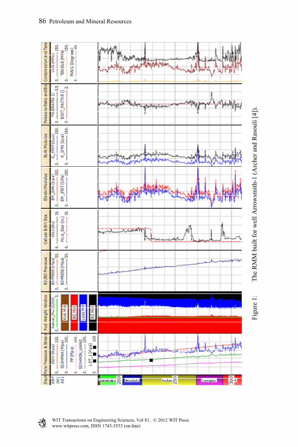
Fig
ure
1:
The
RM
M b
uilt
for
wel
l Arr
owsm
ith-
1 (A
rche
r an
d R
asou
li [
4]).
86 Petroleum and Mineral Resources
www.witpress.com, ISSN 1743-3533 (on-line) WIT Transactions on Engineering Sciences, Vol 81, © 201 WIT Press2
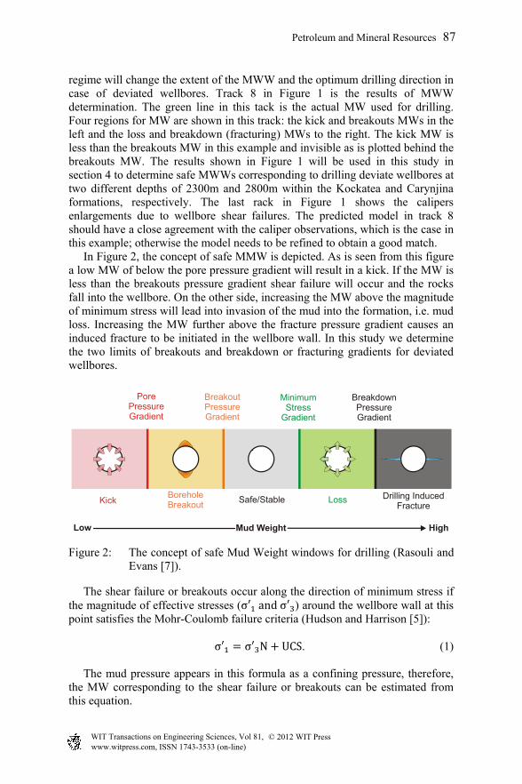
regime will change the extent of the MWW and the optimum drilling direction in case of deviated wellbores. Track 8 in Figure 1 is the results of MWW determination. The green line in this tack is the actual MW used for drilling. Four regions for MW are shown in this track: the kick and breakouts MWs in the left and the loss and breakdown (fracturing) MWs to the right. The kick MW is less than the breakouts MW in this example and invisible as is plotted behind the breakouts MW. The results shown in Figure 1 will be used in this study in section 4 to determine safe MWWs corresponding to drilling deviate wellbores at two different depths of 2300m and 2800m within the Kockatea and Carynjina formations, respectively. The last rack in Figure 1 shows the calipers enlargements due to wellbore shear failures. The predicted model in track 8 should have a close agreement with the caliper observations, which is the case in this example; otherwise the model needs to be refined to obtain a good match. In Figure 2, the concept of safe MMW is depicted. As is seen from this figure a low MW of below the pore pressure gradient will result in a kick. If the MW is less than the breakouts pressure gradient shear failure will occur and the rocks fall into the wellbore. On the other side, increasing the MW above the magnitude of minimum stress will lead into invasion of the mud into the formation, i.e. mud loss. Increasing the MW further above the fracture pressure gradient causes an induced fracture to be initiated in the wellbore wall. In this study we determine the two limits of breakouts and breakdown or fracturing gradients for deviated wellbores.
Figure 2: The concept of safe Mud Weight windows for drilling (Rasouli and Evans [7]).
The shear failure or breakouts occur along the direction of minimum stress if the magnitude of effective stresses (σ and σ ) around the wellbore wall at this point satisfies the Mohr-Coulomb failure criteria (Hudson and Harrison [5]): σ σ N UCS . (1) The mud pressure appears in this formula as a confining pressure, therefore, the MW corresponding to the shear failure or breakouts can be estimated from this equation.
Pore Pressure Gradient
Breakout Pressure Gradient
Minimum Stress
Gradient
Breakdown Pressure Gradient
KickBorehole Breakout
Loss Drilling Induced Fracture
Safe/Stable
Mud Weight HighLow
Petroleum and Mineral Resources 87
www.witpress.com, ISSN 1743-3533 (on-line) WIT Transactions on Engineering Sciences, Vol 81, © 201 WIT Press2

The induced fracture initiates from the wellbore wall along the maximum stress direction, i.e. perpendicular to the minimum resistance stress, when the wellbore pressure (Pw) exceeds the minimum hoop stresses around the wellbore plus the formation tensile strength (T) (Fjaer et al. [6]): σ T Pw (2) This in turn can be simplified for calculation purposes as: σ T (3)
3 Calculations of MWW in non-vertical wellbores
As stated in the previous sections, when the wellbore trajectory changes from being vertical, the stress concentration around the wellbore wall changes. While the stresses were principal stresses in the first instance, now around the deviated trajectory they are no longer principal stresses and therefore shear stress exist. This means that the in-situ stresses must first be transferred to a Cartesian coordinate system comprising of normal stresses and shear stresses in the direction of the deviated wellbore. These stresses can be calculated from the following equations (Fjaer et al. [6]):
° (4)
° (5)
° (6)
° (7)
° (8)
° (9)
Here the normal stress transformation equations consider principal vertical and horizontal stresses (v, H, h) unlike the shear stress transformation equations which consider the effective counterparts of the vertical and horizontal stresses. In the above equations the transformation coefficients (cosine directions) can be calculated from the wellbore azimuth direction angle (a) and inclination (i) as below:
cos cos , sin cos , sin (10)sin , cos , 0 (11)
cos sin , sin sin , cos (12)
88 Petroleum and Mineral Resources
www.witpress.com, ISSN 1743-3533 (on-line) WIT Transactions on Engineering Sciences, Vol 81, © 201 WIT Press2
Once the normal and shear stresses have been determined then they must be converted into cylindrical coordinates which take into account their respective positions around the wellbore (i.e. angle ) at that specific azimuth and inclination. These equations are in represented as below (Fjaer et al. [6]):
(13)° ° 2 ° ° 2 4 ° 2 (14)
° 2 ° ° 2 4 ° 2 (15)
0 (16)2 ° ° (17)
0 (18) As explained before, and is seen from equation (24), at least one of the shear stresses is non-zero, which means that these stresses are not principal stresses. Therefore, in order to do calculations of MWW for both breakouts (i.e. shear failure) and breakdown (i.e. tensile failure) these stresses should be transferred into principal stresses. The following equations apply Mohr Coulomb principles and account for the normal and shear stresses to provide equations for the three principal stresses:
(19) 12
4 (20)
12
4 (21)
These principal stresses calculated around the deviated trajectory will be used to determine the safe MWW for both breakouts and fracturing through equations (1) and (2).
4 Case study
In this section, we use the RMM results for well Arrowsmith-1 (see Figure 1) to calculate the safe MWW, using equations presented in the previous section, for deviated wellbores drilled in different directions. In this study we carry out the analysis for two different depths of 2300m and 2800m in Kockatea and Carynjinia formations, respectively, as examples to present the results and corresponding interpretation. Similar analysis can be done for other depths. From Figure 1, the extracted data corresponding to the two depths are listed in Table 1. From Table 1 it is seen that the stress regime at the depth of 2300m is strike-slip, as the magnitude of maximum horizontal stress is the largest among the three principal stresses, whereas at 2800m the stress regime is normal as vertical
Petroleum and Mineral Resources 89
www.witpress.com, ISSN 1743-3533 (on-line) WIT Transactions on Engineering Sciences, Vol 81, © 201 WIT Press2
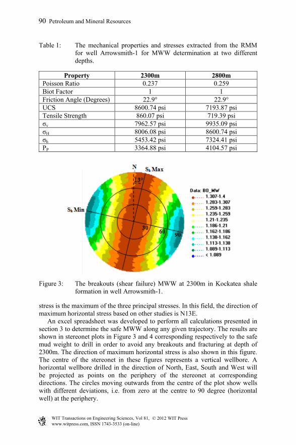
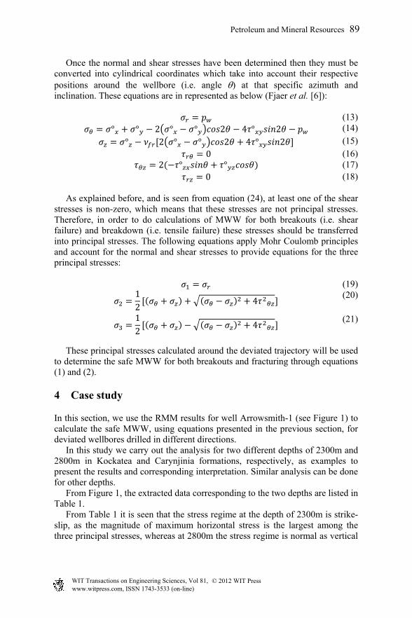
Table 1: The mechanical properties and stresses extracted from the RMM for well Arrowsmith-1 for MWW determination at two different depths.
Property 2300m 2800m Poisson Ratio 0.237 0.259 Biot Factor 1 1 Friction Angle (Degrees) 22.9° 22.9° UCS 8600.74 psi 7193.87 psi Tensile Strength 860.07 psi 719.39 psi σv 7962.57 psi 9935.09 psi σH 8006.08 psi 8600.74 psi σh 5453.42 psi 7324.41 psi PP 3364.88 psi 4104.57 psi
Figure 3: The breakouts (shear failure) MWW at 2300m in Kockatea shale formation in well Arrowsmith-1.
stress is the maximum of the three principal stresses. In this field, the direction of maximum horizontal stress based on other studies is N13E. An excel spreadsheet was developed to perform all calculations presented in section 3 to determine the safe MWW along any given trajectory. The results are shown in stereonet plots in Figure 3 and 4 corresponding respectively to the safe mud weight to drill in order to avoid any breakouts and fracturing at depth of 2300m. The direction of maximum horizontal stress is also shown in this figure. The centre of the stereonet in these figures represents a vertical wellbore. A horizontal wellbore drilled in the direction of North, East, South and West will be projected as points on the periphery of the stereonet at corresponding directions. The circles moving outwards from the centre of the plot show wells with different deviations, i.e. from zero at the centre to 90 degree (horizontal well) at the periphery.
90 Petroleum and Mineral Resources
www.witpress.com, ISSN 1743-3533 (on-line) WIT Transactions on Engineering Sciences, Vol 81, © 201 WIT Press2

Figure 4: The breakdown (tensile failure) MWW at 2300m in Kockatea shale formation in well Arrowsmith-1.
As an example, based on the results of Figures 3 and 4 it is seen that at depth of 2300m in Kockatea shale a vertical well is drilled safely if the MW is within the range of 1.34 SG and 1.79 SG. This, in fact, is the results obtained from Figure 1. As another example, to drill a deviated wellbore with an angle of 30 degrees from vertical requires the use of a MW with a density of between 1.33 SG and 1.79 SG if drilling in the direction of maximum horizontal stress.
Figure 5: Mohr Circles showing least instability in the direction of minimum horizontal stress.
Depending on the difference between the three principal stresses around the wellbore, the optimal direction to drill can be either along maximum or minimum horizontal stress according to the Mohr Coulomb Circles principle seen in Figure 5 which shows the Mohr Circles following the stresses at 2300m. As is seen from Figures 3 and 4, the best direction to drill at this depth in terms of encountering least instability problems is along the direction of
Petroleum and Mineral Resources 91
www.witpress.com, ISSN 1743-3533 (on-line) WIT Transactions on Engineering Sciences, Vol 81, © 201 WIT Press2
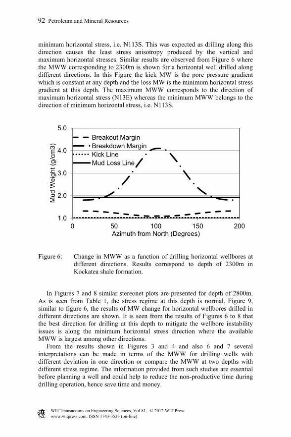
minimum horizontal stress, i.e. N113S. This was expected as drilling along this direction causes the least stress anisotropy produced by the vertical and maximum horizontal stresses. Similar results are observed from Figure 6 where the MWW corresponding to 2300m is shown for a horizontal well drilled along different directions. In this Figure the kick MW is the pore pressure gradient which is constant at any depth and the loss MW is the minimum horizontal stress gradient at this depth. The maximum MWW corresponds to the direction of maximum horizontal stress (N13E) whereas the minimum MWW belongs to the direction of minimum horizontal stress, i.e. N113S.
Figure 6: Change in MWW as a function of drilling horizontal wellbores at different directions. Results correspond to depth of 2300m in Kockatea shale formation.
In Figures 7 and 8 similar stereonet plots are presented for depth of 2800m. As is seen from Table 1, the stress regime at this depth is normal. Figure 9, similar to figure 6, the results of MW change for horizontal wellbores drilled in different directions are shown. It is seen from the results of Figures 6 to 8 that the best direction for drilling at this depth to mitigate the wellbore instability issues is along the minimum horizontal stress direction where the available MWW is largest among other directions. From the results shown in Figures 3 and 4 and also 6 and 7 several interpretations can be made in terms of the MWW for drilling wells with different deviation in one direction or compare the MWW at two depths with different stress regime. The information provided from such studies are essential before planning a well and could help to reduce the non-productive time during drilling operation, hence save time and money.
1.0
2.0
3.0
4.0
5.0
0 50 100 150 200
Mud
Wei
ght (
g/cm
3)
Azimuth from North (Degrees)
Breakout MarginBreakdown MarginKick LineMud Loss Line
92 Petroleum and Mineral Resources
www.witpress.com, ISSN 1743-3533 (on-line) WIT Transactions on Engineering Sciences, Vol 81, © 201 WIT Press2
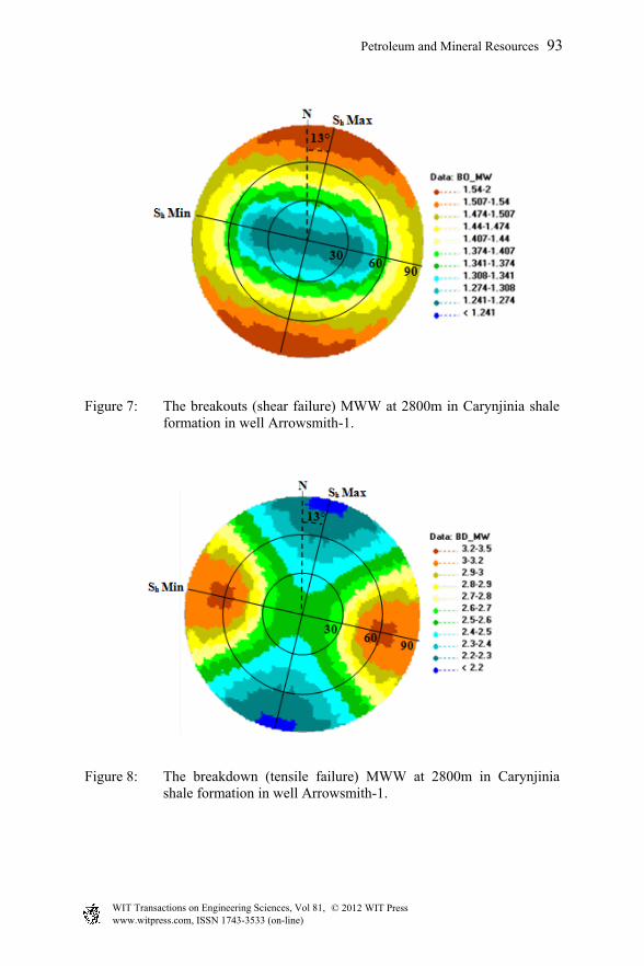
Figure 7: The breakouts (shear failure) MWW at 2800m in Carynjinia shale formation in well Arrowsmith-1.
Figure 8: The breakdown (tensile failure) MWW at 2800m in Carynjinia shale formation in well Arrowsmith-1.
Petroleum and Mineral Resources 93
www.witpress.com, ISSN 1743-3533 (on-line) WIT Transactions on Engineering Sciences, Vol 81, © 201 WIT Press2

Figure 9: Change in MWW as a function of drilling horizontal wellbores at different directions. Results correspond to depth of 2800m in Kockatea shale formation.
5 Conclusion
In this study it was discussed how changing the wellbore trajectory could result in different wellbore instability issues and therefore it is important to determine the safe MWW for drilling in any given azimuth and deviation. The rock mechanical model (RMM) was introduced to extract the mechanical properties of the formations and estimate the state of in-situ stresses in a field based on petrophysical data collected from one or several wells. The mathematical calculations presented to determine the MWW for a given trajectory was applied to Arrowsmith-1 vertical well, which is a gas shale well drilled in the North Perth Basin. The results presented for two different depths of 2300m within Kockatea shale and 2800m within Carynjinia shale formations. The stress regime at the first depth was strike-slip, whereas at the second depth was normal. The results presented on stereonet plot allow determining the safe MWW for drilling along any trajectory. In particular it was observed that at 2300m, the best direction to drill in order to minimise the impact of wellbore instability issues was in fact the minimum stress direction. The minimum stress direction was also found to be the best direction to drill at 2800m where the stress regime is normal.
References
[1] Nas, S., Kick detection and well control in a closed wellbore, IADC/SPE Managed Pressure Drilling and Underbalance Operations Conference and Exhibition, pp. 3, 5-6 April 2011.
[2] Joshi, S.D., Cost/benefits of horizontal wells, SPE Western Regional/AAPG Pacific Section Joint Meeting, pp. 1, 19-24 May 2003.
1.0
2.0
3.0
4.0
0 50 100 150 200
Mud
Wei
ght (
g/cm
3)
Azimuth from North (Degrees)
Breakout MarginBreakdown MarginKick LineMud Loss Line
94 Petroleum and Mineral Resources
www.witpress.com, ISSN 1743-3533 (on-line) WIT Transactions on Engineering Sciences, Vol 81, © 201 WIT Press2

[3] Rasouli, V., Zacharia, J., and Elike, Optimum well trajectory design in a planned well in Blacktip field, Australia, APPEA journal,50, 535-548, 2010.
[4] Archer, S., and Rasouli, V., A log based analysis to estimate mechanical properties and in-situ stresses in a shale gas well in North Perth Basin, 1st International Conference on Petroleum and Mineral Resources, 4 - 6 December, Koya, Kurdistan, Iraq, 2012.
[5] Hudson, J.A. and Harrison, J.P., Engineering rock mechanics. An introduction to the principles Volume 1 (Chapter 6). Intct rock, Elsevier Science: Pergamon, pp. 107-108, 1997.
[6] Fjaer, E., Holt, R.M., Horsrud, P., Raaen, A.M., and Risnes, R., Petroleum related rock mechanics 2nd edition (Chapter 4). Stresses around boreholes. Borehole failure criteria, Elsevier: Amsterdam, pp. 59, 146-148, 2008.
[7] Rasouli, V., Evans, B. J., Maximised production through deviated drilling and fraccing. Petroleum exploration society of Australia (PESA) resources. Issue No. 103, December/January 2009/2010. ISSN 1039-4419. pp. 62-64, 2010.
Petroleum and Mineral Resources 95
www.witpress.com, ISSN 1743-3533 (on-line) WIT Transactions on Engineering Sciences, Vol 81, © 201 WIT Press2