Embed Size (px)
Citation preview
Saxena and Khazanovich 1
TRB 12-2198 1
DETERMINATION OF CRITICAL BENDING STRESSES IN THE PCC LAYER WITH 2
ASPHALT OVERLAY 3 4
5
Priyam Saxena, Ph.D
University of Minnesota
Department of Civil Engineering
500 Pillsbury Drive S.E.
Minneapolis, MN 55455
E-mail: [email protected]
Lev Khazanovich, Ph.D
Associate Professor
University of Minnesota
Department of Civil Engineering
500 Pillsbury Drive S.E.
Minneapolis, MN 55455
E-mail: [email protected]
6
7
8
9
Paper submitted November 15, 2011 in consideration for the 10
Transportation Research Board 91st Annual Meeting, 11
22-26 January 2012 12
13
14
Words: 5182 15
Figures: 6 16
Tables: 3 17
Total Word Count: 7432 18
19
TRB 2012 Annual Meeting Paper revised from original submittal.
Saxena and Khazanovich 2
DETERMINATION OF CRITICAL BENDING STRESSES IN THE PCC LAYER WITH 1
ASPHALT OVERLAY 2 3
4
ABSTRACT 5 6
An asphalt concrete (AC) overlay of a jointed plain concrete pavement (JPCP) is intended to 7
extend the service life of the existing pavement structure. Also known as composite pavements, 8
these pavements exhibit features of both rigid and flexible pavements. While behavior of rigid 9
pavements is mainly elastic, behavior of an asphalt layer is load-duration dependent. At the 10
same time, temperature curling causes non-linear interaction with the foundation. The available 11
structural models for composite pavements ignore the behavior of the load duration dependent 12
asphalt layer when the composite pavement is subjected to a combination of temperature curling 13
and traffic loads. This research concentrates on the improvement of structural modeling of 14
composite pavements that are subjected to slow developing temperature curling and 15
instantaneous traffic loads. In order to maintain compatibility with the Mechanistic-Empirical 16
Pavement Design Guide (MEPDG) framework, a simplified procedure is developed. This 17
procedure uses a different asphalt modulus for curling than for axle loading; and determines the 18
total stresses in the pavement as a combination of the stresses from solutions of three elastic 19
boundary value problems. The simplified procedure is compared with the existing MEPDG 20
structural model for fatigue cracking in AC overlaid JPCP. A framework for implementing the 21
proposed procedure into the MEPDG is also developed. 22
23
INTRODUCTION 24 25
Asphalt concrete (AC) overlays are used routinely to rehabilitate existing jointed plain concrete 26
pavements (JPCP). However, many asphalt overlays fail prematurely due to transverse cracking 27
in the portland cement concrete (PCC) layer reflecting through the asphalt. The Mechanistic 28
Empirical Pavement Design Guide (MEPDG) identifies transverse cracking in the PCC layer as a 29
major distress that is important to control. 30
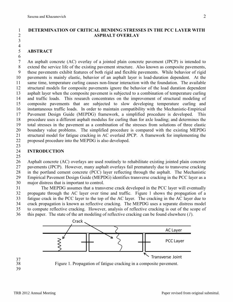
The MEPDG assumes that a transverse crack developed in the PCC layer will eventually 31
propagate through the AC layer over time and traffic. Figure 1 shows the propagation of a 32
fatigue crack in the PCC layer to the top of the AC layer. The cracking in the AC layer due to 33
crack propagation is known as reflective cracking. The MEPDG uses a separate distress model 34
to compute reflective cracking. However, analysis of reflective cracking is out of the scope of 35
this paper. The state of the art modeling of reflective cracking can be found elsewhere (1). 36
37 Figure 1. Propagation of fatigue cracking in a composite pavement. 38
39
AC Layer
PCC Layer
Crack
Transverse Joint
TRB 2012 Annual Meeting Paper revised from original submittal.
Saxena and Khazanovich 3
The MEPDG distress model for predicting transverse cracking in the PCC layer of an AC 1
overlaid JPCP (referred herein as a composite pavement) was adopted directly from the fatigue 2
cracking model of a new jointed plain concrete pavement (2). The model has the following 3
form: 4
5
( ) %100⋅⋅−+= −−−− downTopupBottomdownTopupBottom CRKCRKCRKCRKTCRACK (1) 6
68.11
100−+
=FD
CRK (2) 7
∑=pmlkjt
pmlkjt
N
nFD
,,,,,
,,,,,
(3) 8
(4) 9
10
where 11
TCRACK is the total transverse cracking (percent, all severities), 12
CRK is the percentage of bottom-up or top-down PCC cracking, 13
FD is the fatigue damage, 14
n is the applied number of load applications at conditions t, j, k, l, m, p, 15
N is the allowable number of load applications at conditions t, j, k, l, m, p, 16
t, j, k, l, m, p are conditions relating to the age, month, axle type, load level, temperature 17
difference, and traffic path, respectively, 18
MR is the modulus of rupture of PCC, 19
σ is the applied stress at conditions t, j, k, l, m, p, and 20
C1, C2 are calibration constants (C1 = 2.0, C2 = 1.22). 21
22
Equation (4) implies that cracking in the PCC layer is a function of the “applied stress” and thus 23
depends on the various factors related to traffic loads and temperature gradients. Accurate 24
computation of the stress at the critical location in the PCC layer is an important step in the 25
calculation of fatigue cracking. 26
To compute structural responses such as stresses, strains, and displacements, constitutive 27
relationships for each layer in the structural model should be provided. Asphalt is a viscoelastic 28
material; its structural responses depend not only on the magnitude of the applied load but on the 29
load duration as well. However, conducting a viscoelastic analysis for each combination of site 30
and loading conditions required by the MEPDG damage computation process would be 31
computationally prohibitive. In order to simplify the structural analysis, the MEPDG treats 32
asphalt layers as elastic, but to account for the viscoelastic behavior of the asphalt layer, the 33
MEPDG assumes that the asphalt modulus of elasticity is equal to the load duration-dependent 34
dynamic (complex) modulus. 35
The loading duration for traffic loads depends on the vehicle speed. If vehicle speed is 36
approximately 60 mph, then the loading duration ranges between 0.01 sec and 0.05 seconds. 37
However, the duration of temperature loading is significantly longer. The MEPDG analysis of 38
flexible pavements ignores temperature-induced asphalt stresses and strains for all the distress 39
models except the low-temperature cracking model. In the low-temperature cracking model, the 40
..)log(
2
,,,,,
1 ,,,,,
=
C
p m l k j t p m l k j t
MR C N
σ
TRB 2012 Annual Meeting Paper revised from original submittal.
Saxena and Khazanovich 4
temperature-induced stresses are accounted for but asphalt material is characterized differently 1
and the axle load-induced stresses are ignored. Therefore, the MEPDG framework used to 2
account for the viscoelastic behavior of asphalt layers in the design of flexible pavements can be 3
considered reasonable. 4
The situation is quite different in the case of asphalt overlays of concrete pavements 5
because the MEPDG implicitly accounts for both traffic and temperature induced stresses and 6
strains in the asphalt layer. The MEPDG recognizes that there is an interaction between 7
temperature curling and deformations due to traffic loading for the JPCP and AC overlays of 8
JPCP. Temperature gradients and traffic loads both cause bending stresses in the concrete layer 9
that cannot be simply added when asphalt overlaid concrete pavements are subjected to a 10
combination of temperature gradients and instantaneous traffic loads. This is because 11
temperature curling causes a separation of the slab from the subgrade, causing the system to 12
behave non-linearly. Moreover, the loading durations of temperature gradients and fast moving 13
traffic loads are significantly different. Therefore, for the case of asphalt overlays of JPCP in the 14
MEPDG framework, the characterization of the AC layer using a single dynamic modulus may 15
be an over-simplification. 16
The objective of this study is to verify whether the use of a single dynamic modulus to 17
characterize the AC layer (in the case of composite pavements only) is a valid assumption in the 18
adoption of the JPCP fatigue cracking structural model when the composite pavement is 19
subjected to a combination of temperature gradients and traffic loads. Secondly, a procedure 20
named 2-moduli approach is developed such that two different AC moduli, corresponding to the 21
different loading durations of temperature loads and traffic loads, are used to represent the AC 22
layer. The combined stress in the composite pavement, subjected to temperature gradients and 23
traffic loads, is computed and a framework is developed to allow for the implementation of this 24
procedure in the existing framework of the MEPDG methodology. 25
26
AC MODULUS UNDER TRAFFIC LOADS AND TEMPERATURE GRADIENTS 27 28
The MEPDG characterizes the viscoelastic behavior of the AC layer using a load duration-29
dependent dynamic modulus. The dynamic modulus of asphalt is computed using a master curve 30
of sigmoidal shape (3), at a reference temperature of 70°F, as shown by the following equations: 31
32
)logexp1log
)(tγ(β
αδ)(E
r
AC +++=
(5) 33
34
where 35
EAC is the dynamic modulus of asphalt, 36
δ, α, β, and γ are parameters based on the volumetric property of the asphalt mix, and 37
tr is the reduced time. 38
39
The reduced time accounts for the effects of temperature and the rate of loading. It is given as: 40
41
( ))log()log(*)log()log( TRr ctt ηη −−= (6) 42
43
where 44
TRB 2012 Annual Meeting Paper revised from original submittal.
Saxena and Khazanovich 5
t is the actual loading time, 1
c = 1.255882, and 2
η, ηTR are viscosities at temperature T and reference temperature TR, respectively. 3
4
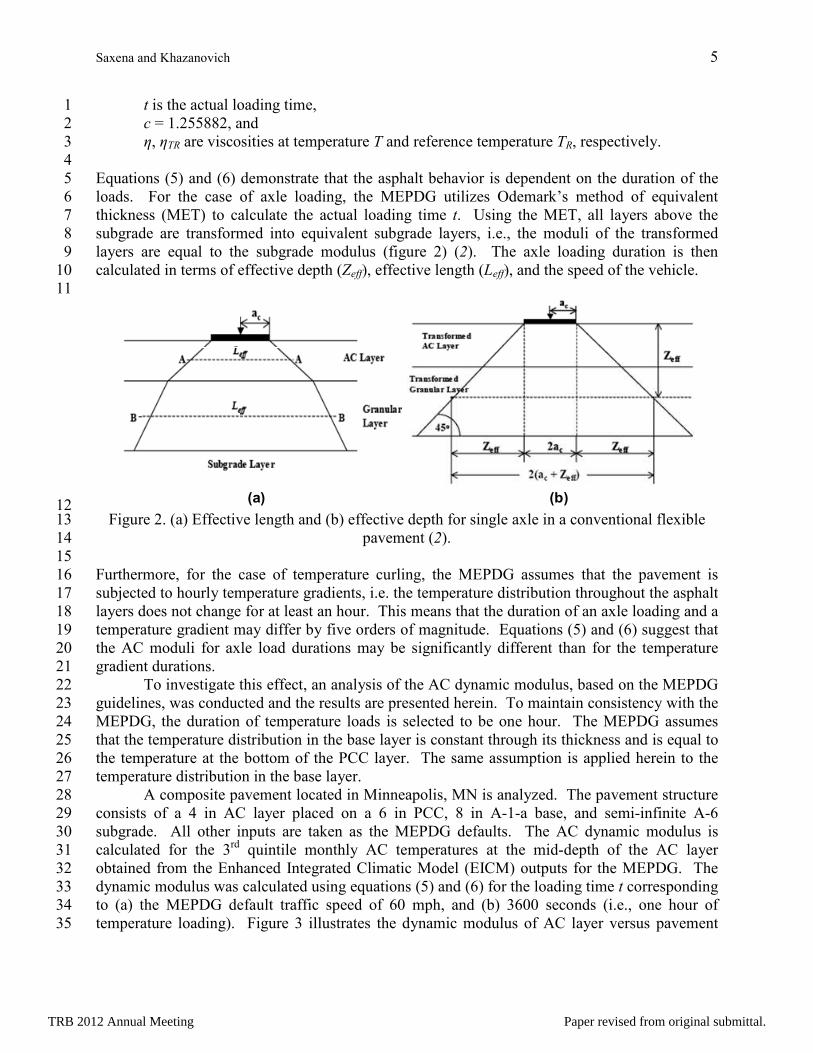
Equations (5) and (6) demonstrate that the asphalt behavior is dependent on the duration of the 5
loads. For the case of axle loading, the MEPDG utilizes Odemark’s method of equivalent 6
thickness (MET) to calculate the actual loading time t. Using the MET, all layers above the 7
subgrade are transformed into equivalent subgrade layers, i.e., the moduli of the transformed 8
layers are equal to the subgrade modulus (figure 2) (2). The axle loading duration is then 9
calculated in terms of effective depth (Zeff), effective length (Leff), and the speed of the vehicle. 10
11
12 Figure 2. (a) Effective length and (b) effective depth for single axle in a conventional flexible 13
pavement (2). 14
15
Furthermore, for the case of temperature curling, the MEPDG assumes that the pavement is 16
subjected to hourly temperature gradients, i.e. the temperature distribution throughout the asphalt 17
layers does not change for at least an hour. This means that the duration of an axle loading and a 18
temperature gradient may differ by five orders of magnitude. Equations (5) and (6) suggest that 19
the AC moduli for axle load durations may be significantly different than for the temperature 20
gradient durations. 21
To investigate this effect, an analysis of the AC dynamic modulus, based on the MEPDG 22
guidelines, was conducted and the results are presented herein. To maintain consistency with the 23
MEPDG, the duration of temperature loads is selected to be one hour. The MEPDG assumes 24
that the temperature distribution in the base layer is constant through its thickness and is equal to 25
the temperature at the bottom of the PCC layer. The same assumption is applied herein to the 26
temperature distribution in the base layer. 27
A composite pavement located in Minneapolis, MN is analyzed. The pavement structure 28
consists of a 4 in AC layer placed on a 6 in PCC, 8 in A-1-a base, and semi-infinite A-6 29
subgrade. All other inputs are taken as the MEPDG defaults. The AC dynamic modulus is 30
calculated for the 3rd
quintile monthly AC temperatures at the mid-depth of the AC layer 31
obtained from the Enhanced Integrated Climatic Model (EICM) outputs for the MEPDG. The 32
dynamic modulus was calculated using equations (5) and (6) for the loading time t corresponding 33
to (a) the MEPDG default traffic speed of 60 mph, and (b) 3600 seconds (i.e., one hour of 34
temperature loading). Figure 3 illustrates the dynamic modulus of AC layer versus pavement 35
(a) (b)
TRB 2012 Annual Meeting Paper revised from original submittal.
Saxena and Khazanovich 6
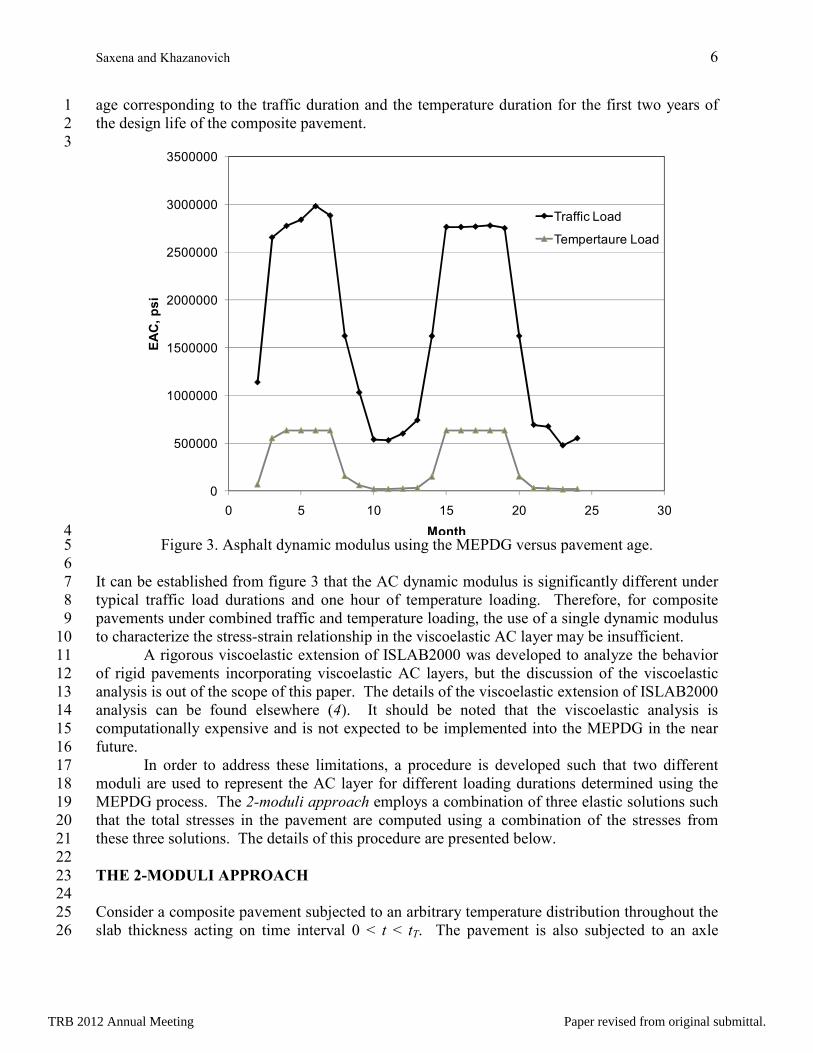
age corresponding to the traffic duration and the temperature duration for the first two years of 1
the design life of the composite pavement. 2
3
4 Figure 3. Asphalt dynamic modulus using the MEPDG versus pavement age. 5
6
It can be established from figure 3 that the AC dynamic modulus is significantly different under 7
typical traffic load durations and one hour of temperature loading. Therefore, for composite 8
pavements under combined traffic and temperature loading, the use of a single dynamic modulus 9
to characterize the stress-strain relationship in the viscoelastic AC layer may be insufficient. 10
A rigorous viscoelastic extension of ISLAB2000 was developed to analyze the behavior 11
of rigid pavements incorporating viscoelastic AC layers, but the discussion of the viscoelastic 12
analysis is out of the scope of this paper. The details of the viscoelastic extension of ISLAB2000 13
analysis can be found elsewhere (4). It should be noted that the viscoelastic analysis is 14
computationally expensive and is not expected to be implemented into the MEPDG in the near 15
future. 16
In order to address these limitations, a procedure is developed such that two different 17
moduli are used to represent the AC layer for different loading durations determined using the 18
MEPDG process. The 2-moduli approach employs a combination of three elastic solutions such 19
that the total stresses in the pavement are computed using a combination of the stresses from 20
these three solutions. The details of this procedure are presented below. 21
22
THE 2-MODULI APPROACH 23 24
Consider a composite pavement subjected to an arbitrary temperature distribution throughout the 25
slab thickness acting on time interval 0 < t < tT. The pavement is also subjected to an axle 26
0
500000
1000000
1500000
2000000
2500000
3000000
3500000
0 5 10 15 20 25 30
EAC, psi
Month
Traffic Load
Tempertaure Load
TRB 2012 Annual Meeting Paper revised from original submittal.
Saxena and Khazanovich 7
loading that acts at the end of the same time interval. As demonstrated by figure 3, the AC 1
dynamic modulus is significantly different under typical traffic loads and temperature gradients. 2
It is proposed that two separate AC dynamic moduli should be considered as follows: 3
4
1. Traffic-duration-dependent dynamic modulus, EACL – to characterize the pavement 5
response under typical traffic loads, and 6
2. Temperature-duration-dependent dynamic modulus, EACT – to characterize the 7
pavement response for the duration of temperature loads, tT. 8
9
The stresses obtained by executing separately the curling analysis and the traffic load analysis 10
cannot simply be added to obtain the stress under a combination of traffic loads and temperature 11
curling (2). This is due to the fact that the slab-foundation interaction is non-linear. Under 12
compression, the deformation of the foundation increases linearly with an increase in surface 13
pressure, but the foundation cannot resist vertical upward movement. The curling of the slab due 14
to the daytime temperature gradient may cause a void under the center of slab as a result of 15
separation from the foundation. The night-time temperature gradient may cause a void under the 16
edges of the slab. Hence, due to non-linear interaction of slab with the foundation, the two 17
different loading cases (and resulting stresses) cannot be linearly superimposed to mimic the 18
combined loading. 19
To account for the effect of load duration dependency of the AC layer and non-linear slab 20
foundation interaction, the following section presents a procedure that involves a combination of 21
solutions of three elastic boundary value problems (BVP). 22
23
STRESS COMPUTATION PROCEDURE USING THE 2-MODULI APPROACH 24 25
The first elastic BVP considers slab curling only and uses the temperature-duration-dependent 26
AC modulus, EACT to characterize the AC stiffness. The second elastic BVP involves 27
determination of the stress field in the composite pavement with the AC layer characterized by 28
the traffic-duration-dependent AC modulus EACL subjected to curling and having the same 29
deflection profile as it was determined in the first elastic solution. In the third elastic BVP, the 30
traffic-duration-dependent AC modulus EACL is used to determine the stress field from the 31
combined effect of curling and axle loading. The total stresses in the pavement are computed as 32
a combination of the stresses from these three solutions. The solution of the BVPs is obtained 33
using the finite element (FE) formulation of the medium-thick plate theory (5, 6) which is 34
traditionally adopted for modeling of concrete layers. 35
36
The First Boundary Value Problem 37 Consider problem 1 – a three-layered system of AC-PCC-base layers. The system rests on the 38
spring idealization of an elastic Winkler foundation. The AC layer is modeled as an elastic 39
material with an elastic modulus corresponding to the temperature-duration-dependent modulus, 40
EACT. The PCC and base layers are elastic with moduli of elasticity equal to EPCC and EBase, 41
respectively. The thicknesses of the AC, PCC, and base layers are hAC, hPCC, and hBase, 42
respectively. The unit weights of the AC, PCC, and base layers are γAC, γPCC, and γBase, 43
respectively. All the layers have Possion’s ratio equal to µ. The coefficient of thermal expansion 44
for the AC layer is αAC while that for the PCC and base layers is selected as αPCC to maintain 45
compatibility with the MEPDG. The interface conditions between the layers could be either 46
TRB 2012 Annual Meeting Paper revised from original submittal.
Saxena and Khazanovich 8
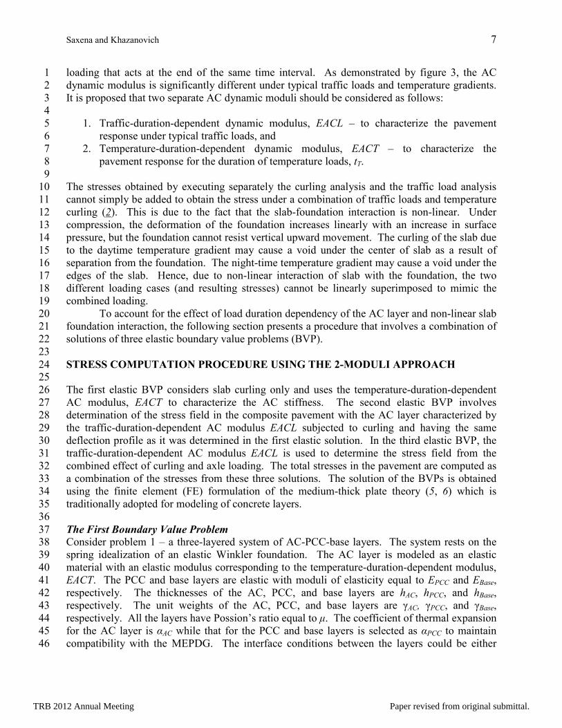
fully bonded or unbonded. The pavement system of problem 1 is subjected to a positive 1
temperature gradient T(z) as shown in figure 4(a). 2
3
4 Figure 4. (a) System 1 under positive temperature gradient T(z) only, (b) system 2 under 5
fictitious force Ffict, (c) System 2 under mid-slab traffic load F and fictitious force Ffict. 6
7
The deflection profile of the slab under the temperature gradient T(z) is recorded. The stress at 8
the bottom of the PCC layer at the mid-slab location under temperature gradient T(z) is denoted 9
as σ1. The equilibrium equation for system 1 can be expressed as follows (6): 10
11
[ ]{ } { }thermFK =11 δ (7) 12
13
where 14
[K1] is the global stiffness matrix for system 1 with temperature-duration-dependent AC 15
modulus EACT, 16
{Ftherm} is the global force vector due to temperature distribution T(z), and 17
{δ} is the global displacement vector of system 1. 18
19
The displacements of the slab, δ1 can be written as: 20
21
(8) 22
23
AC (EACT)
PCC (EPCC)
Base (EBase)
T(z)
AC (EACL)
PCC (EPCC)
Base (EBase)
Fictitious Force, Ffict
AC (EACL)
PCC (EPCC)
Base (EBase)
Fictitious Force, Ffict
Traffic load, F
+
(a) (b)
(c)
{ } [ ] { }thermFK1
11
−=δ
TRB 2012 Annual Meeting Paper revised from original submittal.
Saxena and Khazanovich 9
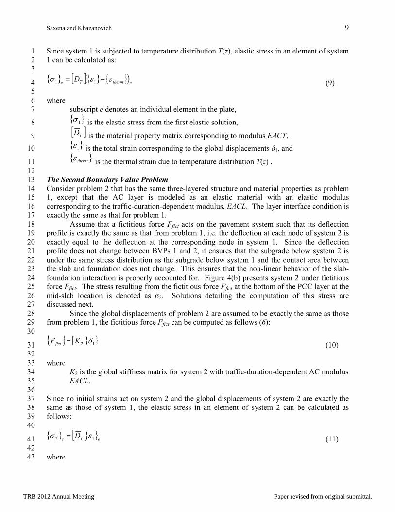
Since system 1 is subjected to temperature distribution T(z), elastic stress in an element of system 1
1 can be calculated as: 2
3
(9) 4
5
where 6
subscript e denotes an individual element in the plate, 7
is the elastic stress from the first elastic solution, 8
is the material property matrix corresponding to modulus EACT, 9
is the total strain corresponding to the global displacements δ1, and 10
is the thermal strain due to temperature distribution T(z) . 11
12
The Second Boundary Value Problem 13 Consider problem 2 that has the same three-layered structure and material properties as problem 14
1, except that the AC layer is modeled as an elastic material with an elastic modulus 15
corresponding to the traffic-duration-dependent modulus, EACL. The layer interface condition is 16
exactly the same as that for problem 1. 17
Assume that a fictitious force Ffict acts on the pavement system such that its deflection 18
profile is exactly the same as that from problem 1, i.e. the deflection at each node of system 2 is 19
exactly equal to the deflection at the corresponding node in system 1. Since the deflection 20
profile does not change between BVPs 1 and 2, it ensures that the subgrade below system 2 is 21
under the same stress distribution as the subgrade below system 1 and the contact area between 22
the slab and foundation does not change. This ensures that the non-linear behavior of the slab-23
foundation interaction is properly accounted for. Figure 4(b) presents system 2 under fictitious 24
force Ffict. The stress resulting from the fictitious force Ffict at the bottom of the PCC layer at the 25
mid-slab location is denoted as σ2. Solutions detailing the computation of this stress are 26
discussed next. 27
Since the global displacements of problem 2 are assumed to be exactly the same as those 28
from problem 1, the fictitious force Ffict can be computed as follows (6): 29
30
(10) 31
32
where 33
K2 is the global stiffness matrix for system 2 with traffic-duration-dependent AC modulus 34
EACL. 35
36
Since no initial strains act on system 2 and the global displacements of system 2 are exactly the 37
same as those of system 1, the elastic stress in an element of system 2 can be calculated as 38
follows: 39
40
(11) 41
42
where 43
{ } [ ]{ } { }( )ethermTe
D εεσ −= 11
{ }1σ
[ ]TD
{ }1ε
{ }thermε
{ } [ ]{ }12 δKF fict =
{ } [ ]{ }eLe
D 12 εσ =
TRB 2012 Annual Meeting Paper revised from original submittal.
Saxena and Khazanovich 10
is the elastic stress from the second elastic solution, and 1
is the material property matrix corresponding to modulus EACL. 2
3
The Third Boundary Value Problem 4 Since system 2 characterizes the AC layer with an elastic modulus corresponding to the traffic-5
duration-dependent modulus, EACL, the traffic load F can be superimposed on top of the 6
fictitious loading Ffict. Therefore, in the third elastic problem, system 2 is loaded by a total load 7
consisting of traffic load F and fictitious load Ffict as shown in figure 4(c). The stress at the 8
bottom of the PCC layer at the mid-slab location due to the total load is denoted as σ3. The 9
global displacements δ under a combination of loads can be computed as follows: 10
11
(12) 12
13
where 14
{F} is the global force vector due to traffic loads, and 15
{Ffict} is the global fictitious force vector from the second elastic solution. 16
17
The elastic stress from the third elastic problem can be calculated as follows: 18
19
(13) 20
21
where 22
is the elastic stress from the third elastic solution, and 23
is the total strain corresponding to the global displacements δ. 24
25
Combined Stress 26 Finally, to obtain the stress distribution in the pavement due to the combined effects of 27
temperature and traffic loading, solutions of the three elastic problems are combined as follows: 28
29
)( 2312 σσσσ −+=M (14) 30
31
where 32
σ2M is the combined stress at a given location, 33
σ1 is the stress at the given location from the first elastic solution, 34
σ2 is the stress at the given location from the second elastic solution, and 35
σ3 is the stress at the given location from the third elastic solution. 36
37
The stress solution obtained using the 2-moduli approach is compared with simple examples 38
presented below. In order to maintain compatibility with the MEPDG, the AC moduli are 39
computed using the existing MEPDG procedure for calculating the dynamic modulus of the AC 40
layer. However, any other existing procedure for characterizing the viscoelastic constitutive law 41
for the AC layer could also be used. 42
43
{ }2σ
[ ]LD
{ } [ ] { } { }( )fictFFK += −1
2δ
{ } [ ]{ }eTLe
D εσ =3
{ }3σ
{ }Tε
TRB 2012 Annual Meeting Paper revised from original submittal.
Saxena and Khazanovich 11
1
2
COMPARISON OF THE STRESS SOLUTION USING THE 2-MODULI APPROACH 3
WITH SIMPLE ADDITION OF THE STRESSES 4
5
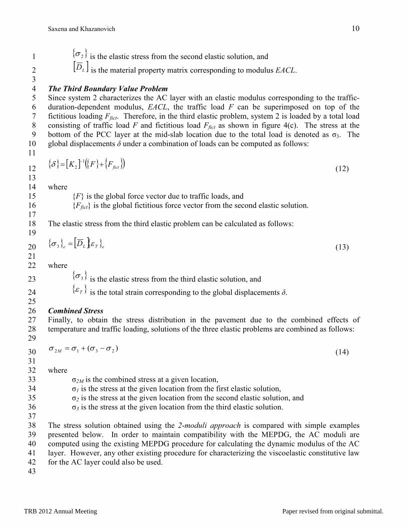
To confirm that the stress in a pavement subjected to the combination of traffic loads and 6
temperature gradients is not the direct addition of stresses computed separately under such loads, 7
a three-layered pavement slab placed on an elastic Winkler foundation is considered. A 15 ft 8
long by 12 ft wide pavement slab is loaded with single-axle dual-wheel (SADW) loads at the 9
edge of the slab as shown in figure 5 (a). The SADW loads have a tire footprint of 7 in x 7 in 10
and tire pressure of 100 psi. A uniform mesh consisting of 6 in x 6 in elements is generated. 11
The modulus of subgrade reaction for the Winkler foundation is equal to 100 psi/in. 12
13
14 Figure 5. Mesh and load configuration for the composite pavement subjected to SADW load at 15
the (a) edges of the slab and (b) center of the slab. 16
17
The material properties for the constituent layers of the composite pavement are presented in 18
table 1. The interface between the AC and PCC layers of the composite pavement is fully 19
bonded while the interface between the PCC and base layers is fully unbonded. 20
21
Table 1. Layer properties for the composite pavement. 22
Layer Thickness,
h (in)
Layer modulus,
E (psi)
Poisson’s
ratio,
µ
Unit weight,
γ (lb/in3)
Coefficient of
thermal expansion,
α (1/°F)
AC 2 EACT = 39448.9
0.15 0.087 1.65E-05 EACL = 2.0E+05
PCC 7 4.0E+06 0.15 0.087 5.50E-06
Base 6 4.0E+04 0.15 0.000 5.50E-06
23
The composite pavement is also subjected to a non-linear night-time temperature distribution 24
given in table 2. 25
26
(a) (b)
12”
12”
72”
144”
180”
144”
180”
12”
12”
72”
12”
12”
72”
TRB 2012 Annual Meeting Paper revised from original submittal.
Saxena and Khazanovich 12
1
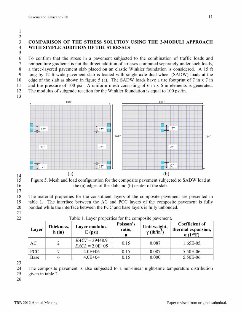
Table 2. Temperature profile for the composite pavement. 2
Layer No. of temperature data points
1 2 3 4 5 6 7 8 9 10 11
AC
Reference temperature = 55.90 °F
Depth,
In 0.0 0.5 1.0 1.5 2.0
Temp.,
°F 40.9 46.0 49.0 52.9 57.8
PCC
Reference temperature = 55.90 °F
Depth,
in 0.0 0.7 1.4 2.1 2.8 3.5 4.2 4.9 5.6 6.3 7.0
Temp.,
°F 57.8 60.2 62.5 64.7 66.9 68.0 70.9 72.8 74.5 76.2 78.8
3
The stress in the pavement is computed using the 2-moduli approach presented above. The 4
stress is also computed when the composite pavement is subjected to (a) the temperature load 5
only, and the AC layer has temperature-duration-dependent modulus EACT and (b) the traffic 6
load only, and the AC layer has traffic-duration-dependent modulus EACL. The combined PCC 7
top stress at the edge of the slab using the 2-moduli approach is compared against the sum of 8
stresses from case (a) and case (b). The results are presented in table 3 below. 9
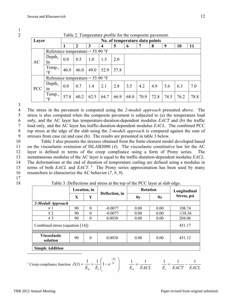
Table 3 also presents the stresses obtained from the finite element model developed based 10
on the viscoelastic extension of ISLAB2000 (4). The viscoelastic constitutive law for the AC 11
layer is defined in terms of the creep compliance using a form of Prony series. The 12
instantaneous modulus of the AC layer is equal to the traffic-duration-dependent modulus EACL. 13
The deformations at the end of duration of temperature curling are defined using a modulus in 14
terms of both EACL and EACT. 1 The Prony series approximation has been used by many 15
researchers to characterize the AC behavior (7, 8, 9). 16
17
Table 3. Deflections and stress at the top of the PCC layer at slab edge. 18
Location, in
Deflection, in Rotation Longitudinal
Stress, psi X Y θy θx
2-Moduli Approach
# 1 90 0 -0.0077 0.00 0.00 108.74
# 2 90 0 -0.0077 0.00 0.00 -138.36
# 3 90 0 0.0038 0.00 0.00 204.06
Combined stress (equation [14]) 451.17
Viscoelastic
solution 90 0 0.0038 0.00 0.00 451.12
Simple Addition
1 Creep compliance function
−+=
−
1
1
111
)(10
ηtE
eEE
tJ
EACLE
11
0
=
EACLEACTE
111
1
−=
TRB 2012 Annual Meeting Paper revised from original submittal.
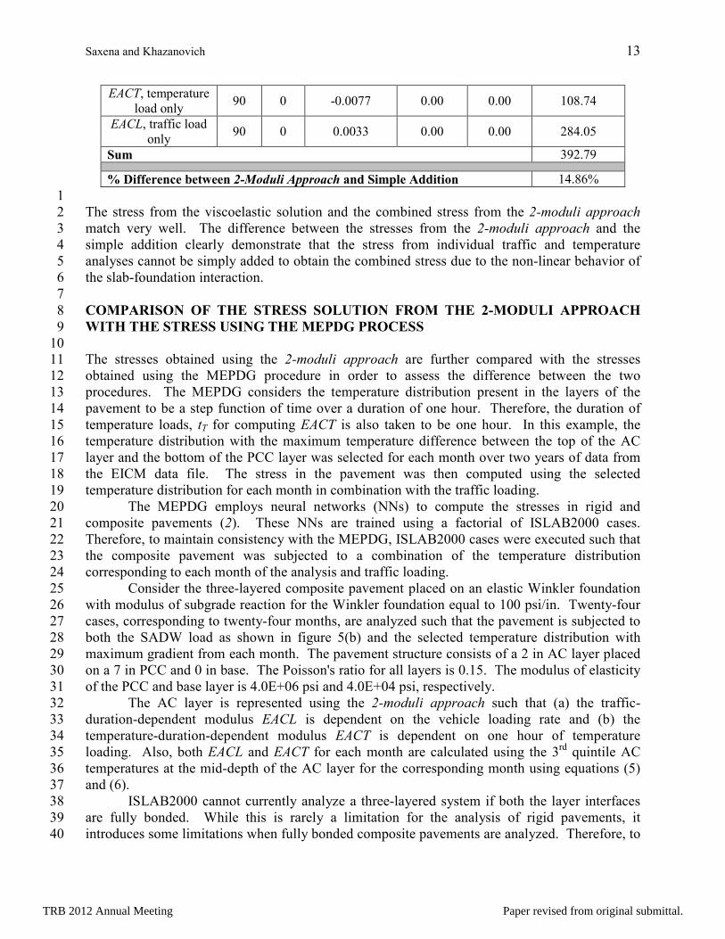
Saxena and Khazanovich 13
EACT, temperature
load only 90 0 -0.0077 0.00 0.00 108.74
EACL, traffic load
only 90 0 0.0033 0.00 0.00 284.05
Sum 392.79
% Difference between 2-Moduli Approach and Simple Addition 14.86%
1
The stress from the viscoelastic solution and the combined stress from the 2-moduli approach 2
match very well. The difference between the stresses from the 2-moduli approach and the 3
simple addition clearly demonstrate that the stress from individual traffic and temperature 4
analyses cannot be simply added to obtain the combined stress due to the non-linear behavior of 5
the slab-foundation interaction. 6
7
COMPARISON OF THE STRESS SOLUTION FROM THE 2-MODULI APPROACH 8
WITH THE STRESS USING THE MEPDG PROCESS 9
10
The stresses obtained using the 2-moduli approach are further compared with the stresses 11
obtained using the MEPDG procedure in order to assess the difference between the two 12
procedures. The MEPDG considers the temperature distribution present in the layers of the 13
pavement to be a step function of time over a duration of one hour. Therefore, the duration of 14
temperature loads, tT for computing EACT is also taken to be one hour. In this example, the 15
temperature distribution with the maximum temperature difference between the top of the AC 16
layer and the bottom of the PCC layer was selected for each month over two years of data from 17
the EICM data file. The stress in the pavement was then computed using the selected 18
temperature distribution for each month in combination with the traffic loading. 19
The MEPDG employs neural networks (NNs) to compute the stresses in rigid and 20
composite pavements (2). These NNs are trained using a factorial of ISLAB2000 cases. 21
Therefore, to maintain consistency with the MEPDG, ISLAB2000 cases were executed such that 22
the composite pavement was subjected to a combination of the temperature distribution 23
corresponding to each month of the analysis and traffic loading. 24
Consider the three-layered composite pavement placed on an elastic Winkler foundation 25
with modulus of subgrade reaction for the Winkler foundation equal to 100 psi/in. Twenty-four 26
cases, corresponding to twenty-four months, are analyzed such that the pavement is subjected to 27
both the SADW load as shown in figure 5(b) and the selected temperature distribution with 28
maximum gradient from each month. The pavement structure consists of a 2 in AC layer placed 29
on a 7 in PCC and 0 in base. The Poisson's ratio for all layers is 0.15. The modulus of elasticity 30
of the PCC and base layer is 4.0E+06 psi and 4.0E+04 psi, respectively. 31
The AC layer is represented using the 2-moduli approach such that (a) the traffic-32
duration-dependent modulus EACL is dependent on the vehicle loading rate and (b) the 33
temperature-duration-dependent modulus EACT is dependent on one hour of temperature 34
loading. Also, both EACL and EACT for each month are calculated using the 3rd
quintile AC 35
temperatures at the mid-depth of the AC layer for the corresponding month using equations (5) 36
and (6). 37
ISLAB2000 cannot currently analyze a three-layered system if both the layer interfaces 38
are fully bonded. While this is rarely a limitation for the analysis of rigid pavements, it 39
introduces some limitations when fully bonded composite pavements are analyzed. Therefore, to 40
TRB 2012 Annual Meeting Paper revised from original submittal.
Saxena and Khazanovich 14
maintain compatibility with ISLAB2000, the thickness of the base layer of the composite 1
pavement is taken to be equal to zero. The stresses obtained using the 2-moduli approach and by 2
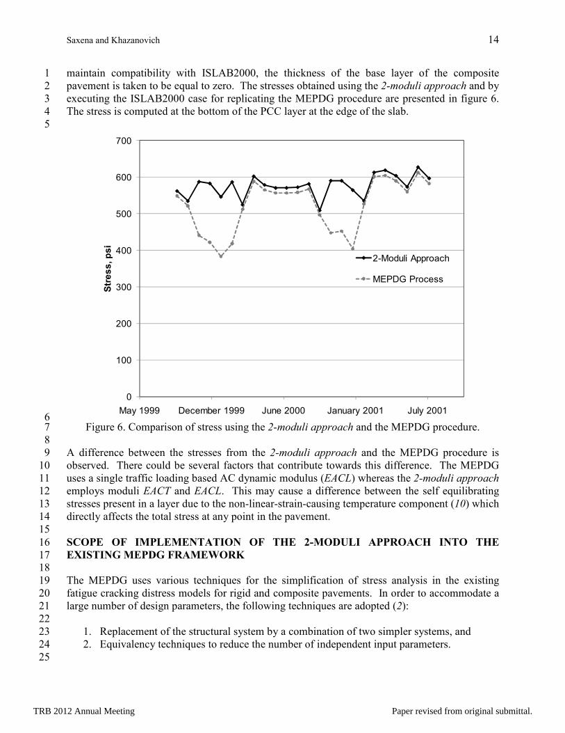
executing the ISLAB2000 case for replicating the MEPDG procedure are presented in figure 6. 3
The stress is computed at the bottom of the PCC layer at the edge of the slab. 4
5
6 Figure 6. Comparison of stress using the 2-moduli approach and the MEPDG procedure. 7
8
A difference between the stresses from the 2-moduli approach and the MEPDG procedure is 9
observed. There could be several factors that contribute towards this difference. The MEPDG 10
uses a single traffic loading based AC dynamic modulus (EACL) whereas the 2-moduli approach 11
employs moduli EACT and EACL. This may cause a difference between the self equilibrating 12
stresses present in a layer due to the non-linear-strain-causing temperature component (10) which 13
directly affects the total stress at any point in the pavement. 14
15
SCOPE OF IMPLEMENTATION OF THE 2-MODULI APPROACH INTO THE 16
EXISTING MEPDG FRAMEWORK 17
18
The MEPDG uses various techniques for the simplification of stress analysis in the existing 19
fatigue cracking distress models for rigid and composite pavements. In order to accommodate a 20
large number of design parameters, the following techniques are adopted (2): 21
22
1. Replacement of the structural system by a combination of two simpler systems, and 23
2. Equivalency techniques to reduce the number of independent input parameters. 24
25
0
100
200
300
400
500
600
700
May 1999 December 1999 June 2000 January 2001 July 2001
Stress, psi
2-Moduli Approach
MEPDG Process
TRB 2012 Annual Meeting Paper revised from original submittal.
Saxena and Khazanovich 15
The MEPDG employs a framework of rapid solutions to predict the stress solution for 1
rigid and composite pavements under traffic loading, temperature distribution, or their 2
combinations (2, 11, 12). The NNs are based on a combination of two simpler systems – 3
systems A and B – to compute stresses in the original multi-slab system. System A is a single 4
slab with length equal to the transverse joint spacing of the original system, width equal to the 5
width of the truck lane in the original system, and thickness equal to the slab thickness of the 6
original system. System A is analyzed for three loading conditions, namely: stress due to axle 7
loading only, curling stress due to equivalent linear temperature loading only, and stress due to 8
combined axle and linear temperature loading. System B is a two-slab system (i.e., single slab 9
with shoulder) that has a sufficiently large slab length to ignore slab size effects, slab width equal 10
to the width of the truck lane in the original system, and thickness equal to the slab thickness of 11
the original system. NNs based on system B accounts for the tire-footprint geometry and the 12
effect of shoulder support. System B considers axle loading but does not consider temperature 13
curling (2). The total stress in the original system is then expressed as a combination of stresses 14
from neural networks NNA and NNB as follows: 15
16
[ ])0()0,(),0(),( *),0(BAAAA
Tot PTTPLTET σσσσσσ +−−+= (15) 17
18
where 19
is the stress in the original multi-slab composite pavement, 20
),0( TAσ , )0,(PAσ , and ),( TPAσ are stresses in system A due to temperature curling 21
only, axle loading only, and combined axle loading and temperature curling, respectively, 22
is the stress in system B when the shoulder provides no edge support, and 23
LTE is the load transfer efficiency between the pavement slab and the shoulder. 24
25
A similar approach is adopted for the development of a MEPDG compatible framework that 26
shall incorporate the stress solution obtained using the 2-moduli approach. The AC layer of the 27
composite pavement system A is represented using the traffic-duration-dependent modulus 28
EACL when the pavement is subjected to the axle load. The AC layer of system A is represented 29
by the temperature-duration-dependent modulus EACT when the pavement is subjected to the 30
temperature distribution. Similar to the total stress obtained using the MEPDG procedure 31
(equation [15]), the stress in the original multi-slab composite system using the 2-moduli 32
approach is related to the stress in systems A and B as follows: 33
34
(16) 35
36
where 37
is the stress in system A due to temperature curling only and is equal to the 38
stress from the first elastic BVP of the 2-moduli approach, 39
and are stresses in system A due to combined axle loading and 40
temperature curling; and are equal to the stresses from the second and third elastic BVPs 41
of the 2-moduli approach, respectively, 42
is the stress in system A due to axle loading only, and 43
Totσ
)0(Bσ
( )[ ])0()0,(*),0(*),(*),0( 231
BAAAA
Tot PTTPLTET σσσσσσ +−−+=
),0(1 TAσ
*),0(2 TAσ *),(3 TPAσ
)0,(PAσ
TRB 2012 Annual Meeting Paper revised from original submittal.
Saxena and Khazanovich 16
is the stress in system B when the shoulder provides no edge support. 1
2
The similarities between equations (15) and (16) imply that minimum modifications to the 3
existing MEPDG neural network framework are required in order to implement the stress 4
solution technique based on the 2-moduli approach. 5
6
CONCLUSIONS 7
8
Composite pavements are complex structures incorporating both asphalt and portland cement 9
concrete layers. Composite pavement behavior exhibits features of both rigid and flexible 10
pavements. Because of this, a structural analysis of composite pavements is a challenging 11
program. This research was concentrated on the improvement of the structural modeling of 12
stress analysis for predicting the PCC fatigue cracking compatible with the existing MEPDG 13
framework. The summary of the research findings is presented below. 14
15
• The use of a single load duration-dependent AC dynamic modulus to characterize the 16
behavior of the AC layer seems insufficient for composite pavements subjected to a 17
combination of traffic loads and temperature curling, as a significant difference was 18
found in the load-duration dependent AC dynamic modulus when a composite pavement 19
is subjected to typical traffic loads and to one hour of temperature loads. 20
• A stress computation procedure was developed to calculate stresses in the composite 21
pavement subjected to a combination of traffic loads and temperature curling using two 22
load duration-dependent AC moduli. In this research, the AC moduli were computed 23
using the existing MEPDG procedure for calculating the dynamic modulus of the AC 24
layer in order to maintain compatibility with the MEPDG. However, any other existing 25
procedure for characterizing the viscoelastic constitutive law for the AC layer could also 26
be used. 27
• The stresses computed using the 2-moduli approach and the MEPDG procedure are 28
found to be significantly different when composite pavements are subjected to a 29
combination of traffic loading and temperature curling. This issue needs to be 30
investigated further. 31
• A framework for the implementation of the proposed stress procedure into the MEPDG 32
was developed such that minimum modifications to the existing MEPDG framework are 33
required. The proposed stress computation procedure can be directly implemented into 34
the MEPDG for predicting fatigue cracking in composite pavements. 35
36
REFERENCES 37
38
1. Lytton R. L., Tsai F. L., Lee S., Luo R., Hu S., and Zhou F. 2010. Models for Predicting 39
Reflection Cracking of Hot-Mix Asphalt Overlays. NCHRP Report 669. National 40
Cooperative Highway Research Program, Transporation Research Board, Washington 41
D.C. 42
2. American Association of State Highway and Transportation Officials. 2008. Mechanistic-43
Empirical Pavement Design Guide, Interim Edition: A Manual of Practice. Washington, 44
D.C. 45
)0(Bσ
TRB 2012 Annual Meeting Paper revised from original submittal.
Saxena and Khazanovich 17
3. Pellinen T. K. and Witczak M. W. 2002. Stress Dependent Master Curve Construction for 1
Dynamic (Complex) Modulus. Journal of the Association of Asphalt Paving 2
Technologists. 3
4. Saxena P. 2011. Cracking of the PCC Layer in Composite Pavement. Ph.D. Dissertation, 4
University of Minnesota, Minneapolis, MN. 5
5. Timoshenko S. P. and Woinowsky-Krieger S. 1959. Theory of Plates and Shells. 2nd
6
edition, McGraw-Hill, NY. 7
6. Zienkiewicz O. C. and Taylor R. L. 1967. Finite Element Method for Solid and Structural 8
Mechanics, 1st Edition, Elsevier. 9
7. Daniel J. S., Kim Y. R., and Lee H. 1998. Effects of Aging on Viscoelastic Properties of 10
Asphalt-Aggregate Mixtures. Transportation Research Record, Vol. 1630, pp. 21-27. 11
8. Di Bendetto H., Olard F., Sauzeat C., and Delaporte B. 2004. Viscoelastic Behavior of 12
Bituminous Materials: From Binders to Mixes. International Journal of Road Materials 13
and Pavement Design, Vol. 5, Special Issue, pp. 163-202. 14
9. Marasteanu M., Velasquez R., Falchetto A. C., and Zofka A. 2009. Development of a 15
Simple Test to Determine the Low Temperature Creep Compliance of Asphalt Mixtures. 16
IDEA Program Transportation Research Board, National Research Council. 17
10. Ioannides A. and L. Khazanovich. 1998. Nonlinear Temperature Effects in Multi-18
Layered Concrete Pavements, ASCE Journal of Transportation Engineering, 124(2):128–19
136. 20
11. Banan M. and Hjelmstad. 1994. Data-Based Mathematical Modeling: Development and 21
Application. SRS No. 590, Civil Engineering Studies, University of Illinois, Urbana, IL. 22
12. Khazanovich L. and Roessler J. 1997. DIPLOBACK: a Neural Networks-Based 23
Backcalculation Program for Composite Pavements. Transportation Research Record 24
1570, Washington D. C. 25
26
TRB 2012 Annual Meeting Paper revised from original submittal.