Embed Size (px)
Citation preview
qMembers of the Innovative Manufacturing Initiative (IMI) Re-search Programme. IMI academic members also include researchersfrom the universities of Glasgow and Cardi!. Industrial membersinclude B.P. Amoco, Johnson Matthey, ICI Synetix and MSI.
*Correspondence address. In"neum UK Ltd., PO BOX 1, MiltonHill, Abingdon OX13 6BB, UK. Tel.: #44-(0)-1235-545993; fax: #44-(0)-1235-545939.
E-mail address: sanjeev.sharma@in"neum.com (S. Sharma).
Chemical Engineering Science 56 (2001) 587}595
Determination of bed voidage using water substitutionand 3D magnetic resonance imaging, bed density and pressure drop
in packed-bed reactorsq
S. Sharma!,*, M. D. Mantle", L. F. Gladden", J. M. Winterbottom!
!University of Birmingham, Department of Chemical Engineering, Edgbaston, Birmingham B15 2TT, UK"University of Cambridge, Department of Chemical Engineering, Pembroke Street, Cambridge CB2 3RA, UK
Abstract
Using a water substitution method to determine bed voidage, an independent relationship between bed height and bed voidage wasobserved for the trilobe (virgin and crushed) and cylindrical alumina supports. Typical bed voidage values of 0.49}0.51 (virgin trilobe).0.46}0.52 (crushed trilobe) and 0.28}0.31 (cylindrical) were observed within 0.1 and 0.19 m i.d. columns. However, bed voidage valueswere approximately 6% larger in the 0.05 m i.d. column and could be attributed to a greater extent of wall zone voidage. Densepacking of the columns in all cases resulted in a decrease in bed voidage which had signi"cant e!ects on bed density and columnpressure drop. In addition to the water substitution measurements of bed voidage, three-dimensional magnetic resonance imaging(MRI) data were used in conjunction with digital image analysis techniques to obtain one-dimensional radial pro"les of voidage fromcomparable alumina catalyst support material. Similar results and trends in voidage values between the water substitution methodand those obtained from MRI data are evident. In all cases, the analysis of the MRI data yields voidage values that are consistentlyhigher than those obtained from water substitution measurements. ( 2001 Elsevier Science Ltd. All rights reserved.
Keywords: Packed bed; Bed voidage; Bed density; Pressure drop; MRI
1. Introduction
The speci"cation for sulphur levels in gasoline havebeen forced to be continuously reduced due to regulatorypressures, from the pre 1996 level of 2000 ppm, to500 ppm up to 1996. The current requirements by the USEnvironmental Protection Agency for a reduction ingasoline sulphur levels from the current average level of330 ppm to an average 80 ppm by 2005 (Article, 1999,May 10) will require re"ners to undertake deeper hy-drodesulphurisation, thereby requiring maximum utilis-ation of their current units. This could be achieved byoptimising existing units using better catalysts, in terms
of achieving higher reactivity per unit volume with higherselectivity, in conjunction with optimum catalyst supportdesign (Sutikno, 1999). Reactor utilisation may also bemaximised by increasing the volume activity by improvingthe catalyst loading procedure. In existing hydrotreatingunits, the reactor capacity can be increased up to 25% byapplying a dense loading technique (Nooy, 1984) and whenused in conjunction with polylobed catalysts, obvious ad-vantages for process optimisation occur. The higher ex-ternal surface area for such supports (as compared tocylindrical pellets) ensures better accessibility to the innersurface of the catalyst, and dense loading allows morecatalytic activity in a given reactor volume (Cooper, Donnis& Moyse, 1986). However, typical disadvantages that occurusing this technology include (i) a less densely packed bedwhen using polylobed catalysts thus leading to a reductionin volume activity and (ii) higher initial pressure dropthrough the bed when using dense loading.
As part of a multidisciplinary research team involvingacademic and industrial chemists, chemical engineers, ma-terial scientists and molecular modellers, the InnovativeManufacturing Initiative (IMI) research programme was
0009-2509/01/$ - see front matter ( 2001 Elsevier Science Ltd. All rights reserved.PII: S 0 0 0 9 - 2 5 0 9 ( 0 0 ) 0 0 2 6 4 - 5
initiated to address (i) the in#uence of catalyst form onreactor performance and (ii) catalyst structure on activityand selectivity and their dependence on material process-ing. The former topic of interest was investigated at theuniversity of Birmingham and Cambridge and centred onthe determination of bed voidage, bed density and pres-sure drop in packed bed reactors using commercial cata-lyst support material. Two types of alumina supportmaterial were investigated, namely a trilobe support(1.3 mm diameter) as used within hydrotreating reactorsand a cylindrical support (3 mm diameter) commonlyused within trickle-bed reactors in the "ne chemicalmanufacturing sector.
2. Experimental
2.1. Bed voidage, Bed density and Pressure drop
The virgin (as received) trilobe alumina support mater-ial (Packing I) was initially characterised in terms of itsparticle length distribution. Random samples were scan-ned using a #atbed scanner attached to a PC and analysedusing PC Image, which was calibrated prior to use. Inorder to obtain a representative sample set the procedurewas repeated 20 times using a fresh batch of supportmaterial for each analysis. In order to simulate particlelengths as received after catalyst regeneration, the virginsupport material was partly crushed in a rotating drum.Approximately 0.1 kg of the virgin support material wasplaced with 10 solid ceramic balls (with each ball ofdiameter 0.03 m; mass 0.03 kg) and gently rotated fora "xed period of 15 min. The partly crushed supportmaterial (packing III) was then sieved to remove any "nes.Comparative bed voidage and bed density measurementswere undertaken using cylindrical pressed alumina pelletsof uniform dimension (3.0 mm diameter and length) andwere used as received without any further mechanicaltreatment (Packing II).
Bed voidage studies were undertaken using the trilobe(virgin and crushed) and cylindrical support material in1 m one acrylic columns of internal diameter 0.05 m(2 in), 0.1 m (4 in) and 0.19 m (7.5 in).
The support material due to its porosity waspresoaked for 2 h in water before any measurements ofbed voidage or bed density were undertaken. The bedswere prepared by using the pre-wetted samples (drainedof excess water) and slowly added into the column untilthe desired bed height was achieved. This mode of charg-ing the column will be classed as &dumped' where noattempt was made to induce settling of the packing. Inthe case of obtaining a &dense' packed bed, the base of the"lled column was gently tapped on a #at surface for10, 20, 30 or 40 times and the reduced bed height wasnoted. Initial bed heights studied for both the dumpedand dense packed beds were 0.3, 0.6 and 0.9 m. The total
fractional volume of the bed occupied by the void spaceswas then obtained by water substitution (gravimetricmethod) thereby giving a direct indication of the meanoverall bed voidage. Slow addition of the water onto thesides of the column was imperative in order to allowtrapped air pockets to be released and to prevent disrup-tion of the top layer of packing. Using the 0.05, 0.1 and0.19 m i.d. columns corresponded to a column to particlediameter ratio (aspect ratio) of 38.5, 76.9 and 146.2 for thetrilobe support and 16.7, 33 and 63 for the cylindricalsupport, respectively.
A more representative bed density value was obtainedusing the wetted particles as opposed to using the dryparticles. In this instance, the mass of support required toobtain an initial bed height was obtained for the threecolumn diameters of interest. Bed density values werealso obtained for dense packed beds whereby the columnwas packed using the method described previously.
The experimental apparatus used to determine pres-sure drop is shown schematically in Fig. 1. Pressure dropmeasurements using the trilobe support material wereundertaken in a glass QVF column of internal diameter0.1 m and length 1.4 m. Column pressure down thelength of the column was obtained from 6 pressure tap-pings attached to standard Bourdon pressure gauges,each separated by a distance of 0.19 m. Calibrated adhes-ive measuring tape was attached to the side of the columnin order to determine the bed height. The reactor wasoperated in co-current down#ow operation using watervolumetric #owrates within the range of 12}30 l/min andair #owrates within the range of 20}80 l/min. Gas andliquid were introduced into the reactor via a single ori"ceof diameter 0.025 m. The typical operating temperaturewas approximately 203C with a gas inlet pressure of303.9 kPa.
The reactor was charged with the trilobe support mater-ial by pouring the material from top of the reactor ontoinert plastic Pall rings (bed height 0.2 m), which were usedto prevent the smaller trilobe particles from being #ushedthrough the column. The bed height of the trilobe supportwas varied within the ranges of 0.28}0.64 m, such that thebed was above and below pressure tappings. In order toachieve better wetting e$ciency and liquid distribution,another layer of plastic Pall rings (bed height 0.2 m) wasplaced on top of the trilobe support. A dense packingarrangement was obtained by slowly charging the trilobesupport through a 0.025 m i.d. #exible tube in a rotationalmanner and by gently tapping the packing at regular inter-vals with the end of the tube. The packed bed was pre-wetted prior to the pressure drop measurements by operat-ing the reactor at a liquid #owrate of 20 l/min for 30 min.
2.2. Column preparation and MRI experimental
All MRI experiments were performed on a Bruker Spec-trospin DMX 200 MHz MRI spectrometer operating at
588 S. Sharma et al. / Chemical Engineering Science 56 (2001) 587}595
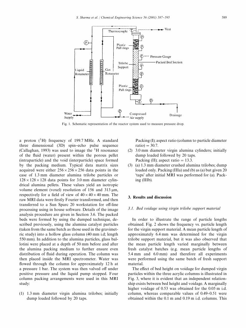
Fig. 1. Schematic representation of the reactor system used to measure pressure drop.
a proton (1H) frequency of 199.7 MHz. A standardthree dimensional (3D) spin}echo pulse sequence(Callaghan, 1993) was used to image the 1H resonanceof the #uid (water) present within the porous pellet(intraparticle) and the void (interparticle) space formedby the packing medium. Typical data matrix sizesacquired were either 256]256]256 data points in thecase of 1.3 mm diameter alumina trilobe particles or128]128]128 data points for 3.0 mm diameter cylin-drical alumina pellets. These values yield an isotropicvolume element (voxel) resolution of 156 and 313 lm,respectively for a "eld of view of 40]40]40 mm. Theraw MRI data were "rstly Fourier transformed, and thentransferred to a Sun Sparc 20 workstation for o!-lineprocessing using in house software. Details of the imageanalysis procedure are given in Section 3.6. The packedbeds were formed by using the dumped technique, de-scribed previously, using the alumina catalyst particles(taken from the same batch as those used in the gravimet-ric study) into a hollow glass column (40 mm i.d; length550 mm). In addition to the alumina particles, glass bal-lotini were placed at a depth of 50 mm before and afterthe alumina packing medium to further ensure evendistribution of #uid during operation. The column wasthen placed inside the MRI spectrometer. Water was#owed through the column for approximately 12 h ata pressure 1 bar. The system was then valved o! underpositive pressure and the liquid pump stopped. Fourcolumn packing arrangements were used in this MRIstudy:
(1) 1.3 mm diameter virgin alumina trilobes; initiallydump loaded followed by 20 taps.
Packing (I); aspect ratio (column to particle diameterratio)"30.7.
(2) 3.0 mm diameter virgin alumina cylinders; initiallydump loaded followed by 20 taps.Packing (II); aspect ratio"13.3.
(3) (a) 1.3 mm diameter crushed alumina trilobes; dumploaded only. Packing (IIIa) and (b) as (a) but given 20&taps' after initial MRI was performed for (a). Pack-ing (IIIb).
3. Results and discussion
3.1. Bed voidage using virgin trilobe support material
In order to illustrate the range of particle lengthsobtained. Fig. 2 shows the frequency vs. particle lengthfor the virgin support material. A mean particle length ofapproximately 6.4 mm was determined for the virgintrilobe support material, but it was also observed thatthe mean particle length varied marginally betweenfresh catalyst batches (e.g. mean particle lengths of5.4 mm and 6.0 mm) and therefore all experimentswere performed using the same batch of fresh supportmaterial.
The e!ect of bed height on voidage for dumped virginparticles within the three acrylic columns is illustrated inFig. 3, where it is evident that an independent relation-ship exists between bed height and voidage. A marginallyhigher voidage of 0.53 was obtained for the 0.05 m i.d.column, whereas comparable values of 0.49}0.51 wereobtained within the 0.1 m and 0.19 m i.d. columns. This
S. Sharma et al. / Chemical Engineering Science 56 (2001) 587}595 589
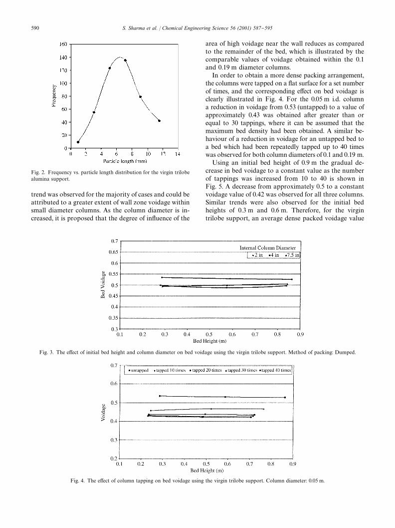
Fig. 2. Frequency vs. particle length distribution for the virgin trilobealumina support.
Fig. 3. The e!ect of initial bed height and column diameter on bed voidage using the virgin trilobe support. Method of packing: Dumped.
Fig. 4. The e!ect of column tapping on bed voidage using the virgin trilobe support. Column diameter: 0.05 m.
trend was observed for the majority of cases and could beattributed to a greater extent of wall zone voidage withinsmall diameter columns. As the column diameter is in-creased, it is proposed that the degree of in#uence of the
area of high voidage near the wall reduces as comparedto the remainder of the bed, which is illustrated by thecomparable values of voidage obtained within the 0.1and 0.19 m diameter columns.
In order to obtain a more dense packing arrangement,the columns were tapped on a #at surface for a set numberof times, and the corresponding e!ect on bed voidage isclearly illustrated in Fig. 4. For the 0.05 m i.d. columna reduction in voidage from 0.53 (untapped) to a value ofapproximately 0.43 was obtained after greater than orequal to 30 tappings, where it can be assumed that themaximum bed density had been obtained. A similar be-haviour of a reduction in voidage for an untapped bed toa bed which had been repeatedly tapped up to 40 timeswas observed for both column diameters of 0.1 and 0.19 m.
Using an initial bed height of 0.9 m the gradual de-crease in bed voidage to a constant value as the numberof tappings was increased from 10 to 40 is shown inFig. 5. A decrease from approximately 0.5 to a constantvoidage value of 0.42 was observed for all three columns.Similar trends were also observed for the initial bedheights of 0.3 m and 0.6 m. Therefore, for the virgintrilobe support, an average dense packed voidage value
590 S. Sharma et al. / Chemical Engineering Science 56 (2001) 587}595
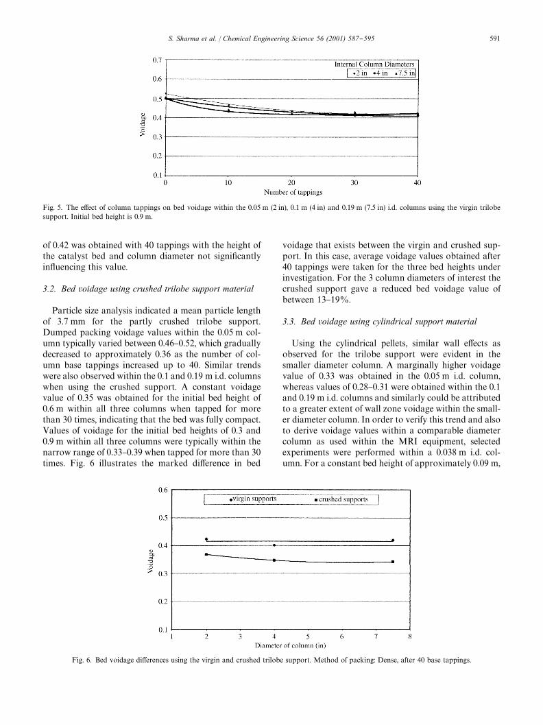
Fig. 5. The e!ect of column tappings on bed voidage within the 0.05 m (2 in), 0.1 m (4 in) and 0.19 m (7.5 in) i.d. columns using the virgin trilobesupport. Initial bed height is 0.9 m.
Fig. 6. Bed voidage di!erences using the virgin and crushed trilobe support. Method of packing: Dense, after 40 base tappings.
of 0.42 was obtained with 40 tappings with the height ofthe catalyst bed and column diameter not signi"cantlyin#uencing this value.
3.2. Bed voidage using crushed trilobe support material
Particle size analysis indicated a mean particle lengthof 3.7 mm for the partly crushed trilobe support.Dumped packing voidage values within the 0.05 m col-umn typically varied between 0.46}0.52, which graduallydecreased to approximately 0.36 as the number of col-umn base tappings increased up to 40. Similar trendswere also observed within the 0.1 and 0.19 m i.d. columnswhen using the crushed support. A constant voidagevalue of 0.35 was obtained for the initial bed height of0.6 m within all three columns when tapped for morethan 30 times, indicating that the bed was fully compact.Values of voidage for the initial bed heights of 0.3 and0.9 m within all three columns were typically within thenarrow range of 0.33}0.39 when tapped for more than 30times. Fig. 6 illustrates the marked di!erence in bed
voidage that exists between the virgin and crushed sup-port. In this case, average voidage values obtained after40 tappings were taken for the three bed heights underinvestigation. For the 3 column diameters of interest thecrushed support gave a reduced bed voidage value ofbetween 13}19%.
3.3. Bed voidage using cylindrical support material
Using the cylindrical pellets, similar wall e!ects asobserved for the trilobe support were evident in thesmaller diameter column. A marginally higher voidagevalue of 0.33 was obtained in the 0.05 m i.d. column,whereas values of 0.28}0.31 were obtained within the 0.1and 0.19 m i.d. columns and similarly could be attributedto a greater extent of wall zone voidage within the small-er diameter column. In order to verify this trend and alsoto derive voidage values within a comparable diametercolumn as used within the MRI equipment, selectedexperiments were performed within a 0.038 m i.d. col-umn. For a constant bed height of approximately 0.09 m,
S. Sharma et al. / Chemical Engineering Science 56 (2001) 587}595 591
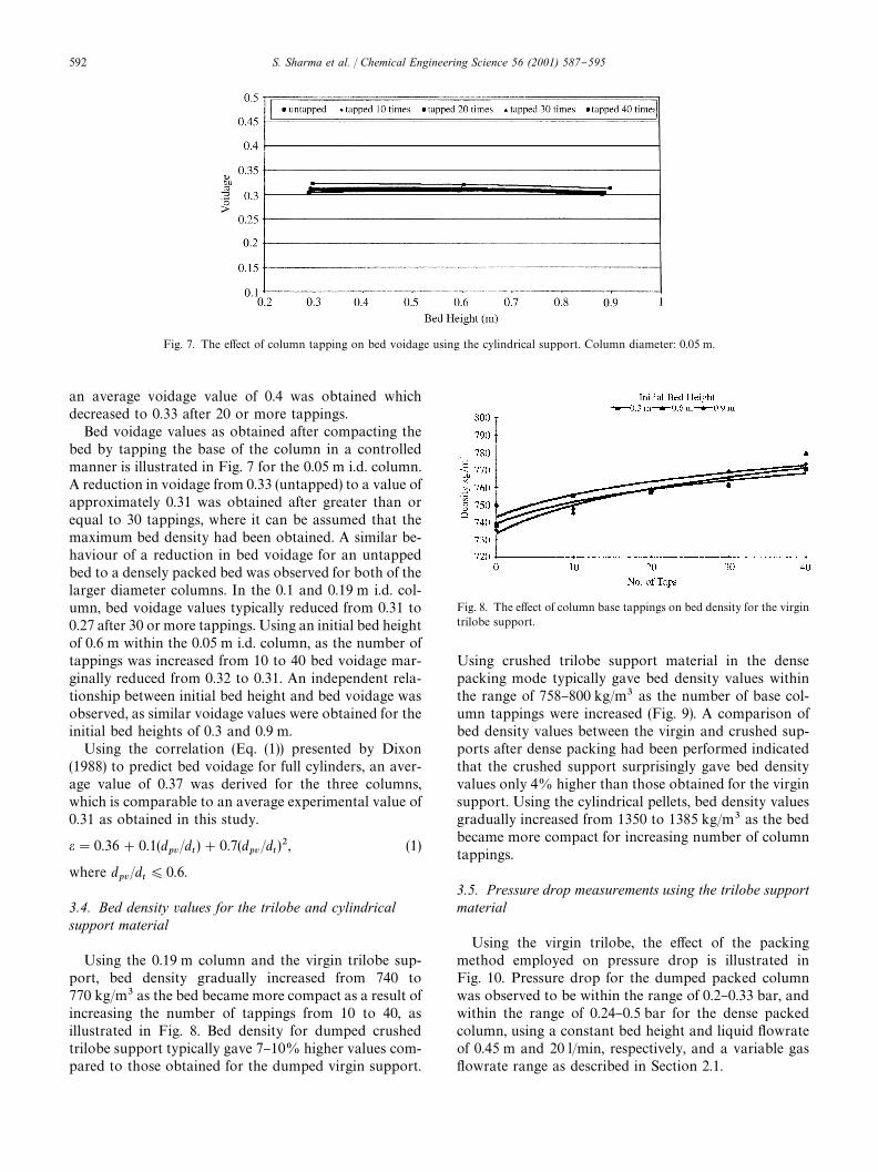
Fig. 7. The e!ect of column tapping on bed voidage using the cylindrical support. Column diameter: 0.05 m.
Fig. 8. The e!ect of column base tappings on bed density for the virgintrilobe support.
an average voidage value of 0.4 was obtained whichdecreased to 0.33 after 20 or more tappings.
Bed voidage values as obtained after compacting thebed by tapping the base of the column in a controlledmanner is illustrated in Fig. 7 for the 0.05 m i.d. column.A reduction in voidage from 0.33 (untapped) to a value ofapproximately 0.31 was obtained after greater than orequal to 30 tappings, where it can be assumed that themaximum bed density had been obtained. A similar be-haviour of a reduction in bed voidage for an untappedbed to a densely packed bed was observed for both of thelarger diameter columns. In the 0.1 and 0.19 m i.d. col-umn, bed voidage values typically reduced from 0.31 to0.27 after 30 or more tappings. Using an initial bed heightof 0.6 m within the 0.05 m i.d. column, as the number oftappings was increased from 10 to 40 bed voidage mar-ginally reduced from 0.32 to 0.31. An independent rela-tionship between initial bed height and bed voidage wasobserved, as similar voidage values were obtained for theinitial bed heights of 0.3 and 0.9 m.
Using the correlation (Eq. (1)) presented by Dixon(1988) to predict bed voidage for full cylinders, an aver-age value of 0.37 was derived for the three columns,which is comparable to an average experimental value of0.31 as obtained in this study.
e"0.36#0.1(dpv
/dt)#0.7(d
pv/d
t)2, (1)
where dpv
/dt)0.6.
3.4. Bed density values for the trilobe and cylindricalsupport material
Using the 0.19 m column and the virgin trilobe sup-port, bed density gradually increased from 740 to770 kg/m3 as the bed became more compact as a result ofincreasing the number of tappings from 10 to 40, asillustrated in Fig. 8. Bed density for dumped crushedtrilobe support typically gave 7}10% higher values com-pared to those obtained for the dumped virgin support.
Using crushed trilobe support material in the densepacking mode typically gave bed density values withinthe range of 758}800 kg/m3 as the number of base col-umn tappings were increased (Fig. 9). A comparison ofbed density values between the virgin and crushed sup-ports after dense packing had been performed indicatedthat the crushed support surprisingly gave bed densityvalues only 4% higher than those obtained for the virginsupport. Using the cylindrical pellets, bed density valuesgradually increased from 1350 to 1385 kg/m3 as the bedbecame more compact for increasing number of columntappings.
3.5. Pressure drop measurements using the trilobe supportmaterial
Using the virgin trilobe, the e!ect of the packingmethod employed on pressure drop is illustrated inFig. 10. Pressure drop for the dumped packed columnwas observed to be within the range of 0.2}0.33 bar, andwithin the range of 0.24}0.5 bar for the dense packedcolumn, using a constant bed height and liquid #owrateof 0.45 m and 20 l/min, respectively, and a variable gas#owrate range as described in Section 2.1.
592 S. Sharma et al. / Chemical Engineering Science 56 (2001) 587}595
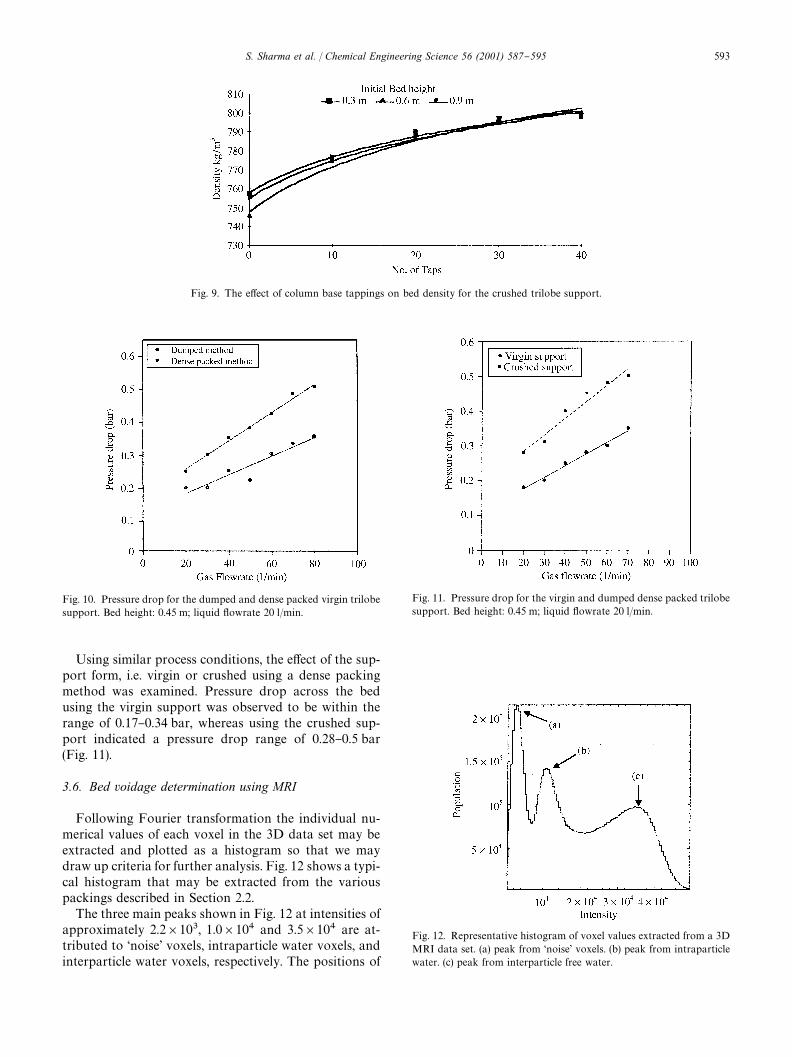
Fig. 9. The e!ect of column base tappings on bed density for the crushed trilobe support.
Fig. 10. Pressure drop for the dumped and dense packed virgin trilobesupport. Bed height: 0.45 m; liquid #owrate 20 l/min.
Fig. 11. Pressure drop for the virgin and dumped dense packed trilobesupport. Bed height: 0.45 m; liquid #owrate 20 l/min.
Fig. 12. Representative histogram of voxel values extracted from a 3DMRI data set. (a) peak from &noise' voxels. (b) peak from intraparticlewater. (c) peak from interparticle free water.
Using similar process conditions, the e!ect of the sup-port form, i.e. virgin or crushed using a dense packingmethod was examined. Pressure drop across the bedusing the virgin support was observed to be within therange of 0.17}0.34 bar, whereas using the crushed sup-port indicated a pressure drop range of 0.28}0.5 bar(Fig. 11).
3.6. Bed voidage determination using MRI
Following Fourier transformation the individual nu-merical values of each voxel in the 3D data set may beextracted and plotted as a histogram so that we maydraw up criteria for further analysis. Fig. 12 shows a typi-cal histogram that may be extracted from the variouspackings described in Section 2.2.
The three main peaks shown in Fig. 12 at intensities ofapproximately 2.2]103, 1.0]104 and 3.5]104 are at-tributed to &noise' voxels, intraparticle water voxels, andinterparticle water voxels, respectively. The positions of
S. Sharma et al. / Chemical Engineering Science 56 (2001) 587}595 593
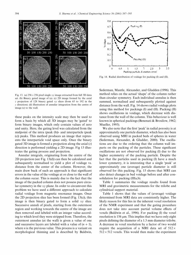
Fig. 13. (a) 256]256 pixel single xy image extracted from full 3D dataset. (b) Binary gated image of (a). (c) 2D image formed by the axialz projection of 128 binary gated xy slices (from 65 to 192 in thez direction). (d) illustration of annular integration from the centre ofimage (c) to the wall.
Fig. 14. Radial distribution of voidage for packing (I) and (II).
these peaks on the intensity scale may then be used toform a basis by which all 3D images may be &gated' toform binary images, which only contain values of zeroand unity. Here, the gating level was calculated from themidpoint of the intra (peak (b))- and interparticle (peak(c)) peaks. This method produces an image that repres-ents the interparticle void space only. Once the binarygated 3D image is formed a projection along the axial (z)direction is performed yielding a 2D image. Fig 13 illus-trates the gating process and projection.
Annular integrals, originating from the centre of the2D projection (see Fig. 13(d)) can then be calculated andsubsequently normalised to yield a plot of voidage vs.distance from the center of the column. However, themain draw back of such an approach is that signi"canterrors in the value of the voidage at or close to the wall ofthe column occur. This is mainly due to the fact that theimage of the packed column does not possess pure circu-lar symmetry in the xy plane. In order to circumvent thisproblem we have used a di!erent approach to calculateradial voidage from magnetic resonance images. Oncethe 2D projection slice has been formed (Fig. 13(c)), thisimage is then binary gated to form a solid xy slice.Successive annuli of pixels, starting from the outermostregion and working towards the centre of the image arethen removed and labeled with an integer value accord-ing to which level they were stripped from. Therefore, theoutermost annulus (at the wall) is given a value of oneand successive layers are labeled with a value of (n#1),where n is the previous value. This process is a variant onmorphological thinning and is described by Baldwin,
Sederman, Mantle, Alexander, and Gladden (1996). Thismethod relies on the actual &shape' of the column ratherthan circular symmetry. Each individual annulus is thensummed, normalised and subsequently plotted againstdistance from the wall. Fig. 14 shows radial voidage plotsusing this method for packings (I) and (II). Packing (II)shows oscillations in voidage, which decrease with dis-tance from the wall of the column. This behaviour is wellknown in spherical packings (Benenati & Brosilow, 1962;Mueller, 1993).
We also note that the "rst &peak' in radial porosity is atapproximately one particle diameter, which has also beenobserved using MRI in packed beds of spheres in water(Sederman, Alexander, & Gladder, 2000). The oscilla-tions are due to the ordering that the column wall im-parts on the packing of the particles. These signi"cantoscillations are not observed for packing (I) due to thehigher asymmetry of the packing particle. Despite thefact that the particles used in packing (I) have a muchlower symmetry, it is interesting that a single &peak' atapproximately one (average) particle diameter is stillobserved for this packing. Fig. 15 shows that MRI canalso detect changes in bed voidage before and after con-solidation for packing (IIIa,b).
Table 1 summaries the voidage results found fromMRI and gravimetric measurements for the trilobe andcylindrical support material.
Table 1 shows that the values of (average) voidagedetermined from MRI data are consistently higher. Thelikely reason for this lies in the inherent voxel resolutionof the NMR experiment and that the gating proceduredoes not take into account partial volume e!ects ofvoxels (Baldwin et al., 1996). For packing (I) the voxelresolution is 156 lm. This implies that we have only eightpixels de"ning the diameter of a 1.3 mm diameter trilobe.A decrease in voxel resolution by a factor of two wouldrequire the acquisition of a MRI data set of 512]512]512 voxels. This would then make the experiment
594 S. Sharma et al. / Chemical Engineering Science 56 (2001) 587}595
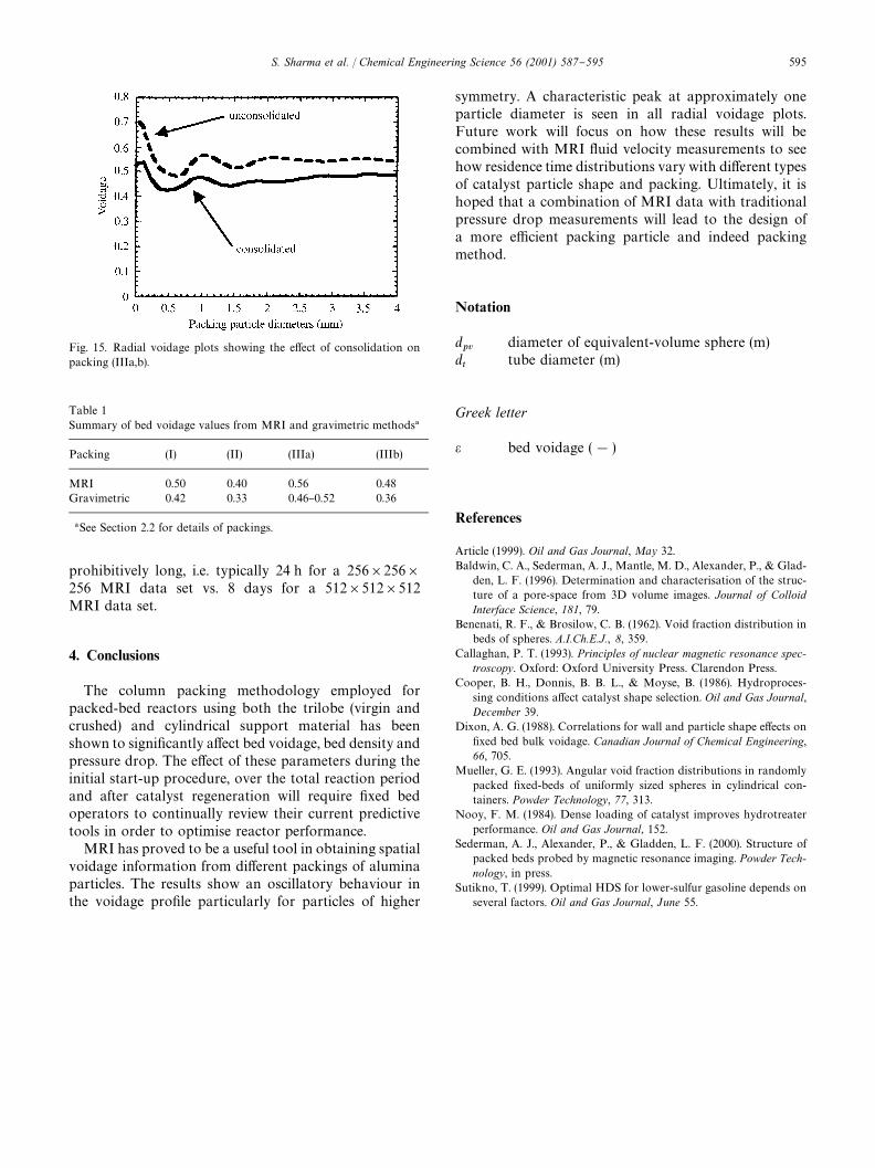
Fig. 15. Radial voidage plots showing the e!ect of consolidation onpacking (IIIa,b).
Table 1Summary of bed voidage values from MRI and gravimetric methods!
Packing (I) (II) (IIIa) (IIIb)
MRI 0.50 0.40 0.56 0.48Gravimetric 0.42 0.33 0.46}0.52 0.36
!See Section 2.2 for details of packings.
prohibitively long, i.e. typically 24 h for a 256]256]256 MRI data set vs. 8 days for a 512]512]512MRI data set.
4. Conclusions
The column packing methodology employed forpacked-bed reactors using both the trilobe (virgin andcrushed) and cylindrical support material has beenshown to signi"cantly a!ect bed voidage, bed density andpressure drop. The e!ect of these parameters during theinitial start-up procedure, over the total reaction periodand after catalyst regeneration will require "xed bedoperators to continually review their current predictivetools in order to optimise reactor performance.
MRI has proved to be a useful tool in obtaining spatialvoidage information from di!erent packings of aluminaparticles. The results show an oscillatory behaviour inthe voidage pro"le particularly for particles of higher
symmetry. A characteristic peak at approximately oneparticle diameter is seen in all radial voidage plots.Future work will focus on how these results will becombined with MRI #uid velocity measurements to seehow residence time distributions vary with di!erent typesof catalyst particle shape and packing. Ultimately, it ishoped that a combination of MRI data with traditionalpressure drop measurements will lead to the design ofa more e$cient packing particle and indeed packingmethod.
Notation
dpv
diameter of equivalent-volume sphere (m)dt
tube diameter (m)
Greek letter
e bed voidage (!)
References
Article (1999). Oil and Gas Journal, May 32.Baldwin, C. A., Sederman, A. J., Mantle, M. D., Alexander, P., & Glad-
den, L. F. (1996). Determination and characterisation of the struc-ture of a pore-space from 3D volume images. Journal of ColloidInterface Science, 181, 79.
Benenati, R. F., & Brosilow, C. B. (1962). Void fraction distribution inbeds of spheres. A.I.Ch.E.J., 8, 359.
Callaghan, P. T. (1993). Principles of nuclear magnetic resonance spec-troscopy. Oxford: Oxford University Press. Clarendon Press.
Cooper, B. H., Donnis, B. B. L., & Moyse, B. (1986). Hydroproces-sing conditions a!ect catalyst shape selection. Oil and Gas Journal,December 39.
Dixon, A. G. (1988). Correlations for wall and particle shape e!ects on"xed bed bulk voidage. Canadian Journal of Chemical Engineering,66, 705.
Mueller, G. E. (1993). Angular void fraction distributions in randomlypacked "xed-beds of uniformly sized spheres in cylindrical con-tainers. Powder Technology, 77, 313.
Nooy, F. M. (1984). Dense loading of catalyst improves hydrotreaterperformance. Oil and Gas Journal, 152.
Sederman, A. J., Alexander, P., & Gladden, L. F. (2000). Structure ofpacked beds probed by magnetic resonance imaging. Powder Tech-nology, in press.
Sutikno, T. (1999). Optimal HDS for lower-sulfur gasoline depends onseveral factors. Oil and Gas Journal, June 55.
S. Sharma et al. / Chemical Engineering Science 56 (2001) 587}595 595