Embed Size (px)
Citation preview

Detectors for particles and radiationAdvanced course for Master students
Spring semester 2010 S7139 5 ECTS points
Tuesday 10:15 to 12:00 - Lectures
Tuesday 16:15 to 17:00 - Exercises

Detectors for particles and radiation
February 23 Kreslo, Gornea Introduction, History of instrumentation
March 2 Kreslo, Gornea Particle-matter electromagnetic interactions
March 9 Kreslo, Gornea Gas detectors : counters
March 16 Kreslo, Gornea Gas detectors : tracking
March 23 Kreslo, Gornea Scintillating detectors :counters
March 30 Kreslo, Gornea Scintillating detectors : tracking
April 6 Bay, Gornea Nuclear emulsions
April 13 Kreslo, Gornea Semiconductor detectors : counters
April 20 Kreslo, Gornea Semiconductor detectors : tracking
April 27 Kreslo, Gornea Semiconductor detectors : tracking
April 27 Kreslo, Gornea Cryogenic liquids : tracking
May 4 Kreslo, Gornea Calorimetry
May 11 Kreslo, Gornea Calorimetry
May 18 Kreslo, Gornea Particle Identification
May 25 Kreslo, Gornea Momentum measurements
June 1 Kreslo, Gornea Discussion + Lab demonstration
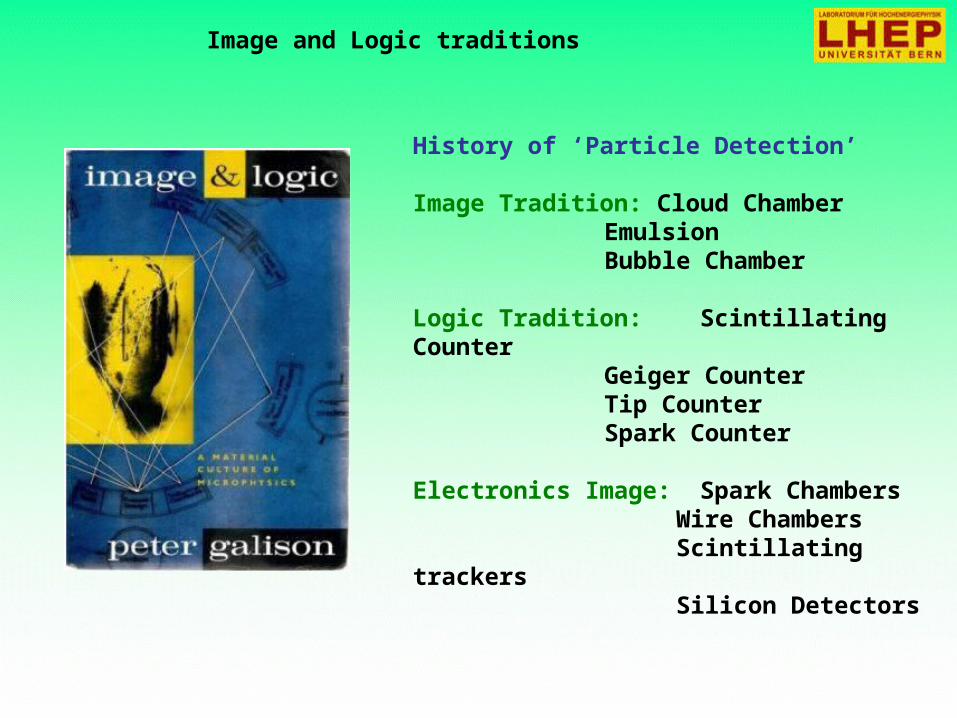
Image and Logic traditions
History of ‘Particle Detection’
Image Tradition: Cloud ChamberEmulsionBubble Chamber
Logic Tradition: Scintillating CounterGeiger CounterTip CounterSpark Counter
Electronics Image: Spark Chambers Wire Chambers Scintillating trackers Silicon Detectors

Introduction, history of instrumentation
1906: Geiger Counter, H. Geiger, E. Rutherford1910: Cloud Chamber, C.T.R. Wilson1912: Tip Counter, H. Geiger1928: Geiger-Müller Counter, W. Müller1929: Coincidence Method, W. Bothe1930: Emulsion, M. Blau1940-1950: Scintillator, Photomultiplier1952: Bubble Chamber, D. Glaser1962: Spark Chamber1968: Multi Wire Proportional Chamber, G. Charpak1979: Time Projection Chamber, D. Nygren1984: Silicon Drift Detectors, E. Gatti & P. Rehak1997: Gas Electron Multiplier, F. Sauli
Etc. etc. etc.
History of instrumentation: Logic detectors (counters)

History of instrumentation: Logic detectors (counters)

E. Rutherford H. Geiger1909
The Geiger counter, later further developed and then calledGeiger-Müller counter
First electrical signal from a particle
pulse

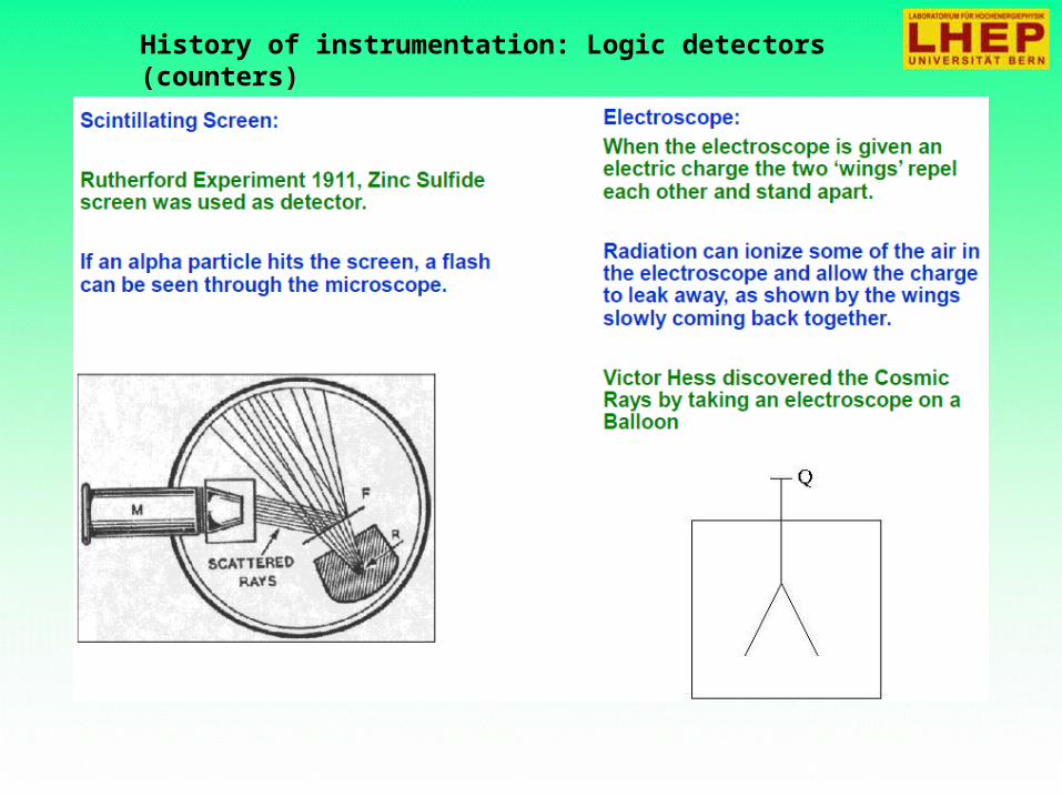
History of instrumentation: Logic detectors (counters)
First use of Coincidence

History of instrumentation: Logic detectors (counters)
Electronic coincidence circuit
History of instrumentation: Logic detectors (counters)

History of instrumentation: Logic detectors (counters)

History of instrumentation: Logic detectors (counters)

Ionization of Gases
Primary ionization Total ionization
Fast charged particles ionize atoms of gas.Often resulting primary electron will have enough kinetic energy to ionize other atoms.
primarytotal
iitotal
nn
W
xdxdE
W
En
43
ntotal - number of createdelectron-ion pairs
E = total energy loss
Wi = effective <energy loss>/pair
Lohse and Witzeling, Instrumentation In High
Energy Physics, World Scientific,1992
Number of primary electron/ion pairs infrequently used gases for MIP.
Wi - NOT the ionisation potential !!!

Ionization of Gases
Example: Ar
Density ~ 1.7 g/l
E = 1.8 MeV/(g/cm2) ~ 3 keV/cm
Wi = 26 eV/ion
ntotal ~ 100 ions/cm (~25 primary)

Ionization of Gases: first approximation
• The number of primary electron/ion pairs is approximately Poisson distributed.
!)(
m
enmP
nm
The detection efficiency is therefore limited to :
neP 1)0(1det
For thin layers det can be significantly lower than 1.For example for 1 mm layer of Ar nprimary= 2.5 → det = 0.92 .
Variation of the number of electron/pairs:
NOT exactly correct!
iLN
Ln
;nn
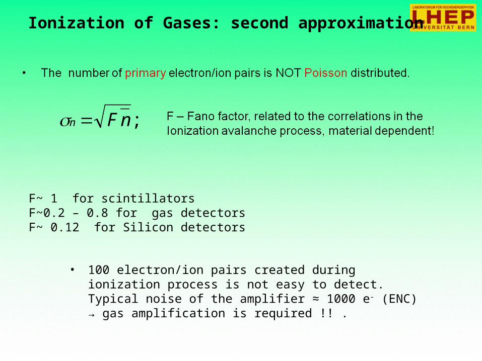
Ionization of Gases: second approximation
;nFn
F~ 1 for scintillators F~0.2 – 0.8 for gas detectorsF~ 0.12 for Silicon detectors
• 100 electron/ion pairs created during ionization process is not easy to detect.Typical noise of the amplifier ≈ 1000 e- (ENC) → gas amplification is required !! .

I-
Capacitor with gas at low electric field
Response to a primary ionization
Particle
Ar+ e-
Ar+ e-
E
Recombination losses q0=A*Q0
Primary ionisation Q0
e-
Attachment
losses q=q0e -(D/λ)
D, drift distance
I-
I-
+V
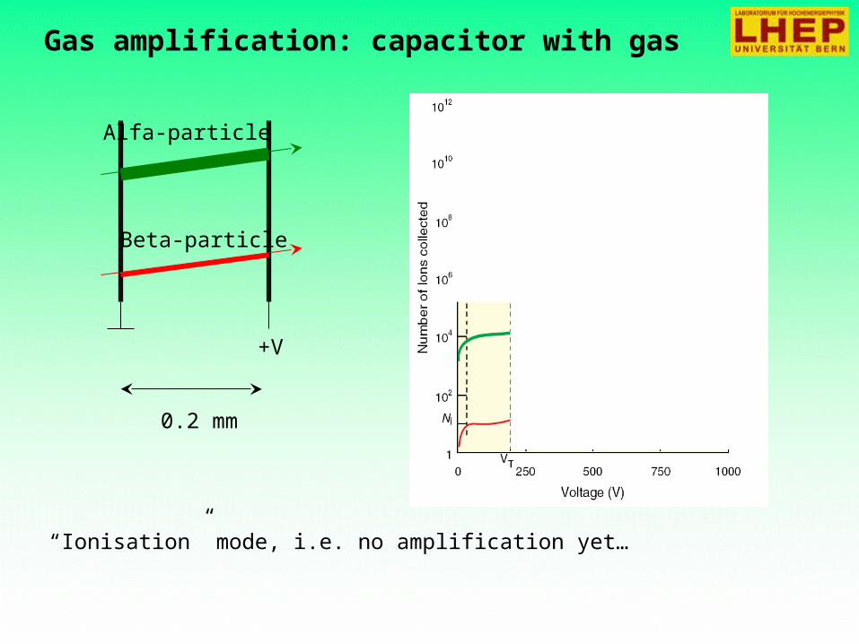
Gas amplification: capacitor with gas
Alfa-particle
Beta-particle
+V
0.2 mm
“Ionisation” mode, i.e. no amplification yet…

Gas amplification: capacitor with gas
+V
0.2 mm
“Proportional” mode, linear amplification…
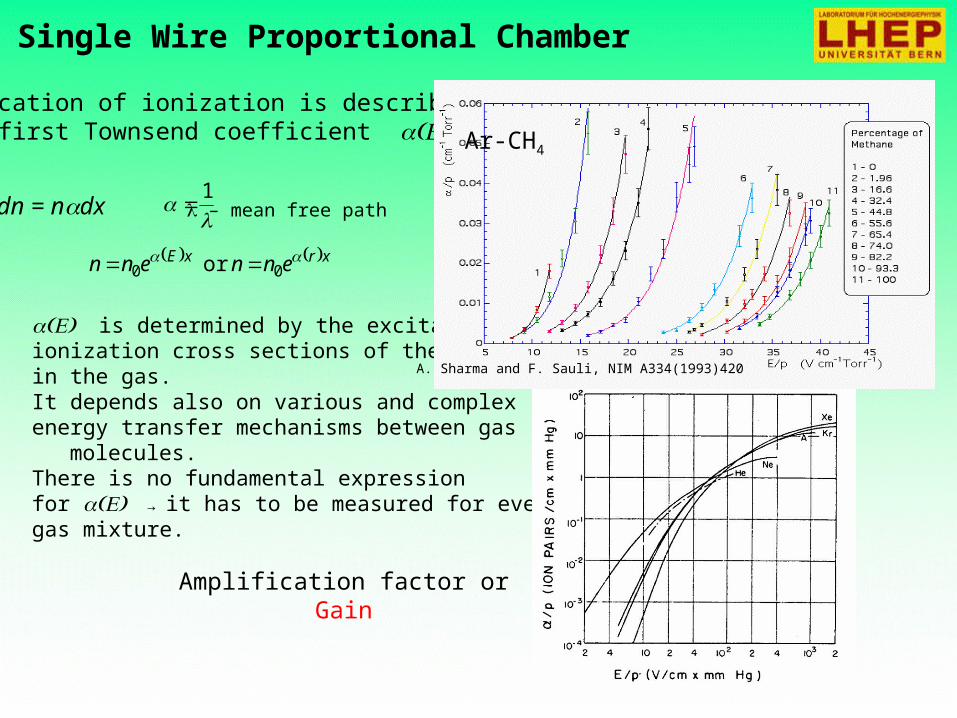
Single Wire Proportional Chamber
xrxE ennenn 00 or
1
Multiplication of ionization is described by the first Townsend coefficient
dn = ndx – mean free path
is determined by the excitation and ionization cross sections of the electrons in the gas. It depends also on various and complex energy transfer mechanisms between gas molecules.There is no fundamental expression for → it has to be measured for every gas mixture.
Amplification factor orGain
Ar-CH4
A. Sharma and F. Sauli, NIM A334(1993)420

Photoemission
In the avalanche process molecules of thegas can be brought to excited states.
Ar *11.6 eV
Cu
e-
cathode
De-excitation of noble gasesonly via emission of photons;e.g. 11.6 eV for Ar.This is above ionizationthreshold of metals;e.g. Cu 7.7 eV.
When gain exceeds about 108 - new avalanches → increase of the discharge current

Gas amplification: capacitor with gas
+V
0.2 mm
“Saturated” mode, logarithmic amplification, saturation…
Photoemission starts…
γ

Gas amplification: capacitor with gas
+V
0.2 mm
“Geiger” mode, only counting is possible, info about primary ionization is lost!
Strong photoemission…
γ

Gas amplification: capacitor with gas
+V
0.2 mm
“Saturated” mode, logarithmic amplification, saturation…
Strong photoemission, ion impact ionisation…
γ
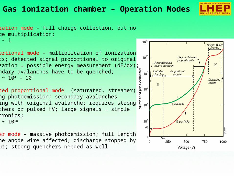
Gas ionization chamber – Operation Modes
• ionization mode – full charge collection, but nocharge multiplication;gain ~ 1
• proportional mode – multiplication of ionizationstarts; detected signal proportional to original ionization → possible energy measurement (dE/dx);secondary avalanches have to be quenched;gain ~ 104 – 105
• limited proportional mode (saturated, streamer) –strong photoemission; secondary avalanches merging with original avalanche; requires strongquenchers or pulsed HV; large signals → simple electronics;gain ~ 1010
• Geiger mode – massive photoemission; full lengthof the anode wire affected; discharge stopped byHV cut; strong quenchers needed as well

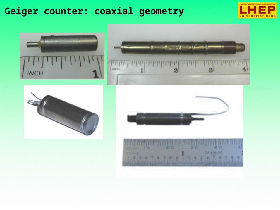
Geiger counter: coaxial geometry
Electrons liberated by ionization drift towardsthe anode wire.
Electrical field close to the wire (typical wire Ø~few tens of m) is sufficiently high for Geiger
mode discharge.
a
rCVrV
r
CVrE
ln2
)(
1
2
0
0
0
0
C – capacitance/unit length
R~1-10MOhm pulse Discharge is quenched
by the current-limiting resistor
Geiger counter: coaxial geometry
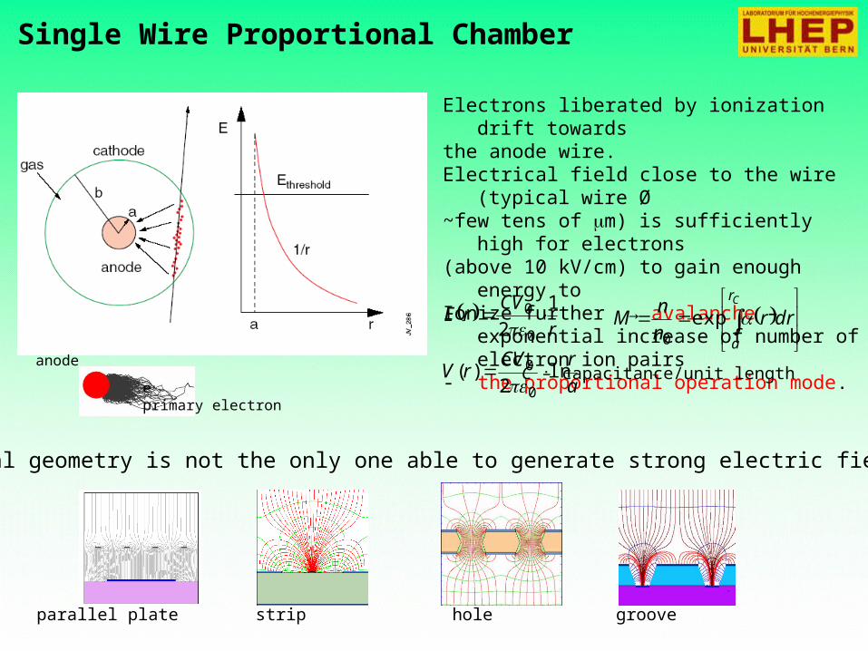
Single Wire Proportional Chamber
Electrons liberated by ionization drift towardsthe anode wire. Electrical field close to the wire (typical wire Ø~few tens of m) is sufficiently high for electrons(above 10 kV/cm) to gain enough energy to Ionize further → avalanche – exponential
increase of number of electron ion pairs- the proportional operation mode.
Cylindrical geometry is not the only one able to generate strong electric field:
parallel plate strip hole groove
a
rCVrV
r
CVrE
ln2
)(
1
2
0
0
0
0
C – capacitance/unit lengthanode
e- primary electron
Cr
a
drrn
nM exp
0

SWPC – Choice of Gas
In the avalanche process molecules of thegas can be brought to excited states.
Ar *11.6 eV
Cu
e-
cathode
De-excitation of noble gasesonly via emission of photons;e.g. 11.6 eV for Ar.This is above ionizationthreshold of metals;e.g. Cu 7.7 eV.
new avalanches → permanent discharges
Solution: addition of polyatomic gas as aquencher
Absorption of photons in a large energy range (many vibrational and rotationalenergy levels).
Energy dissipation by collisions ordissociation into smaller molecules.
ELASTIC IONIZATION
SUM OF EXCITATION
ELASTIC
IONIZATION
excitation levels
vibrational levels
S. Biagi, NIM A421 (1999) 234
S. Biagi, NIM A421 (1999) 234

SWPC – Signal Formation
drdr
dV
lCV
Qdv
0
Avalanche formation within a fewwire radii and within t < 1 ns.Signal induction both on anode andcathode due to moving charges(both electrons and ions).
Electrons collected by the anode wire i.e. dr isvery small (few m) – almost no induction signal
Ions have to drift back to cathode i.e. dr is large(few mm). Signal duration limited by total ion drifttime.
Need electronic signal differentiation to limit dead time.t (ns)
0 100 200 300 400 500
v(t)
300 ns
100 ns
50 ns
+
-
+
- +
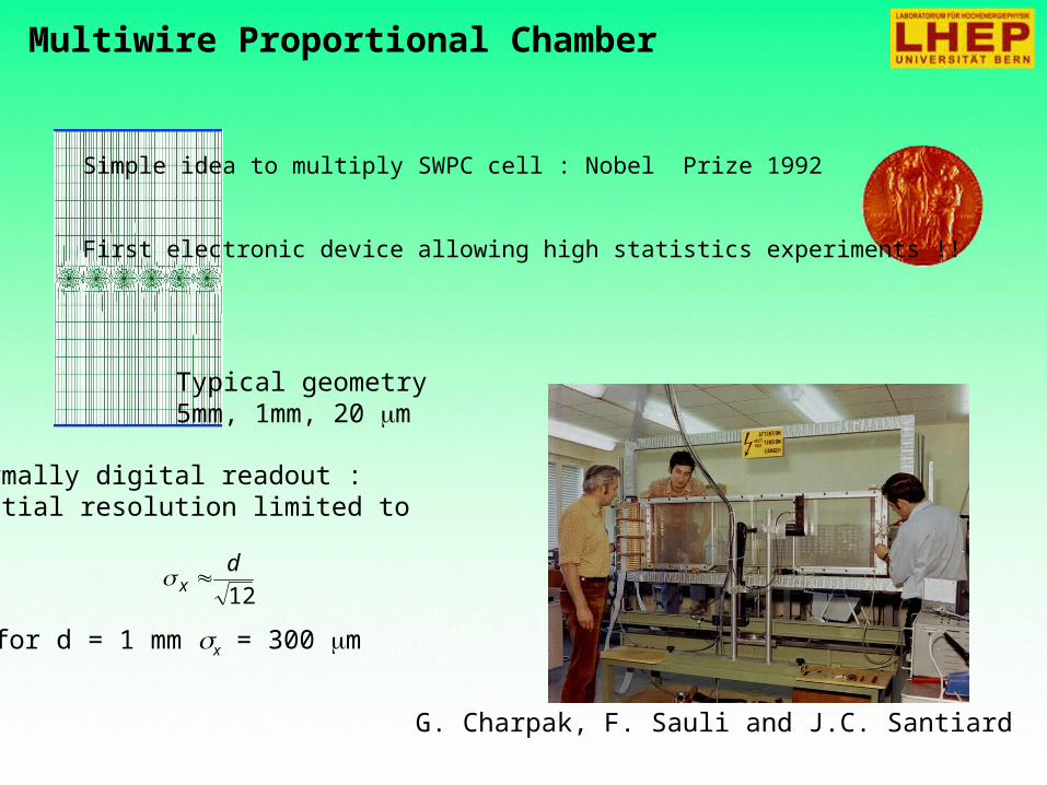
Multiwire Proportional Chamber
Simple idea to multiply SWPC cell : Nobel Prize 1992
First electronic device allowing high statistics experiments !!
Normally digital readout :spatial resolution limited to
12
dx
for d = 1 mm x = 300 m
Typical geometry5mm, 1mm, 20 m
G. Charpak, F. Sauli and J.C. Santiard
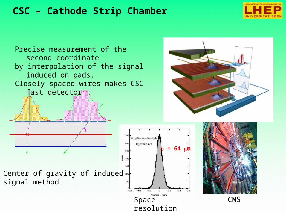
CSC – Cathode Strip Chamber
Precise measurement of the second coordinate
by interpolation of the signal induced on pads.
Closely spaced wires makes CSC fast detector.
Space resolution
CMS
= 64 m
Center of gravity of inducedsignal method.

RPC – Resistive Plate Chamber
Ec luste rs
resistive electrode
resistive electrode
gas gap
HV
GND
readout strips
readout strips
HV
GND
MRPC
Multigap RPC - exceptional time resolutionsuited for the trigger applications
Rate capability strong function of the resistivityof electrodes in streamer mode.
useful gap
= 77 ps
Time resolution
2 mm
A. Akindinov et al., NIM A456(2000)16

Limitations of Gas Detectors
Avalanche region → plasma formation (complicated plasma chemistry)
•Dissociation of detector gas and pollutants•Highly active radicals formation•Polymerization (organic quenchers)•Insulating deposits on anodes and cathodes
Classical ageing
Anode: increase of the wirediameter, reduced and variablefield, variable gain and energyresolution.
Cathode: formation of strongdipoles, field emmision andmicrodischarges (Malter effect).
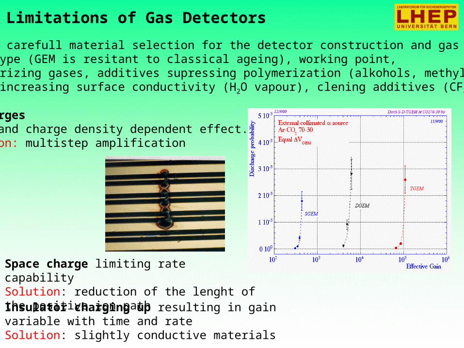
Limitations of Gas Detectors
DischargesField and charge density dependent effect.Solution: multistep amplification
Insulator charging up resulting in gain variable with time and rateSolution: slightly conductive materials
Space charge limiting rate capabilitySolution: reduction of the lenght of the positive ion path
Solutions: carefull material selection for the detector construction and gas system,detector type (GEM is resitant to classical ageing), working point,non-polymerizing gases, additives supressing polymerization (alkohols, methylal),additives increasing surface conductivity (H2O vapour), clening additives (CF4).

Computer Simulations
MAXWELL (Ansoft) electrical field maps in 2D& 3D, finite element calculation for arbitrary electrodes &
dielectrics
HEED (I.Smirnov)energy loss, ionization
MAGBOLTZ (S.Biagi) electron transport properties: drift, diffusion, multiplication, attachment
Garfield (R.Veenhof) fields, drift properties, signals (interfaced to programs above)
PSpice (Cadence D.S.) electronic signal

In the next lecture
Spark chamber
Gas Electron Multiplier
Drift tubes
Time Projection Chamber