Embed Size (px)
Citation preview

DETECTING ARCHITECTURAL MISMATCHESDURING SYSTEMS COMPOSITION
by
Cristina Gacek
--------
A Dissertation Presented to the
FACULTY OF THE GRADUATE SCHOOL
UNIVERSITY OF SOUTHERN CALIFORNIA
In Partial Fulfillment of the
Requirements for the Degree
DOCTOR OF PHILOSOPHY
(Computer Science)
December 1998
Copyright 1998 Cristina Gacek

ii
To Beba, Cacho and Nauro

iii
Acknowledgments
The end of the tunnel is actually here! Now is the time to start the next stage,
and I would like to do so by first recognizing the people that made the difference through-
out my Ph.D. study years.
First and foremost I must thank Nauro, my better half, for always being there,
making it all possible and worthwhile. This whole process has brought us even closer.
Both of our families deserve recognition for caring, cheering, and trying to understand the
various stages involved.
Barry Boehm, my advisor, has been a very special person to me. Not only has
he supported me throughout the years, mentoring me when I needed, but he has also been
a good friend. I deeply appreciate that.
My committee members Dave Wile and Eb Rechtin must also be acknowl-
edged. I must thank Dave for his deep involvement, actually bringing up new ideas and
helping me evolve them, as well as for the occasional pub stops during various workshops.
Dr. Rechtin was probably the most involved and knowledgeable outside committee mem-
ber in history. He not only devoted his time to reading the material I gave him, but always
had pertinent and intelligent comments to make.
Tony Wasserman has been an inspiration to me. His eagerness to help and
timely mentoring are admirable. Both he and Barry Boehm have taught me a lot about pro-
fessional posture and inter-personal relations. I wish more people were like them.
I will also have nice memories of Judy Kerner, Frank Belz and Andrew Landis-
man. They were always willing to hear my sorrows and had a friendly word of support.

iv
Last but not least come my friends. Many have come and gone during my stud-
ies at USC, but they were all important. I will certainly miss our technical discussions, as
well as the chats about politics, movies, various cultures, the weather, and anything imag-
inable. I will also miss our hiking events, climbing outings, workouts, going to the beach,
phone conversations, and simply sitting in the sun to warm up a bit. I refuse to list their
names here in fear of forgetting an important one, but I am sure they know who they are.

v
Table of Contents
Part I: Introduction.........................................................................................................1
1.0 Introduction..........................................................................................................2
Part II: Related Work......................................................................................................9
2.0 Related Work .......................................................................................................102.1 COMPLEMENT............................................................................................................ 10
2.2 Shaw and Clements........................................................................................................ 12
2.3 Kazman, Clements, Abowd, and Bass ........................................................................... 14
2.4 Stiger and Gamble.......................................................................................................... 19
2.5 Abd-Allah ...................................................................................................................... 19
2.6 Architecture Description Languages (ADLs) ................................................................ 262.6.1 ACME.............................................................................................................. 272.6.2 Aesop............................................................................................................... 282.6.3 C2 .................................................................................................................... 302.6.4 Darwin ............................................................................................................. 312.6.5 MetaH.............................................................................................................. 322.6.6 Rapide.............................................................................................................. 332.6.7 SADL............................................................................................................... 352.6.8 UniCon ............................................................................................................ 382.6.9 Wright.............................................................................................................. 40
Part III: Contribution .....................................................................................................42
3.0 Approach Description ..........................................................................................433.1 Extending the AAA Model ............................................................................................ 45
4.0 Styles Descriptions...............................................................................................484.1 Revisiting Event-Based.................................................................................................. 48
4.2 Blackboard ..................................................................................................................... 49
4.3 Rule-Based..................................................................................................................... 51
4.4 Logic Programming ....................................................................................................... 52
4.5 Transactional Database-Centric ..................................................................................... 53
4.6 Real-Time....................................................................................................................... 54
4.7 Closed-Loop Feedback Control ..................................................................................... 55
4.8 Internet Distributed Entities........................................................................................... 56
5.0 Conceptual Features.............................................................................................585.1 Descriptions ................................................................................................................... 58
5.1.1 Concurrency..................................................................................................... 585.1.2 Distribution...................................................................................................... 595.1.3 Dynamism........................................................................................................ 595.1.4 Encapsulation .................................................................................................. 605.1.5 Layering........................................................................................................... 605.1.6 Supported Data Transfers ................................................................................ 615.1.7 Triggering Capability ...................................................................................... 61

vi
5.1.8 Backtracking.................................................................................................... 625.1.9 Control Unit..................................................................................................... 635.1.10 Component Priorities....................................................................................... 635.1.11 Preemption....................................................................................................... 645.1.12 Reconfiguration ............................................................................................... 645.1.13 Reentrance ....................................................................................................... 655.1.14 Response Times............................................................................................... 66
5.2 Styles Choices................................................................................................................ 665.2.1 Distributed Processes....................................................................................... 675.2.2 Event-Based..................................................................................................... 675.2.3 Main-Subroutine.............................................................................................. 685.2.4 Pipe-and-Filter................................................................................................. 685.2.5 Transactional Database-Centric....................................................................... 695.2.6 Blackboard....................................................................................................... 695.2.7 Rule-Based ...................................................................................................... 705.2.8 Logic Programming......................................................................................... 705.2.9 Real-Time ........................................................................................................ 705.2.10 Closed-Loop Feedback Control....................................................................... 715.2.11 Internet Distributed Entities............................................................................. 715.2.12 Conceptual Features Table Revisited............................................................... 72
5.3 Conceptual Feature Space.............................................................................................. 72
6.0 Architectural Mismatches ....................................................................................786.1 Architectural Mismatches Examples ............................................................................. 78
6.2 Architectural Mismatches Table .................................................................................... 79
7.0 Modeling Styles and Their Features ....................................................................937.1 Basic Entities’ Model..................................................................................................... 93
7.2 Modeling the Conceptual Features ................................................................................ 98
7.3 Complete Model of Styles ............................................................................................. 1017.3.1 Pipe and Filter.................................................................................................. 1017.3.2 Main/Subroutine .............................................................................................. 1027.3.3 Distributed Processes....................................................................................... 1047.3.4 Event-Based..................................................................................................... 1057.3.5 Blackboard....................................................................................................... 1067.3.6 Database Centric.............................................................................................. 1087.3.7 Rule-Based ...................................................................................................... 1107.3.8 Logic-Programming ........................................................................................ 1127.3.9 Real Time ........................................................................................................ 1157.3.10 Closed Loop Feedback Control ....................................................................... 1167.3.11 Internet Distributed Entities............................................................................. 117
7.4 Modeling Composition and Mismatches Detection....................................................... 121
8.0 Compositional Mismatch Analysis ......................................................................1438.1 Abstraction on Paper...................................................................................................... 143
8.2 The AAA Model ............................................................................................................ 154
8.3 The AAA Tool ............................................................................................................... 1558.3.1 Miscellaneous .................................................................................................. 183
Part IV: Conclusion ........................................................................................................185

vii
9.0 Summary of Key Contributions ...........................................................................186
10.0 Future Directions .................................................................................................188
Part V: Bibliography and Appendices ............................................................................189
11.0 Bibliography ........................................................................................................190
12.0 Appendices...........................................................................................................195Appendix A: Introduction to the ZSL Notation.................................................195Appendix B: Abd-Allah’s Z Model...................................................................199Appendix C: Our Z Model ................................................................................224Appendix D: Time Related Classification of Systems and Operations .............292Appendix E: AAA Mismatch Analysis Results for Real-Time vs. All Other
Styles ......................................................................................................296Appendix F: Acronyms.....................................................................................386

viii

viii
List of Figures
Figure 1: Extending the Base Entities to Style-Specific Entities ............................21Figure 2: Mismatch #2 of Group Operation............................................................23Figure 3: Horizontal Composition Example............................................................37Figure 4: Data Flow Issues Axis .............................................................................76Figure 5: Control Flow Issues Axis.........................................................................76Figure 6: Organizational Issues Axis ......................................................................76Figure 7: AAA - Project Menu................................................................................155Figure 8: AAA - Project | New................................................................................156Figure 9: AAA - Artifacts Menu .............................................................................156Figure 11: AAA - NewName.....................................................................................156Figure 10: AAA - Styles’ List ...................................................................................157Figure 12: AAA - Style .............................................................................................158Figure 13: AAA - Subsystem ....................................................................................159Figure 14: AAA - Subsystem Backtracking..............................................................160Figure 15: AAA - Subsystem Component Priorities.................................................161Figure 16: AAA - Subsystem Concurrency...............................................................162Figure 17: AAA - Subsystem Control Unit...............................................................163Figure 31: AAA - Tools Menu ..................................................................................163Figure 18: AAA - Subsystem Distribution................................................................164Figure 19: AAA - Subsystem Dynamism..................................................................165Figure 20: AAA - Subsystem Encapsulation.............................................................166Figure 21: AAA - Subsystem Layering.....................................................................167Figure 22: AAA - Subsystem Preemption.................................................................168Figure 23: AAA - Subsystem Reconfiguration .........................................................169Figure 24: AAA - Subsystem Reentrance .................................................................170Figure 25: AAA - Subsystem Response Time...........................................................171Figure 26: AAA - Subsystem Supported Data Transfers ..........................................172Figure 27: AAA - Subsystem Triggering Capability.................................................173Figure 28: AAA - System..........................................................................................174Figure 29: AAA - System Subsystems......................................................................175Figure 30: AAA - System and Connections..............................................................176Figure 32: AAA - Mismatch Analysis.......................................................................177Figure 33: AAA - Mismatch Analysis Results..........................................................178Figure 34: AAA - Mismatch Analysis Results’ List .................................................183

ix

ix
List of Tables
Table 1: A Feature-Based Classification of Architectural Styles...........................14Table 2: Temporal Features of Architectural Elements .........................................16Table 3: Static Features of Architectural Elements................................................17Table 4: Four Instances in an Architectural Style Space .......................................23Table 5: Mismatches Related to the Conceptual Features .....................................24Table 6: Instances of Our Architectural Style Space .............................................73Table 7: Instances of Our Architectural Style Space (cont.)..................................74Table 8: Architectural Mismatches ........................................................................81Table 9: Real-Time and Internet Distributed Entities Styles’ Features..................145Table 10: RT and ID Systems’ Features ..................................................................146Table 11: Mismatches Related to the Call Bridging Connector ..............................147Table 12: Operation Invokes ....................................................................................293Table 13: Operation Followed_By...........................................................................293Table 14: Operation Interrupted_By ........................................................................294

x
Abstract
The USC Architect’s Automated Assistant (AAA) tool and method version 0.1
[Abd-Allah 1996] provides a capability for early detection of software architectural style
mismatches among four architectural styles: Main-Subroutine, Pipe-and-Filter, Event-
Based, and Distributed Processes. For these four styles, mismatch detection is based on a
set of seven conceptual features distinguishing each style, and a set of bridging connectors
characterizing compositions among the four styles. However, it was a significant open
question whether these conceptual features and connectors were sufficient to characterize
composition of other architectural styles.
The work presented here formalizes some additional architectural styles--
namely Blackboard, Closed-Loop Feedback Control, Logic Programming, Real-Time,
Rule-Based, Transactional Database, and Internet Distributed Entities styles--and extends
the mismatch analysis capability to cover interactions of the original four styles with the
new ones. The analysis results tested various hypotheses, such as the extensibility of the
conceptual feature framework for mismatch detection, and the sufficiency of the original
seven conceptual features to characterize the broader set of styles and their composition.
In our work we found that the underlying conceptual feature framework could
work to cover a broader range of styles and systems, with some extensions. However, the
conceptual feature set and the underlying Z-language formal model were not sufficient to
cover the full range of styles and systems interactions.
We have developed extensions to the conceptual feature set and Z formal
model to cover the full set of compositional interactions analyzed. Additionally, we pro-

xi
vide means for checking each and every mismatch at the model level, including the
dynamic ones, as well as a fully operational tool.
We also provide an initial discussion of a more formal basis for detecting and
classifying architectural conceptual features, thus providing a formal framework for
extending the models.

1
Part I: Introduction
In the following section, we present a description of the problem which this
work addresses, while discussing a few relevant concepts such as megaprogramming, soft-
ware architectures, and software architectural styles. We also give a short introduction to
Abd-Allah’s dissertation work [Abd-Allah 1996] that was used as the starting point for
this work, accompanied by brief comments on what this evolution effort entialed.
2
1.0 Introduction
Megaprogramming [Boehm and Scherlis 1992], the practice of software con-
struction in a component-oriented fashion heavily based on software components reuse,
has long been recognized as an important solution for the software crisis [McIlroy 1969]
[Radice and Phillips 1988]. It is a powerful means of not only reducing software develop-
ment costs in the long run, but also reducing the risk of project failure, improving software
quality, shortening development time, and greatly increasing the productivity of the indi-
vidual software developer.
One of the major elements that determine the success of an environment using
megaprogramming is the actual reuse of available software components with a minimum
amount of effort. This involves the software engineer determining the need for a compo-
nent that is already available, effectively selecting the component that does actually fulfill
his/her need, and appropriately using it. Some of the difficulties with past reuse attempts
have been in determining the amount of effort it takes to produce reusable components,
estimating the number of components to reuse, effectively selecting reusable components,
and adapting components originally thought completely reusable to subtle differences in
domain and/or architectural assumptions (about timing, synchronization, data forms, coor-
dinate systems, environment models, etc.). Facets were used to simplify the process of
selecting reusable components [Prieto-Diaz and Freeman 1987] [Gacek 1995], but still
underlying assumptions were ignored. Handling, or rather detecting, the differences in
underlying architectural assumptions is the focus of this work.

3
The Domain Specific Software Architecture (DSSA) approach was created
with the intention of providing an effective megaprogramming environment, where all
components contain the same underlying domain and architectural assumptions. “A DSSA
is a process and infrastructure that support the development of a Domain Model, Refer-
ence Requirements, and Reference Architecture for a family of applications within a par-
ticular problem domain. The expressed goal of a DSSA is to support the generation of
applications within a particular domain (also known as a product-line)” [Tracz 1994]. An
architecture in a specific domain will identify the domain’s conventions and shared
assumptions, the required degree of generality (number of parameters that can change)
and integrability (how a component fits within the context of the application). This
approach can be very successful, but it is not always feasible considering its very large up
front investment required for building the infrastructure.
Nowadays, in order to be competitive, a developer’s usage of Commercial off
the Shelf (COTS), or Government off the Shelf (GOTS), packages has become asine qua
non, at times being an explicit requirement from the customer. The idea of simplyplug-
ging together various COTS packages and/or other existing parts results from the mega-
programming principles. What people tend to underestimate are the side effects resulting
from the plugging or composition of these subsystems. Some COTS vendors tend to
preach that because their tool follows a specific standard, say CORBA, all composition
problems disappear. Well, it actually is not that simple. Side effects resulting from the
composition of subsystems are not just the result of different assumptions in communica-
tion methods by various subsystems, but the result from differences in various sorts of

4
assumptions, such as the number of threads that are to execute concurrently, or even on
the load imposed on certain resources. This problem is referred to as architectural mis-
matches [Garlan et al. 1995a][Abd-Allah 1996].
Some but not all of these architectural mismatches can be detected via domain
architecture characteristics, such as mismatches in additional domain interface types
(units, coordinate systems, frequencies), going beyond the general interface types in stan-
dards such as CORBA. Another significant source of architectural mismatches derives
from mismatches among architectural styles or sets of architectural features.
An architectural style defines a family of systems based on a common struc-
tural organization [Shaw and Garlan 1996]. It constrains both the design elements and the
formal relationships among the design elements [Perry and Wolf 1992].1 Some of these
constraints are common to various styles, for example having explicit data connectors to
support data transfers between components is not a characteristic only present in the pipe-
and-filter style, but it also occurs in the distributed processes one. The absence of these
constraints in other styles is just as important, e.g., the main-subroutine style does not
have explicit data connectors, but rather uses shared variables for data transfers by defini-
tion. A set of these special constraints was defined by Abd-Allah, and called the set of
conceptual features [Abd-Allah 1996].2 Different styles can then be characterized by
1. One can find various definitions of software architectures in the literature [Perry and Wolf 1992][Shaw and Garlan 1996] [Tracz 1994]. The one used throughout this work we introduced in aprevious paper [Gacek et al. 1995]. Namely, we consider an architecture to be a set of compo-nents, connectors, constraints imposed on the components, connectors, and their composition,and a supporting rationale. Such architectures should be presentable in various ways--differentviews supporting different needs.
2. Other classification efforts do exist, and are covered in the related work section (section 2.0 onpage 10).

5
selecting different options for each conceptual feature. That is, a style is defined by a set of
conceptual feature choices, where individually, each of those choices may also exist in
some other style.
Once a complete set of conceptual features is defined,1 we will be able to use
them to differentiate the various architectural styles and/or systems by concentrating on
these abstract characteristics. Abd-Allah’s work on conceptual features was based on the
distributed processes, event-based, layered, main-subroutine, multithreaded, pipe-and-fil-
ter, and software bus styles.2 Our work tested the hypothesis that his approach of using
conceptual features for mismatch detection was extensible to cover a broader set of mis-
matches, and that his set of conceptual features is sufficient to characterize other styles,
namely blackboard, closed-loop feedback control, logic programming, real-time, rule-
based, transactional database, and internet distributed entities styles (see section 3.0). We
also started working towards determining the various dimensions that could be used to
describe orthogonality of the various conceptual features, thus providing a more formal
description of the conceptual feature space (section 5.3).
When actually building systems, people may or may not adhere to a pure archi-
tectural style, also the same style name may mean slightly different things to different peo-
ple. For example, in some pipe-and-filter analyses, [Shaw and Garlan 1996] has found it
useful to employ the concepts of colored pipes and parametrized filters. In cases where
some variation of an existing style is used, a complete set of conceptual features should
1. It is not the aim of this work to generate a complete set of conceptual features, specially becausethere is no way of proving completeness here.
2. See section 2.5 on page 19 for a complete description of his work, as well as how it compares tothe work presented here.

6
suffice for description. Clearly, if some completely new style comes along, using some
revolutionary paradigm, the set of conceptual features needs to be revisited, and poten-
tially extended.
The use of COTS and GOTS packages brings a slightly different light into the
problem. Hardly ever will a COTS vendor be willing to explicitly describe all the intrin-
sics of their package to the general public. In such cases, the use of conceptual features
becomes a facilitator, since vendors may be willing to give out at least general information
on these characteristics--they do describe the system and often help describe API’s, with-
out giving away secrets that could reduce the vendor’s competitive advantage.
When composing systems, many potential architectural mismatches can be
detected by analyzing their various choices for conceptual features. Mismatches may
occur because the subsystems have different choices for some particular feature. For
example, one is multi-threaded and the other is not, creating the possibility of synchroni-
zation problems when accessing shared data (the single-threaded part assumes there is
absolutely no risk of interference). Mismatches may also occur because the subsystems
make the same choice for some particular feature. For example, if two subsystems are sin-
gle-threaded, we may also run into synchronization problems when accessing some shared
data, since both parts assume there can be no interference.
It is extremely important to point out that different architectural styles may
have different meanings to different people, as well as that occasionally there is a need to
use a slightly adapted style (non-pure), especially when describing a previously existing
system (either OTS or from a components’ library). Thus, by working at the conceptual

7
feature level for mismatch detection, we can cover a much wider range of systems’ com-
position than if we dealt with the problem in a style by style basis.
The aim of this dissertation is to formally address software composition at the
architectural level while detecting architectural mismatches. We chose to do so by
addressing a number of open questions in the previous work by Abd-Allah in order to get
a greater and more formal coverage of conceptual features, and their relations to architec-
tural mismatches. We specifically looked into his hypotheses that architectural mis-
matches are derivable from conceptual features, that his 16 mismatches were a
comprehensive set of mismatches that are detectable based on conceptual features, and
that his conceptual feature set should suffice for mismatch detection.
Succinctly, the problem examined is:
What is a formal model for detecting potential architectural mismatches dur-
ing the composition of software systems? Where must current formal models be
further structured and extended to cover mismatches among wider ranges of
architectural styles?
In order to address the questions above, we needed to understand the complex-
ities of systems composition and its potential side effects. It was also necessary to have a
firm grasp on the characteristics of a wide range of architectural styles, and their relevance
to composition. As a means of providing a model supporting the concepts uncovered, it
was also essential to have a deep understanding of the formalism to be used, and provide
some mechanism to analyzing given formal specifications.

8
As a result of our effort, we did show that Abd-Allah was correct in assuming
that using conceptual features for mismatch detection was an extensible framework,
though it did require a considerable amount of effort to do so. We also found that Abd-
Allah’s 16 mismatches were far from being a robust set of mismatches that are detectable
based on conceptual features. Furthermore, his assumption that his conceptual feature set
should suffice for mismatch detection was incorrect.
While aiming to provide the proper support required to address our central
problem, and strengthen Abd-Allah’s initial work we had to considerably evolve his con-
ceptual feature (section 5.0 on page 58) and mismatch sets (section 6.0 on page 78). Con-
sequently, we had to perform major changes to the AAA formal model he provided
(section 7.0 on page 93). Additionally, we incorporated in the model operations for explic-
itly detecting each and every one of the mismatches, including the dynamic ones
(section 7.4).1
One should note that this work not only provides a formal model to support
architectural composition, but a fully operational tool is also provided to automate this
compositional analysis (section 8.3 on page 155).
1. A more detailed description on how the AAA framework evolved is provided in section 3.1 onpage 45.

9
Part II: Related Work
Other researchers have been working on software architectures and their com-
position, architectural styles and their classification, and systems classification based on
conceptual features. The following section describes some of their results, and discusses
the deficiencies of these past efforts with respect to addressing the central question of this
dissertation. It also includes some discussion on various ADLs and their approach to com-
position of heterogeneous systems.

10
2.0 Related Work
There are several related works that should be discussed here. They cover top-
ics such as real-time systems classification while considering a different set of conceptual
features by the COMPLEMENT project (section 2.1), architectural styles and their classi-
fication by Shaw and Clements (section 2.2), architectural elements classification by
Kazman and his colleagues (section 2.3), Stiger and Gamble’s Z formal model of the
blackboard style (section 2.4), and Abd-Allah’s dissertation work on detecting architec-
tural mismatches during systems composition, while focusing on the main-subroutine,
pipe-and-filter, distributed processes, and event-based styles (section 2.5). Some architec-
ture description languages (ADLs) and their supporting tools are also discussed
(section 2.6).
2.1 COMPLEMENT
The COMPLEMENT project focuses on technical aspects of developing real-
time and embedded systems [Pyle et al. 1993]. In order to understand what particular fea-
tures make real-time and embedded systems different from other systems, and what differ-
entiates one kind of real-time and embedded system from another, they devised a domain
specific system taxonomy (where the domain is simply real-time and embedded).
Their taxonomy consists of sets of primary, secondary, and concrete features.
Their primary features are: concurrent processing (many or few concurrent events); hard-
ware interface (significant or not); timed reaction to events (hard or soft real-time1); distri-
bution (multiple or single site); and database (significant or not). Their secondary features

11
are: dependability (high or low); reconfigurability (on or off-line); usability--human/com-
puter interface (intuitive or need training); certifiability (essential or not required); con-
straints--environmental aspects (significant or not); and evolution capability (evolutionary
or not). Their concrete features are: target platform; type of external transducers; replica-
tion; contractual requirements; and application domain.
The COMPLEMENT project uses their system taxonomy as a real-time and
embedded systems classification facilitator, and not as the focus of compositional analysis.
Still the features they use can give us some insight on characteristics we may need to con-
sider for our compositional purposes.
At first glance, their set of primary and concrete features should be a part of the
issues considered for composition, whereas their secondary features, which are mainly
quality attributes are not as relevant. A closer look at their primary features reveals that
whereas having a significant hardware interface may change dramatically a system’s per-
formance (as opposed to one that has a more significant human interface), this characteris-
tic is outside the scope of this work. All other primary features are very relevant for
composition, and thus part of our conceptual features.1
Most of their secondary features, being quality attributes could be considered
here, but actually go beyond what this work is addressing. The only one that is useful to
include is the one indicating whether a system is reconfigurable on or off-line. During
1. Hard real-time requirements are those that if the system reacts too late, it is considered to fail.On the other hand, soft real-time requirements are those that it is undesirable that the systemreacts too late, but it is not considered a failure if it happens.
1. Note that in our case, timed reaction to events may take the values predictable, bounded,unbounded, and cyclic, as well as unconstrained.

12
composition, if one of the subsystems expects to be able to reconfigure on-line while the
other does not, we might run into problems.
From their set of concrete features, two do not apply here, namely contractual
requirements and application domain. During composition, one would only consider an
existing system to be reused if it was known to conform to the contractual requirements at
hand, be them on programming language, standards or any other. As far as application
domain goes, the only difference this could bring to a composition consideration is on the
quality attributes originally required of the sub-system. As already mentioned above, on
the discussion of the secondary features, quality attributes and their detection at the archi-
tecture level are very important, but go beyond the focus of this work.
2.2 Shaw and Clements
Shaw and Clements present a classification of architectural styles based on a
set offeatures focusing on control and data issues. They do this by describing feature cat-
egories, and defining how each of several styles handles them. They also provide a few
rules of thumb to aid on style selection when implementing solutions to specific problem
instances [Shaw and Clements 1997].
The architectural style classification they propose is based on: the kinds of
components and connectors that are used; how control is shared, allocated, and transferred
within the system; how data is communicated through the system; how data and control
interact; and the type of reasoning that is compatible with the style. As control issues they
address the topology, synchronicity, and the binding time. Data issues include topology,

13
continuity (how continuous is the flow of data throughout the system?), mode (how is data
made available throughout the system?), and binding time. Control/data interaction issues
elaborated are whether control and data flow topologies have similar shapes or not, and if
these shapes are the same, whether control and data flow in the same or opposite direc-
tions.
They present their results in terms of a table. Their full classification can be
found on their paper. In table 1 one can find some examples of their classification that can
already be compared with results obtained by Abd-Allah (section 2.5), and by the work
described in this document (section 5.0 on page 58).
The granularity level of the features considered by Shaw and Clements is lower
than the one to be used by this work to classify systems. The information they convey for
classification purposes is part of our underlying model, but it is not considered at the con-
ceptual features (more abstract) level. Exceptions are the fact that the model described in
this document does not include information on types of reasoning supported by the style,
nor information on control or data binding time. Mode of data transfers is the only one of
their features that shows as a conceptual feature in our work.
The focus of their paper is to classify styles while standardizing the vocabulary
and concepts each involves, and discriminate among styles showing their differences and
similarities, supporting for the organization of advice on how to select a style for solving a

14
specific problem. Since it is not part of their focus, they do not address compositional
issues.
2.3 Kazman, Clements, Abowd, and Bass
In a recent work [Kazman et al. 1997], related to that of Shaw and Clements
(section 2.2), Kazman and his colleagues try to support system composition in a manner
very similar to the one used here. They use behavioral characteristics which they callfea-
Main program/subroutine
Event systems Blackboard
Components procedures, data processes memory,computations
Connectors procedure calls implicit invocation direct access
Control topology hierarchical arbitrary star
Synchronicity sequential asynchronous,opportunistic
asynchronous,opportunistic
Control bindingtime
write, compile invocation, run write
Data topology arbitrary arbitrary star
Continuity sporadic,low-volume
sporadic,low-volume
sporadic,low-volume
Mode passed, shared broadcast passed
Data binding time write, compile, run invocation, run write, compile, run
Isomorphic con-trol/data shapes
no no yes
Control/data flowdirections
n/a n/a opposite
Type of reasoning hierarchical (localreasoning)
nondeterminism ---
Table 1: A Feature-Based Classification of Architectural Styles

15
tures to classify architectural elements (components and connectors), not architectural
styles nor systems. The behavioral characteristics they considered useful are temporal and
static ones.
A temporal view of architectural elements describes the behavior of an element
over time. The temporal characteristics they address are: times of control acceptance;
times of data acceptance; times of control and data transmission; if forks occur; and
whether the element retains state information.
A static view of architectural elements summarizes their invariants. The static
characteristics they address are: what the data and control scopes are; whether the element
transforms data; binding time; if connecting to this element blocks the connecting ele-
ment, does the element relinquish control; are ports in, out, or in/out; and how many ele-
ments can connect to each port, both at any one moment in time, and over the lifetime of
the element.
They give examples of architectural elements classifications. A subset of those
can be found below; only those that would be relevant for main-subroutine and blackboard
systems are introduced.
By examining their temporal features (table 2), one can see that some of them
were already part of the AAA model and the conceptual feature set (e.g., “forks?”), others
are included in our work (e.g., “accepts control at other than ts?” see section 5.0 on
page 58).
Their static features are a bit different (table 3), most of these are part of our
model, but not all are part of the conceptual features set, the reason being that they are in a

16
lower level of detail than what we consider applicable for our conceptual features. Ports
information, for example, is part of the model, but does not show up in the conceptual fea-
tures set. Control scope and relinquishing control (we have it under response time as
cyclic) do show at both our model and conceptual features level (section 5.0 on page 58).
Information on whether data is transformed or not is not part of our model, nor our con-
ceptual features set.
There are also some conceptual features that we have found extremely relevant
for composition, that are not included in their set of features, some of them are whether
there is backtracking allowed, whether components have priorities associated with them,
Accepts controlat otherthan ts?
Trans-mits
controlat otherthan te?
Forks? Retainsstate?
Single-entryproce-dure
never never always never not cri-terial
not cri-terial
never samethread
Object never never always never not cri-terial
not cri-terial
never sameor dif-ferent
threads
Function never never always never always not cri-terial
never samethread
Proce-dure call
never never always never always never never samethread
Black-board
always always not cri-terial
always not cri-terial
always never sameor dif-ferent
threads
Table 2: Temporal Features of Architectural Elements
Accepts data
At ts?At otherthan ts?
Transmits data
At te?At otherthan te?
TemporalFeatures
Arch.Element

17
and whether there is preemption or not. These features were not part of the original AAA
model, but have been added by this work (section 5.0 on page 58).
Kazman and his colleagues also discuss composition of architectural elements.
They mention that when composing two elements some of their features must match,
whereas others can be ignored. As features that must match they mention ports and their
associations. As features that may be ignored they list state retention, data transformation,
blocks, forks, and relinquish. They do not provide a formal discussion on the feature com-
binations of composing elements that are allowed or not, and the compositional discussion
they provide is only of a one element plus another approach (i.e., they don’t discuss prob-
lems at the system level).
Datascope
Con-trol
scope
Transforms data?
Bindingtime
Blocks?
Relinquish
?
Ports
Single-entry pro-cedure
virtualaddress
virtualaddress
yes spec.,execu-tion
notcrite-rial
yes 1 I;m O
1 n
Object virtualaddress
virtualaddress
yes spec.,execu-tion
notcrite-rial
yes n I;m O
1 n
Function virtualaddress
virtualaddress
yes spec.,execu-tion
notcrite-rial
yes 1 I;m O
1 n
Procedurecall
virtualaddress
virtualaddress
no spec. yes yes I;O
1 1
Blackboard distrib-uted
distrib-uted
no spec.,invoca-
tion,execu-tion
notcrite-rial
yes I;O
1 n
Table 3: Static Features of Architectural Elements
Associations
Perconn
Lifetime
StaticFeatures
Arch.Element
18
The major difference between their classification and the one being offered
here is that they are doing so at the element (component and connector) level, whereas we
do it at the system level (percolating to the architectural element level in the model). This
means that our classification is a little more abstract than theirs, hence probably more
applicable at earlier stages than theirs. Also, they do not offer clear guidelines on how to
use their set of features during system composition, nor do they allow for analysis of the
composition of several elements together. Which means that as long as the elements agree
on a one-to-one basis, they detect no problems. Well, here are a few examples of possible
problems:
• A blocking data connector connecting control components A and B (3 ele-
ments). If control component B does not become (or is not) active after A sends
some data, A will be in a deadlock situation.
• Two control components in the same thread sharing a blocking data connector
(3 elements), creates a possibility of deadlock.
• A call to a cyclic (or non-control relinquishing) component, will leave the caller
in a deadlock.
Note that the last example also contradicts their assumption that whether an element relin-
quishes control or not is irrelevant for composition.
Summarizing, they offer a very good classification framework for architectural
elements, and weaker ways of detecting element to element mismatches. They do not pro-
vide a framework for composing system architectures, nor insights on possible architec-
tural mismatches during the composition of systems.

19
2.4 Stiger and Gamble
Stiger and Gamble present a formal model of a blackboard style [Stiger and
Gamble 1997]. They use Z to specify the relevant elements such as components, connec-
tors, and configurations. Just like the work by Abd-Allah (section 2.5), their Z specifica-
tion is unable to handle dynamic information.
Additionally they claim that “the knowledge source component can be refined
to any embedded architectural style allowing the blackboard architecture to pose as an
integration architecture,” but no proofs, examples or explanations on what was meant is
provided. Even if this claim was to be proven correct, the approach could potentially avoid
some architectural mismatches (the same kind covered by CORBA for example), but still
mismatches related to backtracking, resource contention, and response time among others
could occur.
2.5 Abd-Allah
Abd-Allah’s work on his dissertation and the Architect’s Automated Assistant
(AAA) [Abd-Allah 1996] tackled a portion of the problem this thesis is focusing on. He
constructed a model and a prototype tool to detect potential architectural mismatches dur-
ing systems composition, while focusing on the main-subroutine, pipe-and-filter, distrib-
uted processes, and event-based styles. He modeled styles and systems using Z [Spivey
1992]. His complete Z model can be found in appendix B.

20
Abd-Allah described some base elements that can be refined and combined in
various ways in order to describe architectural styles and/or specific systems (see figure 1).
These base elements are:
1. A port is typically associated with a control component, and isthe latter’s entry and exit points for data during data transfers.
2. A data component models data that is used to store state or istransferred across data connectors.
3. Acontrol component models data that is executed by the under-lying machine and which can initiate (and respond to) data andcontrol transfers. It is assumed to have a single thread of control(from a hardware point of view, a control component has a singleprogram counter).
4. Anobject is an encapsulation of a set of data components with aset of control components. Not only from a formal standpoint is anobject fundamentally different from a data or control component(i.e. {X} is not the same type as X), but there are other reasons forthis distinction,
• an object can include complex interconnections within itself,forming its own single-threaded minisystem (see the definitionof system below)
• an object can be instantiated many times, each time introduc-ing a new set of different data and control component copies
5. A data connector models the potential for two or more controlcomponents or objects to engage in data transfers amongst them-selves.
6. Acontrol connector models the potential for two or more controlcomponents to engage in control transfers (possibly with data)amongst themselves.
7. A trigger associates an action (a data or control transfer) withthe reception of a data component by a control component orobject.
8. A system is a non-empty set of interconnected control compo-nents or objects satisfying some unique purpose.

21
Abd-Allah also suggested the use of conceptual features as a higher level
abstraction for describing architectural styles and/or systems characteristics (see also
section 1.0). The conceptual features he used were:
1. Dynamism. Earlier we discussed how the topology of softwarecan be dynamic, adding and removing concurrent threads as it exe-cutes. Some styles constrain the topology to be static (i.e. the num-ber of concurrent threads remains constant), while other styles donot. A style is dynamic if and only if it allows non-blocking controlconnectors (spawns).
2. Supported data transfers. Of the styles we studied, all of themachieved data transfers through one (or more) of three mechanisms:explicit data connectors, an implicit global network of data connec-tors, or shared data variables.
“Thing”
Data Control Object Data ControlPort
Data store Procedure
ProcessFilter
Object
Socket
Event queue
Shareddata
Pipe Circuit
Call Spawn
Pipe & Filter Style
LexicalAnalyzer
SyntaxParser
SemanticAnalyzer
CodeGeneratorCompiler:
Component Component Connector Connector
Figure 1: Extending the Base Entities to Style-Specific Entities

22
3. Triggering capability. Hardware has interrupts, and softwarehas triggers. Some styles allow the transfer of data (events) alongexplicit data connectors or a global network to cause certainactions, e.g. control transfers or additional data transfers.
4. Concurrency. Styles often constrain the number of concurrentthreads that may execute within a system. A single-threaded systemis limited to only one thread of control components linked by achain of calls (blocking control connectors), while multi-threadedsystems allow more than one thread to execute concurrently. Notethat concurrency is not the same as dynamism.
5. Distribution. A style may or may not constrain the mapping ofsystem entities to nodes. If the mapping is to more than one node,then the style’s systems are naturally distributed.
6. Layering. Styles may or may not impose system layering con-straints on its control components. The layers must be specifiedwith respect to a connector, e.g. a set of layers linked by controlconnectors.
7. Encapsulation. As shown earlier, objects are fundamentally dif-ferent from data control components. A style may choose to beobject-oriented or not.
How each of these features applies to each of the styles he discussed is shown
in table 4. Conceptual features get propagated into the Z model as a set of constraints on
the base elements that varies from style to style, depending on the choices made for each
of the conceptual features.
He then continued to show how the combination of the presence and/or
absence of certain conceptual features on parts to be composed could potentially cause
architectural mismatches, depending on thebridging connector1 used between them.
These are described in table 5.
1. Bridging connector is the term he uses to refer to the connector used to compose the partstogether. We also use this term for the same purpose.

23
An explanation of each mismatch is given below.
1. Two concurrent threads share data, with potential synchroniza-tion problems.
2. Two threads have data connectors to 2 different control compo-nents in a third thread (it is impossible for the third thread to exe-cute in the two components simultaneously - see figure 2).
Pipe & FilterMain/
SubroutineDistributedProcesses
Event-Based
Dynamism static static dynamic static
Supported datatransfers
explicit dataconnectors
shared datavariables
explicit dataconnectors
implicitnetwork,
shared datavariables
Triggeringcapability
no N/A no yes
Concurrencymulti-
threadedsingle-
threadedmulti-
threadedsingle-
threaded
Distribution unconstrained single nodemultiplenodes
unconstrained
Layering unconstrained unconstrained unconstrained unconstrained
Encapsulation no no no yes
Table 4: Four Instances in an Architectural Style Space
control component
thread 1 thread 2 thread 3
call
data connector
Figure 2: Mismatch #2 of Group Operation

24
3. Two control components in the same thread share a blockingdata connector, creating a possibility of deadlock.
4. A layering constraint is violated.
5. Different sets of recognized messages are used by two subsystemsthat permit triggers.
6. A spawn is made into a subsystem which originally forbade them.
7. An unrecognized trigger message is used.
8. A triggered spawn is made into a subsystem which originally for-bade spawns.
9. A trigger refers to a subsystem which originally forbade trigger-ing.
10. A data connector is made into a subsystem which originally for-bade them.
11. A shared data relationship refers to a subsystem which origi-nally forbade them.
12. A trigger refers to a subsystem which forbids explicit or implicitdata connectors, hence the trigger may never occur.
Dyn
amis
m
Dat
a Tr
ansf
ers
Trig
gere
d
Con
curr
ency
Dis
trib
utio
n
Laye
ring
Enc
apsu
latio
n
call 15 4
spawn 6 13 15 4
data connector 10 2,3 15 4
shared data 11 1 15
triggered call 12 5,7,9 15 4
triggered spawn 8 12 5,7,9 14 15 4
triggered data trans-fer
12 5,7,9 15 4
shared machine 16
Table 5: Mismatches Related to the Conceptual Features

25
13. A spawn is made into a subsystem which is not concurrent.
14. A triggered spawn is made into a subsystem which is not con-current.
15. A remote connector is extended into or out of a non-distributedsubsystem (i.e. a subsystem originally confined to a single node).
16. A node resource is overused (this is actually checked by sum-ming across the subsystems’ usage of that particular resource).
We found the framework he used for basing mismatches detection on concep-
tual feature choices to be useful for dealing with a broader set of styles and systems, as
long as we extended it accordingly.
His investigation of the above mentioned styles yielded him with a set of 7
conceptual features (see above) and 16 detectable mismatches. Our work based on a
broader set of styles (section 4.0 on page 48) has proven his conceptual feature and detect-
able mismatches set to be quite insufficient (section 5.0 on page 58, and section 6.0 on
page 78, respectively).
In order to investigate other styles such as blackboard and real-time, we
changed slightly his set of architectural base elements (e.g., trigger is not a base element
anymore, but actually a relation between sets of events and sets of actions), and their char-
acteristics on the underlying model (for example to include component priorities).
As far as his set of conceptual features are concerned, his model had a consid-
erable coverage for the styles he focused on, but certainly not for some other very com-
monly used styles such as real-time, and closed-loop feedback control for example.
Characteristics such as being a system preemptive, reentrant, and containing component

26
priorities or not are completely absent from his model, even though they are extremely rel-
evant for composition. Furthermore, he considered encapsulation one of his conceptual
features, but never showed it had any relevance to architectural mismatches during compo-
sition.
Additionally, he provided no clear guidelines for determining when to add new
conceptual features (i.e., which characteristics are to be considered or not, and why). He
provided no discussion on how the conceptual feature space was composed, ways of clas-
sifying it, and means of extending it. Issues that we do briefly discuss in section 5.3.
His Z model did not make use of Z operations on schemas that do actually alter
the schemas attributes contents. Consequently he was unable to provide for dynamic
checks on certain constraints that would actually allow for the detection of dynamic mis-
matches. We have added the operations StartSystem, ActualControlTransfer, and Actual-
DataTransfer that are able to do exactly that.
Besides, his work only provided a very limited prototype, whereas we have
built a working tool for mismatch detection.
2.6 Architecture Description Languages (ADLs)
Here one can find a discussion of several ADLs and their supporting tools,
while focusing on the problem of composition of heterogeneous systems. For a survey on
ADLs and their supporting tools in general, please refer to the work by Medvidovic [Med-
vidovic 1997].

27
It is important to note that the observations presented here are just a picture in
time. The tool set related to each and every ADL is continuously evolving, as are some of
the ADLs themselves (e.g.: ACME).
2.6.1 ACME
ACME is an architecture interchange language [Garlan et al. 1995b][Garlan et
al. 1997]. Rather than being yet another ADL, it is an interchange mechanism, intended to
support transformations of architectural specifica-
tions between heterogeneous ADLs. Consequently, ACME has no direct tool support,1 but
enables the use of support tools from various ADL suites.
The approach consists of providing means of describing the structural (or topo-
logical) characteristics of architectures, along with annotations containing ADL-specific
information. This strategy allows the sharing of common architectural information by var-
ious ADLs and their tools, as well as supports the specification of information not present
in all ADLs. “This is the essence of ACME. The language provides a fixed vocabulary (or
ontology) for representing architectural structure. Additionally it provides an open seman-
tic framework in which architectural structures can be annotated with ADL-specific prop-
erties. In this way ACME achieves the benefits of both an intersection and a union
language: the shared structural core represents an intersection of the expressive capabili-
1. ACME has no direct tool support, but it does enforce some structural constraints, such as disal-lowing a connector to be attached to another connector, or the existence of a dangling port.

28
ties of most ADLs, while the use of annotations accommodates the union of ADL-specific
concerns.” [Garlan et al. 1997]
In the context of this work, ACME could be applied in several ways:
• Specifications written in any arbitrary ADL and then translated into ACME
could then be translated into the formalism used here, permitting its use as input
for the analysis capability introduced here.
• This work could actually use ACME as its native modeling language, making
heavy use of annotations for semantic needs not covered by ACME.
• Specifications written using the formalism introduced here could be translated
into ACME, allowing for further analysis by other ADLs and their tools.
We chose not to use ACME as the native modeling language simply because the exten-
sions required would be so many that it would actually defeat the purpose of using a previ-
ously existing ADL. Importing descriptions to or form ACME could be addresses by
future work.
2.6.2 Aesop
Aesop is a tool kit designed to support the rapid development of “style-aware”
software architecture design environments. A style specific environment is achieved by
providing style-specific vocabulary of design elements (as subtypes of basic architectural
classes), stylistic constraints as methods of these types, and a collection of external tools
that perform architectural analyses that are relevant to that specific style [Garlan 1995].

29
The Aesop tool kit includes a repository for architectural level design elements
and patterns called the Software Shelf [Monroe and Garlan 1996]. The Software Shelf
supports the classification, storage, and retrieval of architectural elements, namely compo-
nents, connectors and configurations (or patterns). Design elements stored in this reposi-
tory are classified by category (component, connector or pattern), style or set of styles for
which it was created, and class within the style (i.e., type of component, connector, or pat-
tern within the particular style).
It is critical to note that Aesop focuses on homogeneous architectures, so envi-
ronments are specialized by style, not allowing the use of more than one style at a time.
Our work handles composition of both homogeneous and heterogeneous software systems
architectures.
It is also important to highlight that the reusable architectural elements pro-
vided by the Aesop Software Shelf are abstract or incomplete design fragments, to be fur-
ther refined upon retrieval. Even though the primary focus of one of their works is to
integrate software architecture, architectural styles, and software reuse [Monroe and Gar-
lan 1996], it is not in the scope of the Aesop tool kit to try to accommodate the architec-
ture of pre-existing software. Consequently, their focus is different from the one in our
work.
We can see one danger on trying to evolve the work in the Software Shelf to
also cover pre-existing software, namely that hardly ever will one be able to find some
OTS product whose architecture has been defined in one pure architectural style. Even
when addressing OTS components, if we have the developer of the component being the

30
one specifying the architecture style used, his/her definition of the style might be different
than that of the (re)user of the component.This would introduce some considerable com-
plexity on Software Shelf’s classification scheme, and consequently on the retrieval as
well.
2.6.3 C2
C2 and its design environment (Argo) support the description of user interface
systems using a message-based style, enabling the development of GUI architectures with
interchangeable and reusable software components [Medvidovic et al. 1996]. The main
focus of their work is on reuse of software components, and dynamic changes to run-time
architectures for systems conforming to GUI architectures characteristics (this can actu-
ally be thought of as a specific style that is message-based, with concurrent component
execution, communicating via message routing devices, while being layered and allowing
for no shared address space).
C2 provides for some type, constraint, and architectural style rule checking. It
also has design critics that actively check for completeness, correctness and consistency,
among others. Those critics provide feedback in a context sensitive manner during design,
or by analyzing an architectural model after a design activity.
The reuse focus of the C2 team differs significantly from ours. They support
reuse by allowing for replacement of components in lower layers of the architecture, with-
out impacting the upper layers, and while focusing on their specific style (GUI like archi-
31
tectures). That is all components share the same architectural characteristics, hence
architectural mismatches are completely avoided.
2.6.4 Darwin
Darwin allows distributed and parallel programs to be structured in terms of
groups of process instances which communicate by message passing. In addition to
expressing static structures, Darwin can be used to express structures which change
dynamically as execution progresses. Darwin usesΠ-calculus as its underlying semantic
model.
“Darwin supports software composition through the description of generic
software architectures which can be elaborated and instantiated to form specific execut-
able architectures” [Magee and Kramer 1996]. Components on the style supported by
Darwin interact solely by accessing services. During system architecting, a component
does not need to know the global names or locations of external services it will be interact-
ing with. This allows for component specification, implementation, and testing indepen-
dently of the rest of the system, which in turn allows for plug-and-play of various
components conforming to the specific style supported. This is the extent to which mega-
programming is supported by Darwin, which is to say that they do not deal with heteroge-
neous software architectures, and hence deal with a very limited set of architectural
mismatches during systems composition.
32
2.6.5 MetaH
The MetaH architecture description language has been developed to provide
specific guidance for designers of real-time avionics control software. The tools check a
system description for schedulability and other properties and generate the “glue” code
that handles real-time process dispatching, communication, and resource synchronization
[Vestal 1997].
MetaH allows a specification of system components and connectors, and their
attributes which are relevant to real-time, fault-tolerant, secure partitioning, and multi-pro-
cessor facets of systems.
Tools are available to perform a software/hardware binding, real-time schedu-
lability analysis, reliability analysis, and safety/security analysis. A tool is available to
generate the “glue” code needed to provide the scheduling, communication, event han-
dling and fault containment behavior specified in MetaH. The tool set also includes a
“make” facility to manage change propagation and automatically perform compilations
and links as needed.
“Objects in a MetaH specification have separate interface and implementation
definitions, where multiple alternative implementations can be defined for the same inter-
face” [MetaH 1996]. This is the only megaprogramming support provided by the tool set.
As by the work of Abd-Allah (see section 2.5) we already know that the simple conform-
ance to some specific interface does not prevent architectural mismatches from occurring.
MetaH and its tool set provide very strong support for real-time systems, but
none for composition of these with systems or parts using different underlying styles.

33
2.6.6 Rapide
Rapide is an executable ADL intended to model the architectures of concurrent
and distributed systems by defining and simulating their event-based behavior [Luckham
and Vera 1995]. It allows one to specify systems behaviors in terms of partially ordered
sets of events. Component computations are triggered by received events, and in turn trig-
ger other computations by sending events to other components. “The result of executing a
Rapide model is a set of events that occurred during the execution together with causal
and timing relationships between events” [Rapide 1996].
The Rapide language framework is divided into 5 sub-languages, aiming to
facilitate the reuse of parts of Rapide in other languages, as well as for easy language evo-
lution [Rapide 1996]. These languages are:
• Types Language - describes interface types and function types, and supports deriving
new interface type definitions by inheriting form pre-existing ones.
• Pattern Language - describes patterns of events with causality, independence, and/or
timing relationships.
• Executable Language - contains control structures to describe behaviors of compo-
nents.
• Architecture Language - describes the flow of events between components, by defin-
ing their synchronization and communication interconnections.1
1. Connectors are not considered first class entities in Rapide.
34
• Constraint Language - defines formal constraints on the behavior of components and
architectures, where constraints are posets patterns that are either required or for-
bidden.
The Rapide tool set permits simulation of architectural descriptions, animation
of those simulations, and analysis to check for anomalous behavior. A Rapide model sim-
ulation results in a poset showing the causal history of events in the specific execution,
independent activities, timing, and dataflow. Based on these, various kinds of analyses can
be performed. Tools supported by Rapide are constraint checkers (analyzing for conform-
ance to constraints described in the model1), poset browsers (supporting event visualiza-
tion, while providing for filtering of events for scalability purposes), and animation tools
(graphically display the execution using real-time animation for ease of visualization of
posets).
Rapide’s strengths lie on the use of its various analyses tools. The type of anal-
yses they support are all based on improper event ordering and/or timing during some sim-
ulation.2 Their literature shows a fairly detailed example on detecting deadlock for a
dining philosophers architecture [Luckham 1996]. Rapide allows for the specification of
an architecture to be done based on its interfaces, leaving the actual replacement of those
by various components with their specific behavior for a later phase. Based on that, one
can envision using various pre-existing components on any existing architecture, as long
as they conform to the specified interface.
1. The constraint checker is not fully implemented yet [Luckham 1996].2. Note that some problems only occur occasionally within a single simulation scenario, because
there is non-determinism allowed.
35
Since Rapide is biased towards event-based systems, composing parts via data
connections follows naturally, whereas it does not provide for easy means of modeling
control connections. It also provides no support for specifying certain system characteris-
tics required for the work being proposed here, such as preemption and backtracking (to
be discussed in part III).
2.6.7 SADL
The work on SADL by Moriconi, Qian, and Riemenschneider [Moriconi et al.
1995] relies on the assumption that large systems’ architectures are described by a hierar-
chy of related architectures. Where higher levels represent abstractions of lower ones,
which may differ in number and kind of components and connectors. This hierarchy being
informally described, thus leading to an error-prone refinement process.
Based on these observations, they introduce a methodology for correct step-
wise refinement of software architectures, by using instances of architectural refinement
patterns that are correctness preserving and compositional. The use of this methodology
should ultimately lead to fewer architectural design errors, and to extensive and systematic
reuse of design knowledge and proofs.
To prove the relative correctness between two architectures, they specify an
interpretation mapping between them. An interpretation mapping is an association
between formulas of the language of the abstract architecture and formulas of the lan-
guage of the concrete one. An interpretation mapping is determined using a name and a
style mapping. The name mapping simply associates the names of the objects in the

36
abstract architecture with those of the concrete one. Thus it needs to be specified for every
given pair of architectures. The style mapping says how the constructs of an abstract-level
style can be implemented in terms of the constructs of a concrete-level style. These tend to
be complex, but need only be defined and proven once. After that the style mapping can be
safely reused whenever necessary.
The authors discuss two different forms of composition for architectures, verti-
cal and horizontal composition. Vertical composition is used to chain together a sequence
of correct architectures, allowing the conclusion that the most concrete architecture in a
hierarchy is correct with respect to the most abstract architecture in the hierarchy. Hori-
zontal composition is used to compose instances of refinement patterns to form one large
composite refinement architecture. It is also used to compose existing architectures into
larger architectures.
They then suggest that if two abstract architectures share only components and
lower-level architectures share only images of those components under the interpretation
mapping, then they can be correctly composed. Subsequently, they show the example in
figure 3,1 as being an appropriate horizontal composition example.
The composite system shown in figure 3 adheres to their composability crite-
rion, but it could have problems, depending on intrinsic characteristics of both subsystems
A and B. The problem is that they assume the linking architecture will take care of the
integration problems, without considering the potential complexity of the issues involved.
1. Figure 4 in their paper.

37
A deficiency in their paper is that they listed some architectural styles but never
explained what they consider relevant characteristics, nor how the styles compare to each
other. They actually refrain from considering issues like “can components execute concur-
rently?” or “does the system allow for preemption?” which are clearly very important
when dealing with architectural composition.
Their work’s main focus is clearly on architecture refinement. Vertical compos-
ability follows naturally from there, but not horizontal. In horizontal composition, “linking
architecture” was mentioned as a solution, we know this can be very complex, and they
never hinted on how to deal with that complexity or the problems that may arise.
Our work focuses on horizontal composition, more specifically, on detecting
potential problems in possible “linking architecture” solutions. Consequently, it is a great
complement to the Moriconi, Qian, and Riemenschneider body of work.
Subsystem A
A
Linking Architecture
B
Subsystem B
BA
B
Composite System
A
Figure 3: Horizontal Composition Example

38
They actually do discuss what connects to what, and shared variables, but there
is no way of representing concurrency, dynamism, termination, or preemption using
SADL [Moriconi and Riemenschneider 1997]. So if there could be any potential problems
on these areas, there would be problems on applying even vertical composition.
2.6.8 UniCon
UniCon is an ADL whose primary focus is on supporting descriptions of archi-
tectures, “localizing and codifying the ways components interact, and distinguishing
among various packagings of components that require different forms of interaction”
[Shaw et al. 1995]. More specifically, the objectives of UniCon and its tool set include: (a)
providing uniform access to a wide range of components and connectors (not restricted to
a single style); (b) discriminating among various types of components and connectors,
facilitating the checking for proper configurations; (c) supporting the use of analysis tools
developed by others, and using different underlying representations; and (d) handling
existing components as any other component.
In UniCon components are specified by their type, property lists (attribute-
value pairs), and interaction points (players) where connectors are to be hooked. Connec-
tors are described by their type, property lists, and interaction points (roles) where they are
supposed to interface with components [Zelesnik 1996]. System configurations are then
defined by associating specific components’ players with specific connectors’ roles.
Towards achieving objective (a), several types of pre-defined components and
connectors are provided in a miscellaneous collection, from which the architect is to
39
choose the ones considered appropriate for the specific situation. Objective (b) is fulfilled
by differentiating among the types of interaction points provided by all types of compo-
nents (players) and connectors (roles), UniCon allows for the restriction of those combina-
tions (i.e., not all player-role pairs are allowed during system composition) by means of
implicit rules. These localized checks is the only means of mismatch detection currently
provided by the UniCon tool set, there are no means of specifying global systems’ con-
straints. Mismatches that occur as side effects to the composition of certain components
and connectors are not detected at all (e.g., the presence of potential for deadlock, or the
existence of some high resource contention).
Objective (c), supporting the use of analysis tools developed by others, and
using different underlying representations has already been recognized as extremely
important by the software architecture research community, hence the effort on ACME
(see section 2.6.1). Note that the same property list approach that UniCon uses has also
been adopted by ACME, and by the Architecture Capture Tool (ACT-1) currently under
development at USC. Currently, UniCon supports for rate-monotonic analyses by another
independent CMU tool, and there is on going work for translating to and from ACME.
The way that UniCon handles pre-existing components (objective (d)) is by
defining their interfaces according to UniCon terms. This means to say that during compo-
sition, the only mismatch checking that happens in this situation is once again on making
sure that the specific role-player combination is an allowed one.

40
2.6.9 Wright
Wright supports the specification and analysis of interactions between archi-
tectural components. Components and connectors are specified using a CSP based nota-
tion. Specifically, connectors are described by a protocol which specifies the behavior of
the components which it connects [Allen and Garlan 1994]. They are described by their
interface points (roles) which indicate what is expected of the components to participate in
the interaction, and how that interaction actually takes place (glue). Components are
described by their interface points (ports) and their behavior (computation), which indi-
cates how the ports are associated to each other by the component’s behavior. Once com-
ponent and connector instances are declared, systems configurations are defined by
associating pairs of specific component port to connector role.
Some of Wright’s main features are the precise description of architectural
structures and their abstract behavior, the ability to define architectural styles, and a set of
consistency and completeness checks for architectural descriptions [Allen and Garlan
1996]. Architectural structures are obtained by description of their components, connec-
tors, and their configurations. Their abstract behavior is obtained by evaluating the compu-
tation part of components, along with the glue part of connectors.
Architectural styles in Wright are described by the components and connectors
that can be used in the style, along with a set of constraints specifying how these elements
can be composed to build a system in that particular style [Monroe et al. 1997]. Hence,
Wright allows for style-specific information checking, but does not provide any support
for heterogeneous styles and checking for the consequent possible mismatches.

41
Wright provides various consistency and completeness checks [Allen and Gar-
lan 1996]. Some of them are: port-computation consistency (ensuring that component
descriptions are consistent); connector deadlock-free; roles deadlock-free; port-role com-
patibility (flagging invalid combinations); style constraints (making sure all predicates for
that style hold); attachment completeness (any port/role that is unattached must be able to
behave as a process that simply halts).

42

42
Part III: Contribution
The following sections describe our approach to answering the central disserta-
tion question. We first describe the overall approach to extending the AAA model taken.
This is followed by a discussion of our results, which includes descriptions of the various
styles covered, a discussion on relevant new conceptual features found, and details on the
various architectural mismatches that we address.
Subsequently, we present the ways in which the formal Z model has evolved,
along with some of its fragments. Finally, we include details on how to use our results
towards compositional analysis of systems.

43

43
3.0 Approach Description
We chose to tackle the central dissertation problem by extending and generaliz-
ing the body of work started by Ahmed Abd-Allah [Abd-Allah 1996] (section 2.5). His
model can distinguish between systems built using the distributed processes, event-based,
layered, main-subroutine, multithreaded, pipe-and-filter, and software bus styles. This
work evolves his original model to provide more complete style (and consequently sys-
tems, COTS and GOTS packages) coverage.
Each style has a very particular set of characteristics. Hence, by studying vari-
ous other styles we have determined where Abd-Allah’s set of conceptual features needed
to be extended, such that the model can be used to distinguish between a larger number of
systems.1 As a natural consequence of increasing the number of conceptual features, the
model can also be used to detect an increased set of potential architectural mismatches
during composition. We use the blackboard, closed-loop feedback control, logic program-
ming, real-time, rule-based, transactional database, and internet distributed entities styles.
Our initial approach was to investigate the blackboard style depth-first, by
working on its description and modeling it in Z.2 The blackboard style suggested the addi-
tion of a new conceptual feature, which forced us to revisit the previously defined styles.
As a result of this modeling activity we were able to determine mismatches that could
potentially occur while combining blackboard systems with other blackboard systems, or
1. The need to have the model reflect new conceptual features also implied a need to modify someattributes of base elements, as well as add new constraints on them in order to depict new styles.
2. We used a plain text form of Z called ZSL [Jia 1994]. ZSL has the advantage of coming with anautomated type checker (ZTC) which was used to verify the syntactic correctness of the model’sspecification. For an introduction to ZSL see appendix A.

44
systems using any of the styles previously described by Abd-Allah. These mismatches
included a subset of the ones described by Abd-Allah in table 5 on page 24, as well as
some new ones. Thus, the hypothesis that the original seven conceptual features intro-
duced by Abd-Allah would cover the full range of architectural style mismatches is false.
Subsequently we examined each and every one of the styles using a breadth-
next approach (section 4.0). The idea was to highlight the characteristics of each style that
are the most relevant to composition. Based on these descriptions we were able to detect
some new very important conceptual features, and clearly identify some of their relevance
to detecting potential mismatches (section 5.1). This new set of conceptual features was
then used as a basis for describing each and every one of the styles we chose to address
(section 5.2).
We also used the new set of conceptual features, to determine the dimensions
relevant to the conceptual features space, thus providing orthogonality of the various con-
cepts involved. We also provided guidelines on how to evolve the conceptual feature set
based on the described space (section 5.3 on page 72).
Later we determined an extensive set of architectural mismatches that may
occur during systems composition, and can be determined based on the selections of con-
ceptual features of the parts to be composed and the means used for composition
(section 6.0).
As a formal basis for the efforts whose results can be seen in sections 4.0 - 6.0,
we also made an extensive Z-modeling effort,1 yielding the results discussed in
section 7.0, and presented in its entirety in appendix C.

45
The results from the activities above were then used as the basis for our tool for
supporting the diagnosis of potential architectural mismatches during systems’ composi-
tion (section 8.3). Our model is more powerful than the tool engine built. The model can
determine the existence of specific violating situations, but it also requires a very thorough
description of all parts involved. The tool on the other hand requires a minimal effort to
provide the input required to perform the analysis -- systems are described in terms of
styles and/or features -- but as a penalty can only flag potential mismatches. Our judge-
ment has been that the results of this work should be more valuable for early risk resolu-
tion, hence the chosen tool approach more valuable.1
We have also applied the tool to an example, which is discussed in section 8.3.
It is important to note that this description shows the temporal ordering of the
work, not the actual sequencing of their description in this document. This document has
been formatted for ease of reading.
3.1 Extending the AAA Model
Before going into the details of our work, we will now revisit a few points
made while discussing Abd-Allah’s work (section 2.5 on page 19), that do clarify the
exact evolution from Abd-Allah’s AAA model. These are:
1. Our formal model described in the Z language, provides elements (with their attributes and con-straints) that can be specialized, composed, and have constraints imposed on their conglomer-ates in order to describe architectural styles, software systems architectures, and theircomposition. Our model also provides means of detecting architectural mismatches during sys-tems’ composition.
1. Although we encourage the use of the AAA tool, we also provided in section 8.0 guidelines onhow to use our results at a high level on paper (section 8.1), and in a very detailed level with themodel (section 8.2).

46
• His set of architectural base elements changed a bit (e.g., triggers and objects are not
base elements anymore, rather they are specializations and relations between existing
underlying elements respectively). Also their characteristics changed considerably to
reflect new conceptual features at the model level. All these changes are discussed in
section 7.0.
• His set of conceptual features also evolved considerably (section 5.0). Additionally we
explain how to represent each and every feature while modeling some specific style
and/or system (section 7.2).
• We also provide some discussion on the space defined by our conceptual feature set,
and guidelines on how to evolve it. (section 5.3).
• The original set of mismatches detected by his model did not only evolve to reflect the
new conceptual features, but also includes other mismatches related to the features he
originally introduced (e.g., considerations about the encapsulation characteristic).
Additionally, we have also included explanations on the required preconditions, and
the exact problems entailed in each and every one of the mismatches (section 6.0).
• We have added a specific Z operation to check for each and every one of the static mis-
matches we uncovered (section 7.4), and some Z operations to address the detection of
dynamic mismatches (StartSystem, ActualDataTransfer, and ActualControlTransfer).
We did consider the idea of replacing Z as the underlying formalism of this
model by some pre-existing ADL. This would have the added benefit of directly allowing
specifications (written in the chosen ADL) to be checked for architectural mismatches, as
well as undergo whatever analyses provided by the chosen ADL and its tool set. We

47
decided against it since there is no single ADL that does provide everything we require.
Using an ADL that allows us to add new characteristics was also infeasible, since the
extensions would have been so many that they would actually defeat the purpose of using
a pre-existing ADL.

48

48
4.0 Styles Descriptions
This section includes descriptions of the various styles addressed by this work.
It contains some comments on the event-based style first described by Abd-Allah
(section 4.1), and descriptions of the various styles considered by this work---blackboard
style (section 4.2), rule-based (section 4.3), logic programming (section 4.4), database-
centric (section 4.5), real-time (section 4.6), closed-loop feedback control (section 4.7),
and internet distributed entities (section 4.8).
4.1 Revisiting Event-Based
As described by Abd-Allah, event-based systems: were static (allowed for no
spawns); had data transfers supported by shared variables; involved some triggering capa-
bilities; were single-threaded; were unconstrained with respect to distribution and layer-
ing; and had encapsulation. This particular representation worked very well in his case, it
clearly differentiated between event-based and distributed processes.
Most people tend to think of event-based systems as deviating slightly from
Abd-Allah’s characterization. The usual definition differs from the one above in that
event-based systems are thought of as being unconstrained with respect to dynamism and
multi-threaded. Hence, this is the definition we will be using in the model from now on.
Additionally, Abd-Allah restricted the triggering events to be only the receipt of certain
messages, we do consider triggering events as being any of:
• data transfer
• control transfer

49
• absolute time value reached
• deadline (sequence of time value, control transfer or data transfer, time value)
• sequences of any of the above
Our interpretation of the event-based style also imposes no restrictions on the
mechanisms available for sharing data, nor on whether there is encapsulation present or
not.
4.2 Blackboard
The blackboard model has been very well described in the literature [Nii
1986]. Below one can find the information that is relevant for our modeling purpose.
In the blackboard model, there is a central data structure which contains repre-
sentations of the solution space. The domain knowledge is partitioned into independent
modules of knowledge that transform information from the solution space, with the goal
of reaching a solution to the problem at hand. Which module of knowledge to apply is
determined dynamically, one step at a time, resulting in the incremental generation of par-
tial solutions. The choice of a knowledge module is based on the solution state (particu-
larly, the latest additions and modifications to the data structure containing pieces of the
solution) and on the existence of knowledge modules capable of improving the current
state of the solution.
The blackboard model is usually described as consisting of three major compo-
nents:

50
• The knowledge sources: separate and independent modules of problem-specific
knowledge.
• The blackboard data structure: the problem solving state data are kept in a glo-
bal database, the blackboard. This data are shared by all knowledge sources.
• Control: knowledge sources respond opportunistically to changes in the black-
board. The actual locus of control is implementation dependent, it can be in the
knowledge sources, on the blackboard, in a separate module, or in some combi-
nation of the three.
Knowledge sources produce changes to the blackboard that lead incrementally
to a solution to the problem. No one source of knowledge can solve the problem by itself;
the solution to the problem depends on the combined contributions of many specialists.
The objective of each knowledge source is to contribute information that will lead to a
solution to the problem. Cooperation is achieved by assuming that whatever information is
needed is supplied by someone else.
The knowledge sources and only the knowledge sources modify the black-
board. All modifications to the solution state are explicit and visible. Communication and
interaction among the knowledge sources take place solely through the blackboard. The
control unit does not write on the blackboard.
Each knowledge source is responsible for knowing the conditions under which
it can contribute to a solution. Each knowledge source has preconditions that indicate the
condition on the blackboard which must exist before the body of the knowledge source is
activated.
51
The purpose of the blackboard is to hold computational and solution-state data
needed by and produced by the knowledge sources. Only the knowledge sources are
allowed to make changes to the blackboard. Based on the latest changes to the information
on the blackboard, a control module(s) selects and executes the next knowledge source(s).
The solution is built one step at a time. The sequence of knowledge sources
invocation is dynamic and opportunistic rather than fixed and pre-programmed. The
knowledge sources respond opportunistically to changes in the blackboard. The control
module(s) monitors the changes on the blackboard and decides what actions to take next.
The control unit(s) dynamically chooses (decides) which knowledge source(s) to activate
next based on the blackboard contents, the knowledge sources’ preconditions, and some
control information (such as the history of changes to the information on the blackboard).
Blackboard systems have backtracking to support their reasoning engine, they
are non-reentrant and non-preemptive.
4.3 Rule-Based
This description of the rule-based style is heavily founded in the concepts
described in the literature [Hayes-Roth 1985] [Rich and Knight 1991] [Shaw and Garlan
1996], while focusing on the features that are relevant for composition.
A rule-based system uses a repository of shared facts (working memory) as the
only means of sharing information among its various rules (i.e., there are no data connec-
tors). Here rules are our control components, and facts our shared data.

52
Rules have explicit preconditions that need to be matched by facts in order to
permit their execution. The order in which the rules are introduced in the system deter-
mines their execution priorities. System execution follows a match-select-execute cycle,
i.e., first the interpreter determines a match by checking the rules’ preconditions against
the current facts in working memory, then among all those that had their preconditions ful-
filled the one(s) with the highest priority is selected and executed. The execution of rules
changes the problem solving state by changing the facts based on new knowledge.
Rule-based systems may use both forward and backward chaining when trying
to solve a problem. Since they do have backward chaining, they allow for backtracking.
They are typically non-reentrant and non-preemptive.
4.4 Logic Programming
This description of the logic programming style is heavily founded in the con-
cepts described in the literature [Genesereth and Ginsberg 1985] [Clocksin and Mellish
1987] [Rich and Knight 1991], while focusing on the features that are relevant for compo-
sition.
A logic programming system uses shared information on unification values as
the only means of sharing information among its various rules (i.e., there are no data con-
nectors). Here rules are our control components.
Rules have head terms that need to be unified as a precondition to permit their
execution. The order in which the rules are introduced in the system determines their exe-
cution priorities. System execution follows a unify-execute cycle, i.e., the interpreter tries

53
to unify the head term of the rule, and then, if any successful unification is found, execute
it. While executing, rules may invoke (or call) other rules. If some chosen unification fails
when executing the rule, then the system backtracks to try for other options. Systems use
backward chaining when solving problems, no forward chaining occurs.
Since logic programming systems have backward chaining, they allow for
backtracking. They are typically non-reentrant and non-preemptive.
4.5 Transactional Database-Centric
This description of the transactional database-centric style is heavily founded
in the concepts described in the literature [Elmasri and Navathe 1989], while focusing on
the features that seem to be relevant for composition.
Transactional database-centric systems have a central repository (or database),
of data that is shared among the various control components of the system. There is a data-
base management system (DBMS), which handles concurrent accesses to data, recovery
from error situations, and enforces integrity and security constraints. Thus, the DBMS
takes care of maintaining data integrity. DBMSs typically support multiple users (and con-
sequently are reentrant), and may have different locking data items granularity (field level,
record level, disk block, whole file, or whole database). DBMSs may also allow for differ-
ent priorities based on the query type.
Databases may vary in various aspects: they may be distributed or not; they
may be replicated or not; their structural organization may be relational, network, hierar-

54
chical, or object-oriented; as well as the semantics of the data they contain can be
extremely diverse. Also, different databases may be managed by distinct DBMSs.
Databases are persistent, kept on disk, hence data is not lost if, or when, the
application terminates. Since exceptions may occur--such as transactions not being com-
pleted because of disk or computer failure, or transaction or system error--database-centric
systems do provide support for rollback/recovery, in order to maintain data integrity, by
avoiding data inconsistencies.
The response time requirements for most database queries is typically
bounded.
4.6 Real-Time
This description of the real-time style is heavily founded in the concepts
described in the literature [Stankovic 1988] [Ripps 1989] [Bihari and Gopinath 1992]
[Kurki-Suonio 1993] [Gomaa 1993] [Fiddler 1994] [Shaw and Garlan 1996], while focus-
ing on the features that are relevant for composition.
Real-time systems are typically multi-threaded, having threads of tasks. Some
of their inputs and events arrive asynchronously, and trigger various levels of response.
Very often, as a response to some event, some (or all) of the active tasks must be pre-
empted, so that more urgent tasks can execute. CPU is not the only potential source of
contention, shared resources play a very big part as well.
Response time for certain events and components must be predictable in all
cases,1 whether they are preempted or not. Tasks and resources are scheduled accordingly

55
by the scheduler, which may sit on top of the operating system, or be part of some modi-
fied version of it.
Real-time systems usually have no support for backtracking, and are non-reen-
trant.
4.7 Closed-Loop Feedback Control
This description of the closed-loop feedback control is heavily founded in the
concepts described in the literature [Westphal 1995] [Shaw and Garlan 1996], while
focusing on the features that are relevant for composition.
Closed-loop feedback control systems have a cycle involving control and/or
data connectors, and/or shared data. The execution cycle never terminates, unless some
unpredicted error situation occurs, or the power is turned off. The system continuously
monitors some controlled variables, and proceeds with behavioral adaptations as needed.
The controlled variables are explicitly shared data.
Closed-loop feedback control systems have a set of control components for
processing manipulated variables, and producing effects on controlled variables. They also
have a set of control components for measuring adjustments required by controlled vari-
ables, this set of control components is also known as the controller. Depending on their
complexity, closed-loop feedback control systems may have one or more (monitor-adjust)
cycles, and consequently one or more controllers.
1. Since work can only be done towards anticipated possibilities, “in all cases” here should beinterpreted as “in all foreseeable cases.”

56
While the processing components are preemptive so they can quickly adjust to
changes required, there is no backtracking or reentrance present.
4.8 Internet Distributed Entities
The World Wide Web (WWW) is an information and communication system
that merges the techniques of networked information and hypertext to make a powerful
global information system. It allows the representation of any information accessible over
the network as part of a seamless hypertext information space.
The WWW is popularly used on the Internet with data communications operat-
ing according to a client/server model. Web clients (browsers) can access information
available at web servers located anywhere in a common network.
Java can be used in conjunction with the web, extending its basic framework. A
Java-enabled browser interprets and displays information sent from the server, information
which can include both hypertext and bytecodes.1 Once an applet is downloaded, it runs
on the client side. The applet may then continue interacting with the server (or even con-
tact other servers) via CORBA IIOP [Orfali et al. 1997], RMI [Downing 1998], HTTP
[December and Ginsburg 1995], or RPC and socket libraries [Stevens 1990].
We call here the internet distributed entities style that of applications running
on the web on top of the Internet, while using Java.2 Applications on this style are layered,
following “networking layers” for data and control connections.
1. Bytecode is the machine-readable code that is created as the result of compiling a Java languagesource file. This is the code distributed across the network to run an applet.
2. Others have called this style the Internet Distributed Objects [Kogut and Creps 1998].

57
An important characteristic to note on Java is that it eliminates most of the pro-
gramming problems related to memory management by providing automatic or on the fly
garbage collection.
Internet distributed entities systems are then multi-threaded, dynamic and dis-
tributed.Their response times are unbounded, and although many do not support back-
tracking, web-based agents do, hence the style is unconstrained with respect to
backtracking. From its composing components, at least the server is reentrant.
When developing web based applications many other issues arise such as how
to split the load between the client and server, how is security to be handled, error detec-
tion and correction mechanisms. These issues will not be addressed here, they are
addressed elsewhere in the literature [Orfali et al. 1996, Lee 1998, Curtis 1997].

58
5.0 Conceptual Features
By analyzing the informal descriptions of the various styles discussed in this
work (see section 4.0), various characteristics were determined as being relevant to sys-
tems’ composition. This section introduces each one of them (section 5.1), then discusses
the choices made by each of the styles for these various features (section 5.2), and finally
discusses the conceptual feature space they determine, and how to evolve it (section 5.3).
5.1 Descriptions
While studying systems’ composition, a considerable number of features (or
characteristics) were determined to be extremely relevant for the mismatch detection pro-
cess. Here is a description of each one of those features, along with some indication on
why they are relevant for this work.1
5.1.1 Concurrency
Styles often constrain the number of concurrent threads that may execute
within a system. A single-threaded system is limited to only one thread of control compo-
nents linked by a chain of calls (blocking control connectors), while multi-threaded sys-
tems allow more than one thread to execute concurrently.2
1. Note that some of these features (section 5.1.1 - section 5.1.7) had originally been introduced byAbd-Allah (see section 2.5). Some of the original definitions and possible values have beenaltered to reflect a wider range of characteristics (e.g., dynamism now includes threads termina-tion and downloadable applets; supported data transfers include shared repositories; triggeringevents are not only single data transfers, but actually sequences of data and/or control transfers,and/or some specific time being reached).
2. Note that concurrency is not the same as dynamism. All dynamic systems are concurrent, but theconverse is not true.

59
When categorizing a style or system as being concurrent or not, we are actually
describing whether they are multi-threaded or not. We are not addressing multiprocessing
nor multitasking characteristics.
When a control component c1 in a single-threaded subsystem calls a control
component c2 in a multi-threaded dynamic subsystem, problems may arise by c2 spawn-
ing c3, terminating and returning control to c1, whose subsystem assumes it is running
alone, consequently creating synchronization problems on accessing shared data, and/or
resource contention.
5.1.2 Distribution
A style may or may not constrain the mapping of system entities to nodes. If
the mapping is to more than one node, then the style’s systems are naturally distributed.
If one of the composing subsystems was originally confined to a single node,
and the resulting composed system is distributed, problems arise because the subsystem
originally non-distributed cannot handle delays and/or errors occurred due to some distrib-
uted communication event.
5.1.3 Dynamism
We refer to a system as being dynamic if it allows for changes to its control
topology while it is running. This includes the addition and termination of concurrent
threads as it executes, as well as the downloading of applets.
An example of the relevance of the dynamism feature during systems’ compo-
sition occurs when subsystems are being composed via spawns, and at least one of the
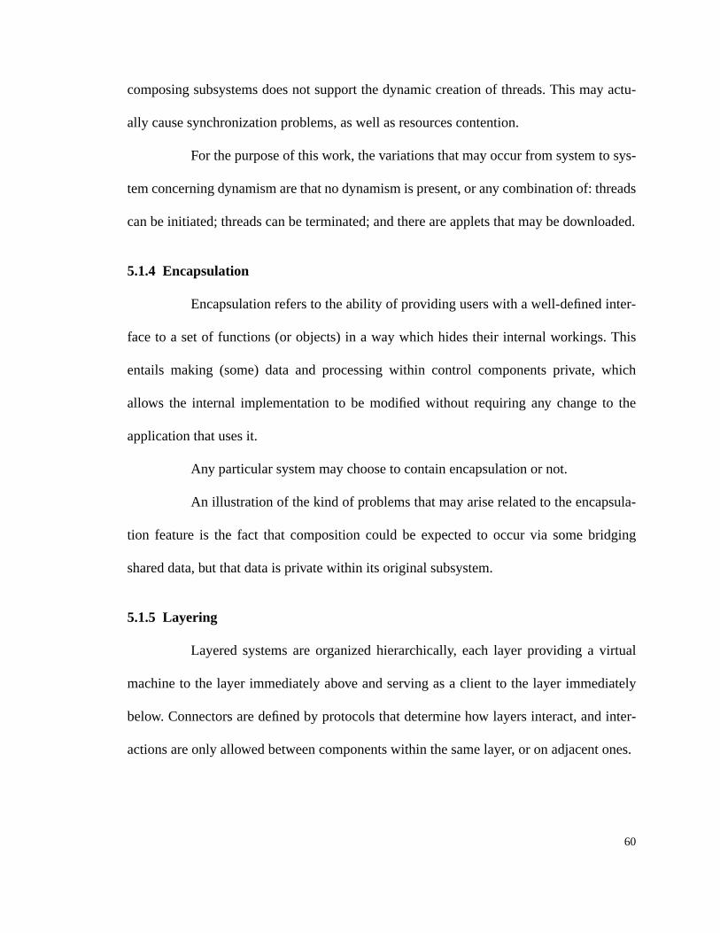
60
composing subsystems does not support the dynamic creation of threads. This may actu-
ally cause synchronization problems, as well as resources contention.
For the purpose of this work, the variations that may occur from system to sys-
tem concerning dynamism are that no dynamism is present, or any combination of: threads
can be initiated; threads can be terminated; and there are applets that may be downloaded.
5.1.4 Encapsulation
Encapsulation refers to the ability of providing users with a well-defined inter-
face to a set of functions (or objects) in a way which hides their internal workings. This
entails making (some) data and processing within control components private, which
allows the internal implementation to be modified without requiring any change to the
application that uses it.
Any particular system may choose to contain encapsulation or not.
An illustration of the kind of problems that may arise related to the encapsula-
tion feature is the fact that composition could be expected to occur via some bridging
shared data, but that data is private within its original subsystem.
5.1.5 Layering
Layered systems are organized hierarchically, each layer providing a virtual
machine to the layer immediately above and serving as a client to the layer immediately
below. Connectors are defined by protocols that determine how layers interact, and inter-
actions are only allowed between components within the same layer, or on adjacent ones.

61
Styles may or may not impose system layering constraints on its control com-
ponents. The layers must be specified with respect to a connector, e.g. a set of layers
linked by control connectors. Hence, systems may have no layering, or have layering with
respect to either control or data connectors.
During composition, the situation may be such that one of the composing sub-
systems originally included layering constraints either on control or data connectors, and
composition is achieved by extending exactly that kind of connector to such a subsystem.
The bridging connector may actually ignore these layering constraints, thus violating
them.
5.1.6 Supported Data Transfers
Of the styles we studied, all of them achieved data transfers through some
combination of: shared data variables; explicit data connectors; and shared repositories.
During composition via bridging shared data, if one of the composing sub-
systems had no shared data support, we may run into synchronization problems.
5.1.7 Triggering Capability
Hardware has interrupts, and software has triggers. Triggers are mechanisms
that initiate specific actions when certain events occur. Events can be sequences of basic
events such as a control or data transfer, or some specific time being reached. Actions can
be sequences of basic actions like a control or data transfer.
Some of the styles visited have some triggering capabilities, while others have
none.

62
During composition, if at least 2 of the composing subsystems have triggering,
and there is at least one event that has more than one trigger associated with it, one from
each of the composing subsystems (i.e, each of the composing subsystems had its own set
of actions that should occur once the event happens), then it is not clear which set of
actions should actually occur based on the composition, and if all it is not clear what the
ordering should be.
5.1.8 Backtracking
Backtracking is a scheme for solving a series of sub-problems each of which
may have multiple possible solutions and where the solution chosen for one sub-problem
may affect the possible solutions of later sub-problems. To solve the overall problem, we
find a solution to the first sub-problem and then attempt to recursively solve the other sub-
problems based on this first solution. If we cannot, or we want all possible solutions, we
backtrack and try the next possible solution to the first sub-problem and so on.
Rollback is a database management system (DBMS) feature that reverses the
current transaction out of the database, returning the database to its former state. This is
done when some failure interrupts a half-completed transaction.
Because of the similarities between the traditional definition of backtracking
and the one of rollback, this work combines both under the single name “backtracking”.
Therefore under our classification, systems (and styles) may exhibit backtracking charac-
teristics or not.

63
During composition via a bridging spawn, the spawner may belong to a sub-
system that has backtracking. This being the case, if the spawner backtracks after the
spawn has occurred, there is no pre-existing way of backtracking the state changes caused
by the spawned end.
5.1.9 Control Unit
Some styles and/or systems have a central control unit which is responsible for
arbitrating which components are to execute at any given point in time. That is, it dictates
the execution ordering based on some pre-defined mechanism. Additionally, it is possible
for systems to have distributed control units or none at all.
Hence, for our classification purpose, systems (and styles) may contain a cen-
tral control unit, distributed control units, or no control units.
An illustration of the kind of problems that may arise related to the control unit
feature is the fact that as a result of composition more than one central control unit may
exist, all of which assume they have absolute control on execution sequencing.
5.1.10 Component Priorities
Differing priorities for control components reflect the fact that some tasks’
results may be more urgent than others, or simply that previous knowledge shows that exe-
cuting some control component before another yields better results.
Many of the styles visited (see section 4.0 on page 48) grant differing priorities
to their control components. Styles and systems may require that their components exhibit
some prioritization or not.

64
An instance in which the component priorities may cause mismatches during
composition is if one of the subsystems to be composed has a prioritized structure, since
then it is not clear where a component with or without an associated priority fits in an
overall separately prioritized structure.
5.1.11 Preemption
We say we have preemption present when the scheduler can interrupt and sus-
pend (“swap out”) a currently running task in order to start or continue running (“swap
in”) another task. The tasks under preemptive multitasking can be written as though they
were the only task and the scheduler decides when to swap them. The scheduler must
ensure that when swapping tasks, sufficient state is saved and restored, and that tasks do
not interfere.
Styles and systems may require preemption to be present or not.
If composition is to be achieved via a bridging call, and the caller is preemp-
tive, while the callee is not, we may run into problems when preempting the caller,
because the callee will not be preempted.
5.1.12 Reconfiguration1
Upon some special conditions (or failures), some systems perform on-line
reconfiguration, whereas others have it done off-line. Also, some systems have on-the-fly
garbage collection, thus reconfiguring its memory space on-line.
1. This feature was not drawn from any of the specific styles visited, but it is a very relevantdescriptor for systems undergoing composition.

65
For the purpose of this work, the variations that may occur from system to sys-
tem concerning reconfiguration are that there may be on the fly garbage collection, and
reconfiguration may be done either on line or it may require off line intervention.
If at least one of the parts to be composed has on-line reconfiguration, while at
least one other has reconfiguration off-line, then upon failure only part of the resulting sys-
tem will automatically reconfigure.
5.1.13 Reentrance
A reentrant code can have multiple simultaneous, interleaved, or nested invo-
cations which will not interfere with each other. This is important for parallel processing,
recursive functions or subroutines, and interrupt handling.
It is usually easy to arrange for multiple invocations (e.g. calls to a subroutine)
to share one copy of the code and any read-only data but, for the code to be re-entrant,
each invocation must use its own copy of any modifiable data (or synchronized access to
shared data). This is most often achieved using a stack and allocating local variables in a
new stack frame for each invocation.
Systems (and styles) may contain control components that are reentrant.
When composition is to be achieved via some bridging call, and the callee is
not reentrant, it may be the case that this call occurs once the callee is already running, in
a way which contaminates the state information of the already-running invocation.
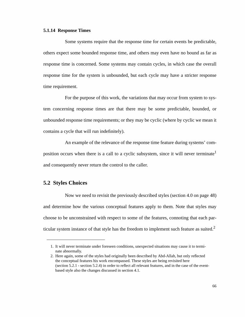
66
5.1.14 Response Times
Some systems require that the response time for certain events be predictable,
others expect some bounded response time, and others may even have no bound as far as
response time is concerned. Some systems may contain cycles, in which case the overall
response time for the system is unbounded, but each cycle may have a stricter response
time requirement.
For the purpose of this work, the variations that may occur from system to sys-
tem concerning response times are that there may be some predictable, bounded, or
unbounded response time requirements; or they may be cyclic (where by cyclic we mean it
contains a cycle that will run indefinitely).
An example of the relevance of the response time feature during systems’ com-
position occurs when there is a call to a cyclic subsystem, since it will never terminate1
and consequently never return the control to the caller.
5.2 Styles Choices
Now we need to revisit the previously described styles (section 4.0 on page 48)
and determine how the various conceptual features apply to them. Note that styles may
choose to be unconstrained with respect to some of the features, connoting that each par-
ticular system instance of that style has the freedom to implement such feature as suited.2
1. It will never terminate under foreseen conditions, unexpected situations may cause it to termi-nate abnormally.
2. Here again, some of the styles had originally been described by Abd-Allah, but only reflectedthe conceptual features his work encompassed. These styles are being revisited here(section 5.2.1 - section 5.2.4) in order to reflect all relevant features, and in the case of the event-based style also the changes discussed in section 4.1.

67
5.2.1 Distributed Processes
This style is multi-threaded and dynamic, allowing for spawns and termination
of threads, but is unconstrained with respect to applets. Data is transferred via explicit data
connectors, but it may also have shared data variables or shared repositories.
Distributed processes systems are distributed over multiple physical processor
nodes. They have no support for backtracking, and are unconstrained with respect to trig-
gering. These systems typically have unbounded response time requirements, no differen-
tiating priorities among their various control components, and no control unit.
The distributed processes style is unconstrained with respect to layering,
encapsulation, preemption, reentrance, and reconfiguration.
5.2.2 Event-Based
This style is multi-threaded and unconstrained as far as the spawning and ter-
mination of threads, or the existence of applets is concerned. It has triggering capabilities
steered by the event manager, which may be a central control unit or a set of distributed
ones. Its control components have implicit priorities, determined by the order of basic
actions to be taken upon specific event occurrences. Its systems instances typically have
unbounded response time requirements, and no support for backtracking.
The event-based style is unconstrained with respect to reentrance, its supported
data transfers, distribution, layering, encapsulation, preemption, and reconfiguration.

68
5.2.3 Main-Subroutine
The main-subroutine style is static, permitting no spawns, no terminates, and
containing no applets. It contains shared data variables, but typically no explicit data con-
nectors, nor shared repositories. It has no support for triggering, is single-threaded, and is
non-distributed.
Instance systems of the main-subroutine style usually do not support preemp-
tion or backtracking, have unbounded response time requirements, have no differentiating
priorities among their various control components, and have no control unit. Main is non-
reentrant, but other control components may be.
This style is unconstrained with respect to layering, encapsulation, and recon-
figuration.
5.2.4 Pipe-and-Filter
The pipe-and-filter style is static and multi-threaded, all filters start executing
when the system is started, and there are no spawns or terminates, but there may be
applets. Data is transferred via explicit data connectors, the pipes. It has no support for
triggering, preemption, backtracking or reentrance.
Systems of the pipe-and-filter style have unbounded response time require-
ments, no differentiating priorities among their various control components, and no con-
trol unit.
This style is unconstrained with respect to distribution, layering, encapsulation,
and reconfiguration.

69
5.2.5 Transactional Database-Centric
This style is unconstrained with respect to applets. There is data sharing via the
shared repository, the database. It has triggering capabilities guided by its central control
unit, the DBMS. It may have differentiating priorities among the various control compo-
nents depending on the kind of query they perform, and there is support for backtracking
in the form of rollback for the DBMS.
Transactional database-centric systems are typically multi-threaded, and have
response time requirements that are bounded. The DBMS is reentrant, whereas other con-
trol components are unconstrained in that respect.
The transactional database-centric style is unconstrained with respect to the
dynamic creation or termination of threads, the existence of data connectors, distribution,
layering, encapsulation, preemption, and reconfiguration.
5.2.6 Blackboard
The blackboard style may contain applets. The only means of data sharing and
transferring is via the shared repository. It has triggering capabilities guided by its central
control unit, the control unit. Its control components are prioritized, and there is support
for backtracking. Blackboard systems have no support for preemption or reentrance.
This style is unconstrained with respect to the dynamic creation or termination
of threads, concurrency, distribution, layering, encapsulation, response time requirements,
and reconfiguration.

70
5.2.7 Rule-Based
The rule-based style may have applets. The only means of data sharing and
transferring is via the shared repository of facts, the working memory. It has triggering
capabilities guided by its central control unit, the interpreter. Its control components are
prioritized, and there is support for backtracking. Rule-based systems have no support for
preemption or reentrance.
This style is unconstrained with respect to the dynamic creation or termination
of threads, concurrency, distribution, layering, encapsulation, response time requirements,
and reconfiguration.
5.2.8 Logic Programming
The logic programming style may have applets. The only means of data shar-
ing and transferring is via the shared repository of unification values. It has triggering
capabilities guided by its central control unit, the interpreter. Its control components are
prioritized, and there is support for backtracking. Logic programming systems have no
support for preemption or reentrance.
This style is unconstrained with respect to the dynamic creation or termination
of threads, concurrency, distribution, layering, encapsulation, response time requirements,
and reconfiguration.
5.2.9 Real-Time
The real-time style is multi-threaded and dynamic, allowing for spawns and
termination of threads, but no applets. It has triggering capabilities guided by its central

71
control unit, the scheduler. Its control components are prioritized, it has some predictable
response time requirements, and no support for backtracking. Real-time systems are pre-
emptive, yet non-reentrant.
This style is unconstrained with respect to its supported data transfers, distribu-
tion, layering, encapsulation, and reconfiguration.
5.2.10 Closed-Loop Feedback Control
This style uses no applets. It does have shared data variables: the controlled
variables and possibly others. Triggering capabilities are present, and dealt with by the
controller. Its systems may have one or more controller, that are their control units. At
least the processing components are preemptive, and systems have response time uncon-
strained (while each monitoring cycle has response time cyclic). There is no backtracking
present, nor any reentrance support.
The closed-loop feedback control style is unconstrained with respect to the cre-
ation and termination of threads, the existence of data connectors or shared repositories,
concurrency, distribution, layering, encapsulation, component priorities, and reconfigura-
tion.
5.2.11 Internet Distributed Entities
The internet distributed entities style is multi-threaded and dynamic, allowing
for spawns and termination of threads, and also containing downloadable applets. It has
explicit data connectors, and may have shared data variables and/or repositories. It has
triggering capabilities, is distributed and layered with respect to control connectors. Its

72
response time requirements are unbounded, and there may be support for backtracking. At
least the server is reentrant, there is on the fly garbage collection, and no control unit.
This style is unconstrained with respect to encapsulation, preemption, compo-
nent priorities, and whether there is on or off-line reconfiguration.
5.2.12 Conceptual Features Table Revisited
The discussion above on the various conceptual features and the specific
choices made by each style can be summarized as in table 6 and table 7, where✫ repre-
sents entries that were defined by Abd-Allah’s work (section 2.5),✪ represents entries that
were initially defined by Abd-Allah and later refined by this work,● represents new
entries defined and analyzed in this work, and❙ represents entries that had their specific
values changed by this work. Additionally, entries left blank mean “unconstrained.”
5.3 Conceptual Feature Space
Our conceptual feature set (section 5.1) was built by focusing on the character-
istics that seem relevant to systems’ composition. In order to understand the reasoning
behind determining what is to be considered a conceptual feature or not, one must first
comprehend the characteristics of the conceptual feature space.
First and foremost it is important to keep in mind that we are dealing with
architectural features of applications systems that are relevant to composition, not just any
kind of feature. Those clearly eliminate functional and environmental characteristics [Pri-
eto-Diaz and Freeman 1987] and go beyond signature matching [Zaremski and Wing
1993].

73
✫ DistributedProcesses
✪ Event-Based ✫ Main/ Subroutine✫ Pipe &
Filter● Database-
Centric
✫ Concurrency multi-threaded ❙ multi-threaded single-threaded multi-threaded multi-threaded
✫ Distribution multiple nodes single node
✪ Dynamism threads ❙ static, no applets static
✪ Encapsulation ❙
✫ Layering
✪ Supported datatransfers
explicit dataconnectors
❙ shared data variables explicit dataconnectors
shared repository
✫ Triggering capability yes no no yes
● Backtracking no no no no yes (rollback)
● Control unit none none none central
● Component Priorities no implicit no no
● Preemption no no
● Reconfiguration
● Reentrance no (main);unconstrained(others)
no yes
● Response Times unbounded unbounded unbounded unbounded bounded
Table 6: Instances of Our Architectural Style Space

74
● Blackboard ● Rule-Based● Logic
Programming● Real-Time
● Closed-LoopFeedbackControl
● InternetDistributed Entities
✫ Concurrency multi-threaded multi-threaded
✫ Distribution multiple nodes
✪ Dynamism threads, no applets no appletsthreads,
downloaded Applets
✪ Encapsulation
✫ Layering control
✪ Supported datatransfers
shared repository shared repository shared repository shared variablesdata connectors
✫ Triggeringcapability
yes yes yes yes yesyes
● Backtracking yes yes yes no no
● Control unit central central central central none
● ComponentPriorities
yes yes yes yes
● Preemption no no no yes yes
● Reconfigurationon the fly garbage
collection
● Reentrance no no no no no yes (server)
● Response Times predictable cyclic unbounded
Table 7: Instances of Our Architectural Style Space (cont.)

75
What we would like from a conceptual feature space is for it to have axes that
portray orthogonality of concepts, as well as support the formal description and classifica-
tion of features along them. Upon the establishment of a new style, one should then ana-
lyze it for its characteristics based on the conceptual feature space axes, to determine
whether it has some feature not presently covered.
We view the conceptual feature space as being defined by control and data flow
issues as well as organizational ones, that are complementary but yet orthogonal. In other
words, architectural features relevant to composition are those that depict how control and
data are to flow through the various components and connectors, as well as specific organi-
zational characteristics of systems. Consequently, we can discuss our conceptual feature
set by their relevance on each of these axes. Some of the conceptual features are relevant
to more than one of these dimensions, while others concentrate on a single one.
When a new style surfaces, one should then analyze it for its control flow, data
flow, and organizational characteristics, to see whether it has some feature not presently
covered. With the conceptual feature set at hand, along with considerations on how each
can affect control and/or data flow and/or organizational characteristics, we can then eval-
uate reusable parts for their features, and consequently classify them accordingly.
By classifying our current features according to our feature space we can
depict those that are related to data flow issues (figure 4), control flow issues (figure 5),
and organizational issues (figure 6).1
1. Both data and control issues axes have the ordering represent the degree of state saving required,whereas the organizational issues one represents the amount of constraints imposed on systemsby using each specific organizational scheme.
76
The control flow axis (figure 5) looks very busy still. One possible way of clus-
tering the control related information is by degree of state saving and lines of control. By
doing so, under degree of state saving we would have: triggering capability, reentrance,
preemption, reconfiguration, and backtracking; and under lines of control we would have:
concurrency, dynamism, control unit, components priorities, reentrance, and preemption.
Note that response times does not fit into either of these clusters.
Data IssuesC
oncu
rren
cy
Dat
a T
rans
fers
Bac
ktra
ckin
g
Ree
ntra
nce
&P
reem
ptio
n &
Rec
onfig
urat
ion
Trig
gerin
g
Figure 4: Data Flow Issues Axis
Control Issues
Con
curr
ency
Con
trol
Uni
t
Dyn
amis
m
Com
pone
nt P
riorit
ies
Res
pons
e T
ime
Ree
ntra
nce
Pre
empt
ion
&R
econ
figur
atio
n
Bac
ktra
ckin
g
Trig
gerin
g
Figure 5: Control Flow Issues Axis
Organizational Issues
Enc
apsu
latio
n
Laye
ring
Dis
trib
utio
n
Figure 6: Organizational Issues Axis

77
This initial effort towards defining the conceptual feature space has some
merit, laying out foundations to be further pursued in determining a more robust and for-
mal underpinning. Still it requires further study in a few directions before reaching its full
potential.
Further consideration is needed in order to determine the optimum breakout for
the control axis. We mentioned one possible way, but others do exist and may provide a
more useful partition than the one mentioned above. Moreover, a considerable amount of
work is required towards formally defining this space, as well as formally classifying its
features.
The organizational issues axis also needs further characterization, as can be
seen via the complex interaction of encapsulation, layering, and distribution in architec-
tures such as that of the Internet.
We have also done some work towards time classification of systems and what
results should be expected while performing various operations. This can be found in
appendix D.

78
6.0 Architectural Mismatches
Architectural mismatches are logical inconsistencies between constraints of
different architectures being composed. Here we describe a few examples of the mis-
matches that could be potentially found while composing with systems in the styles cov-
ered by this work (section 6.1). Subsequently, we present the mismatches table containing
a classification of the mismatches we consider relevant during systems composition, along
with explanations of the preconditions required for each of these mismatches to occur, and
the exact problem faced (section 6.2).
6.1 Architectural Mismatches Examples
To elucidate what exactly we mean by architectural mismatches, we discuss
here a few examples in a more in depth fashion.
Consider the case when we wish to have various subsystems, or parts of them,
residing in the same machine. It can be the case where these parts assume a different
underlying platform, hence we cannot have the same machine satisfy both platform
requirements. This is represented by our mismatch number 17, “Erroneous assumption of
same underlying platform.” (see section 6.2).
Another instance of architectural mismatch occurs while composing two (or
more) subsystems each of which containing a central control unit, (e.g. two event-based
subsystems, each contains its own (single) event manager). A problem arises because each
of the central control units assumes it has absolute control on execution sequencing. This

79
mismatch is our number 21, “More than one central control unit exists, all of them assum-
ing they have absolute control on execution sequencing.” (see section 6.2).
When composing 2 subsystems that have triggering, it may be the case where
there is at least one event that has more than one trigger associated with it, one from each
of the composing subsystems (i.e, each of the composing subsystems had its own set of
actions that should occur once the event happens). This situation causes problems because
it is not clear which set of actions should actually occur based on the composition, and if
all it is not clear what the ordering should be. Our mismatch number 12, “There is a non-
deterministic set of actions that could be caused by a trigger.” represents exactly this situa-
tion (see section 6.2).
6.2 Architectural Mismatches Table
Based on the newly established conceptual features (section 5.0) and the origi-
nal mismatches table introduced by Abd-Allah (section 2.5 on page 19), we introduce our
mismatches table (table 8).1
On our table we did change some of the original mismatches discussed by
Abd-Allah (his numbers 2, 3, 5, 8, and 12), we merged some, we made a few others more
generic, and still others were subsumed by some of the new ones. Consequently, the mis-
matches uncovered by Abd-Allah constitute mismatches number 1 to 11, whereas all oth-
ers were uncovered by our work.We also removed the bridging connectors triggered call,
1. Once again,✫ represents features defined by Abd-Allah,✪ represents features defined by Abd-Allah and evolved in this work, and● represents new features defined and analyzed in thiswork. New mismatches defined in this work are represented by boldface numbers in table 8.

80
triggered spawn, and triggered data transfer, and added a single bridging connector called
trigger. The items included there were just like the ones with the same kind of connectors
without “triggered,” except for the triggering capabilities row in which case the mis-
matches themselves incorporate the “triggered” factor. Additionally we renamed his
“shared machine” bridging connector to “shared resources,” making it a bit more generic.
A listing of all mismatches is given below, along with explanations of the pre-
conditions required for each of them to occur, and the exact problem faced.
1. “Two concurrent threads share data, with potential synchronization problems.”
Precondition: Composing parts are to run concurrently (regardless on whether they were
originally concurrent or not), and do share some data.
Problem: Potential synchronization problems for concurrent threads while sharing data.
2. “A layering constraint is violated.”
Precondition:Any of the composing subsystems originally included layering constraints
either on control or data connectors, and composition is achieved by extending exactly that
kind of connector to such a subsystem.
Problem:Bridging connector may ignore these constraints, thus violating them.
3. “Different sets of recognized events are used by two subsystems that permit trig-
gers.”
Precondition: At least 2 of the composing subsystems permit triggers but have different
sets of possible triggering events.

81
Cal
l
Spa
wn
Dat
aco
nnec
tor
Sha
red
data
Trig
ger
✪ S
hare
dre
sour
ces
✫ Concurrency 15, 34 9, 15, 34 34 1, 34 9, 15, 34
✪ Data transfers 7, 42 8, 42, 44 42
✫ Distribution 10 10 10 10 10
✪ Dynamism 4 45 4
✪ Encapsulation 18 19 38 20, 39 18, 19, 38, 39
✫ Layering 2 2 2 2
✫ Triggering 3, 12 3, 12 3, 12 3, 12 3, 5, 6, 12
● Backtracking 28 28 29 30 28, 29
● Control unit 21, 46 21, 46 21, 46 21, 46 21, 46
● Component Priorities 26 26 26 26 26 27
● Preemption 35 36 35, 36
● Reconfiguration 33, 37 33 33 33 33, 37
● Reentrance 24 25 23 22 23, 24, 25
● Response Times 16, 31, 37, 40, 41 32, 40, 41 40, 41 40, 41 16, 31, 32, 37, 40, 41 43
✪ Regardless 13, 14 11, 17
Table 8: Architectural Mismatches

82
Problem: A trigger may not be recognizable by some subsystem that should.
4. “A (triggered) spawn is made into or out of a subsystem which originally forbade
them.”
Precondition: Subsystems are being composed via (triggered) spawns, and at least one of
the composing subsystems does not support the dynamic creation of threads.
Problem: A (triggered) spawn is made into or out of a subsystem that originally forbade
them. May cause synchronization problems, as well as resources contention.
5. “An unrecognized triggering event is used.”
Precondition: A trigger is used as a bridging connector, but its generating event can never
occur.
Problem: The trigger will not cause the expected behavior, it will never fire the related
actions.
6. “A trigger refers to subsystems which originally forbade triggering.”
Precondition: All of the composing subsystems forbade triggering, and some of the com-
position is to be achieved via some bridging triggers.
Problem: The trigger will go by ignored, there is no underlying mechanism available to
handle the triggering.
7. “A data connector is made into a subsystem which originally forbade them.”
Precondition: Some of the composition is to be achieved via bridging data connectors, and
at least one of the composing subsystems did not originally support data connectors.

83
Problem: Unclear on how data is to be handled for sending or receiving.
8. “A shared data relationship refers to a subsystem which originally forbade them.”
Precondition: Some of the composition is to be achieved via bridging shared data, and one
of the composing subsystems had no shared data support.
Problem: May cause synchronization problems.
9. “A (triggered) spawn is made into or out of a subsystem which is not concurrent.”
Precondition: Some of the composition is to be achieved via bridging (triggered) spawns,
and one of the composing subsystems does not support the execution of concurrent
threads.
Problem: May cause synchronization problems, as well as resources contention.
10. “A remote connector is extended into or out of a non-distributed subsystem (i.e. a
subsystem originally confined to a single node).”
Precondition: One of the subsystems was originally confined to a single node, and the
resulting composed system is distributed.
Problem: The subsystem(s) originally non-distributed cannot handle delays and/or errors
occurred due to some distributed communication event.
11. “A node resource is overused.”
Precondition: Resources required are greater than the ones available at a given node.
Problem: Resource overusage such as memory and disk space.

84
12. “There is a non-deterministic set of actions that could be caused by a trigger.”
Precondition: At least 2 of the composing subsystems have triggering, and there is at least
one event that has more than one trigger associated with it, one from each of the compos-
ing subsystems (i.e, each of the composing subsystems had its own set of actions that
should occur once the event happens).
Problem: It is not clear which set of actions should actually occur based on the composi-
tion, and if all it is not clear what the ordering should be.
13. “Data connectors connecting control components that are not always active may
lead into deadlock.”
Precondition: We have a blocking bridging data connector and the receiving control com-
ponent may be inactive when data is sent through the data connector, and it may never
become active (again).
Problem: Possibility of deadlock on the control component sending the data.
14. “Data connectors connecting control components that are not always active.”
Precondition: We have a non-blocking and non-buffered bridging data connector and the
receiving control component becomes active after the data was sent and lost.
Problem: Possibility of loss of data.
15. “Erroneous assumption of single-thread.”
Precondition: A control component c1 in a single-threaded subsystem calls a control com-
ponent c2 in a multi-threaded dynamic subsystem. The problem may arise by c2 spawning

85
c3, terminating and returning control to c1, whose subsystem assumes it is running alone.
OR there is a call from a multi-threaded to a single-threaded subsystem. OR there is a
spawn from a (single or) multi-threaded subsystem to a single-threaded one, the spawnee
assumes it is running alone.
Problem: Synchronization problems on accessing shared data, and/or resource contention.
16. “(Triggered) Call to a cyclic (non-terminating) subsystem/control component.”
Precondition: There is a bridging (triggered) call to a cyclic (and hence non-terminating)
subsystem / control component.
Problem: Control will never be returned to the caller.
17. “Erroneous assumption of same underlying platform.”
Precondition: During composition we would like to have some subsystems running on a
shared machine, but they actually assume different underlying platforms.
Problem: Cannot force fit parts to a given platform.
18. “(Triggered) Call to a private method.”
Precondition: There is a bridging (triggered) call to a private method.
Problem: Method not accessible to the caller.
19. “(Triggered) Spawn to a private method.”
Precondition: There is a bridging (triggered) spawn to a private method.
Problem: Method not accessible to the spawner.

86
20. “Sharing private data.”
Precondition: Composition is also to be achieved via some bridging shared data, but that
data is private within its original subsystem.
Problem: Data not accessible to all of the sharing entities being composed.
21. “More than one central control unit exists.”
Precondition: More than one central control unit exists as a result of composition.
Problem: All central control units assume they have absolute control on execution
sequencing.
22. “Sharing data with a reentrant component.”
Precondition: Composition is to be achieved via some bridging shared data, and at least
one of the components to share it is reentrant.
Problem: Sharing of data may occur with the incorrect invocation of a component.
23. “A reentrant component is either sending or receiving a data transfer.”
Precondition: Composition is to be achieved via some bridging data connector, and at
least one of the involved control components is reentrant.
Problem: Potential incorrect assumption of which invocation of a component is either
sending or receiving a data transfer.
24. “(Triggered) Call to a non-reentrant component.”
Precondition: Composition is to be achieved via some bridging (triggered) call, and the
callee is not reentrant.

87
Problem: Component may already be running.
25. “(Triggered) Spawn to a non-reentrant component.”
Precondition: Composition is to be achieved via some bridging (triggered) spawn, and the
spawnee is not reentrant
Problem: Component may already be running.
26. “Composition involves one or more prioritized parts.”
Precondition: One of the subsystems to be composed has a prioritized structure.
Problem: Not clear where a component(s) with or without an associated priority fits in an
overall separately prioritized structure.
27. “A prioritized system sharing a machine with some other system.”
Precondition: A prioritized system sharing a machine with some other system.
Problem: Unclear on how priorities compare across the various parts, which affects the
way interrupts are to be applied.
28. “(Triggered) Call or spawn from a subsystem that may later backtrack.”
Precondition: At least one of the callers or spawners of bridging connections belongs to a
subsystem that has backtracking.
Problem: While backtracking may cause undesired side effects on the called/spawned end.

88
29. “Data being transferred from some component(s) that may later backtrack.”
Precondition: Composition is to be achieved via some bridging data connector, and the
component to send data through such a connection belongs to a subsystem that has back-
tracking.
Problem: Backtracking may cause undesired side effects on the overall composed system
state.
30. “Shared data being modified by a component(s) that may later backtrack.”
Precondition: At least one of the subsystems sharing bridging data has backtracking.
Problem: Data being shared with some component(s) that may later backtrack, thus caus-
ing possible undesired side effects on the overall composed system state.
31. “(Triggered) Call from a subsystem requiring some predictable response times to
some component(s) not originally considered.”
Precondition: Composition is to be achieved via some bridging (triggered) call, and at
least one of the calling parts requires predictable response times to some event(s).
Problem: May have side effects on original predicted response times.
32. “(Triggered) Spawn to or from a subsystem requiring some predictable response
times that involves some component(s) not originally considered.”
Precondition: Composition is to be achieved via some bridging (triggered) spawn, and at
least one of the parts involved requires predictable response times to some event(s).

89
Problem: May have side effects on original predicted response times. The original pre-
dicted response times not account for concurrently executing with these other compo-
nents.
33. “Only part of the resulting system automatically reconfigures upon failure.”
Precondition: At least one of the parts to be composed has on-line reconfiguration, and at
least one has reconfiguration off-line.
Problem: Only part of the resulting system automatically reconfigures upon failure.
34. “Some components that were expected to synchronize have different synchroniza-
tion mechanisms.”
Precondition: Composing parts are to run concurrently while synchronizing, and have dif-
ferent synchronization mechanisms.
Problem:Synchronization between concurrent parts cannot properly take place.
35. “(Triggered) Call to a component that should be preemptable and isn’t.”
Precondition: Composition is to be achieved via a bridging (triggered) call, and the caller
is preemptable, while the callee is not.
Problem: Callee will not be preempted in situations when it should.
36. “(Triggered) Spawn to a component that should be preemptable and isn’t.”
Precondition: Composition is to be achieved via a bridging (triggered) spawn, and the
spawner is preemptable, while the spawnee is not.
Problem: Spawnee will not be preempted in situations when it should.

90
37. “(Triggered) Call to a component that performs on the fly garbage collection.”
Precondition: Composition is to be achieved via a bridging (triggered) call, the callee per-
forms on the fly garbage collection, while the caller has requirements for some predictable
or bounded response times.
Problem: Undesirable side effects on the overall predictable or bounded response times.
38. “Incorrect assumption of which instantiation of an object is either sending or
receiving a data transfer.”
Precondition: Composition is to be achieved via a bridging data connector, and at least
one of the parts affected by such connection has encapsulation.
Problem: Incorrect assumption of which instantiation of an object is either sending or
receiving a data transfer.
39. “Sharing data with the incorrect instantiation of an object.”
Precondition: Composition is to be achieved via some bridging shared data, and at least
one of the parts involved has encapsulation.
Problem: Sharing data with the incorrect instantiation of an object.
40. “Time represented/compared using different granularities.”
Precondition: More than one of the composing parts has response time different than
unbounded and cyclic unbounded. Additionally, they are distributed over machines that
represent and/or compare time using different granularities.
Problem: Communications concerning time cannot properly occur.

91
41. “Absolute time values are off.”
Precondition: More than one of the composing parts has response time different than
unbounded and cyclic unbounded. Additionally, they are distributed over machines that
have their wall-clock time off.
Problem: Communications concerning time cannot properly occur.
42. “Sharing or transferring data with differing underlying representations.”
Precondition: Sharing or transferring data with differing underlying representations,
including differences in data formats, units and coordinate systems.
Problem: Communications concerning the specific data will not properly occur.
43. “Resource contention.”
Precondition: Two or more parts are co-hosted, with at least one requiring some predict-
able response time, and the original analysis did not take into account some of the parts
that are currently co-hosted.
Problem: Predictable response time indirectly affected because there may be some
resource contention not originally considered.
44. “Potential database and/or DBMS heterogeneity problems may occur.”
Precondition: Two or more repositories are present.
Problem: Our model does not support for checking the specifics here, but problems may
arise on semantic heterogeneity, differing data items granularity, databases being distrib-
92
uted or not, databases being replicated or not, and/or databases having different structural
organizations.
45. “Inaccessible shared data.”
Precondition: Composition is being achieved by having an applet share data that is local to
the client side.
Problem: Applets have no access to the local file system of the client side (i.e., the applet
cannot really access the data that is to be shared).
46. “Distributed control units are present.”
Precondition: Two or more of the composing subsystems have distributed control units.
Problem: Incorrect assumption that a problem is being solved elsewhere, by some other
control unit.

93

93
7.0 Modeling Styles and Their Features
This section contains all information relevant to the Z model, as well as the
model itself. We start here by presenting the changes required by the base elements’ set
and Abd-Allah’s original model (section 7.1).1 Subsequently we provide guidelines as on
how to reflect systems and/or styles features by using the basic framework provided
(section 7.2).
As seen in section 7.3, we have spent some effort revisiting all of Abd-Allah’s
styles descriptions. This was required in order to reflect the changes to the base elements,
as well as each of the styles full set of feature choices.2 This section also contains the Z
models of all styles we are addressing. The model for detecting mismatches and compos-
ing systems is introduced in section 7.4.
7.1 Basic Entities’ Model
In order to reflect our judgment in the model it had to evolve considerably,
many of the existing basic entities were modified, and numerous support additions
occurred. Here we simply list the main ones. Their details can be found in appendix C on
page 224.
• Basic support additions:
1. A full uninterrupted version of our model can be found in appendix C, and Abd-Allah’s inappendix B
2. Abd-Allah’s model of the event-based style was changed considerably more than the others.What we have done was to have the existence of an event manager propagate into the Z model.This actually allows for the detection of one more potential architecture compositional mis-match.

94
• BasicAction: schema describing a single action as being either a control or a
data transfer.
• BAtype: type indicating whether a basic action is a control or a data transfer.
• BasicEvent:schema describing a single event as being either a control or a data
transfer, or some absolute time being reached.
• BEtype: type indicating whether a basic event is a control or a data transfer, or
some absolute time being reached.
• CCtype: type for indicating what type a control component has
• CCNtype: type for indicating what type a control connector has
• RTimetype: type for indicating possible expected response times
• Reconfiguration_type: type for indicating the kinds of reconfiguration sup-
ported by systems
• check_basicevents: function that makes sure the basic events composing a given
event (sequence) belong to either one of the given control or data transfer event
sets or to some time checking event.
• check_basicactions: function that makes sure the basic actions composing a
given action (sequence) belong to either one of the given control or data transfer
action sets.
• gettriggeredcontrolcmp: function that returns all the triggered control compo-
nents, regardless of the kind of action (actually, the parameters are a sequence
of basic actions and the kind of control transfer we are looking for).

95
• generates_basicactions: function that makes sure the basic actions composing a
given action (sequence) are generated by the given control component.
• gettriggeredcalls: function for recursively retrieving all the triggered calls asso-
ciated with a set of actions, each being a sequence of basic actions.
• gettriggeredspawns: function for recursively retrieving all the triggered spawns
associated with a set of actions, each being a sequence of basic actions.
• SynchronizationMechanism: given set of synchronization mechanisms
• added Java as another possible implementation language
• New schemas and/or relations:
• Action: actual actions are sequences of basic actions
• Event: actual events are sequences of basic events
• DataTransfer: Z abbreviation definition for a data connector, the 2 control com-
ponents it can transfer data between, and the various data components that can
be sent in the specific situation. The effects of a data transfer are reflected in the
schema ActualDataTransfer.
• ControlTransfer: Z abbreviation definition for a control connector and the 2
control components it can transfer control between. The effects of a control
transfer are reflected in the schema ActualControlTransfer.
• Return: new kind of control connector to be paired with calls and spawns.
• Interrupt: new kind of control connector.
• Swap_In: new kind of control connector to be paired with interrupts.
• Terminate: new kind of control connector.

96
• CallReturn: actually pairing calls with theirs respective returns.
• SpawnReturn: actually pairing spawns with their respective returns.
• InterruptSwapIn: actually pairing interrupts with theirs respective swap-ins.
• Time: schema for time representation.
• TimeGranularity: the type of granularity used for some time representation.
• Schemas removed:
• Object is no longer a schema, but a specialization of ControlComponent.
• Trigger is no longer a schema but a relation matching between Events
(sequences of basic events) and Actions (sequences of basic actions).
• Changes to pre-existing schemas:
• under system:
• added the sets of running control components, inactive control compo-
nents, and suspended control components. All of these are used by the
operations ActualDataTransfer, ActualControlTransfer, and StartSystem:
• added repositories, control units, response_time, reconfiguration, back-
tracking, and synchronization mechanisms. These were required in order
to represent various new features.
• under node:
• added wall_clock_time, time_representation, and resources. These addi-
tions allow us to check for a few other mismatches.
• under controlcomponent:

97
• priority, applet, preemptive, response_time, reentrant, invocation. All of
these were required for some features representations.
• Operations:
• StartSystem: starts the system as having all the initialcontrolcmps running, no
control components suspended, and all others inactive.
• ActualDataTransfer: confirms that the actual data transfer can occur at that
given point in time.
• ActualControlTransfer: Reflects the effects of control transfers within a system
by updating the set of its running, inactive, or suspended control components. It
also performs some checks for the mismatches that include dynamic character-
istics.
• General fixes:
• Made sure that the directionality in data connectors corresponds to the charac-
teristics of the ports they are attached to.
• Changed shared data under system so that now it is a set of all shared data, not
just a single data component being shared.
• Made sure that the resources on each of the system’s nodes are enough to sup-
port all parts that reside on them.

98
Clearly all additions, changes and removals impose some propagation effect on
other existing entities specially in the form of new constraints.1 Although those were not
made explicit here they were incorporated in the model.
7.2 Modeling the Conceptual Features
The various features we discussed in section 5.0 are reflected in the model of
systems and styles by using the underlying framework that we have devised. We describe
here how to model each one of them. For examples on these guidelines been applied see
section 7.3. The items mentioned here are the main points, but as it can be seen in the
model, each one of them implies many other restrictions that are represented via various
entities’ constraints (see appendix C).
• Dynamism:
• threads initiating: system has spawns
• threads terminating: system has terminates
• downloaded applets: system has at least one control component that is an applet
• none: system has no spawns, terminates, or control component that is an applet
• Supported Data Transfers:
• shared data variables: system has shared data variables
• explicit data connectors: system has explicit data connectors
• shared repositories: system has shared repositories
1. For example, the union of set of running, inactive, and suspended control components that arepart of a system yields this system’s set of control components. Additionally, the set of running,inactive, and suspended control components of a system are disjoint. These sets evolve as thesystem is started, and control transfers occur.

99
• none: system has no shared data variables, explicit data connectors, or shared
repositories
• Triggering Capability:
• yes: system has triggers
• no: system has no triggers
• Concurrency:
• yes: system has spawns and/or more than one initial control component
• no: system has no spawns, nor more than one initial control component
• Distribution:
• single node: all system’s parts reside on a single node
• multiple nodes: system’s parts are distributed over more than one node
• Layering:
• data: system has dataconnector layers
• control: system has call or spawn layers
• none: system has no (call/spawn/dataconnector) layers
• Encapsulation:
• yes: system has objects
• no: system has no objects
• Backtracking:
• yes: system has backtracking TRUE
• no: system has backtracking FALSE
• Component Priorities:

100
• yes: system has at least one control component with priority different than 0
• no: system has no control component with priority different than 0
• Control Unit
• central: system has single control unit
• distributed: system has more than one control unit
• none: system has no control unit
• Preemption:
• yes: there is at least one control component that is preemptive
• no: there is no control component that is preemptive
• Reconfiguration:
• on-line: system has reconfiguration = {online}
• off-line: system has reconfiguration = {offline}
• system may also have reconfiguration be a combination of (on or off line) and
on the fly garbage collection
• Reentrance:
• yes: system has at least one control component with reentrant TRUE
• no: system has no control component with reentrant TRUE
• Response Times:
• predictable: system has response_time predictable
• bounded: system has response_time bounded
• unbounded: system has response_time unbounded
• cyclic: system has response_time cyclic

101
7.3 Complete Model of Styles
Below we have included our model of the various styles we address, while
reflecting their various features according to table 6 on page 73 and table 7 on page 74,
and the guidelines provided above (section 7.2).
While most of the styles initially described by Abd-Allah evolved only as to
reflect the new set of features (and changes to the basic model entities) we are using, his
event-based style description changed considerably. The Event Based style is now multi-
threaded and unconstrained with respect to dynamism, and the actual existence of the
event manager is reflected in the model.
7.3.1 Pipe and Filter
% Pipe & Filter Styleglobal
PF_DataStructure : P DataComponent;PF_Socket : P Port;PF_Pipe : P DataConnector;PF_Filter : P ControlComponent;PF_System : P System;
axiomforall s : PF_Socket @
% No socket is used for both input and outputs.iotype /= io_inout and% All data transfers are streameds.streaming = TRUE;
forall p : PF_Pipe @% Pipes always connect filters and not objectsp.c1.type = other andp.c2.type = other and% Unidirectionalp.directionality = forward and% Pipe connects two filters{p.c1, p.c2} subseteq PF_Filter and% Ports belong to the P/F style{p.p1, p.p2} subseteq PF_Socket and% p1 acts as sender, p2 acts as receiverp.p1.iotype = io_out and p.p2.iotype = io_in and% The sender socket is different than the receiver
102
p.p1 /= p.p2;forall f : PF_Filter @
% Ports belong to the P/F stylef.ports subseteq PF_Socket andf.locals subseteq PF_DataStructure and% There are no applets among the filters.f.applet = FALSE and% No filter is preemptive.f.preemptive = FALSE and% Filters have no associated priorities.f.priority = 0 and% Filters are non-reentrant.f.reentrant = FALSE;
forall s : PF_System @s in MultiThreadedSystems ands.controlcomponents subseteq PF_Filter ands.dataconnectors subseteq PF_Pipe ands.globalobjs = {} ands.controlconnectors = {} ands.shareddata = {} ands.repositories = {} ands.triggers = {} ands.initialcontrolcmps = s.controlcomponents ands.initialdataconnectors = s.dataconnectors ands.response_time = unbounded and% PF systems have no backtracking.s.backtracking = FALSE and% PF systems have no control unitss.controlunit = {} and% All pipe sockets connect filter sockets(forall p : s.dataconnectors @
exists f1, f2 : s.controlcomponents @p.p1 in f1.ports and p.p2 in f2.ports) and
% No two pipes connect the same sender and receiver(forall p1, p2 : s.dataconnectors @
((p1.p1 = p2.p1 and p1.p2 = p2.p2) => p1 = p2));end axiom
7.3.2 Main/Subroutine
% Main / Subroutine Styleglobal
MS_DataStructure : P DataComponent;MS_Procedure : P ControlComponent;MS_ProcedureCall : P Call;MS_System : P System;
axiomforall p : MS_Procedure @
p.ports = {} and

103
p.locals subseteq MS_DataStructure and% There are no applets among the procedures.p.applet = FALSE and% No procedure is preemptive.p.preemptive = FALSE and% Procedures have no associated priorities.p.priority = 0;
forall pc : MS_ProcedureCall @% Call connects two procedures{pc.c1, pc.c2} subseteq MS_Procedure and% Procedure calls cannot be queuedpc.queuesize = 0;
forall s : MS_System @s.controlcomponents subseteq MS_Procedure anddom s.shareddata subseteq MS_DataStructure ands.repositories = {} ands.calls subseteq MS_ProcedureCall and% MS systems have only calls and returns as control connectors.(forall cn : ControlConnector | cn in s.controlconnectors @
(cn.type = call or cn.type = return)) ands.dataconnectors = {} ands.triggers = {} ands.response_time = unbounded and% MS systems have no backtracking.s.backtracking = FALSE and% MS systems have no control unitss.controlunit = {} and% MS systems have a single initial control component, main.# s.initialcontrolcmps = 1 and% All M/S systems have a single thread# (getmaxthreads(s)) = 1 and% System forms a connected, directed graph of calls starting from main(exists main : MS_Procedure; subroutines : P MS_Procedure @
s.initialcontrolcmps = {main} and{main} setunion subroutines = s.controlcomponents andmain notin subroutines and% Main is non-reentrantmain.reentrant = FALSE and(forall call : s.calls @ call.c2 /= main) andcdgraph (main, subroutines) = {c1, c2 : MS_Procedure |
exists call : s.calls @ call.c1 = c2 and call.c2 = c2}) and% The system rests on one node# {n : Node |
(exists c : ControlComponent | c in s.controlcomponents @ n in c.nodes) or(exists call : ControlConnector | call in s.calls @ n in call.nodes)} = 1;
end axiom

104
7.3.3 Distributed Processes
% Distributed Processes Styleglobal
DP_DataStructure : P DataComponent;DP_Socket : P Port;DP_Process : P ControlComponent;DP_Circuit : P DataConnector;DP_ProcessCall : P Call;DP_ProcessSpawn : P Spawn;DP_System : P System;
axiomforall s : DP_Socket @
s.iotype = io_inout;forall p : DP_Process @
p.ports subseteq DP_Socket andp.locals subseteq DP_DataStructure and% There are no applets among the processesp.applet = FALSE and% Processes have no associated priorities.p.priority = 0;
forall c : DP_Circuit @{c.p1, c.p2} subseteq DP_Socket and{c.c1, c.c2} subseteq DP_Process and% Bidirectionalc.directionality = twoway;
forall pc : DP_ProcessCall @% Call connects two processes{pc.c1, pc.c2} subseteq DP_Process and% Process calls cannot be queuedpc.queuesize = 0;
forall ps : DP_ProcessSpawn @% Spawn connects two processes{ps.c1, ps.c2} subseteq DP_Process and% Process spawn cannot be queuedps.queuesize = 0;
forall s : DP_System @s in MultiThreadedSystems and% The system rests on more than one nodes in DistributedSystems ands.controlcomponents subseteq DP_Process ands.dataconnectors subseteq DP_Circuit and% DP systems have calls, spawns, returns, and possibly interrupts (& swap-
ins), and terminates.s.calls subseteq DP_ProcessCall ands.spawns subseteq DP_ProcessSpawn ands.shareddata = {} ands.repositories = {} ands.response_time = unbounded and% DP systems have no backtracking.

105
s.backtracking = FALSE and% DP systems have no control unitss.controlunit = {} and% All circuit sockets connect process sockets(forall c : s.dataconnectors @
exists p1, p2 : s.controlcomponents @c.p1 in p1.ports and c.p2 in p2.ports) and
% No two circuits connect the same pair of sockets(forall c1, c2 : s.dataconnectors @
c1 /= c2 =>(not (c1.p1 = c2.p1 and c1.p2 = c2.p2)) and(not (c1.p1 = c2.p2 and c1.p2 = c2.p1)));
end axiom
7.3.4 Event-Based
% Event-Based (implicit invocation) Styleglobal
EB_DataStructure : P DataComponent;EB_Procedure : P ControlComponent;EB_ProcedureCall : P Call;EB_ProcedureSpawn : P Spawn;EB_EventManager: P ControlComponent;EB_Event : P Event;EB_Action : P Action;EB_Trigger : P Trigger;EB_System : P System;
axiomforall p : EB_Procedure @
p.locals subseteq EB_DataStructure andp.ports = {} and% There are no applets among the proceduresp.applet = FALSE and% Processes have no associated priorities. They are burried within the event
manager and how it handles the triggering events.p.priority = 0;
forall pc : EB_ProcedureCall @% Call connects two procedures, or the event manager and a procedure, but
no procedure can call the event manager{pc.c1, pc.c2} subseteq (EB_Procedure setunion EB_EventManager) andpc.c2 notin EB_EventManager and% Procedure calls cannot be queuedpc.queuesize = 0;
forall ps : EB_ProcedureSpawn @% Spawn connects two procedures, or the event manager and a procedure,
but no procedure can spawn the event manager{ps.c1, ps.c2} subseteq (EB_Procedure setunion EB_EventManager) andps.c2 notin EB_EventManager and% Procedure spawns cannot be queued

106
ps.queuesize = 0;forall em : EB_EventManager @
em.locals subseteq EB_DataStructure and% It is not an applet.em.applet = FALSE;
forall t : EB_Trigger @% All triggers are composed of events and actions that belong to the system(exists e : EB_Event; a : EB_Action @
((e, a) = t and% The event manager is actually initiating all triggered actions(exists em : EB_EventManager @
generates_basicactions(em, a) = TRUE)));forall s : EB_System @
s in MultiThreadedSystems ands.controlcomponents subseteq (EB_Procedure setunion EB_EventManager)
anddom s.shareddata subseteq EB_DataStructure and% There can be one or more event managers# {em: EB_EventManager | em in s.controlcomponents} >= 1 and% The event manager is always running.(forall em : EB_EventManager | em in s.controlcomponents @
em in s.runningcontrolcmps) and% EB systems have calls, spawns, returns and possibly interrupts (& swap-
ins), and terminates.s.calls subseteq EB_ProcedureCall ands.spawns subseteq EB_ProcedureSpawn ands.events subseteq EB_Event ands.actions subseteq EB_Action ands.triggers subseteq EB_Trigger ands.triggers /= {} ands.response_time = unbounded and% EB systems have no backtracking.s.backtracking = FALSE and% EB systems have their event managers as control units.s.controlunit = {em: EB_EventManager | em in s.controlcomponents};
end axiom
7.3.5 Blackboard
% Blackboard Styleglobal
BB_DataStructure : P DataComponent;BB_Blackboard_Data : P DataComponent;BB_Ksource : P ControlComponent;BB_CtrlUnit : P ControlComponent;BB_Activation : P ControlConnector;BB_Terminate : P Terminate;BB_System : P System;
axiom

107
forall bdata : BB_Blackboard_Data @bdata in BB_DataStructure;
forall ksource : BB_Ksource @ksource.ports = {} andksource.locals subseteq BB_DataStructure and% There are no applets among the knowledge sources.ksource.applet = FALSE and% No knowledge source is preemptive.ksource.preemptive = FALSE and% Knowledge sources have associated priorities.ksource.priority >= 0 and% Knowledge sources are non-reentrant.ksource.reentrant = FALSE;
forall cunit : BB_CtrlUnit @cunit.ports = {} andcunit.locals subseteq BB_DataStructure and% The control unit is not an applet.cunit.applet = FALSE and% It is not preemptive.cunit.preemptive = FALSE and% It is non-reentrant.cunit.reentrant = FALSE;
forall a : BB_Activation @% Activations are made from the control unit to the various knowledge sources
only.a.c1 in BB_CtrlUnit anda.c2 in BB_Ksource and% Activations are either calls or spawns(a.type = call or a.type = spawn) and% Activations cannot be queueda.queuesize = 0;
forall s : BB_System @% There is exactly one blackboard repository# s.repositories = 1 and% There is exactly one control unit# {cunit : BB_CtrlUnit | cunit in s.controlcomponents} = 1 and% There is at least one knowledge source# {ksource : BB_Ksource | ksource in s.controlcomponents} >= 1 and% All knowledge sources have activations connecting to them(forall ksource : BB_Ksource |
ksource in s.controlcomponents @(exists a : BB_Activation @ a.c2 = ksource)) and
% All control connectors that happen within the system are activations, returns,and terminates.
(s.calls setunion s.spawns) subseteq BB_Activation ands.terminates subseteq BB_Terminate and(forall cn : ControlConnector | cn in s.controlconnectors @
cn.type = call or cn.type = spawn or cn.type = return or cn.type = terminate)and
s.dataconnectors = {} ands.shareddata = {} and

108
s.triggers /= {} and% The control unit initiates all triggered actions.(forall t : Trigger | t in s.triggers @
(exists e : Event; a : Action @((e, a) = t and(exists cunit : BB_CtrlUnit @generates_basicactions(cunit, a) = TRUE)))) and
% BB systems have backtracking.s.backtracking = TRUE and% BB systems have a central control unit, the control unit.s.controlunit = {cunit : BB_CtrlUnit | cunit in s.controlcomponents} and# {cunit: BB_CtrlUnit | cunit in s.controlunit} = 1 and% There is only 1 initial control component, the control unit.# s.initialcontrolcmps = 1 and(exists cunit : BB_CtrlUnit; ksource : P BB_Ksource @
s.initialcontrolcmps = {cunit} and% All control components are either knowledge sources or the control unit.{cunit} setunion ksource = s.controlcomponents andcunit notin ksource and% Nobody can call or spawn the control unit.not (exists call : s.calls @ call.c2 = cunit) andnot (exists spawn : s.spawns @ spawn.c2 = cunit) and% The system is a directed graph on a star configuration (dstar), where the
center is the control unit, and the edges are system calls or spawns(activation calls or spawns to be more specific).
dstar(cunit, ksource) = {c1, c2 : s.controlcomponents |exists cn : s.controlconnectors |
(cn in s.calls or cn in s.spawns) @cn.c1 = c1 and cn.c2 = c2}) and
% All blackboard data is visible to the control unit via the repository, all controlcomponents that can see that data belong to the system (i.e., they areeither any of its knowledge sources or its control unit), and all controlcomponents that belong to the system can see the data.
(forall r : s.repositories @(forall bbdata : P DataComponent |
bbdata subseteq BB_Blackboard_Data @(exists cset : P ControlComponent; cunit : BB_CtrlUnit @
bbdata = r.data andcset = r.accessingcmps andcunit in cset andcset = s.controlcomponents)));
end axiom
7.3.6 Database Centric
% Database Centric Styleglobal
DB_DataStructure : P DataComponent;DB_Data : P DataComponent;

109
DB_UsingComponent : P ControlComponent;DB_SupportComponent : P ControlComponent;DB_DBMS : P ControlComponent;DB_Request : P Call;DB_Check : P Spawn;DB_System : P System;
axiomforall data : DB_Data @
data in DB_DataStructure;forall u : DB_UsingComponent @
u.locals subseteq DB_DataStructure;forall s : DB_SupportComponent @
s.locals subseteq DB_DataStructure;forall d : DB_DBMS @
d.locals subseteq DB_DataStructure and% The dbms is reentrant.d.reentrant = TRUE;
forall r : DB_Request @% Requests are made from the using and support control components to the
DBMS.r.c1 in (DB_UsingComponent setunion DB_SupportComponent) andr.c2 in DB_DBMS;
forall c : DB_Check @% Checks are made from the DBMS to the support control components.c.c1 in DB_DBMS andc.c2 in DB_SupportComponent;
forall s : DB_System @s in MultiThreadedSystems and% There are one or more database repositories# s.repositories >= 1 and% There is exactly one dbms# {dbms : DB_DBMS | dbms in s.controlcomponents} = 1 and% There is at least one using control component# {u_cmp : DB_UsingComponent | u_cmp in s.controlcomponents} >= 1 and% All using control components have requests associated to them(forall u_cmp : DB_UsingComponent | u_cmp in s.controlcomponents @
(exists r : DB_Request @ r.c1 = u_cmp)) and% All supporting control components have checks connecting to them(forall s_cmp : DB_SupportComponent | s_cmp in s.controlcomponents @
(exists c : DB_Check @ c.c2 = s_cmp)) and% All control connectors that happen within the system are either checks,
requests, their returns, and possibly interrupts (& swap-ins), and termi-nates.
(s.calls setunion s.spawns) subseteq (DB_Check setunion DB_Request) and% There are no applets among the control components.(forall c : ControlComponent | c in s.controlcomponents @
c.applet = FALSE) ands.shareddata = {} ands.triggers /= {} and% The DBMS initiates all triggered actions.(forall t : Trigger | t in s.triggers @

110
(exists e : Event; a : Action @((e, a) = t and(exists dbms : DB_DBMS @generates_basicactions(dbms, a) = TRUE)))) and
s.response_time = bounded and% DB systems have backtracking for rollback, maintaining data integrity and
conscistency.s.backtracking = TRUE and% DB systems have a central control unit, the dbms.s.controlunit = {dbms : DB_DBMS | dbms in s.controlcomponents} and# {dbms : DB_DBMS | dbms in s.controlunit} = 1 and(exists dbms : DB_DBMS; u_cmps : P DB_UsingComponent; s_cmps : P
DB_SupportComponent @% The DBMS is always running.dbms in s.runningcontrolcmps and% All control components are either the dbms, using components, or sup-
port components.{dbms} setunion u_cmps setunion s_cmps = s.controlcomponents anddbms notin (u_cmps setunion s_cmps) and% The system is an undirected graph on a star configuration (ustar), where
the center is the dbms, and the edges are system calls or spawns(requestes or checks).
(exists cmps : P ControlComponent |(cmps subseteq s.controlcomponents) @ustar(cmps) = {c1, c2 : s.controlcomponents |
exists cn : s.controlconnectors |(cn in s.calls or cn in s.spawns) @((cn.c1 = c1 and cn.c2 = c2) or(cn.c1 = c2 and cn.c2 = c1))})) and
% All database data is visible to the dbms via the repository, all control compo-nents that can see that data belong to the system.
(forall r : s.repositories @(forall dbdata : P DataComponent |
dbdata subseteq DB_Data @(exists cset : P ControlComponent; dbms : DB_DBMS @
dbdata = r.data andcset = r.accessingcmps andr.persistent = TRUE anddbms in cset andcset subseteq s.controlcomponents)));
end axiom
7.3.7 Rule-Based
% Rule-Based Styleglobal
RB_DataStructure : P DataComponent;RB_Fact : P DataComponent;RB_Rule : P ControlComponent;

111
RB_Interpreter : P ControlComponent;RB_Fire : P ControlConnector;RB_Terminate : P Terminate;RB_System : P System;
axiomforall f : RB_Fact @
f in RB_DataStructure;forall r : RB_Rule @
r.ports = {} andr.locals = {} and% Rules are not applets.r.applet = FALSE and% Rules are non-preemptive.r.preemptive = FALSE and% Rules have associated priorities.r.priority >= 0 and% Rules are non-reentrant.r.reentrant = FALSE;
forall i : RB_Interpreter @i.ports = {} andi.locals = {} and% Interpreters are not applets.i.applet = FALSE and% Interpreters are non-preemptive.i.preemptive = FALSE and% Interpreters are non-reentrant.i.reentrant = FALSE;
forall f : RB_Fire @% The fireing of rules is made by the interpreter.f.c1 in RB_Interpreter andf.c2 in RB_Rule and% Rules fireing can be either calls or spawns.(f.type = call or f.type = spawn);
forall t : RB_Terminate @% The termination of rules is made by the interpreter.t.c1 in RB_Interpreter andt.c2 in RB_Rule;
forall s : RB_System @% There is a single repository, the working memory.# s.repositories = 1 and% There is exactly one interpreter# {i : RB_Interpreter | i in s.controlcomponents} = 1 and% There is at least one rule# {r : RB_Rule | r in s.controlcomponents} >= 1 and% All rules have some fireing mechanism associated to them.(forall rule : RB_Rule | rule in s.controlcomponents @
(exists f : RB_Fire @ f.c1 = rule)) ands.dataconnectors = {} and% All control connectors that happen within the system are either rules fireing,
returning or terminating.(s.calls setunion s.spawns) subseteq RB_Fire and
112
s.terminates subseteq RB_Terminate and(forall cn : ControlConnector | cn in s.controlconnectors @
cn.type = call or cn.type = spawn or cn.type = return or cn.type = terminate)and
s.shareddata = {} ands.triggers /= {} and% The interpreter initiates all triggered actions.(forall t : Trigger | t in s.triggers @
(exists e : Event; a : Action @((e, a) = t and(exists interp : RB_Interpreter @generates_basicactions(interp, a) = TRUE)))) and
% RB systems have backtracking to support for backward chaining.s.backtracking = TRUE and% RB systems have a central control unit, the interpreter.s.controlunit = {i : RB_Interpreter | i in s.controlcomponents} and# {i : RB_Interpreter | i in s.controlunit} = 1 and% There is only 1 initial control component, the interpreter.# s.initialcontrolcmps = 1 and(exists interp : RB_Interpreter; rules : P RB_Rule @
s.initialcontrolcmps = {interp} and% All control components are either the interpreter or rules.{interp} setunion rules = s.controlcomponents andinterp notin rules and% The system is a directed graph on a star configuration (dstar), where the
center is the interpreter, and the edges are system calls or spawns(fires).
dstar(interp, rules) = {c1, c2 : s.controlcomponents |exists cn : s.controlconnectors |
(cn in s.calls or cn in s.spawns) @cn.c1 = c1 and cn.c2 = c2}) and
% All working memory data is visible to the interpreter via the repository, allcontrol components that can see that data belong to the system, and allcontrol components that belong to the system can see the data.
(forall r : s.repositories @(forall fact : P DataComponent |
fact subseteq RB_Fact @(exists cset : P ControlComponent; interp : RB_Interpreter @
fact = r.data andcset = r.accessingcmps andinterp in cset andcset = s.controlcomponents)));
end axiom
7.3.8 Logic-Programming
% Logic-Programming Styleglobal
LP_DataStructure : P DataComponent;

113
LP_UnificationValue : P DataComponent;LP_Rule : P ControlComponent;LP_Interpreter : P ControlComponent;LP_Invoke : P ControlConnector;LP_Terminate : P Terminate;LP_System : P System;
axiomforall u : LP_UnificationValue @
u in LP_DataStructure;forall r : LP_Rule @
r.ports = {} andr.locals = {} and% Rules are not applets.r.applet = FALSE and% Rules are non-preemptive.r.preemptive = FALSE and% Rules have associated priorities.r.priority >= 0 and% Rules are non-reentrant.r.reentrant = FALSE;
forall i : LP_Interpreter @i.ports = {} andi.locals = {} and% Interpreters are not applets.i.applet = FALSE and% Interpreters are non-preemptive.i.preemptive = FALSE and% Interpreters are non-reentrant.i.reentrant = FALSE;
forall i : LP_Invoke @% The invocation of rules is made by the interpreter.i.c1 in LP_Interpreter andi.c2 in LP_Rule and% Rules’ invocation can be either calls or spawns.(i.type = call or i.type = spawn);
forall t : LP_Terminate @% The termination of rules is made by the interpreter.t.c1 in LP_Interpreter andt.c2 in LP_Rule;
forall s : LP_System @% There is a single repository.# s.repositories = 1 and% There is exactly one interpreter# {i : LP_Interpreter | i in s.controlcomponents} = 1 and% There is at least one rule# {r : LP_Rule | r in s.controlcomponents} >= 1 and% All rules have some invocation mechanism associated to them.(forall rule : LP_Rule | rule in s.controlcomponents @
(exists i : LP_Invoke @ i.c1 = rule)) ands.dataconnectors = {} and% All control connectors that happen within the system are either rules’ invoca-

114
tions, returns, or terminations.(s.calls setunion s.spawns) subseteq LP_Invoke ands.terminates subseteq LP_Terminate and(forall cn : ControlConnector | cn in s.controlconnectors @
cn.type = call or cn.type = spawn or cn.type = return or cn.type = terminate)and
s.shareddata = {} ands.triggers /= {} and% The interpreter initiates all triggered actions.(forall t : Trigger | t in s.triggers @
(exists e : Event; a : Action @((e, a) = t and(exists interp : LP_Interpreter @generates_basicactions(interp, a) = TRUE)))) and
% LP systems have backtracking to support for backward chaining.s.backtracking = TRUE and% LP systems have a central control unit, the interpreter.s.controlunit = {i : LP_Interpreter | i in s.controlcomponents} and# {i : LP_Interpreter | i in s.controlunit} = 1 and% There is only 1 initial control component, the interpreter.# s.initialcontrolcmps = 1 and(exists interp : LP_Interpreter; rules : P LP_Rule @
s.initialcontrolcmps = {interp} and% All control components are either the interpreter or rules.{interp} setunion rules = s.controlcomponents andinterp notin rules and% The system is a directed graph on a star configuration (dstar), where the
center is the interpreter, and the edges are system calls or spawns(invocations).
dstar(interp, rules) = {c1, c2 : s.controlcomponents |exists cn : s.controlconnectors |
(cn in s.calls or cn in s.spawns) @cn.c1 = c1 and cn.c2 = c2}) and
% All unification values are visible to the interpreter via the repository, all con-trol components that can see these values belong to the system, and allcontrol components that belong to the system can see the values.
(forall r : s.repositories @(forall unifval : P DataComponent |
unifval subseteq LP_UnificationValue @(exists cset : P ControlComponent; interp : LP_Interpreter @
unifval = r.data andcset = r.accessingcmps andinterp in cset andcset = s.controlcomponents)));
end axiom

115
7.3.9 Real Time
% Real Time Styleglobal
RT_DataStructure : P DataComponent;RT_Task : P ControlComponent;RT_Scheduler : P ControlComponent;RT_Call : P Call;RT_Spawn : P Spawn;RT_Interrupt : P Interrupt;RT_Terminate : P Terminate;RT_System : P System;
axiomforall t : RT_Task @
t.locals subseteq RT_DataStructure and% Tasks are not applets.t.applet = FALSE and% Tasks are preemptive.t.preemptive = TRUE and% Tasks have associated priorities.t.priority >= 0 and% Tasks are non-reentrant.t.reentrant = FALSE;
forall s : RT_Scheduler @s.locals subseteq RT_DataStructure and% Schedulers are not applets.s.applet = FALSE and% Schedulers are non-preemptive.s.preemptive = FALSE and% Schedulers are non-reentrant.s.reentrant = FALSE;
forall c : RT_Call @% The calls to tasks can be made by other tasks and/or the scheduler.(c.c1 in RT_Scheduler or c.c1 in RT_Task) andc.c2 in RT_Task;
forall s : RT_Spawn @% The spawns of tasks can be made by other tasks and/or the scheduler.(s.c1 in RT_Scheduler or s.c1 in RT_Task) ands.c2 in RT_Task;
forall i : RT_Interrupt @% The interrupts of tasks can be made by the scheduler only.i.c1 in RT_Scheduler andi.c2 in RT_Task;
forall t : RT_Terminate @% The termination of tasks is made by the scheduler.t.c1 in RT_Scheduler andt.c2 in RT_Task;
forall s : RT_System @s in MultiThreadedSystems and% There is exactly one scheduler

116
# {sc : RT_Scheduler | sc in s.controlcomponents} = 1 and% There is at least one task# {t : RT_Task | t in s.controlcomponents} >= 1 anddom s.shareddata subseteq RT_DataStructure and% All tasks have some invocation mechanism associated to them.(forall task : RT_Task | task in s.controlcomponents @
((exists c : RT_Call @ c.c1 = task) or(exists sp : RT_Spawn @ sp.c1 = task))) and
% All control connectors that happen within the system are either tasks’ invo-cations, their returns, interruptions, their swap-ins or terminations.
s.calls subseteq RT_Call ands.spawns subseteq RT_Spawn ands.interrupts subseteq RT_Interrupt ands.terminates subseteq RT_Terminate ands.triggers /= {} and% The scheduler initiates all triggered actions.(forall t : Trigger | t in s.triggers @
(exists e : Event; a : Action @((e, a) = t and(exists sc : RT_Scheduler @generates_basicactions(sc, a) = TRUE)))) and
s.response_time = predictable and% RT systems have no backtracking.s.backtracking = FALSE and% RT systems have a central control unit, the scheduler.s.controlunit = {sc : RT_Scheduler | sc in s.controlcomponents} and# {sc : RT_Scheduler | sc in s.controlunit} = 1 and(exists sched : RT_Scheduler; tasks : P RT_Task @
% All control components are either the scheduler or tasks.{sched} setunion tasks = s.controlcomponents andsched notin tasks);
end axiom
7.3.10 Closed Loop Feedback Control
% Closed Loop Feedback Control Styleglobal
CL_DataStructure : P DataComponent;CL_ControlledVar : P DataComponent;CL_ManipulatedVar : P DataComponent;CL_Process : P ControlComponent;CL_Controller : P ControlComponent;CL_System : P System;
axiomforall v : DataComponent |
(v in CL_ControlledVar or v in CL_ManipulatedVar) @v in CL_DataStructure;
forall p : CL_Process @p.locals subseteq CL_DataStructure and
117
% There are no applets among the processes.p.applet = FALSE and% The processes are preemptive.p.preemptive = TRUE and% Processes are non-reentrant.p.reentrant = FALSE;
forall c : CL_Controller @c.locals subseteq CL_DataStructure and% There are no applets among the controllers.c.applet = FALSE and% Controllers are non-reentrant.c.reentrant = FALSE;
forall s : CL_System @% There are at least one controlled variable, one manipulated variable, one
processing component, and one controlling component.(exists datacomp : P DataComponent @
datacomp subseteq CL_DataStructure and# {cv : CL_ControlledVar | cv in datacomp} >= 1 and# {mv : CL_ManipulatedVar | mv in datacomp} >= 1) and
# {p : CL_Process | p in s.controlcomponents} >= 1 and# {c : CL_Controller | c in s.controlcomponents} >= 1 and% All control components are either processing or controlling components.(exists proc : P CL_Process; contr : P CL_Controller @
proc setunion contr = s.controlcomponents) and% Controlled variables are explicitly shared data. Other data may also be
shared.CL_ControlledVar subseteq dom s.shareddata anddom s.shareddata subseteq CL_DataStructure and% There is a cycle involving control and/or data connectors(uring (s.controlcomponents) = {c1, c2 : s.controlcomponents |
exists cn : s.controlconnectors |(cn in s.calls or cn in s.spawns) @cn.c1 = c1 and cn.c2 = c2} or
uring (s.controlcomponents) = {c1, c2 : s.controlcomponents |exists dcn : s.dataconnectors @
dcn.c1 = c1 and dcn.c2 = c2}) ands.triggers /= {} and% CLFC systems have no backtracking.s.backtracking = FALSE and% CLFC systems have control unit(s), their controllers.s.controlunit = {c: CL_Controller | c in s.controlcomponents};
end axiom
7.3.11 Internet Distributed Entities
% Internet Distributed Entities Styleglobal
ID_DataStructure : P DataComponent;ID_ServerData : P DataComponent;

118
ID_ClientData : P DataComponent;ID_Socket : P Port;ID_WebServer : P ControlComponent;ID_ServerProcess : P ControlComponent;ID_WebBrowser : P ControlComponent;ID_Applet : P ControlComponent;ID_CORBAIIOPdata : P DataConnector;ID_RMIdata : P DataConnector;ID_HTTP : P DataConnector;ID_Circuit : P DataConnector;ID_CORBAIIOPcontrol : P ControlConnector;ID_RMIcontrol : P ControlConnector;ID_RPC : P ControlConnector;ID_System : P System;
axiomforall sd : ID_ServerData @
sd in ID_DataStructure;forall cd : ID_ClientData @
cd in ID_DataStructure;forall s : ID_Socket @
s.iotype = io_inout;forall ws : ID_WebServer @
ws.ports subseteq ID_Socket andws.locals subseteq ID_ServerData and% There are no applets among the web servers.ws.applet = FALSE and% The web server is reentrant.ws.reentrant = TRUE;
forall sp : ID_ServerProcess @sp.ports subseteq ID_Socket andsp.locals subseteq ID_ServerData;
forall wb : ID_WebBrowser @wb.ports subseteq ID_Socket andwb.locals subseteq ID_ClientData and% There are no applets among the web browsers.wb.applet = FALSE;
forall a : ID_Applet @a.ports subseteq ID_Socket anda.locals subseteq ID_ClientData and% They are applets.a.applet = TRUE;
forall dcn : DataConnector | (dcn in ID_CORBAIIOPdata or dcn in ID_RMIdata ordcn in ID_HTTP or dcn in ID_Circuit) @
{dcn.p1, dcn.p2} subseteq DP_Socket anddcn.c1 in (ID_WebBrowser setunion ID_Applet) anddcn.c2 in (ID_WebServer setunion ID_ServerProcess) and% Bidirectionaldcn.directionality = twoway;
forall ccn : ControlConnector | (ccn in ID_CORBAIIOPcontrol orccn in ID_RMIcontrol or ccn in ID_RPC) @
ccn.c1 in (ID_WebBrowser setunion ID_Applet) and

119
ccn.c2 in (ID_WebServer setunion ID_ServerProcess) and(ccn.type = call or ccn.type = spawn);
forall s : ID_System @s in MultiThreadedSystems and% The system rests on more than one nodes in DistributedSystems ands.controlcomponents subseteq (ID_WebServer setunion ID_WebBrowser set-
unionID_Applet setunion ID_ServerProcess) and
s.dataconnectors subseteq (ID_CORBAIIOPdata setunion ID_RMIdata setunionID_HTTP setunion ID_Circuit) and
s.controlconnectors subseteq (ID_CORBAIIOPcontrol setunion ID_RMIcontrolsetunion ID_RPC) and
% All data connectors’ sockets connect control components’ sockets(forall cn : s.dataconnectors @
exists cm1, cm2 : s.controlcomponents @cn.p1 in cm1.ports and cn.p2 in cm2.ports) and
% No two data connectors connect the same pair of sockets(forall c1, c2 : s.dataconnectors @
c1 /= c2 =>(not (c1.p1 = c2.p1 and c1.p2 = c2.p2)) and(not (c1.p1 = c2.p2 and c1.p2 = c2.p1))) and
% There is exactly one web server.# {ws: ID_WebServer | ws in s.controlcomponents} = 1 and% There are at least one web browser and one applet.# {wb: ID_WebBrowser | wb in s.controlcomponents} >= 1 and# {a: ID_Applet | a in s.controlcomponents} >= 1 and% Data connections are done via HTTP and at most one of: CORBA IIOP, RMI
and socket libraries.# {dcn: ID_HTTP | dcn in s.dataconnectors} >= 1 and(# {dcn: ID_CORBAIIOPdata | dcn in s.dataconnectors} >= 1) <=>
(# {dc: ID_RMIdata | dc in s.dataconnectors} = 0 and# {dc: ID_Circuit | dc in s.dataconnectors} = 0) and
(# {dcn: ID_RMIdata | dcn in s.dataconnectors} >= 1) <=>(# {dc: ID_CORBAIIOPdata | dc in s.dataconnectors} = 0 and# {dc: ID_Circuit | dc in s.dataconnectors} = 0) and
(# {dcn: ID_Circuit | dcn in s.dataconnectors} >= 1) <=>(# {dc: ID_CORBAIIOPdata | dc in s.dataconnectors} = 0 and# {dc: ID_RMIdata | dc in s.dataconnectors} = 0) and
% Control connections are done via at most one of: CORBA IIOP, RMI andsocket libraries.
(# {ccn: ID_CORBAIIOPcontrol | ccn in s.controlconnectors} >= 1) <=>(# {cc: ID_RMIcontrol | cc in s.controlconnectors} = 0 and# {cc: ID_RPC | cc in s.controlconnectors} = 0) and
(# {ccn: ID_RMIcontrol | ccn in s.controlconnectors} >= 1) <=>(# {cc: ID_CORBAIIOPcontrol | cc in s.controlconnectors} = 0 and# {cc: ID_RPC | cc in s.controlconnectors} = 0) and
(# {ccn: ID_RPC | ccn in s.controlconnectors} >= 1) <=>(# {cc: ID_CORBAIIOPcontrol | cc in s.controlconnectors} = 0 and# {cc: ID_RMIcontrol | cc in s.controlconnectors} = 0) and
s.triggers /= {} and

120
% System’s initial^components are at least the web server and browser.# s.initialcontrolcmps >= 2 and(exists ws : ID_WebServer; wb : ID_WebBrowser @
{ws, wb} subseteq s.initialcontrolcmps andws /= wb) and
% The server data resides on the web server node.(forall sd : ID_ServerData |
sd in (dom s.shareddata setunion {d : DataComponent |(exists ccmp : ControlComponent | ccmp in s.controlcomponents @
d in ccmp.locals)} setunion{d : DataComponent |(exists dset : P DataComponent; cset : P ControlComponent; r : Reposi-
tory |r in s.repositories anddset = r.data andcset = r.accessingcmps @
d in dset)}) @(exists ws : ID_WebServer | ws in s.controlcomponents @
sd.nodes subseteq ws.nodes)) and% The client data reside on the web browsers’ nodes.(forall cd : ID_ClientData |
cd in (dom s.shareddata setunion {d : DataComponent |(exists ccmp : ControlComponent | ccmp in s.controlcomponents @
d in ccmp.locals)} setunion{d : DataComponent |(exists dset : P DataComponent; cset : P ControlComponent; r : Reposi-
tory |r in s.repositories anddset = r.data andcset = r.accessingcmps @
d in dset)}) @cd.nodes subseteq {n : Node |(exists wb : ID_WebBrowser | wb in s.controlcomponents @
n in wb.nodes)}) and% Server processes run on the web server node.(forall sp : ID_ServerProcess | sp in s.controlcomponents @
(exists ws : ID_WebServer | ws in s.controlcomponents @sp.nodes subseteq ws.nodes)) and
% Applets run on the web browsers’ nodes.(forall a : ID_Applet | a in s.controlcomponents @
a.nodes subseteq {n : Node |(exists wb : ID_WebBrowser | wb in s.controlcomponents @
n in wb.nodes)}) and% ID systems have call and/or spawn and/or data connector layers.# {layer : Layer | layer in s.call_layers or
layer in s.spawn_layers orlayer in s.dataconnector_layers} >= 1 and
s.response_time = unbounded and% ID systems have on the fly garbage collection.on_the_fly_garbage_collection in s.reconfiguration and% ID systems have no control units

121
s.controlunit = {};end axiom
7.4 Modeling Composition and Mismatches Detection
Another important addition done by this work is the fact that we provide an
operation that explicitly checks for each and every mismatch we have addressed
(section 6.0).1 The model for such operation can be found below.2
% Operation to check for potential mismatchesglobal
% Inputs include a set of (sub)systems and new bridging connectors. Output is theset of potential mismatches to be expected.
check_for_mismatches : (P System & P Call & P Spawn &P SharedData & P Repository & P DataConnector & P Trigger &P (P ControlComponent & Node))+-> P Mismatch;
axiomforall subsystems : P System;bridgingcalls : P Call;bridgingspawns : P Spawn;extendedshareddata : P SharedData;extendedrepositories : P Repository;bridgingdataconnectors : P DataConnector;bridgingtriggers : P Trigger;bridgingsharedmachines : P (P ControlComponent & Node);mismatches : P Mismatch @check_for_mismatches(subsystems, bridgingcalls, bridgingspawns, extended-
shareddata,extendedrepositories, bridgingdataconnectors, bridgingtriggers,bridgingsharedmachines) = mismatches <=>
% Divide bridging triggers to simplify reasoning for each mismatch.(exists bridgtriggcalls : P Call; bridgtriggspawns : P Spawn;bridgtriggdataxfer : P DataTransfer @
bridgtriggcalls = gettriggeredcalls(ran bridgingtriggers) andbridgtriggspawns = gettriggeredspawns(ran bridgingtriggers) and
%% Check for Mismatch 1: “Two concurrent threads share data, with potential
synchronization problems.”
1. This covers all mismatches we identified. As new mismatches are identified they would have tobe manually added here.
2. This Z snippet makes use of schemas and relations defined elsewhaere . For a complete specifi-cation of those, please refer to appendix C.

122
% Precondition: Composing parts are to run concurrently (regardless onwhether they were originally concurrent or not), and do share somedata.
% Problem: Potential synchronization problems for concurrent threads whilesharing data.
% New parts share some data (i.e., the bridging connector is shared data).(extendedshareddata /= {} and% Composing parts may run concurrently((bridgingspawns setunion bridgtriggspawns) /= {} or(exists s : System | s in subsystems @
s in MultiThreadedSystems))) <=>M1 in mismatches and%% Check for Mismatch 2: “A layering constraint is violated.”% Precondition: Any of the composing subsystems originally included layering
constraints either on control or data connectors, and composition isachieved by extending exactly that kind of connector to such a sub-system.
% Problem: Bridging connector may ignore these constraints, thus violatingthem.
% There are bridging (triggered) calls, and at least one of the subsystemsinvolved originally had layering constraints on calls.
(((bridgingcalls setunion bridgtriggcalls) /= {} and(exists s : System | s in subsystems @
s.call_layers /= {} and(exists bc : Call | bc in (bridgingcalls setunion bridgtriggcalls) @
bc.c1 in s.controlcomponents orbc.c2 in s.controlcomponents))) or
% There are bridging (triggered) spawns, and at least one of the subsystemsinvolved originally had layering constraints on spawns.
((bridgingspawns setunion bridgtriggspawns) /= {} and(exists s : System | s in subsystems @
s.spawn_layers /= {} and(exists bs : Spawn | bs in (bridgingspawns setunion bridgtriggspawns) @
bs.c1 in s.controlcomponents orbs.c2 in s.controlcomponents))) or
% There are bridging data connectors, and at least one of the subsystemsinvolved originally had layering constraints with respect to data connec-tors.
(bridgingdataconnectors /= {} and(exists s : System | s in subsystems @
s.dataconnector_layers /= {} and(exists bd : DataConnector | bd in bridgingdataconnectors @
bd.c1 in s.controlcomponents orbd.c2 in s.controlcomponents)))) <=>
M2 in mismatches and%% Check for Mismatch 3: “Different sets of recognized events are used by two
subsystems that permit triggers.”% Precondition: At least 2 of the composing subsystems permit triggers but
have different sets of possible triggering events.

123
% Problem: A trigger may not be recognizable by some subsystem that should.(exists s1, s2 : System |
s1 in subsystems ands2 in subsystems @% Both subsystems have triggerss1.triggers /= {} and s2.triggers /= {} and% Their set of triggering events is differentdom s1.triggers /= dom s2.triggers) <=>
M3 in mismatches and%% Check for Mismatch 4: “A (triggered) spawn is made into or out of a sub-
system which originally forbade them.”% Precondition: Subsystems are being composed via (triggered) spawns, and
at least one of the composing subsystems does not support thedynamic creation of threads.
% Problem: A (triggered) spawn is made into or out of a subsystem that origi-nally forbade them. May cause synchronization problems, as well asresources contention.
% There is a bridging (triggered) spawn into or out of a subsystem that forbadethem.
((bridgingspawns setunion bridgtriggspawns) /= {} and(exists sp : Spawn | sp in (bridgingspawns setunion bridgtriggspawns) @
(exists s : System | s in subsystems @(sp.c1 in s.controlcomponents orsp.c2 in s.controlcomponents) ands.spawns = {}))) <=>
M4 in mismatches and%% Check for Mismatch 5: “An unrecognized triggering event is used.”% Precondition: A trigger is used as a bridging connector, but its generating
event can never occur.% Problem: The trigger will not cause the expected behavior, it will never fire
the related actions.% There are bridging triggers, but at least one of them has a non-existent trig-
gering event.(bridgingtriggers /= {} and(exists t : Trigger; e : Event; a : Action | t in bridgingtriggers @
t = (e, a) and% The event cannot occur in any of the subsystems.(forall s : System | s in subsystems @
check_basicevents(e, s.controltransfers, s.datatransfers) = FALSE)))<=>
M5 in mismatches and%% Check for Mismatch 6: “A trigger refers to subsystems which originally for-
bade triggering.”% Precondition: All of the composing subsystems forbade triggering, and
some of the composition is to be achieved via some bridging triggers.% Problem: The trigger will go by ignored, there is no underlying mechanism
available to handle the triggering.% There are bridging triggers, and none of the original parts supported trigger-

124
ing.(bridgingtriggers /= {} and(forall s : System | s in subsystems @
s.triggers = {})) <=>M6 in mismatches and%% Check for Mismatch 7: “A data connector is made into a subsystem which
originally forbade them.”% Precondition: Some of the composition is to be achieved via bridging data
connectors, and at least one of the composing subsystems did not orig-inally support data connectors.
% Problem: Unclear on how data is to be handled for sending or receiving.% There are bridging data connectors, and at least one of them refers to a sub-
system which originally forbade them.(bridgingdataconnectors /= {} and(exists dc : DataConnector | dc in bridgingdataconnectors @
(exists s : System | s in subsystems @(dc.c1 in s.controlcomponents ordc.c2 in s.controlcomponents) ands.dataconnectors = {}))) <=>
M7 in mismatches and%% Check for Mismatch 8: “A shared data relationship refers to a subsystem
which originally forbade them.”% Precondition: Some of the composition is to be achieved via bridging shared
data, and one of the composing subsystems had no shared data sup-port.
% Problem: May cause synchronization problems.% There are bridging shared data, and at least one of the parts involved did
not support that.(extendedshareddata /= {} and(exists cc : ControlComponent | {cc} in ran extendedshareddata @
(exists s : System | s in subsystems @cc in s.controlcomponents ands.shareddata = {}))) <=>
M8 in mismatches and%% Check for Mismatch 9: “A (triggered) spawn is made into or out of a sub-
system which is not concurrent.”% Precondition: Some of the composition is to be achieved via bridging (trig-
gered) spawns, and one of the composing subsystems does not supportthe execution of concurrent threads.
% Problem: May cause synchronization problems, as well as resources con-tention.
% There are bridging (triggered) spawns, and at least one of the parts involvedoriginally had no concurrent threads.
((bridgingspawns /= {} or bridgtriggspawns /= {}) and(exists s : System | s in subsystems @
# (getmaxthreads(s)) = 1 and(exists bs : Spawn | bs in (bridgingspawns setunion bridgtriggspawns) @
bs.c1 in s.controlcomponents or

125
bs.c2 in s.controlcomponents))) <=>M9 in mismatches and%% Check for Mismatch 10: “A remote connector is extended into or out of a
non-distributed subsystem (i.e. a subsystem originally confined to a sin-gle node).”
% Precondition: One of the subsystems was originally confined to a singlenode, and the resulting composed system is distributed.
% Problem: The subsystem(s) originally non-distributed cannot handle delaysand/or errors occurred due to some distributed communication event.
% There are bridging (triggered) calls spanning more than one node, and atleast one of the subsystems involved originally was confined to a singlenode.
(((bridgingcalls setunion bridgtriggcalls) /= {} and(exists s : System | s in subsystems @
# s.nodes = 1 and(exists bc : Call | bc in (bridgingcalls setunion bridgtriggcalls) @
(bc.c1 in s.controlcomponents orbc.c2 in s.controlcomponents) andbc.c1.nodes /= bc.c2.nodes))) or
% There are bridging (triggered) spawns spanning more than one node, and atleast one of the subsystems involved originally was confined to a singlenode.
((bridgingspawns setunion bridgtriggspawns) /= {} and(exists s : System | s in subsystems @
# s.nodes = 1 and(exists bs : Spawn | bs in (bridgingspawns setunion bridgtriggspawns) @
(bs.c1 in s.controlcomponents orbs.c2 in s.controlcomponents) andbs.c1.nodes /= bs.c2.nodes))) or
% There are bridging data connectors spanning more than one node, and atleast one of the subsystems involved originally was confined to a singlenode.
(bridgingdataconnectors /= {} and(exists s : System | s in subsystems @
# s.nodes = 1 and(exists bd : DataConnector | bd in bridgingdataconnectors @
(bd.c1 in s.controlcomponents orbd.c2 in s.controlcomponents) andbd.c1.nodes /= bd.c2.nodes))) or
% There are bridging shared data between components that reside in differentnodes, and at least one of the subsystems involved did not support dis-tribution.
(extendedshareddata /= {} and(exists s : System | s in subsystems @
# s.nodes = 1 and(exists d : DataComponent; c1, c2 : ControlComponent; cset : P Control-
Component |((d, cset) in extendedshareddata and c1 in cset and c2 in cset) @(c1 in s.controlcomponents orc2 in s.controlcomponents) and

126
c1.nodes /= c2.nodes)))) <=>M10 in mismatches and%% Check for Mismatch 11: “A node resource is overused.”% Precondition: Resources required are greater than the ones available at a
given node.% Problem: Resource overusage such as memory and disk space.% The resources on one or more of the new system’s nodes are not enough to
support all parts that reside on it.(exists n: Node |
(exists s : System | s in subsystems @ n in s.nodes) @not (addResources ({r : Resources |
% Resources required by all its subsystems data components.(forall s : System | s in subsystems and n in s.nodes @
(exists d : DataComponent; c : ControlComponent;cset : P ControlComponent; dset : P DataComponent;rep : Repository |
(n in d.nodes andc in s.controlcomponents andcset subseteq s.controlcomponents) @
(d in c.locals or(d, cset) in s.shareddata or(d in dset andrep in s.repositories anddset = rep.data andcset = rep.accessingcmps)) andr = d.resources))} setunion
{r : Resources |% Resources required by all its control components.(forall s : System | s in subsystems and n in s.nodes @
(exists c : ControlComponent |n in c.nodes and c in s.controlcomponents @r = c.resources))}) ResourceCompatible n.resources)) <=>
M11 in mismatches and%% Check for Mismatch 12: “There is a non-deterministic set of actions that
could be caused by a trigger.”% Precondition: At least 2 of the composing subsystems have triggering, and
there is at least one event that has more than one trigger associatedwith it, one from each of the composing subsystems (i.e, each of thecomposing subsystems had its own set of actions that should occuronce the event happens).
% Problem: It is not clear which set of actions should actually occur based onthe composition, and if all it is not clear what the ordering should be.
(exists s1, s2 : System |s1 in subsystems ands2 in subsystems @s1.triggers /= {} ands2.triggers /= {} and(exists e : Event @
e in dom s1.triggers and

127
e in dom s2.triggers)) <=>M12 in mismatches and%% Check for Mismatch 13: “Data connectors connecting control components
that are not always active may lead into deadlock.”% Precondition: We have a blocking bridging data connector and the receiving
control component may be inactive when data is sent through the dataconnector, and it may never become active (again).
% Problem: Possibility of deadlock on the control component sending the data.(bridgingdataconnectors /= {} and(exists bd : DataConnector; s : System |
s in subsystems andbd in bridgingdataconnectors @
(((bd.directionality = forward orbd.directionality = twoway) andbd.p1.blocking = TRUE) or((bd.directionality = reverse orbd.directionality = twoway) andbd.p2.blocking = TRUE)) ands.initialcontrolcmps /= s.controlcomponents and(bd.c1 in s.controlcomponents orbd.c2 in s.controlcomponents))) <=>
M13 in mismatches and%% Check for Mismatch 14: “Data connectors connecting control components
that are not always active.”% Precondition: We have a non-blocking and non-buffered bridging data con-
nector and the receiving control component becomes active after thedata was sent and lost.
% Problem: Possibility of loss of data.(bridgingdataconnectors /= {} and(exists bd : DataConnector; s : System |s in subsystems and
bd in bridgingdataconnectors @(((bd.directionality = forward orbd.directionality = twoway) andbd.p1.blocking = FALSE) or((bd.directionality = reverse orbd.directionality = twoway) andbd.p2.blocking = FALSE)) andbd.buffersize = 0 ands.initialcontrolcmps /= s.controlcomponents and(bd.c1 in s.controlcomponents orbd.c2 in s.controlcomponents))) <=>
M14 in mismatches and%% Check for Mismatch 15: “Erroneous assumption of single-thread.”% Precondition: A control component c1 in a single-threaded subsystem calls
a control component c2 in a multi-threaded dynamic subsystem. Theproblem may arise by c2 spawning c3, terminating and returning controlto c1, whose subsystem assumes it is running alone. OR there is a call

128
from a multi-threaded to a single-threaded subsystem. OR there is aspawn from a (single or) multi-threaded subsystem to a single-threadedone, the spawnee assumes it is running alone.
% Problem: Synchronization problems on accessing shared data, and/orresource contention.
(((bridgingcalls setunion bridgtriggcalls) /= {} and(exists c : Call; s1, s2 : System |
c in (bridgingcalls setunion bridgtriggcalls) ands1 in subsystems ands2 in subsystems @
# (getmaxthreads(s1)) = 1 and# (getmaxthreads(s2)) > 1 andc.c1 in s1.controlcomponents and
c.c2 in s2.controlcomponents)) or(((bridgingspawns setunion bridgtriggspawns) /= {} and
(exists sp : Spawn; s1, s2 : System |sp in (bridgingspawns setunion bridgtriggspawns) and
s1 in subsystems ands2 in subsystems @# (getmaxthreads(s1)) > 1 and# (getmaxthreads(s2)) = 1 andsp.c1 in s1.controlcomponents andsp.c2 in s2.controlcomponents)))) <=>
M15 in mismatches and%% Check for Mismatch 16: “(Triggered) Call to a cyclic (non-terminating) sub-
system/control component.”% Precondition: There is a bridging (triggered) call to a cyclic (and hence non-
terminating) subsystem / control component.% Problem: Control will never be returned to the caller.((bridgingcalls setunion bridgtriggcalls) /= {} and(exists c : Call; cm : ControlComponent |
c in (bridgingcalls setunion bridgtriggcalls) @c.c2 = cm and(cm.response_time = cyclic or(exists s : System | s in subsystems @
cm in s.controlcomponents ands.response_time = cyclic)))) <=>
M16 in mismatches and%% Check for Mismatch 17: “Erroneous assumption of same underlying plat-
form.”% Precondition: During composition we would like to have some subsystems
running on a shared machine, but they actually assume different under-lying platforms.
% Problem: Cannot force fit parts to a given platform.(bridgingsharedmachines /= {} and(exists bm : (P ControlComponent & Node) |
bm in bridgingsharedmachines @(exists c : ControlComponent; cset : P ControlComponent; n : Node |
c in cset and
129
(cset, n) = bm @(forall nd : Node | nd in c.nodes @not (nd.platform PlatformCompatible n.platform))))) <=>
M17 in mismatches and%% Check for Mismatch 18: “(Triggered) Call to a private method.”% Precondition: There is a bridging (triggered) call to a private method.% Problem: Method not accessible to the caller.((bridgingcalls setunion bridgtriggcalls) /= {} and(exists c : Call; m : Method; o : Object |
c in (bridgingcalls setunion bridgtriggcalls) @c.c2 = m andm.name in o.private_methods)) <=>
M18 in mismatches and%% Check for Mismatch 19: “(Triggered) Spawn to a private method.”% Precondition: There is a bridging (triggered) spawn to a private method.% Problem: Method not accessible to the spawner.((bridgingspawns setunion bridgtriggspawns) /= {} and(exists s : Spawn; m : Method; o : Object |
s in (bridgingspawns setunion bridgtriggspawns) @s.c2 = m andm.name in o.private_methods)) <=>
M19 in mismatches and%% Check for Mismatch 20: “Sharing private data.”% Precondition: Composition is also to be achieved via some bridging shared
data, but that data is private within its original subsystem.% Problem: Data not accessible to all of the sharing entities being composed.(extendedshareddata /= {} and(exists o : Object; d : DataComponent; cset : P ControlComponent |
(d, cset) in extendedshareddata @d in o.locals)) <=>
M20 in mismatches and%% Check for Mismatch 21: “More than one central control unit exists.”% Precondition: More than one central control unit exists as a result of compo-
sition.% Problem: All central control units assume they have absolute control on exe-
cution sequencing.(exists s1, s2 : System |
s1 in subsystems ands2 in subsystems @# {s1.controlunit} = 1 and# {s2.controlunit} = 1) <=>
M21 in mismatches and%% Check for Mismatch 22: “Sharing data with a reentrant component.”% Precondition: Composition is to be achieved via some bridging shared data,
and at least one of the components to share it is reentrant.% Problem: Sharing of data may occur with the incorrect invocation of a com-

130
ponent.(extendedshareddata /= {} and(exists d : DataComponent; cset : P ControlComponent; c : ControlComponent |
(d, cset) in extendedshareddata @c in cset andc.reentrant = TRUE)) <=>
M22 in mismatches and%% Check for Mismatch 23: “A reentrant component is either sending or receiv-
ing a data transfer.”% Precondition: Composition is to be achieved via some bridging data connec-
tor, and at least one of the involved control components is reentrant.% Problem: Potential incorrect assumption of which invocation of a component
is either sending or receiving a data transfer.(bridgingdataconnectors /= {} and(exists dc : DataConnector |
dc in bridgingdataconnectors @dc.c1.reentrant = TRUE ordc.c2.reentrant = TRUE)) <=>
M23 in mismatches and%% Check for Mismatch 24: (Triggered) Call to a non-reentrant component.”% Precondition: Composition is to be achieved via some bridging (triggered)
call, and the callee is not reentrant.% Problem: Component may already be running.((bridgingcalls setunion bridgtriggcalls) /= {} and(exists c : Call | c in (bridgingcalls setunion bridgtriggcalls) @
c.c2.reentrant = TRUE)) <=>M24 in mismatches and%% Check for Mismatch 25: “(Triggered) Spawn to a non-reentrant component.”% Precondition: Composition is to be achieved via some bridging (triggered)
spawn, and the spawnee is not reentrant% Problem: Component may already be running.((bridgingspawns setunion bridgtriggspawns) /= {} and(exists s : Spawn | s in (bridgingspawns setunion bridgtriggspawns) @
s.c2.reentrant = TRUE)) <=>M25 in mismatches and%% Check for Mismatch 26 ““Composition involves one or more prioritized
parts.”% Precondition: One of the subsystems to be composed has a prioritized
structure.% Problem: Not clear where a component(s) with or without an associated pri-
ority fits in an overall separately prioritized structure.(exists s1, s2 : System; c : ControlComponent |
s1 in subsystems ands2 in subsystems @s1 /= s2 andc in s1.controlcomponents andc.priority /= 0) <=>

131
M26 in mismatches and%% Check for Mismatch 27: “A prioritized system sharing a machine with some
other system.”% Precondition: A prioritized system sharing a machine with some other sys-
tem.% Problem: Unclear on how priorities compare across the various parts, which
affects the way interrupts are to be applied.(bridgingsharedmachines /= {} and(exists c : ControlComponent | c.priority /= 0 @
(exists s1, s2 : System; c2 : ControlComponent; cset : P ControlComponent;n : Node |
s1 in subsystems ands2 in subsystems and(cset, n) in bridgingsharedmachines @c in cset andc2 in cset ands1 /= s2 andc in s1.controlcomponents andc2 in s2.controlcomponents))) <=>
M27 in mismatches and%% Check for Mismatch 28: “(Triggered) Call or spawn from a subsystem that
may later backtrack.”% Precondition: At least one of the callers or spawners of bridging connections
belongs to a subsystem that has backtracking.% Problem: While backtracking may cause undesired side effects on the
called/spawned end.(((bridgingcalls setunion bridgtriggcalls) /= {} and(exists c : Call; s : System |
s in subsystems andc in (bridgingcalls setunion bridgtriggcalls) @c.c1 in s.controlcomponents ands.backtracking = TRUE)) or
((bridgingspawns setunion bridgtriggspawns) /= {} and(exists sp : Spawn; s : System |
s in subsystems andsp in (bridgingspawns setunion bridgtriggspawns) @sp.c1 in s.controlcomponents ands.backtracking = TRUE))) <=>
M28 in mismatches and%% Check for Mismatch 29: “Data being transferred from some component(s)
that may later backtrack.”% Precondition: Composition is to be achieved via some bridging data connec-
tor, and the component to send data through such a connection belongsto a subsystem that has backtracking.
% Problem: Backtracking may cause undesired side effects on the overall com-posed system state.
(bridgingdataconnectors /= {} and(exists dc : DataConnector; s : System |

132
s in subsystems anddc in bridgingdataconnectors @((dc.directionality = forward or dc.directionality = twoway) anddc.c1 in s.controlcomponents ands.backtracking = TRUE) or((dc.directionality = reverse or dc.directionality = twoway) anddc.c2 in s.controlcomponents ands.backtracking = TRUE))) <=>
M29 in mismatches and%% Check for Mismatch 30: “Sharing data with a component(s) that may later
backtrack.”% Precondition: At least one of the subsystems sharing bridging data has
backtracking.% Problem: Backtracking may cause undesired side effects on the overall com-
posed system state.(extendedshareddata /= {} and(exists d : DataComponent; cset : P ControlComponent; c : ControlComponent;
s : System |s in subsystems and(d, cset) in extendedshareddata @c in cset andc in s.controlcomponents ands.backtracking = TRUE)) <=>
M30 in mismatches and%% Check for Mismatch 31: “(Triggered) Call from a subsystem requiring some
predictable response times to some component(s) not originally consid-ered.”
% Precondition: Composition is to be achieved via some bridging (triggered)call, and at least one of the calling parts requires predictable responsetimes to some event(s).
% Problem: May have side effects on original predicted response times.((bridgingcalls setunion bridgtriggcalls) /= {} and(exists c : Call; s : System |
s in subsystems andc in (bridgingcalls setunion bridgtriggcalls) @c.c1 in s.controlcomponents ands.response_time = predictable)) <=>
M31 in mismatches and%% Check for Mismatch 32: “(Triggered) Spawn to or from a subsystem requir-
ing some predictable response times that involves some component(s)not originally considered.”
% Precondition: Composition is to be achieved via some bridging (triggered)spawn, and at least one of the parts involved requires predictableresponse times to some event(s).
% Problem: May have side effects on original predicted response times. Theoriginal predicted response times did not account for concurrently exe-cuting with these other components.
((bridgingspawns setunion bridgtriggspawns) /= {} and

133
(exists sp : Spawn; s : System |s in subsystems andsp in (bridgingspawns setunion bridgtriggspawns) @(sp.c1 in s.controlcomponents orsp.c2 in s.controlcomponents) ands.response_time = predictable)) <=>
M32 in mismatches and%% Check for Mismatch 33: “Only part of the resulting system automatically
reconfigures upon failure.”% Precondition: At least one of the parts to be composed has on-line reconfig-
uration, and at least one has reconfiguration off-line.% Problem: Only part of the resulting system automatically reconfigures upon
failure.(exists s1, s2 : System |
s1 in subsystems ands2 in subsystems @online in s1.reconfiguration andoffline in s2.reconfiguration) <=>
M33 in mismatches and%% Check for Mismatch 34: “Some components that were expected to synchro-
nize have different synchronization mechanisms.”% Precondition: Composing parts are to run concurrently while synchronizing,
and have different synchronization mechanisms.% Problem: Synchronization between concurrent parts cannot properly take
place.(exists s1, s2 : System |
s1 in subsystems ands2 in subsystems @s1.synchronization /= s2.synchronization) <=>
M34 in mismatches and%% Check for Mismatch 35: “(Triggered) Call to a component that should be pre-
emptable and isn’t.”% Precondition: Composition is to be achieved via a bridging (triggered) call,
and the caller is preemptable, while the callee is not.% Problem: Callee will not be preempted in situations when it should.((bridgingcalls setunion bridgtriggcalls) /= {} and(exists c : Call; c1, c2 : ControlComponent |
c in (bridgingcalls setunion bridgtriggcalls) @c.c1 = c1 and c.c2 = c2 andc1.preemptive = TRUE andc2.preemptive = FALSE)) <=>
M35 in mismatches and%% Check for Mismatch 36: “(Triggered) Spawn to a component that should be
preemptable and isn’t.”% Precondition: Composition is to be achieved via a bridging (triggered)
spawn, and the spawner is preemptable, while the spawnee is not.% Problem: Spawnee will not be preempted in situations when it should.

134
((bridgingspawns setunion bridgtriggspawns) /= {} and(exists s : Spawn; c1, c2 : ControlComponent |
s in (bridgingspawns setunion bridgtriggspawns) @s.c1 = c1 and s.c2 = c2 andc1.preemptive = TRUE andc2.preemptive = FALSE)) <=>
M36 in mismatches and%% Check for Mismatch 37: “(Triggered) Call to a component that performs on
the fly garbage collection.”% Precondition: Composition is to be achieved via a bridging (triggered) call,
the callee performs on the fly garbage collection, while the caller hasrequirements for some predictable or bounded response times.
% Problem: Undesirable side effects on the overall predictable or boundedresponse times.
((bridgingcalls setunion bridgtriggcalls) /= {} and(exists c : Call; s1, s2 : System |
s1 in subsystems ands2 in subsystems andc in (bridgingcalls setunion bridgtriggcalls) @c.c1 in s1.controlcomponents and(s1.response_time = predictable ors1.response_time = bounded) andc.c2 in s2.controlcomponents andon_the_fly_garbage_collection in s2.reconfiguration)) <=>
M37 in mismatches and%% Check for Mismatch 38: “Incorrect assumption of which instantiation of an
object is either sending or receiving a data transfer.”% Precondition: Composition is to be achieved via a bridging data connector,
and at least one of the parts affected by such connection has encapsu-lation.
% Problem: Incorrect assumption of which instantiation of an object is eithersending or receiving a data transfer.
(bridgingdataconnectors /= {} and(exists dc : DataConnector |
dc in bridgingdataconnectors @dc.c1.type = object ordc.c2.type = object)) <=>
M38 in mismatches and%% Check for Mismatch 39: “Sharing data with the incorrect instantiation of an
object.”% Precondition: Composition is to be achieved via some bridging shared data,
and at least one of the parts involved has encapsulation.% Problem: Sharing data with the incorrect instantiation of an object.(extendedshareddata /= {} and(exists d : DataComponent; cset : P ControlComponent; c : ControlComponent |
(d, cset) in extendedshareddata @c in cset andc.type = object)) <=>

135
M39 in mismatches and%% Check for Mismatch 40: “Time represented/compared using different granu-
larities.”% Precondition: More than one of the composing parts has response time dif-
ferent than unbounded and cyclic unbounded. Additionally, they are dis-tributed over machines that represent and/or compare time usingdifferent granularities.
% Problem: Communications concerning time cannot properly occur.(exists s1, s2 : System; n1, n2 : Node |
s1 in subsystems ands2 in subsystems and
n1 in s1.nodes andn2 in s2.nodes @(s1.response_time /= unbounded ors1.response_time /= cyclic) andn1.time_representation /= n2.time_representation) <=>
M40 in mismatches and%% Check for Mismatch 41: “Absolute time values are off.”% Precondition: More than one of the composing parts has response time dif-
ferent than unbounded and cyclic unbounded. Additionally, they are dis-tributed over machines that have their wall-clock time off.
% Problem: Communications concerning time cannot properly occur.(exists s1, s2 : System; n1, n2 : Node |
s1 in subsystems ands2 in subsystems andn1 in s1.nodes andn2 in s2.nodes @(s1.response_time /= unbounded ors1.response_time /= cyclic) andn1.wall_clock_time /= n2.wall_clock_time) <=>
M41 in mismatches and%% Check for Mismatch 42: “Sharing or transferring data with differing underly-
ing representations.”% Precondition: Sharing or transferring data with differing underlying represen-
tations, including differences in data formats, units and coordinate sys-tems.
% Problem: Communications concerning the specific data will not properlyoccur.
(bridgingdataconnectors /= {} and(exists dc : DataConnector |
dc in bridgingdataconnectors @dc.p1.dataformat /= dc.p2.dataformat)) <=>
M42 in mismatches and%% Check for Mismatch 43: “Resource contention.”% Precondition: Two or more parts are co-hosted, with at least one requiring
some predictable response time, and the original analysis did not takeinto account some of the parts that are currently co-hosted.

136
% Problem: Predictable response time indirectly affected because there maybe some resource contention not originally considered.
(bridgingsharedmachines /= {} and(exists bm : (P ControlComponent & Node); s1, s2 : System |
s1 in subsystems ands2 in subsystems ands1 /= s2 andbm in bridgingsharedmachines @(exists c1, c2 : ControlComponent; cset : P ControlComponent; n : Node |
c1 in cset and c1 in s1.controlcomponents andc2 in cset and c2 in s2.controlcomponents and(cset, n) = bm @c1.response_time = predictable))) <=>
M43 in mismatches and%% Check for Mismatch 44: “Potential database and/or DBMS heterogeneity
problems may occur.”% Precondition: Two or more repositories are present.% Problem: Our model does not support for checking the specifics here, but
problems may arise on semantic heterogeneity, differing data itemsgranularity, databases being distributed or not, databases being repli-cated or not, and/or databases having different structural organizations.
% New parts share more than one repository.(exists s1, s2 : System |
s1 in subsystems ands2 in subsystems ands1 /= s2 @s1.repositories /= {} ands2.repositories /= {}) <=>
M44 in mismatches and%% Check for Mismatch 45: “Inaccessible shared data.”% Precondition: Composition is being achieved by having an applet share data
that is local to the client side.% Problem: Applets have no access to the local file system of the client side
(i.e., the applet cannot really access the data that is to be shared).% There are bridging shared data, and at least one of the parts involved is an
applet, and the data resides on the client.(extendedshareddata /= {} and(exists cc : ControlComponent; d : DataComponent; cset : P ControlCompo-
nent; s : System; ws : ID_WebServer |s in subsystems andws in s.controlcomponents andcc in s.controlcomponents andcc.applet = TRUE andcc in cset @d.nodes setint ws.nodes = {} and(d, cset) in extendedshareddata)) <=>
M45 in mismatches and%% Check for Mismatch 46: “Distributed control units are present.”

137
% Precondition: Two or more of the composing subsystems have distributedcontrol units.
% Problem: Incorrect assumption that a problem is being solved elsewhere, bysome other control unit.
(exists s1, s2 : System |s1 in subsystems ands2 in subsystems @# {s1.controlunit} > 1 and# {s2.controlunit} > 1) <=>
M46 in mismatches);end axiom
Therefore now the group operation (below) first checks for the existence of
potential mismatches, and then actually generates the attributes for the new composed sys-
tem.
% Group operation for compositionglobal
% Inputs include a set of (sub)systems and new bridging connectors. Output is theresulting system.
group : (P System & Name & P Call & P Spawn & P SharedData & P Repository &P DataConnector & P Trigger & P (P ControlComponent & Node) &Layers & Layers & Layers)+-> (Success & System);
axiomforall subsystems : P System; newname : Name;newcalls : P Call;newspawns : P Spawn;extendedshareddata : P SharedData;extendedrepositories : P Repository;newdataconnectors : P DataConnector;newtriggers : P Trigger;newsharedmachines : P (P ControlComponent & Node);newcall_layers, newspawn_layers, newdataconnector_layers : Layers;success : Success;newsystem : System @group(subsystems, newname, newcalls, newspawns, extendedshareddata, extend-
edrepositories,newdataconnectors, newtriggers, newsharedmachines, newcall_layers,
newspawn_layers,newdataconnector_layers) = (success, newsystem) <=>
(exists potential_mismatches : P Mismatch @% Check for potential mismatches given the group characteristicspotential_mismatches = check_for_mismatches(subsystems, newcalls,
newspawns, extendedshareddata, extendedrepositories, newdataconnec-tors,

138
newtriggers, newsharedmachines) and% There are some detected potential mismatches, hence the grouping needs
to be carefully done in an individual basis.potential_mismatches /= {} <=> success = FALSE and% There are no detected potential mismatches, thus the grouping can be done
with no worries.potential_mismatches = {} <=>
(success = TRUE andnewsystem.name = newname andnewsystem.controlunit =
{x : ControlComponent |exists s : System | s in subsystems
@ x in s.controlunit} andnewsystem.initialcontrolcmps =
{x : ControlComponent |exists s : System | s in subsystems
@ x in s.initialcontrolcmps} andnewsystem.globalobjs =
{x : Object |exists s : System | s in subsystems
@ x in s.globalobjs} andnewsystem.controlcomponents =
{x : ControlComponent |exists s : System | s in subsystems
@ x in s.controlcomponents} andnewsystem.classes =
{x : Class |exists s : System | s in subsystems
@ x in s.classes} and% Extended shareddata uses existing data but w/ larger sets of sharing
components/objects(forall d : DataComponent; cset : P ControlComponent |
(d, cset) in extendedshareddata @(exists oldcset : P ControlComponent; s : System @
s in subsystems and (d, oldcset) in s.shareddata andoldcset subseteq cset andcset subseteq getallcontrolcmps(newsystem.controlcomponents,
newsystem.globalobjs) setuniongetallobjs(newsystem.controlcomponents,
newsystem.globalobjs))) and% Extended shared data overrides subsystems’ shared datanewsystem.shareddata =
{x : DataComponent & P ControlComponent |exists s : System | s in subsystems
@ x in s.shareddata} += extendedshareddata and% Extended repositories uses existing data but w/ larger sets of sharing
components/objects(forall dset : P DataComponent; cset : P ControlComponent; extrep : Repos-
itory |extrep in extendedrepositories anddset = extrep.data and

139
cset = extrep.accessingcmps @(exists oldcset : P ControlComponent; s : System; rep : Repository @
s in subsystems andrep in s.repositories andextrep.name = rep.name anddset = rep.data andoldcset = rep.accessingcmps andoldcset subseteq cset andcset subseteq getallcontrolcmps(newsystem.controlcomponents,
newsystem.globalobjs) setuniongetallobjs(newsystem.controlcomponents,
newsystem.globalobjs))) and% Extended repositories overrides subsystems’ repositoriesnewsystem.repositories =
{x : Repository |exists s : System | s in subsystems
@ x in s.repositories andx notin extendedrepositories} setunion
extendedrepositories and% All components addressed in the new calls, spawns, and dataconnec-
tors are members of the new system control components (this con-straint is redundant)
{c : ControlComponent |(exists call : ControlConnector | call in newcalls @
c = call.c1 or c = call.c2) or(exists spawn : ControlConnector | spawn in newspawns @
c = spawn.c1 or c = spawn.c2) or(exists dc : DataConnector | dc in newdataconnectors @
c = dc.c1 or c = dc.c2)} subseteq newsystem.controlcomponentsand
% All new data connectors span subsystems(forall d : DataConnector | d in newdataconnectors @
(exists s1, s2 : subsystems @d.c1 in getallcontrolcmps(s1.controlcomponents,s1.globalobjs) andd.c2 in getallcontrolcmps(s2.controlcomponents,s2.globalobjs) ands1 /= s2)) and
{x : DataConnector | exists s : System |s in subsystems @ x in s.dataconnectors} setint newdataconnectors = {}
andnewsystem.dataconnectors =
{x : DataConnector |exists s : System | s in subsystems
@ x in s.dataconnectors} setunion newdataconnectors and% All new calls span subsystems(forall c : Call | c in newcalls @
(exists s1, s2 : subsystems @c.c1 in getallcontrolcmps(s1.controlcomponents,s1.globalobjs) andc.c2 in getallcontrolcmps(s2.controlcomponents,s2.globalobjs) ands1 /= s2)) and
{x : ControlConnector | exists s : System |s in subsystems @ x in s.calls} setint newcalls = {} and

140
newsystem.calls ={x : ControlConnector |
exists s : System | s in subsystems@ x in s.calls} setunion newcalls and
% All new spawns span subsystems(forall sp : Spawn | sp in newspawns @
(exists s1, s2 : subsystems @sp.c1 in getallcontrolcmps(s1.controlcomponents,s1.globalobjs)
andsp.c2 in getallcontrolcmps(s2.controlcomponents,s2.globalobjs)
ands1 /= s2)) and
{x : ControlConnector | exists s : System |s in subsystems @ x in s.spawns} setint newspawns = {} and
newsystem.spawns ={x : ControlConnector |
exists s : System | s in subsystems@ x in s.spawns} setunion newspawns and
newsystem.recognizedmsgs ={x : DataComponent |exists s : System | s in subsystems@ x in s.recognizedmsgs} and
newsystem.events ={x : Event |
exists s : System | s in subsystems@ x in s.events} setunion dom newtriggers and
newsystem.actions ={x : Action |
exists s : System | s in subsystems@ x in s.actions} setunion ran newtriggers and
newsystem.triggers ={x : Trigger |exists s : System | s in subsystems@ x in s.triggers} setunion newtriggers and
% All layers drawn from the control components(forall layer : Layer | layer in newcall_layers or layer in newspawn_layers or
layer in newdataconnector_layers @first layer setunion second layer subseteq
getallcontrolcmps(newsystem.controlcomponents, newsystem.glo-balobjs)) and
newsystem.call_layers ={x : Layer |
exists s : System | s in subsystems@ x in s.call_layers} setunion newcall_layers and
newsystem.spawn_layers ={x : Layer |
exists s : System | s in subsystems@ x in s.spawn_layers} setunion newspawn_layers and
newsystem.dataconnector_layers ={x : Layer |
exists s : System | s in subsystems

141
@ x in s.dataconnector_layers} setunionnewdataconnector_layers and
% Calls constrained to between layers or not constrained at all(forall call : ControlConnector | call in newcalls @
((exists layer : Layer | layer in newsystem.call_layers @(call.c1 in first layer and call.c2 in second layer) or(call.c2 in first layer and call.c1 in second layer))
or(forall layer : Layer | layer in newsystem.call_layers @
{call.c1, call.c2} setint second layer = {}))) and% Spawns constrained to between layers or not constrained at all(forall spawn : ControlConnector | spawn in newspawns @
((exists layer : Layer | layer in newsystem.spawn_layers @(spawn.c1 in first layer and spawn.c2 in second layer) or(spawn.c2 in first layer and spawn.c1 in second layer))
or(forall layer : Layer | layer in newsystem.spawn_layers @
{spawn.c1, spawn.c2} setint second layer = {}))) and% Dataconnectors constrained to between layers or not constrained at all(forall d : DataConnector | d in newdataconnectors @
((exists layer : Layer | layer in newsystem.dataconnector_layers @(d.c1 in first layer and d.c2 in second layer) or(d.c2 in first layer and d.c1 in second layer))
or(forall layer : Layer | layer in newsystem.dataconnector_layers @
{d.c1, d.c2} setint second layer = {}))) andnewsystem.response_time = predictable <=>
(exists s : System | s in subsystems @s.response_time = predictable) and
newsystem.response_time = bounded <=>((exists s : System | s in subsystems @s.response_time = bounded) andnot ((exists s : System | s in subsystems @s.response_time = predictable))) and
(forall s : subsystems @ s.response_time = unbounded) <=>(newsystem.response_time = unbounded or newsystem.response_time
= cyclic) and% If the system is cyclic it means that some subset of its control compo-
nents form a ring with respect to its control connectors.newsystem.response_time = cyclic <=>
(exists c_set : P ControlComponent; cn_set : P ControlConnector |c_set subset newsystem.controlcomponents andcn_set subset newsystem.controlconnectors @uring c_set = {a,b : ControlComponent |
exists cn : ControlConnector |cn in cn_set @cn.c1 = a andcn.c2 = b}) and
newsystem.backtracking = TRUE <=>(exists s : System | s in subsystems @s.backtracking = TRUE) and

142
newsystem.backtracking = FALSE <=>not (exists s : System | s in subsystems @s.backtracking = TRUE) and
#newsystem.reconfiguration = 1 or #newsystem.reconfiguration = 2 and#newsystem.reconfiguration = 2 <=>
on_the_fly_garbage_collection in newsystem.reconfiguration andon_the_fly_garbage_collection in newsystem.reconfiguration <=>
(exists s : System | s in subsystems @on_the_fly_garbage_collection in s.reconfiguration) and
(online in newsystem.reconfiguration oroffline in newsystem.reconfiguration) andonline in newsystem.reconfiguration <=>
(exists s : System | s in subsystems @online in s.reconfiguration) and
newsystem.synchronization ={x : SynchronizationMechanism |exists s : System | s in subsystems@ x in s.synchronization} and
newsystem.nodes ={x : Node |exists s : System | s in subsystems@ x in s.nodes} setunion ran newsharedmachines and
newsystem.resources =addResources {x : Resources |
exists s : System | s in subsystems@ x = s.resources}))
end axiom

143

143
8.0 Compositional Mismatch Analysis
There are various means of leveraging from this work to perform architectural
mismatch analysis during systems’ composition.1 One could simply use the abstractions
created here, and do some quick high-level analysis of potential mismatches on paper
(section 8.1), invest considerably on a modeling effort and obtain detailed precise infor-
mation in specific mismatches (section 8.2), or use our AAA tool engine (section 8.3).
8.1 Abstraction on Paper
Here we present a short and hypothetical example of how to use our results
without access to our tool.
The actual steps involved in applying our framework on paper are as follows:
1. Describe the various parts to be composed in terms of features (or pure styles,
which in turn can be described in terms of features).
- If dealing with descriptions using styles, then identify the specific choices by
the relevant parts for each of the features that were left “unconstrained” for
their respective styles.
2. Determine which kinds of connectors do occur during composition. There may be
more than one.
1. This work, specially the sections covering architectural conceptual features, could also be usedas a basis for defining. evaluating or classifying ADLs. Additionally one could use its resultingmodels to build a more powerful and detailed analysis tool. Discussions on these and othermeans of capitalizing on this work can be found in section 10.0.

144
3. For each feature and given connector, traverse the mismatch table collecting the
mismatch numbers that need to be analyzed.
- For each of these mismatch numbers evaluate the specific mismatch to deter-
mine whether it is applicable on the specific situation (all of its preconditions
are met) or not.
We will now try to clarify what exactly is encompassed by the compositional
mismatch analysis by presenting a small hypothetical example.
1. Describe the various parts to be composed in terms of features (or pure styles,
which in turn can be described in terms of features).
In this example we will assume that we are to compose two different sub-
systems. One in the real-time style (RT) and another in the internet distributed entities (ID)
one.
- If dealing with descriptions using styles, then identify the specific choices by
the relevant parts for each of the features that were left “unconstrained” for
their respective styles.
Once their underlying styles have been stated one must check for their specific
features choices (from the styles vs. features table), see table 9.
The underlying styles of the systems to be composed did have some uncon-
strained features, hence we must determine what the specific choices were for the particu-
lar styles instances (see table 10).

145
2. Determine which kinds of connectors do occur during composition. There may be
more than one.
In this case the connector is a call from RT to ID, and they do not share a
machine.
3. For each feature and given connector, traverse the mismatch table collecting the
mismatch numbers that need to be analyzed.
Since the connector used is a call, then we must check everything on the call
column for applicability (table 11).
Real-Time Internet Distributed Entities
Dynamism threads, no applets threads, downloaded applets
Supported Data Transfers unconstrained explicit data connectors
Triggering Capability yes yes
Concurrency multi-threaded multi-threaded
Distribution unconstrained multiple nodes
Layering unconstrained yes
Encapsulation unconstrained unconstrained
Preemption yes unconstrained
Response Times predictable unbound
Component Priorities yes unconstrained
Backtracking no unconstrained
Reentrance no yes (server)
Reconfiguration unconstrained on the fly garbage collection
Control Unit central none
Table 9: Real-Time and Internet Distributed Entities Styles’ Features

146
- For each of these mismatch numbers evaluate the specific mismatch to deter-
mine whether it is applicable on the specific situation (all of its preconditions
are met) or not.
2. “A layering constraint is violated.”
Precondition:Any of the composing subsystems originally included layering constraints
either on control or data connectors, and composition is achieved by extending exactly that
kind of connector to such a subsystem.
RT ID
Dynamism threads, no applets threads, downloaded applets
Supported Data Transfers shared variablesand explicit data
connectors
explicit data connectors
Triggering Capability yes yes
Concurrency multi-threaded multi-threaded
Distribution single node multiple nodes
Layering no yes
Encapsulation yes yes
Preemption yes no
Response Times predictable unbound
Component Priorities yes no
Backtracking no no
Reentrance no yes (server)
Reconfiguration on-line on the fly garbage collectionandoff-line
Control Unit central none
Table 10: RT and ID Systems’ Features

147
ID had layering constraints on its control connectors, and composition is being
achieved by a call from RT to ID. The specific call may be violating a layering constraint.
✔ This is a potential problem!
Problem:Bridging connector may ignore these constraints, thus violating them.
3. “Different sets of recognized events are used by two subsystems that permit trig-
gers.”
Precondition: At least 2 of the composing subsystems permit triggers but have different
sets of possible triggering events.
Call
Dynamism
Supported Data Transfers
Triggering Capability 3, 12
Concurrency 15, 34
Distribution 10
Layering 2
Encapsulation 18
Preemption 35
Response Times 16, 31, 37, 40, 41
Component Priorities 26
Backtracking 28
Reentrance 24
Reconfiguration 33, 37
Control Unit 21, 46
Regardless
Table 11: Mismatches Related to the Call Bridging Connector

148
Both RT and ID have triggering capabilities. It may be the case where their sets
of triggering events are different.
✔ This is a potential problem!
Problem: A trigger may not be recognizable by some subsystem that should.
10. “A remote connector is extended into or out of a non-distributed subsystem (i.e. a
subsystem originally confined to a single node).”
Precondition: One of the subsystems was originally confined to a single node, and the
resulting composed system is distributed.
RT was originally confined to a single node, and the resulting composed sys-
tem is distributed.
✔ This is a potential problem!
Problem: The subsystem(s) originally non-distributed cannot handle delays and/or errors
occurred due to some distributed communication event.
12. “There is a non-deterministic set of actions that could be caused by a trigger.”
Precondition: At least 2 of the composing subsystems have triggering, and there is at least
one event that has more than one trigger associated with it, one from each of the compos-
ing subsystems (i.e, each of the composing subsystems had its own set of actions that
should occur once the event happens).
Both RT and ID have triggering capabilities. It may be the case where there is
at least one event that has more than one trigger associated with it.
✔ This is a potential problem!

149
Problem: It is not clear which set of actions should actually occur based on the composi-
tion, and if all it is not clear what the ordering should be.
15. “Erroneous assumption of single-thread.”
Precondition: A control component c1 in a single-threaded subsystem calls a control com-
ponent c2 in a multi-threaded dynamic subsystem. The problem may arise by c2 spawning
c3, terminating and returning control to c1, whose subsystem assumes it is running alone.
OR there is a call from a multi-threaded to a single-threaded subsystem. OR there is a
spawn from a (single or) multi-threaded subsystem to a single-threaded one, the spawnee
assumes it is running alone.
Both RT and ID are multi-threaded.
✘ This is not a potential problem!
Problem: Synchronization problems on accessing shared data, and/or resource contention.
16. “(Triggered) Call to a cyclic (non-terminating) subsystem/control component.”
Precondition: There is a bridging (triggered) call to a cyclic (and hence non-terminating)
subsystem / control component.
ID is not cyclic.
✘ This is not a potential problem!
Problem: Control will never be returned to the caller.
18. “(Triggered) Call to a private method.”
Precondition: There is a bridging (triggered) call to a private method.

150
The bridging call may be to a private method within ID.
✔ This is a potential problem!
Problem: Method not accessible to the caller.
21. “More than one central control unit exists.”
Precondition: More than one central control unit exists as a result of composition.
There is only one central control unit, that of RT.
✘ This is not a potential problem!
Problem: All central control units assume they have absolute control on execution
sequencing.
24. “(Triggered) Call to a non-reentrant component.”
Precondition: Composition is to be achieved via some bridging (triggered) call, and the
callee is not reentrant.
ID is reentrant.
✘ This is not a potential problem!
Problem: Component may already be running.
26. “Composition involves one or more prioritized parts.”
Precondition: One of the subsystems to be composed has a prioritized structure.
RT’s components are prioritized.
✔ This is a potential problem!

151
Problem: Not clear where a component(s) with or without an associated priority fits in an
overall separately prioritized structure.
28. “(Triggered) Call or spawn from a subsystem that may later backtrack.”
Precondition: At least one of the callers or spawners of bridging connections belongs to a
subsystem that has backtracking.
Neither has backtracking.
✘ This is not a potential problem!
Problem: While backtracking may cause undesired side effects on the called/spawned end.
31. “(Triggered) Call from a subsystem requiring some predictable response times to
some component(s) not originally considered.”
Precondition: Composition is to be achieved via some bridging (triggered) call, and at
least one of the calling parts requires predictable response times to some event(s).
RT requires predictable response times.
✔ This is a potential problem!
Problem: May have side effects on original predicted response times.
33. “Only part of the resulting system automatically reconfigures upon failure.”
Precondition: At least one of the parts to be composed has on-line reconfiguration, and at
least one has reconfiguration off-line.
RT reconfigures on-line, whereas ID off-line.
✔ This is a potential problem!
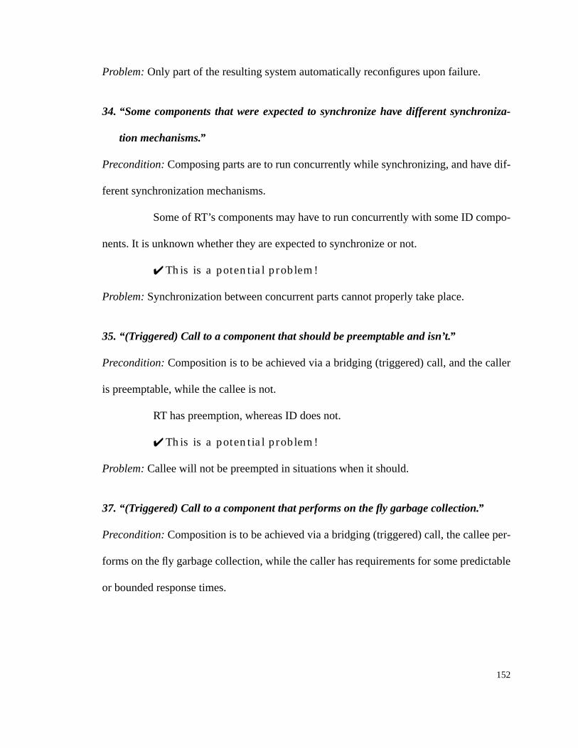
152
Problem: Only part of the resulting system automatically reconfigures upon failure.
34. “Some components that were expected to synchronize have different synchroniza-
tion mechanisms.”
Precondition: Composing parts are to run concurrently while synchronizing, and have dif-
ferent synchronization mechanisms.
Some of RT’s components may have to run concurrently with some ID compo-
nents. It is unknown whether they are expected to synchronize or not.
✔ This is a potential problem!
Problem:Synchronization between concurrent parts cannot properly take place.
35. “(Triggered) Call to a component that should be preemptable and isn’t.”
Precondition: Composition is to be achieved via a bridging (triggered) call, and the caller
is preemptable, while the callee is not.
RT has preemption, whereas ID does not.
✔ This is a potential problem!
Problem: Callee will not be preempted in situations when it should.
37. “(Triggered) Call to a component that performs on the fly garbage collection.”
Precondition: Composition is to be achieved via a bridging (triggered) call, the callee per-
forms on the fly garbage collection, while the caller has requirements for some predictable
or bounded response times.

153
ID performs on the fly garbage collection, and RT has predictable response
time requirements.
✔ This is a potential problem!
Problem: Undesirable side effects on the overall predictable or bounded response times.
40. “Time represented/compared using different granularities.”
Precondition: More than one of the composing parts has response time different than
unbound and cyclic unbound. Additionally, they are distributed over machines that repre-
sent and/or compare time using different granularities.
ID has response time unbound.
✘ This is not a potential problem!
Problem: Communications concerning time cannot properly occur.
41. “Absolute time values are off.”
Precondition: More than one of the composing parts has response time different than
unbound and cyclic unbound. Additionally, they are distributed over machines that have
their wall-clock time off.
ID has response time unbound.
✘ This is not a potential problem!
Problem: Communications concerning time cannot properly occur.
47. “Distributed control units are present.”
Precondition: Two or more of the composing subsystems have distributed control units.

154
RT has a central control unit, and ID has no control unit.
✘ This is not a potential problem!
Problem: Incorrect assumption that a problem is being solved elsewhere, by some other
control unit.
8.2 The AAA Model
If detailed and precise results are required, analysis can be performed at the
model level. The actual steps involved in applying our framework through the model are
as follows:
1. Describe the various parts to be composed in terms of base elements using Z and
the infrastructure we created.
2. Determine which kinds of connectors do occur during composition. There may be
more than one.
3. For the expected resulting system, including each of the parts to be composed and
the given connectors, manually trace the group and check_for_mismatches Z oper-
ations.
This should be a very tedious, long and error prone operation, but yield very
precise results.
We will not furnish an example of performing this kind of analysis because of
the unlikelihood of this being ever attempted elsewhere.

155
8.3 The AAA Tool
We created a Java tool called AAA that performs mismatch analysis on high
level descriptions of systems built by composition. These systems are described as a com-
position of subsystems with the corresponding bridging connectors. Subsystems can be
described in terms of features and/or styles. The tool also allows users to define their own
styles.
To illustrate the tool usage, we will show here in detail how it would handle the
composition of a subsystem based on the blackboard style with another based on the real-
time one. Results of composing a subsystem based on the real-time style with subsystems
based on all other styles are shown in appendix E.
1. The user must first create or open an existing project.
This is achieved by selecting either the New or the Open options of the Project
menu (figure 7).
Creating a project will create the file structure needed to store all the project
related information, as well as an initial set of styles (the ones described in section 4.0).
Opening a project will read all pre-existing project information from the avail-
able files.
Figure 7: AAA - Project Menu

156
For our example we will create a new project called RTwithOthers (figure 8).
2. The user may then define new style(s) as needed.
This is achieved by selecting the Style option in the Artifact menu (figure 9),
and then clicking on New at the Style’s List window (figure 10).
The user is then asked to enter the new style name, that must be unique within
the project (figure 11).
Figure 8: AAA - Project | New
Figure 9: AAA - Artifacts Menu
Figure 11: AAA - NewName

157
Subsequently the user may set the appropriate values for the various features in
the Style window. As seen on figure 12, the user is given the option of either saving or can-
celing this work.
For modifying pre-existing files the user would select the style name from the
given style’s list (figure 10), click on Ok, and change the feature values just as described
above.
Our example will use no newly defined styles.
3. The user must then define the subsystems that are to be composed.
This can be done based on features or on the styles defined.
Subsystems definition follows the same pattern as that of the styles. The user
selects Artifacts | Subsystems, gets prompted with a list of subsystems, clicks on New, and
enters a unique name. These actions result in the display of the subsystem window.
Figure 10: AAA - Styles’ List

158
For our example we will create a subsystem based on each and every one of the
styles provided. We shoe here the creation of RTsub, a subsystem based on the real-time
style (figure 13).
If defining subsystems based on a specific style, the styles choices for particu-
lar features are inherited. All features that were “unconstrained” for the style are shown as
“unknown” for the subsystem. It is up to the user to reflect the specific choice made by the
subsystem being described. All features left as “unknown” will be treated as taking any of
the possible values during mismatch analysis.
Figure 12: AAA - Style

159
RTsub is based on the real-time style, so we define it accordingly by choosing
real-time from the style’s list provided in the pull-down menu.
This automatically sets RTsub’s features accordingly. Since we are not dealing
with a specific subsystem, we will leave the “unknown” features unchanged (figure 14-
figure 27) .
When defining subsystems based on features the user must then set each and
every feature to reflect the specific situation.
Figure 13: AAA - Subsystem
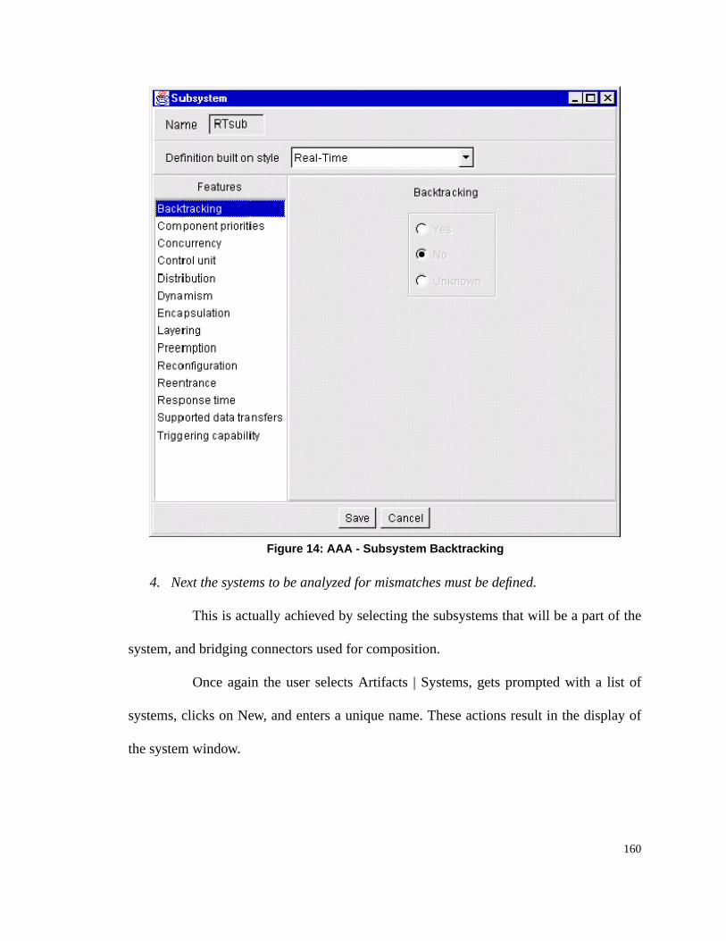
160
4. Next the systems to be analyzed for mismatches must be defined.
This is actually achieved by selecting the subsystems that will be a part of the
system, and bridging connectors used for composition.
Once again the user selects Artifacts | Systems, gets prompted with a list of
systems, clicks on New, and enters a unique name. These actions result in the display of
the system window.
Figure 14: AAA - Subsystem Backtracking

161
For our example we will create systems showing the composition of RTsub
with all other subsystems, one at a time. We show here the creation of RTwithBB, a system
that combines RTsub (based on the real-time style) with BBsub (based on the blackboard
style) (figure 28).
Once the system window comes up, the user must then select the relevant sub-
systems, in this case RTsub and BBsub (figure 29).
Figure 15: AAA - Subsystem Component Priorities

162
By doing so it creates a list of all pairs of chosen subsystems so that the user
can define the bridging connectors between them (if any).
For our example we will select all possible connections (figure 30).
5. Invoke the AAA engine to analyze for mismatches.
This is done by selecting the AAA Mismatch Analysis option of the Tools
menu (figure 31 on page 163), and then choosing the specific system to be analyzed from
Figure 16: AAA - Subsystem Concurrency

163
the given list (figure 32 on page 177). This invokes the AAA mismatch analysis engine,
that in turn will perform the analysis, save and display the results.
For our example we will show the selection of RTwithBB.
6. Review the analysis results.
Figure 17: AAA - Subsystem Control Unit
Figure 31: AAA - Tools Menu
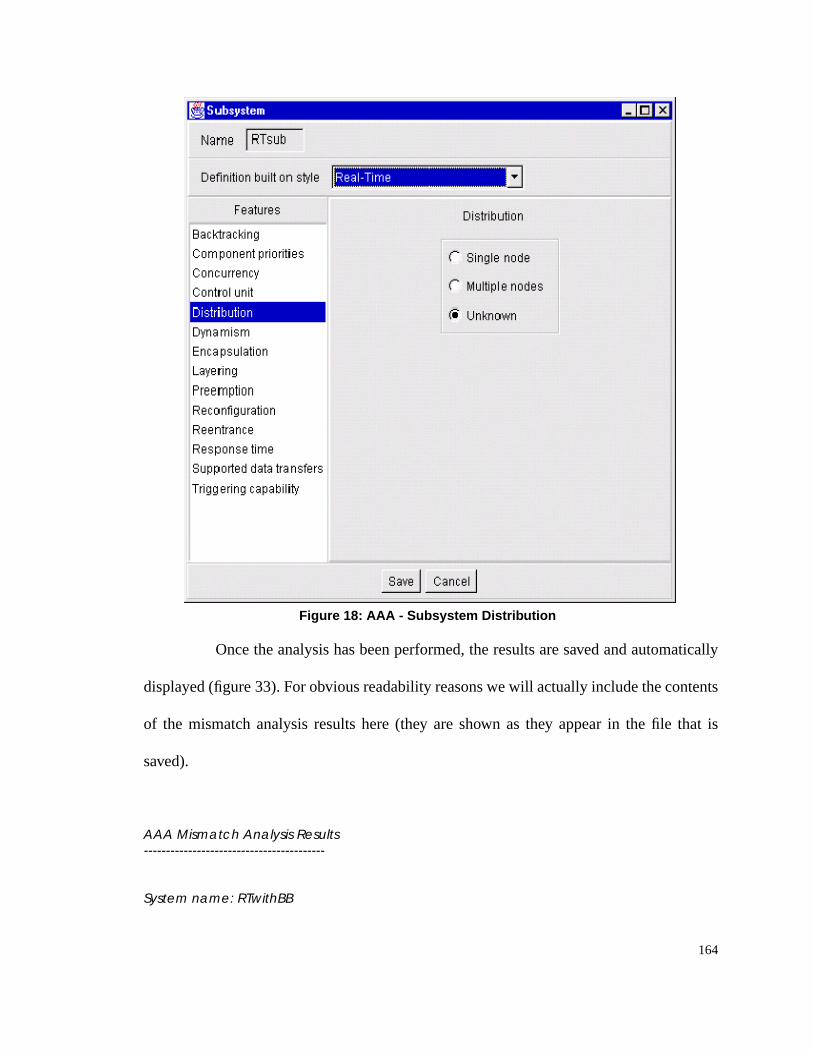
164
Once the analysis has been performed, the results are saved and automatically
displayed (figure 33). For obvious readability reasons we will actually include the contents
of the mismatch analysis results here (they are shown as they appear in the file that is
saved).
AAA Mismatch Analysis Results-----------------------------------------
System name: RTwithBB
Figure 18: AAA - Subsystem Distribution

165
Date: 9/3/98Time: 12:49:57
Mismatches:
Short descriptionTwo concurrent threads share data, with potential synchronization problems.
ProblemPotential synchronization problems for concurrent threads while sharing data.
Violating subsystemsRTsub and BBsub
-----------------------------------------
Figure 19: AAA - Subsystem Dynamism

166
Short descriptionA layering constraint is violated.
ProblemBridging connector may ignore existing layering constraints
Violating subsystemsRTsub (control layering unknown) and BBsub (control layering unknown) (on control layer)RTsub (data layering unknown) and BBsub (data layering unknown) (on data layer)
-----------------------------------------
Short descriptionDifferent sets of recognized events are used by two subsystems that permit triggers.
ProblemA trigger may not be recognized by some subsystem that should.
Violating subsystemsRTsub, BBsub
Figure 20: AAA - Subsystem Encapsulation

167
-----------------------------------------
Short descriptionA (triggered) spawn is made into or out of a subsystem which originally forbade them.
ProblemMay cause synchronization problems, as well as resources contention.
Violating subsystemsRTsub and BBsub (threads initiating unknown)
-----------------------------------------
Short descriptionAn unrecognized triggering event is used.
Problem
Figure 21: AAA - Subsystem Layering

168
The trigger will not cause the expected behavior, it will never fire the related actions.
Violating subsystemsRTsub and BBsubBBsub and RTsub
-----------------------------------------
Short descriptionA data connector is made into a subsystem which originally forbade them.
ProblemUnclear on how data is to be handled for sending or receiving.
Violating subsystemsRTsub and BBsub
-----------------------------------------
Figure 22: AAA - Subsystem Preemption

169
Short descriptionA shared data relationship refers to a subsystem which originally forbade them.
ProblemMay cause synchronization problems.
Violating subsystemsRTsub and BBsub
-----------------------------------------
Short descriptionA (triggered) spawn is made into or out of a subsystem which is not concurrent.
Problem
Figure 23: AAA - Subsystem Reconfiguration

170
May cause synchronization problems, as well as resources contention.
Violating subsystemsRTsub and BBsub (concurrency unknown)
-----------------------------------------
Short descriptionA node resource is overused.
ProblemResource overusage such as memory and disk space.
Violating subsystemsRTsub, BBsub
Figure 24: AAA - Subsystem Reentrance

171
-----------------------------------------
Short descriptionThere is a non-deterministic set of actions that could be caused by a trigger.
ProblemIt is not clear which set of actions should actually occur based on the composition, andif all, it is not clear what the ordering should be.
Violating subsystemsRTsub, BBsub
-----------------------------------------
Short descriptionData connectors connecting control components that are not always active may lead
Figure 25: AAA - Subsystem Response Time

172
into deadlock.
ProblemPossibility of deadlock on the control component sending the data.
Violating subsystemsRTsub and BBsub
-----------------------------------------
Short descriptionData connectors connecting control components that are not always active.
ProblemPossibility of loss of data.
Figure 26: AAA - Subsystem Supported Data Transfers

173
Violating subsystemsRTsub and BBsub
-----------------------------------------
Short descriptionErroneous assumption of single threaded.
ProblemSynchronization problems on accessing shared data, and/or resource contention.
Violating subsystemsRTsub and BBsub (concurrency unknown)
-----------------------------------------
Figure 27: AAA - Subsystem Triggering Capability

174
Short description(Triggered) Call to a cyclic (non-terminating) subsystem.
ProblemControl will never return to the caller.
Violating subsystemsRTsub and BBsub (response time unknown)
-----------------------------------------
Short descriptionErroneous assumption of same underlying platform.
ProblemCannot force fit parts to a given platform.
Violating subsystems
Figure 28: AAA - System

175
RTsub, BBsub
-----------------------------------------
Short description(Triggered) Call to a private method.
ProblemMethod not accessible to the caller.
Violating subsystemsRTsub and BBsub (encapsulation unknown)BBsub and RTsub (encapsulation unknown)
-----------------------------------------
Short description(Triggered) Spawn to a private method.
Problem
Figure 29: AAA - System Subsystems

176
Method not accessible to the spawner.
Violating subsystemsRTsub and BBsub (encapsulation unknown)BBsub and RTsub (encapsulation unknown)
-----------------------------------------
Short descriptionSharing private data.
ProblemData may not be accessible to all of the sharing entities being composed.
Violating subsystems
Figure 30: AAA - System and Connections
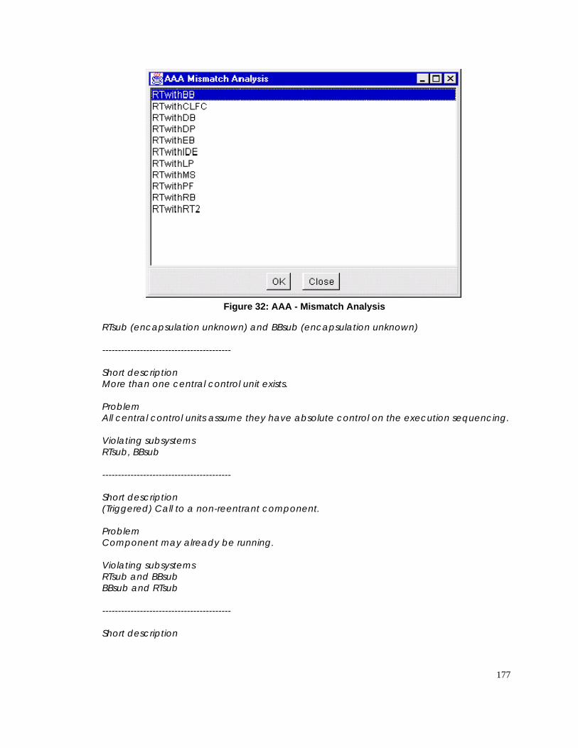
177
RTsub (encapsulation unknown) and BBsub (encapsulation unknown)
-----------------------------------------
Short descriptionMore than one central control unit exists.
ProblemAll central control units assume they have absolute control on the execution sequencing.
Violating subsystemsRTsub, BBsub
-----------------------------------------
Short description(Triggered) Call to a non-reentrant component.
ProblemComponent may already be running.
Violating subsystemsRTsub and BBsubBBsub and RTsub
-----------------------------------------
Short description
Figure 32: AAA - Mismatch Analysis

178
(Triggered) Spawn to a non-reentrant component.
ProblemComponent may already be running.
Violating subsystemsRTsub and BBsubBBsub and RTsub
-----------------------------------------
Short descriptionComposition involves one or more prioritized parts.
ProblemNot clear where a component(s) with or without an associated priority fits in an overallseparately prioritized structure.
Figure 33: AAA - Mismatch Analysis Results

179
Violating subsystemsRTsub, BBsub
-----------------------------------------
Short descriptionA prioritized system sharing a machine with some other system.
ProblemUnclear on how priorities compare across the various parts, which affects the wayinterrupts are to be applied.
Violating subsystemsRTsub
-----------------------------------------
Short description(Triggered) Call or spawn from a subsystem that may later backtrack.
ProblemWhile backtracking may cause undesired side effects on the called/spawned end.
Violating subsystemsBBsub and RTsub
-----------------------------------------
Short descriptionData being transferred from some component(s) that may later backtrack.
ProblemBacktracking may cause undesired side effects on the overall composed system state.
Violating subsystemsRTsub and BBsub
-----------------------------------------
Short descriptionSharing data with some component(s) that may later backtrack.
ProblemBacktracking may cause undesired side effects on the overall composed system state.
Violating subsystemsRTsub and BBsub
-----------------------------------------
Short description

180
(Triggered) Call from a subsystem requiring some predictable response times to somecomponent(s) no originally considered.
ProblemUnexpected side effects on original predicted response times may occur.
Violating subsystemsRTsub and BBsubBBsub (response times unknown) and RTsub
-----------------------------------------
Short description(Triggered) Spawn to or from a subsystem requiring some predictable response times tosome component(s) no originally considered.
ProblemMay have side effects on original predicted response times. The original predictedresponse times did not account for concurrently executing with these other components.
Violating subsystemsRTsub and BBsub
-----------------------------------------
Short descriptionOnly part of the resulting system automatically reconfigures upon failure.
ProblemOnly part of the resulting system automatically reconfigures upon failure.
Violating subsystemsReconfiguration unknown: RTsub, BBsub
-----------------------------------------
Short descriptionSome components that were expected to synchronize have different synchronizationmechanisms.
ProblemSynchronization between concurrent parts cannot properly take place.
Violating subsystemsRTsub and BBsub (concurrency unknown)
-----------------------------------------
Short description(Triggered) Call to a component that should be preemptable and isn't.

181
ProblemCallee will not be preempted in situations when it should.
Violating subsystemsRTsub and BBsub
-----------------------------------------
Short description(Triggered) Spawn to a component that should be preemptable and isn't.
ProblemSpawnee will not be preempted in situations when it should.
Violating subsystemsRTsub and BBsub
-----------------------------------------
Short description(Triggered) Call to a component that performs on the fly garbage collection.
ProblemUndesirable side effects on the overall predictable response times.
Violating subsystemsRTsub and BBsub (on the fly garbage collection unknown)
-----------------------------------------
Short descriptionIncorrect assumption of which instantiation of an object is either sending or receiving adata transfer.
ProblemIncorrect assumption of which instantiation of an object is either sending or receiving adata transfer.
Violating subsystemsRTsub (encapsulation unknown) and BBsub (encapsulation unknown)
-----------------------------------------
Short descriptionSharing data with the incorrect instantiation of an object.
ProblemSharing data with the incorrect instantiation of an object.
Violating subsystemsRTsub (encapsulation unknown) and BBsub (encapsulation unknown)

182
-----------------------------------------
Short descriptionSharing or transferring data with differing underlying representations.
ProblemCommunications concerning the specific data will not properly occur.
Violating subsystemsRTsub and BBsub
-----------------------------------------
Short descriptionResource contention.
ProblemPredictable response time indirectly affected because there may be some resourcecontention not originally considered.
Violating subsystemsRTsub, BBsub
-----------------------------------------
Short descriptionPotential database and/or DBMS heterogeneity problems may occur.
ProblemProblems may arise on semantic heterogeneity, differing data items granularity,databases being distributed or not, databases being replicated or not, and/ordatabases having different structural organizations.
Violating subsystemsBBsub, RTsub (shared repository unknown)
-----------------------------------------
Short descriptionInaccessible shared data.
ProblemApplets have no access to the local file system of the client side (i.e., the applet cannotreally access the data that is to be shared).
Violating subsystemsRTsub and BBsub (downloadable applets unknown)
-----------------------------------------

183
If the user wishes to review these results later on, he/she may do so by select-
ing the Mismatches Analysis Results under the Artifacts menu, and then choosing the spe-
cific system name from the given list (figure 34).
The results of similar analysis for all other systems defined can be found in
appendix E.
8.3.1 Miscellaneous
The tool allows for the definition of more than one system within a project.
This is provided to support user experimentation with more than one combination of sub-
systems, permitting different subsystems to be chosen each time, as well as variations on
the bridging connectors used.
Figure 34: AAA - Mismatch Analysis Results’ List

184
The tool allows for the modification of any user defined information, and shall
soon allow for their deletion as well. No printing means have been provided yet, but this
may be achieved by printing the individual text files.

185

185
Part IV: Conclusion
The following sections conclude this document by summarizing the key contri-
butions made by this work, and by introducing future directions to be taken.

186

186
9.0 Summary of Key Contributions
Below is a list of some of the key contributions of this work.
• Providing support for mismatch detection during systems composition, be it homoge-
neous, heterogeneous, based on conceptual features or on styles.
• Showing that Abd-Allah was correct in assuming that using conceptual features for
mismatch detection was an extensible framework, though it did require a considerable
amount of evolution of the framework to do so.
• Demonstrating that the hypothesis about the sufficiency of Abd-Allah’s conceptual
feature set for system’s description was false, as was the hypothesis about the com-
pleteness of his architectural mismatches set.
• Determining a strong set of conceptual features required for effectively describing and
comparing architectural styles, as well as systems.
• Providing initial structuring of the space of conceptual features, providing some initial
insight to a more formal foundation for the model, as well as guidelines on how to
evolve it.
• Extending the model of architectural styles, broadening the AAA model for a more
complete style coverage.
• Providing a comprehensive set of mismatches with explanations on preconditions and
problems inferred by each one of them.
• Defining a model of systems composition based on the styles’ models mentioned
above, and checking for the full set of mismatches covered.

187
• Developing a fully operational tool based on the above mentioned models, to
be used for analyzing various systems compositions for architectural mis-
matches.

188
10.0 Future Directions
This section suggests some directions that could be pursued in the long term
based on the results obtained here.
• Apply the approach to a set of real problems, and analyze its effectiveness.
• Extend the study of the conceptual feature space.
• Provide for import/export from the AAA tool notation to ACME.
• Study the existent ADLs in order to evaluate and classify them according to the vari-
ous dimensions of the conceptual feature space, as well as the conceptual feature set.
• Reflect additional architectural views such as cost, performance, and reliability.
• Propose solutions to the identified mismatches.
• Look into reverse engineering for retrieving the information needed for mismatch
analysis.
• Create a catalog of various COTS and GOTS tools for the AAA tool to incorporate.
• Investigate quality related architectural attributes, and how they impact systems com-
position.
• Provide means of simulating the effects of the control and data transfer Z operations.

189

189
Part V: Bibliography and Appendices
The bibliography used for this work is given, as well as appendices describing
the formal notation used earlier, the complete AAA Z model generated by Abd-Allah
[Abd-Allah 1996], our complete AAA Z model, and some time related classification of
systems and operations. There is also an appendix covering the mismatches to be expected
when composing real-time systems with systems in any of the styles discussed in this
work, and another defining the various acronyms used throughout this work.

190

190
11.0 Bibliography
[Abd-Allah 1996] A. Abd-Allah,Composing Heterogeneous Software Architectures, Doc-toral Dissertation, Center for Software Engineering, University of Southern California,August 1996 (http://sunset.usc.edu/TechRpts/dissertation.html).
[Allen and Garlan 1994] R. Allen and D. Garlan, “Formalizing Architectural Connection,”in Proceedings of the 16th International Conference on Software Engineering, IEEE Com-puter Society Press, Sorrento, Italy, May 1994, pp. 71-80.
[Allan and Garlan 1996] R. Allen and D. Garlan,The Wright Architectural SpecificationLanguage, 24 September 1996 (http://www.cs.cmu.edu/afs/cs/project/able/ftp/wright-tr.ps).
[Bihari and Gopinath 1992] T. E. Bihari and P. Gopinath, “Object-Oriented Real-TimeSystems: Concepts and Examples,”Computer, December 1992, pp. 25-32.
[Boehm and Scherlis 1992] B. W. Boehm and W. L. Scherlis, “Megaprogramming,”Pro-ceedings of the DARPA Software Technology Conference, April 1992 (available via USCCenter for Software Engineering, Los Angeles, CA, 90089-0781).
[Clocksin and Mellish 1987] W. F. Clocksin and C. S. Mellish, Programming in Prolog,third edition, Springer-Verlag, 1987.
[Curtis 1997] D. Curtis,Java, RMI, and CORBA, white paper, Object Management Group(OMG), 1997 (http://www.omg.org/news/wpjava.htm).
[December and Ginsburg 1995] J. December and M. Ginsburg, HTML & CGI Unleashed,Sams.net Publishin, 1995.
[Downing 1998] T. B. Downing, Java Rmi : Remote Method Invocation, IDG BooksWorldwide, 1998.
[Elmasri and Navathe 1989] R. Elmasri and S. B. Navathe, Fundamentals of DatabaseSystems, Benjamin/Cunnings Publishing, 1989.
[Fiddler 1994] J. Fiddler, “Hard Real-Time vs. Soft Real-Time,”UNIX Review, April1994, pp. 47.
[Gacek 1995] C. Gacek, “Exploiting Domain Architectures in Software Reuse,” inPro-ceedings of the ACM-SIGSOFT Symposium on Software Reusability (SSR’95),ACMPress, Seattle, Wa., 28-30 April 1995, pp. 229-232.

191
[Gacek et al. 1995] C. Gacek, A. Abd-Allah, B. Clark, and B. Boehm, “On the Definitionof Software Architecture,” inProceedings of the First International Workshop on Archi-tectures for Software Systems - In Cooperation with the 17th International Conference onSoftware Engineering, D. Garlan (ed.), Seattle, Wa., 24-25 April 1995, pp. 85-95.
[Garlan 1995] D. Garlan,An Introduction to the Aesop System, Carnegie Mellon Univer-sity, 11 July 1995 (http://www.cs.cmu.edu/afs/cs/project/able/www/aesop/html/aesop-overview.ps).
[Garlan et al. 1995a] D. Garlan, R. Allen, and J. Ockerbloom, “Architectural Mismatch orWhy it’s hard to build systems out of existing parts,”IEEE Software, November 1995, pp.17-26.
[Garlan et al. 1995b] D. Garlan, R. Monroe, and D. Wile,ACME: An Architectural Inter-change Language, Technical Report CMU-CS-95-219, Carnegie Mellon University,November 1995.
[Garlan et al. 1997] D. Garlan, R. Monroe, and D. Wile,ACME: An Architecture Descrip-tion Interchange Language, white paper, Carnegie Mellon University, 14 January 1997(http://www.cs.cmu.edu/afs/cs/project/able/ftp/acme-esec97.ps).
[Genesereth and Ginsberg 1985] M. Genesereth and M. Ginsberg, “Logic Programming,”Communications of the ACM, vol. 28, no. 9, September 1985, pp. 933-941.
[Gomaa 1993] H. Gomaa, Software Design Methods for Concurrent and Real-Time Sys-tems, Addison-Wesley Publishing Company, Inc., 1993.
[Hammer and McLeod 1993] J. Hammer and D. McLeod, “An Approach to ResolvingSemantic Heterogeneity in a Federation of Autonomous, Heterogeneous Database Sys-tems,” International Journal of Intelligent & Cooperative Information Systems, M. Papa-zoglou and T. Sellis (ed.), World Scientific, vol. 2, no. 1, 1993, pp. 51-83.
[Hayes-Roth 1985] F. Hayes-Roth, “Rule-Based Systems,”Communications of the ACM,vol. 28, no. 9, September 1985, pp. 921-932.
[Heimbigner and McLeod 1985] D. Heimbigner and D. McLeod, “A Federated Architec-ture for Information Management,”ACM Transactions on Office Information Systems, vol.3, no. 3, July 1985, pp. 253-278.
[Jia 1994] X. Jia, “ZTC: A Type Checker for Z User’s Guide,” Department of ComputerScience, DePaul University, 1994.

192
[Kazman et al. 1997] R. Kazman, P. Clements, G. Abowd, and L. Bass, “ClassifyingArchitectural Elements as a Foundation for Mechanism Matching,” to appear inProceed-ings of COMPSAC 1997,Washington, DC, August 1997.
[Kogut and Creps 1998] P. Kogut and R. Creps, “CORBA-Aware Environments,” inPro-ceedings of Lockheed Martin Systems Engineering and Software Symposium,NewOrleans, LA, May 13-15 1998.
[Kurki-Suonio 1993] R. Kurki-Suonio, “Stepwise Design of Real-Time Systems,”IEEETransactions on Software Engineering, vol. 19, no. 1, January 1993, pp. 56-69.
[Lee 1998] J. S. Lee,Designing and Building Protocols for Web Applications, draft ofDoctoral Dissertation, Center for Software Engineering, University of Southern Califor-nia, August 1998.
[Luckham 1996] D. Luckham, “Rapide: A Language and Toolset for Simulation of Dis-tributed Systems by Partial Orderings of Events,”DIMACS Partial Order Methods Work-shop IV,Princeton University, July 1996 (http://anna.stanford.edu/rapide/whats-new.html).
[Luckham and Vera 1995] D. Luckham and J. Vera, “An Event-Based Architecture Defini-tion Language,”IEEE Transactions on Software Engineering, vol. 21, no. 9, September1995, pp. 717-734.
[Magee and Kramer 1996] J. Magee and J. Kramer, “Dynamic Structure in SoftwareArchitectures,” inProceeding of the ACM SIGSOFT’96: Fourth Symposium on the Foun-dations of Software Engineering (FSE4), San Francisco, CA, October 1996, pp. 24-32.
[McIlroy 1969] M. D. McIlroy, “Mass Produced Software Components,”Software Engi-neering, NATO Science Committee, January 1969, pp. 138-155.
[Medvidovic 1997] N. Medvidovic,A Classification and Comparison Framework for Soft-ware Architecture Description Languages, Technical Report UCI-ICS-97-02, Departmentof Information and Computer Science, University of California, Irvine, CA, 92697-3425,February 1997.
[Medvidovic et al. 1996] N. Medvidovic, R. N. Taylor, and E. J. Whitehead, Jr., “FormalModeling of Software Architectures at Multiple Levels of Abstraction,” inProceedings ofthe California Software Symposium 1996, Los Angeles, CA, April 1996, pp. 28-40.
[MetaH 1996] ___,MetaH Language and Tools, 31 December 1996 (http://www.htc.hon-eywell.com/projects/dssa/dssa_tools/dssa_tools_mh.html).

193
[Monroe and Garlan 1996] R. Monroe and D. Garlan, “Style-Based Reuse for SoftwareArchitectures,” inProceedings of the Fourth International Conference on Software Reuse,Orlando, Fl., 23-26 April 1996.
[Monroe et al. 1997] R. T. Monroe, A. Kompanek, R. Melton, and D. Garlan, “Architec-tural Styles, Design Patterns, and Objects,”IEEE Software, January 1997, pp. 43-52.
[Moriconi and Riemenschneider 1997] M. Moriconi R. A. Riemenschneider,Introductionto SADL 1.0--A Language for Specifying Software Architecture Hierarchies, TechnicalReport SRI-CSL-97-01, Computer Science Laboratory, SRI International, March 1997(http://www.csl.sri.com/sadl/sadl-intro.ps.gz).
[Moriconi et al. 1995] M. Moriconi, X. Qian, and R. A. Riemenschneider, “Correct Archi-tecture Refinement,”IEEE Transactions on Software Engineering,vol. 21, no. 4, April1995, pp. 356-372.
[Nii 1986] H. Nii, “Blackboard Systems - Parts 1 and 2,”AI Magazine, vol. 7, no. 3 (pp.38-53), and no. 4 (pp. 62-69), 1986.
[Orfali et al. 1996] R. Orfali, D. Harkey, and J. Edwards, The Essential Client/Server Sur-vival Guide, John Wiley & Sons, Inc., 1996.
[Orfali et al. 1997] R. Orfali, D. Harkey, and J. Edwards, Instant CORBA, John Wiley &Sons, Inc., 1997.
[Perry and Wolf 1992] D. E. Perry and A. L. Wolf, “Foundations for the Study of SoftwareArchitecture,”ACM Software Engineering Notes, vol. 17. no. 4, October 1992, pp. 40-52.
[Prieto-Diaz and Freeman 1987] R. Prieto-Diaz and P. Freeman, “Classifying Software forReusability,”IEEE Software, January 1987, pp. 6-16.
[Pyle et al. 1993] I. Pyle, P. Hruschka, M. Lissandre and K. Jackson,Real-Time Systems--Investigating Industrial Practice, John Wiley & Sons Ltd., England, 1993.
[Radice and Phillips 1988] R. A. Radice and R. W. Phillips, Software Engineering--AnIndustrial Approach, vol. 1, Prentice Hall, 1988.
[Rapide 1996] ___,Guide to the Rapide 1.0 Language Reference Manuals, Stanford Uni-versity, 5 December 1996 (http://anna.stanford.edu/rapide/lrms/overview.ps).
[Rich and Knight 1991] E. Rich and K. Knight, Artificial Intelligence, second edition,McGraw-Hill, 1991.

194
[Ripps 1989] D. L. Ripps, An Implementation Guide to Real-Time Programming, YourdonPress, 1989.
[Shaw and Clements 1997] M. Shaw and P. Clements, “A Field Guide to Boxology: Pre-liminary Classification of Architectural Styles for Software Systems,” to appear inPro-ceedings of COMPSAC 1997,Washington, DC, August 1997 (http://www.cs.cmu.edu/afs/cs.cmu.edu/project/vit/www/paper_abstracts/Boxology.html)
[Shaw and Garlan 1996] M. Shaw and D. Garlan, Software Architectures--Perspectives onan Emerging Discipline, Prentice Hall, 1996.
[Shaw et al. 1995] M. Shaw, R. DeLine, D. V. Klein, T. L. Ross, D. M. Young, and G.Zelesnik, “Abstractions for Software Architecture and Tools to Support Them,”IEEETransactions on Software Engineering, vol. 21. no. 4, April 1995, pp. 314-335.
[Spivey 1992] J. Spivey, The Z Notation, Prentice Hall, 1992.
[Stankovic 1988] J. Stankovic, “Misconceptions About Real-Time Computing--A SeriousProblem for Next-Generation Systems,”Computer, October 1988, pp. 10-19.
[Stevens 1990] W. R. Stevens, UNIX Network Programming, Prentice Hall, 1990.
[Stiger and Gamble 1997] P. Stiger and R. Gamble, “Blackboard Systems Formalizedwithin a Software Architectural Style,” inProceedings of the 1997 International Confer-ence on Systems, Man, and Cybernetics, IEEE Computer Society Press, October 1997.
[Tracz 1994] W. Tracz, “Domain-Specific Software Architecture Frequently Asked Ques-tions,” ACM Software Engineering Notes, vol. 9. no. 2, April 1994, pp. 52-56.
[Vestal 1997] S. Vestal,MetaH Programmer’s Manual, Version 1.14,Technical ReportHoneywell Technology Center, 7 March 1997.
[Westphal 1995] L. Westphal, Sourcebook of Control Systems Engineering, Chapman &Hall, 1995.
[Zaremski and Wing 1993] A. M. Zaremski and J. M. Wing, “Signature Matching: A Keyto Reuse,”Proceedings of the First ACM SIGSOFT Symposium on the Foundations ofSoftware Engineering, December 1993, pp. 182-190.
[Zelesnik 1996] G. Zelesnik,The UniCon Language Reference Manual, Carnegie MellonUniversity, 13 May 1996 (http://www.cs.cmu.edu/~UniCon/reference-manual/Reference_Manual_1.html).

195