Embed Size (px)
Citation preview
8/20/2019 Detailing of Reinforcement in Concrete Structures 28 Aug 2012
http://slidepdf.com/reader/full/detailing-of-reinforcement-in-concrete-structures-28-aug-2012 1/82
THE CIVIL & STRUCTURAL ENGINEERING PANELTHE CIVIL & STRUCTURAL ENGINEERING PANEL
ENGINEERS AUSTRALIA SYDNEY DIVISIONENGINEERS AUSTRALIA SYDNEY DIVISION
28 August 2012
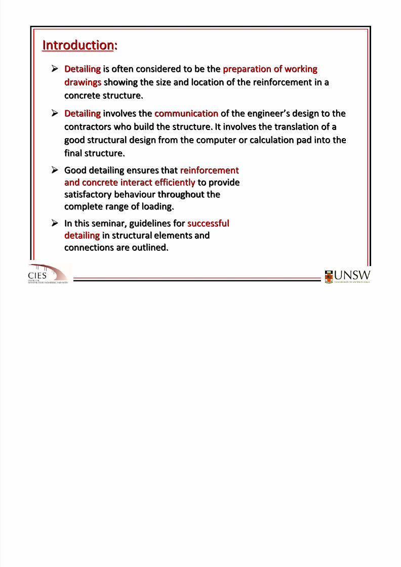
Detailing of ReinforcementDetailing of Reinforcement
in Concrete
Structuresin
Concrete
Structures
R.I. GilbertR.I. Gilbert
8/20/2019 Detailing of Reinforcement in Concrete Structures 28 Aug 2012
http://slidepdf.com/reader/full/detailing-of-reinforcement-in-concrete-structures-28-aug-2012 2/82
8/20/2019 Detailing of Reinforcement in Concrete Structures 28 Aug 2012
http://slidepdf.com/reader/full/detailing-of-reinforcement-in-concrete-structures-28-aug-2012 3/82
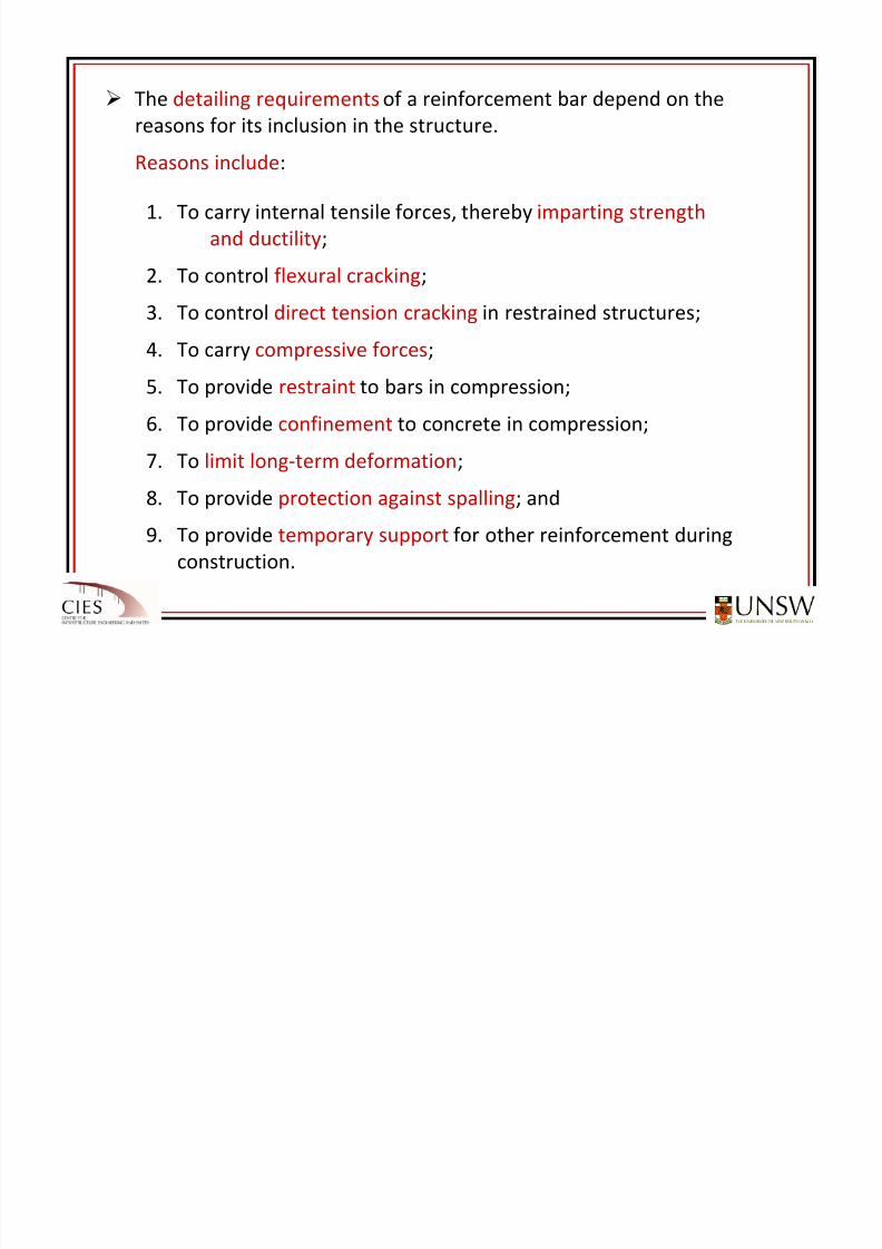
The detailing requirements of a reinforcement bar depend on the
reasons for
its
inclusion
in
the
structure.
Reasons include:
1. To carry internal tensile forces, thereby imparting strength
and ductility;
2. To control flexural cracking;
3. To control direct tension cracking in restrained structures;
4. To
carry
compressive
forces;5. To provide restraint to bars in compression;
6. To provide confinement to concrete in compression;
7. To limit long‐term deformation;
8. To provide protection against spalling; and
9. To provide temporary support for other reinforcement during
construction.
8/20/2019 Detailing of Reinforcement in Concrete Structures 28 Aug 2012
http://slidepdf.com/reader/full/detailing-of-reinforcement-in-concrete-structures-28-aug-2012 4/82
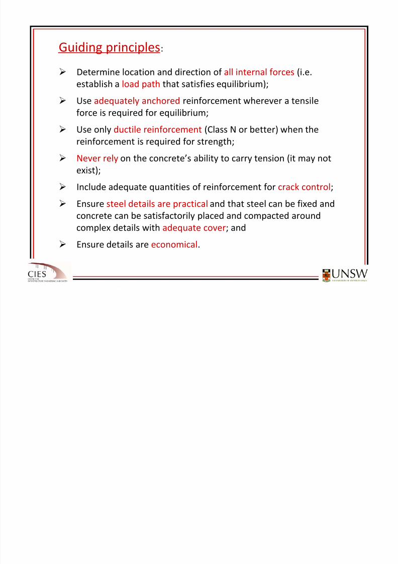
Guiding
principles:
Determine location and direction of all internal forces (i.e.
establish a load path that satisfies equilibrium);
Use adequately anchored reinforcement wherever a tensile
force is
required
for
equilibrium;
Use only ductile reinforcement (Class N or better) when the
reinforcement is required for strength;
Never rely on
the
concrete’s
ability
to
carry
tension
(it
may
not
exist);
Include adequate quantities of reinforcement for crack control;
Ensure steel details are practical and that steel can be fixed and
concrete can
be
satisfactorily
placed
and
compacted
around
complex details with adequate cover; and
Ensure details are economical.
8/20/2019 Detailing of Reinforcement in Concrete Structures 28 Aug 2012
http://slidepdf.com/reader/full/detailing-of-reinforcement-in-concrete-structures-28-aug-2012 5/82
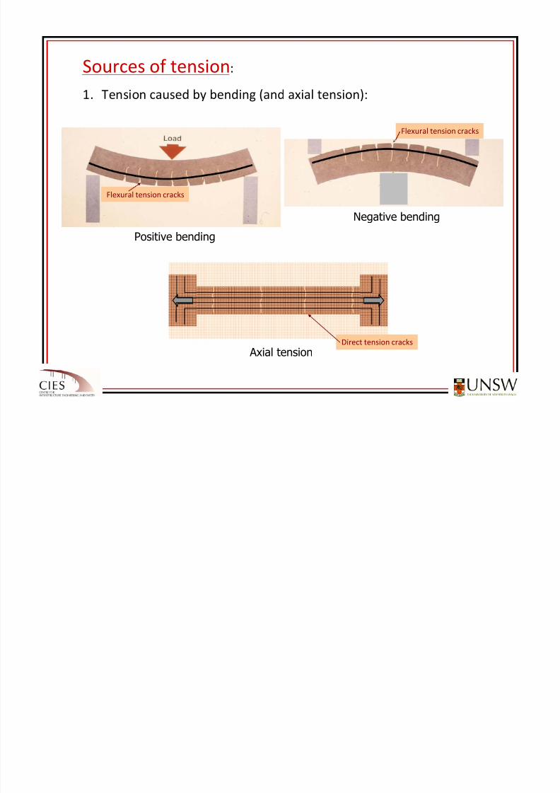
Sources
of
tension:
1. Tension caused by bending (and axial tension):
Positive bending
Negative bending
Axial tension
Flexural tension cracks
Flexural tension cracks
Direct tension cracks
8/20/2019 Detailing of Reinforcement in Concrete Structures 28 Aug 2012
http://slidepdf.com/reader/full/detailing-of-reinforcement-in-concrete-structures-28-aug-2012 6/82
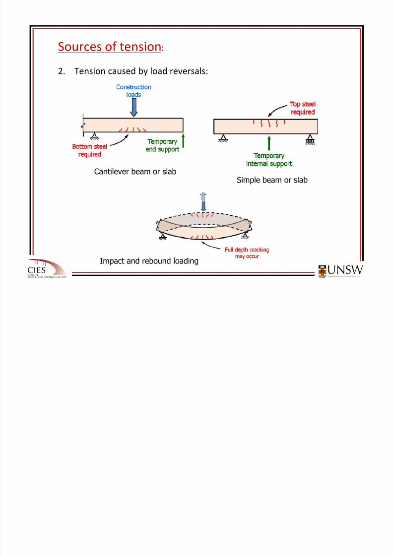
Sources of tension:
2. Tension caused by load reversals:
Cantilever beam or slabSimple beam or slab
Impact and rebound loading
8/20/2019 Detailing of Reinforcement in Concrete Structures 28 Aug 2012
http://slidepdf.com/reader/full/detailing-of-reinforcement-in-concrete-structures-28-aug-2012 7/82
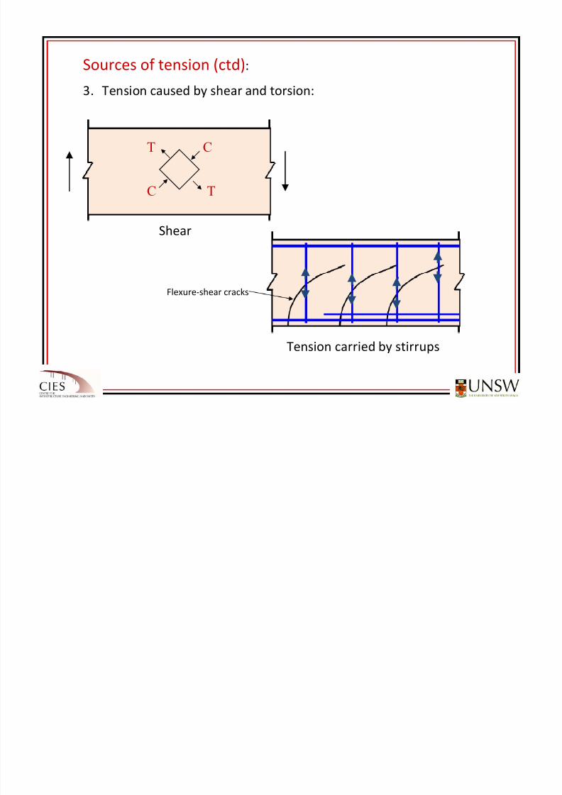
Sources of tension (ctd):
3. Tension caused by shear and torsion:
C
C T
T
Shear
Tension carried by stirrups
Flexure‐shear cracks
8/20/2019 Detailing of Reinforcement in Concrete Structures 28 Aug 2012
http://slidepdf.com/reader/full/detailing-of-reinforcement-in-concrete-structures-28-aug-2012 8/82
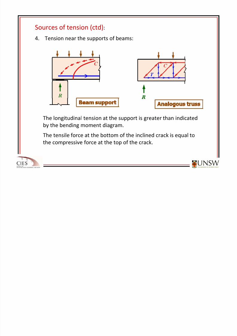
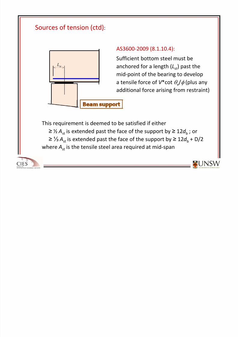
Sources of tension (ctd):
4. Tension near the supports of beams:
The longitudinal tension at the support is greater than indicated
by the bending moment diagram.
The tensile force at the bottom of the inclined crack is equal to
the compressive force at the top of the crack.
8/20/2019 Detailing of Reinforcement in Concrete Structures 28 Aug 2012
http://slidepdf.com/reader/full/detailing-of-reinforcement-in-concrete-structures-28-aug-2012 9/82
8/20/2019 Detailing of Reinforcement in Concrete Structures 28 Aug 2012
http://slidepdf.com/reader/full/detailing-of-reinforcement-in-concrete-structures-28-aug-2012 10/82
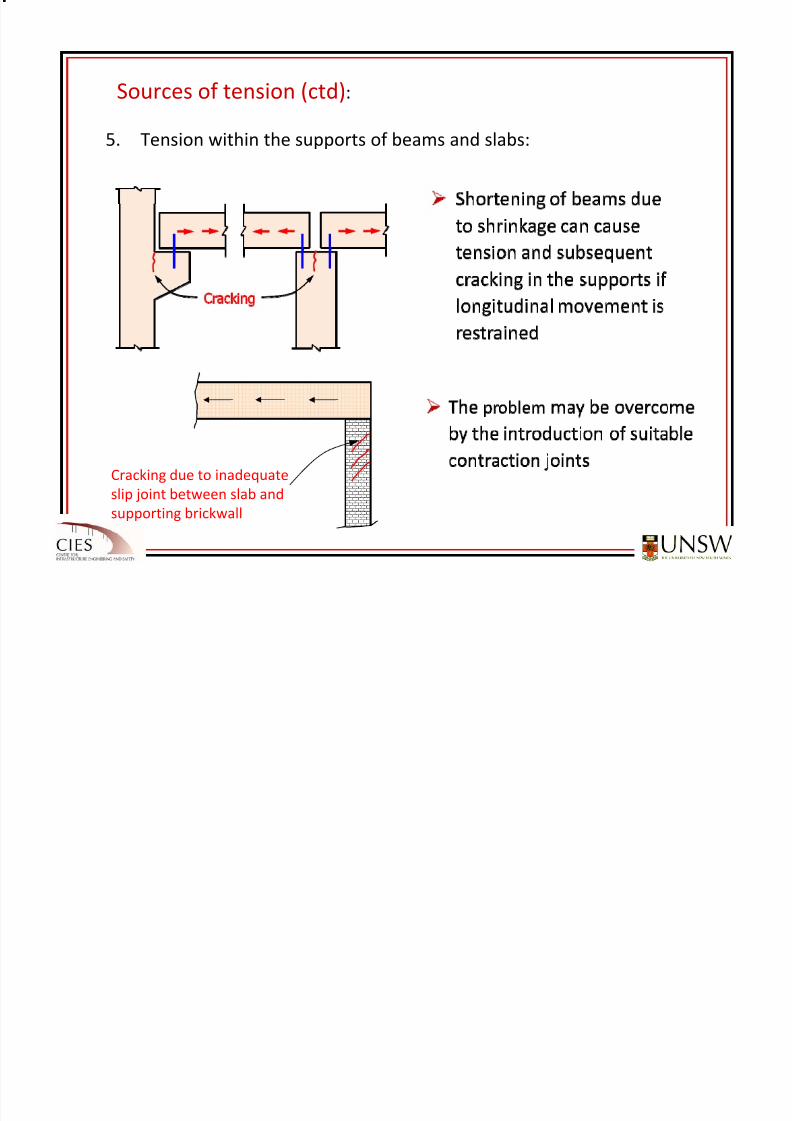
Sources of tension (ctd):
5. Tension within the supports of beams and slabs:
Cracking due to inadequate
slip joint between slab and
supporting brickwall
8/20/2019 Detailing of Reinforcement in Concrete Structures 28 Aug 2012
http://slidepdf.com/reader/full/detailing-of-reinforcement-in-concrete-structures-28-aug-2012 11/82
Sources of tension (ctd):
6. Tension within connections:
Hanger
reinf. to
carry
tension
Primary girder
Compression struts
Reaction from secondary beam
applied here
Secondary
beam
M
M
C
C
T
T
M
M
(a) Internal forces (b) Crack pattern
2 T
8/20/2019 Detailing of Reinforcement in Concrete Structures 28 Aug 2012
http://slidepdf.com/reader/full/detailing-of-reinforcement-in-concrete-structures-28-aug-2012 12/82
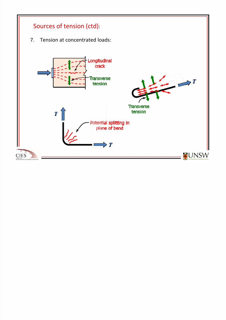
Sources of tension (ctd):
7. Tension at concentrated loads:
8/20/2019 Detailing of Reinforcement in Concrete Structures 28 Aug 2012
http://slidepdf.com/reader/full/detailing-of-reinforcement-in-concrete-structures-28-aug-2012 13/82
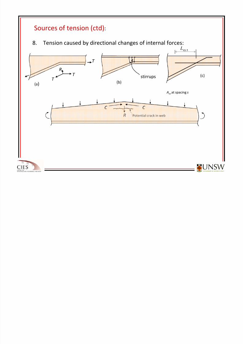
Sources of tension (ctd):
8. Tension caused by directional changes of internal forces:
(a)
T
T T
R
stirrups(b)
Lsy.t
(c)
C C
R Potential crack in web
Asv at spacing s
8/20/2019 Detailing of Reinforcement in Concrete Structures 28 Aug 2012
http://slidepdf.com/reader/full/detailing-of-reinforcement-in-concrete-structures-28-aug-2012 14/82
Sources of tension (ctd):
8. Tension caused by directional changes of internal forces:
(a)
T
T T
R
stirrups(b)
Lsy.t
(c)
Asv at spacing s
C
T
C
T
r m
qt
Ast
m
sy st
m
t r
f A
r
T q == m
sy
vy
st
sv
t
vy svr
f
f
A
A
q
f A s ..==
Transverse tension: Required stirrup spacing:
8/20/2019 Detailing of Reinforcement in Concrete Structures 28 Aug 2012
http://slidepdf.com/reader/full/detailing-of-reinforcement-in-concrete-structures-28-aug-2012 15/82
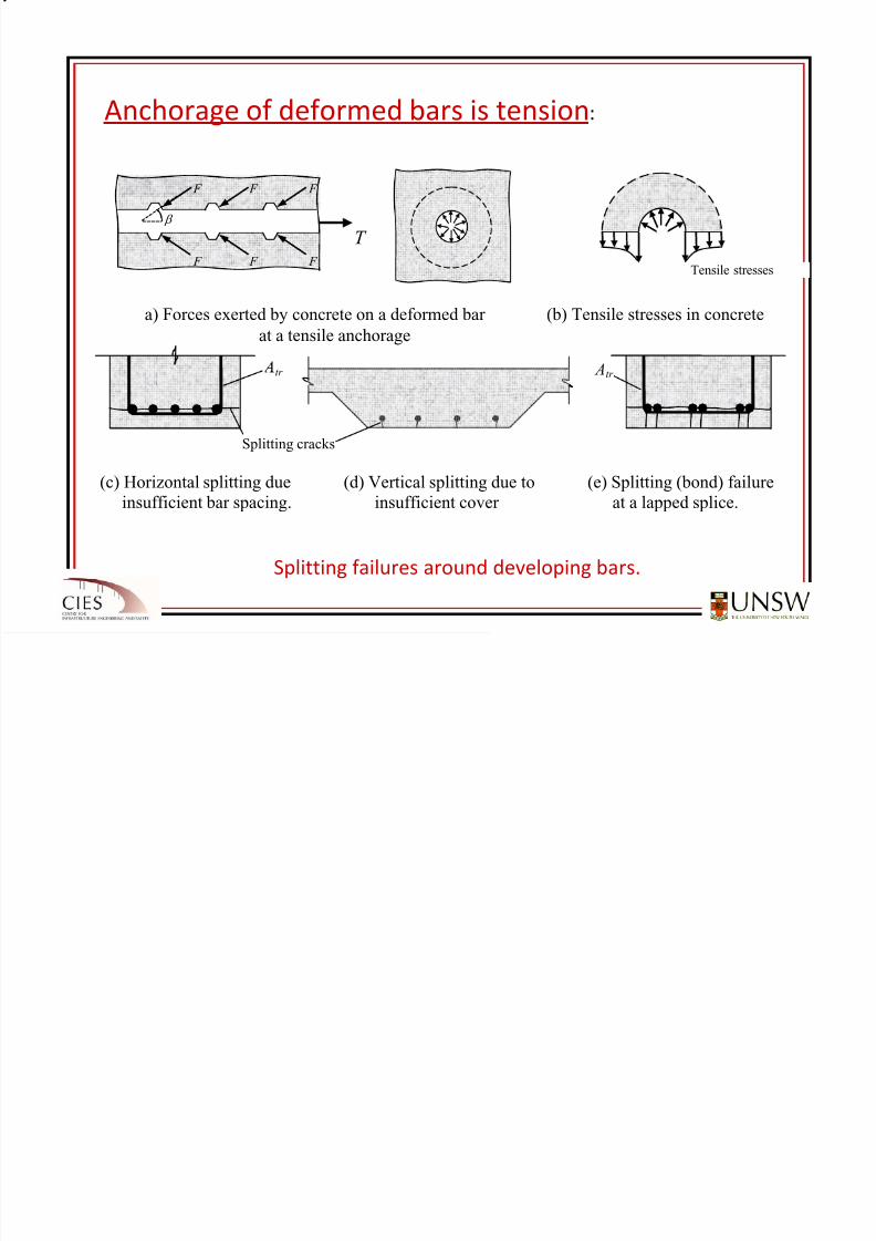
Splitting failures around developing bars.
F F F
β
T F F F
Tensile stresses
tr Atr
Splitting cracks
a) Forces exerted by concrete on a deformed bar (b) Tensile stresses in concrete
at a tensile anchorage
(c) Horizontal splitting due (d) Vertical splitting due to (e) Splitting (bond) failureinsufficient bar spacing. insufficient cover at a lapped splice.
Anchorage
of
deformed
bars
is
tension:
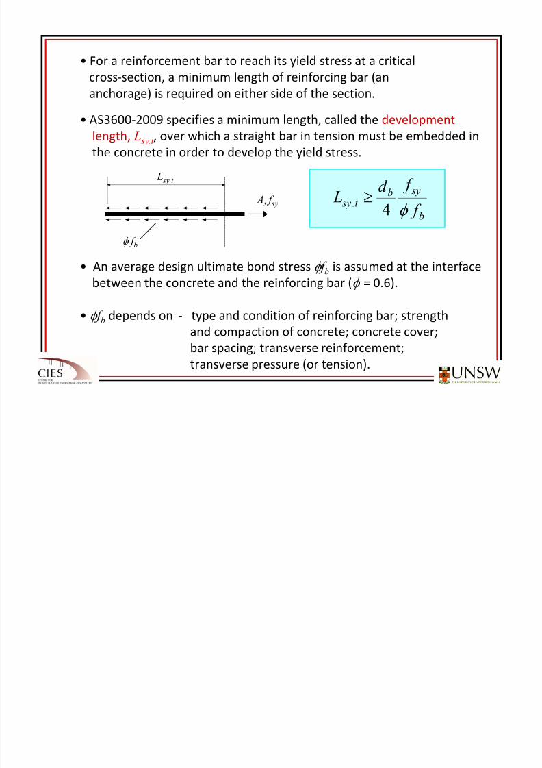
8/20/2019 Detailing of Reinforcement in Concrete Structures 28 Aug 2012
http://slidepdf.com/reader/full/detailing-of-reinforcement-in-concrete-structures-28-aug-2012 16/82
L sy.t
φ f b
A s f sy
b
sybt sy
f
f d L
φ 4. ≥
• For a reinforcement bar to reach its yield stress at a critical
cross‐section,
a minimum
length
of
reinforcing
bar
(an
anchorage) is required on either side of the section.
• AS3600‐2009 specifies a minimum length, called the development
length, L sy.t , over which a straight bar in tension must be embedded in
the concrete
in
order
to
develop
the
yield
stress.
• An average design ultimate bond stress φ f b is assumed at the interface
between the concrete and the reinforcing bar (φ = 0.6).
• φ f b depends on ‐ type and condition of reinforcing bar; strength
and compaction of concrete; concrete cover;
bar spacing; transverse reinforcement;
transverse pressure
(or
tension).
8/20/2019 Detailing of Reinforcement in Concrete Structures 28 Aug 2012
http://slidepdf.com/reader/full/detailing-of-reinforcement-in-concrete-structures-28-aug-2012 17/82
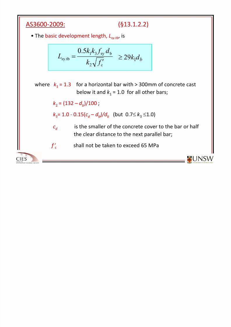
• The basic development length, Lsy.tb, is
where k 1 = 1.3 for a horizontal bar with > 300mm of concrete cast
below
it
and
k 1 =
1.0
for
all
other
bars;
k 2 = (132 – d b)/100 ;
k 3= 1.0 ‐ 0.15(cd – d b )/d b (but 0.7≤ k 3 ≤1.0)
cd is the
smaller
of
the
concrete
cover
to
the
bar
or
half
the clear distance to the next parallel bar;
f ′ c shall not be taken to exceed 65 MPa
AS3600‐2009: (§13.1.2.2)
bd k 129≥c2
bsy31
sy.tb
5.0
f k
d f k k L
′
=
8/20/2019 Detailing of Reinforcement in Concrete Structures 28 Aug 2012
http://slidepdf.com/reader/full/detailing-of-reinforcement-in-concrete-structures-28-aug-2012 18/82
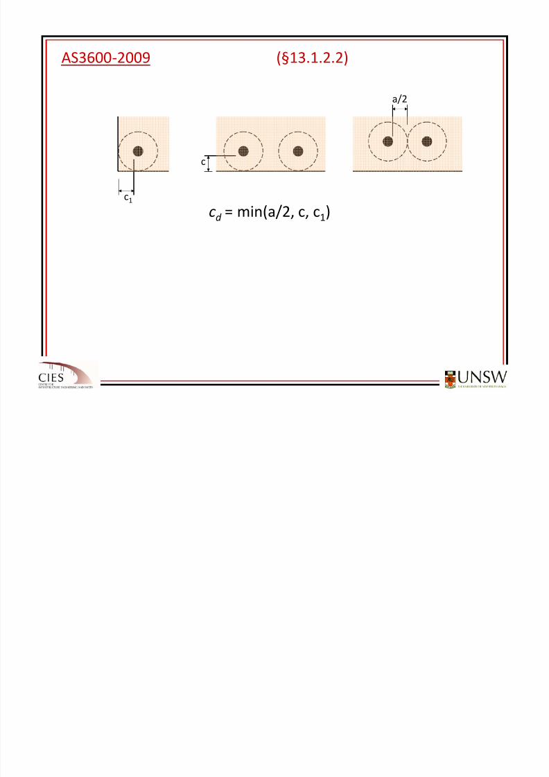
AS3600‐2009 (§13.1.2.2)
c1
c
a/2
cd = min(a/2, c, c1)
8/20/2019 Detailing of Reinforcement in Concrete Structures 28 Aug 2012
http://slidepdf.com/reader/full/detailing-of-reinforcement-in-concrete-structures-28-aug-2012 19/82
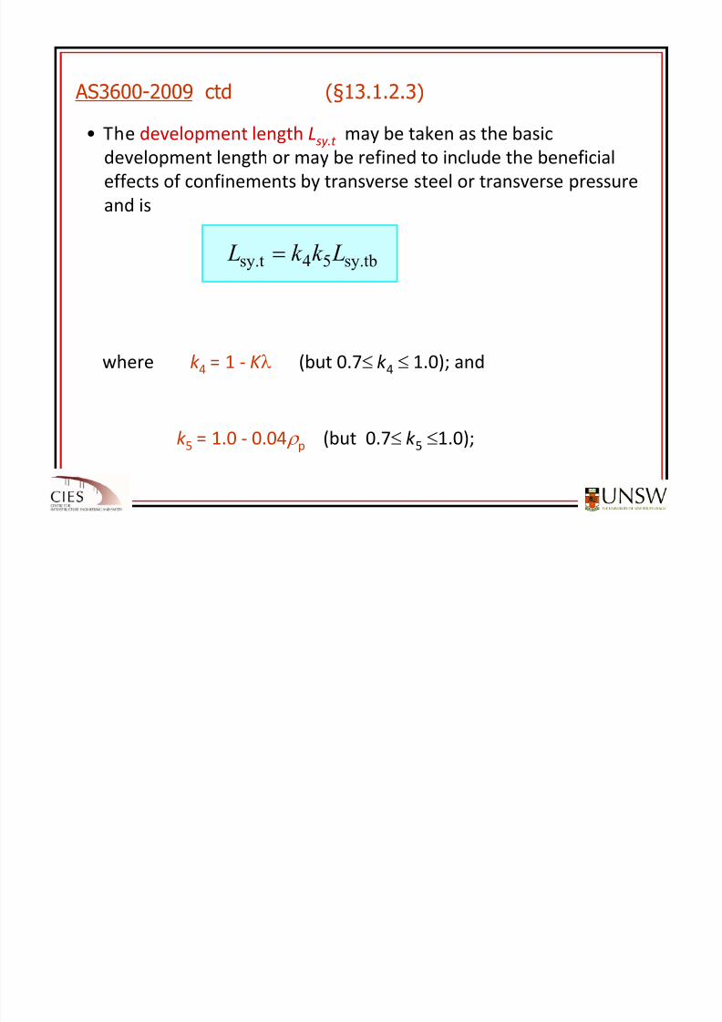
• The development length Lsy.t may be taken as the basic
development length or may be refined to include the beneficial
effects of confinements by transverse steel or transverse pressure
and is
where k 4 = 1 ‐ K λ (but 0.7≤ k 4 ≤ 1.0); and
k 5 = 1.0 ‐ 0.04 ρ p (but 0.7≤ k 5 ≤1.0);
AS3600-2009 ctd (§13.1.2.3)
sy.tb54sy.t Lk k L =
8/20/2019 Detailing of Reinforcement in Concrete Structures 28 Aug 2012
http://slidepdf.com/reader/full/detailing-of-reinforcement-in-concrete-structures-28-aug-2012 20/82
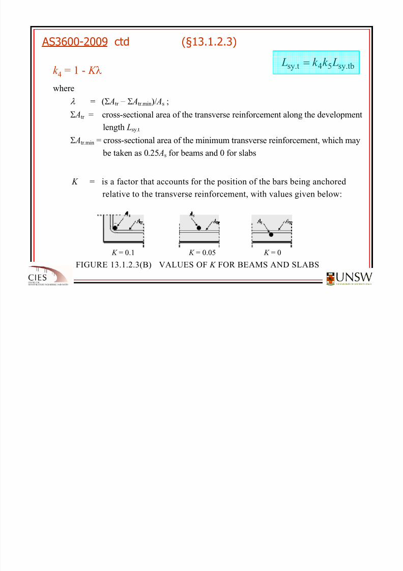
FIGURE 13.1.2.3(B) VALUES OF K FOR BEAMS AND SLABS
K = 0.1 K = 0.05 K = 0
sy.tb54sy.t Lk k L =k 4 = 1 - K λ
where
λ = (Σ Atr − Σ Atr.min)/ As ;
Σ Atr = cross-sectional area of the transverse reinforcement along the development
length Lsy.t
Σ Atr.min = cross-sectional area of the minimum transverse reinforcement, which may
be taken as 0.25 As for beams and 0 for slabs
As = cross-sectional area of a single bar of diameter d b being anchored
K = is a factor that accounts for the position of the bars being anchored
relative to the transverse reinforcement, with values given below:
AS3600-2009 ctd (§13.1.2.3)
8/20/2019 Detailing of Reinforcement in Concrete Structures 28 Aug 2012
http://slidepdf.com/reader/full/detailing-of-reinforcement-in-concrete-structures-28-aug-2012 21/82
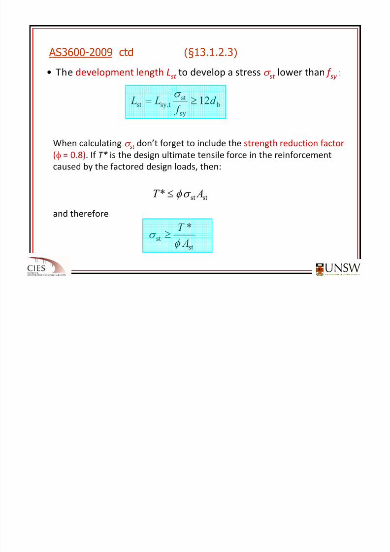
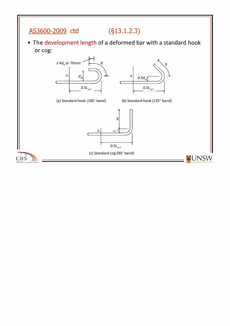
• The development length Lst to develop a stress σ st lower than f sy :
When calculating σ st don’t forget to include the strength reduction factor
(φ = 0.8). If T* is the design ultimate tensile force in the reinforcement
caused by the factored design loads, then:
and therefore
AS3600-2009 ctd (§13.1.2.3)
bsy
st
sy.tst
12d f
L L ≥= σ
st
st
stst
*
*
A
T
AT
φ σ
σ φ
≥
≤
8/20/2019 Detailing of Reinforcement in Concrete Structures 28 Aug 2012
http://slidepdf.com/reader/full/detailing-of-reinforcement-in-concrete-structures-28-aug-2012 22/82
8/20/2019 Detailing of Reinforcement in Concrete Structures 28 Aug 2012
http://slidepdf.com/reader/full/detailing-of-reinforcement-in-concrete-structures-28-aug-2012 23/82
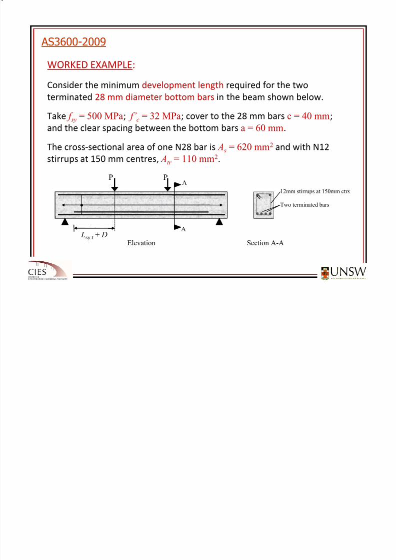
WORKED EXAMPLE:
Consider the minimum development length required for the two
terminated 28 mm diameter bottom bars in the beam shown below.
Take f sy = 500 MPa; f’ c = 32 MPa; cover to the 28 mm bars c = 40 mm;
and the clear spacing between the bottom bars a = 60 mm.
The cross‐sectional area of one N28 bar is A s = 620 mm2 and with N12
stirrups
at
150
mm
centres,
Atr = 110 mm2
.
AS3600-2009
P P
Lsy.t
12mm stirrups at 150mm ctrs
Two terminated bars
A
A
Elevation Section A-A
L sy.t + d
Lsy.t + D
8/20/2019 Detailing of Reinforcement in Concrete Structures 28 Aug 2012
http://slidepdf.com/reader/full/detailing-of-reinforcement-in-concrete-structures-28-aug-2012 24/82
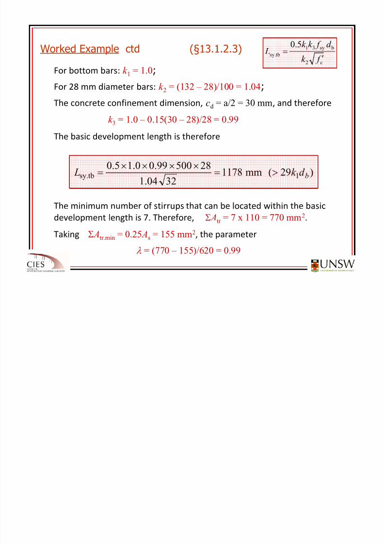
For bottom bars: k 1 = 1.0;
For 28 mm diameter bars: k 2 = (132 – 28)/100 = 1.04;
The
concrete
confinement
dimension, cd = a/2 = 30 mm,
and
thereforek 3 = 1.0 – 0.15(30 – 28)/28 = 0.99
The basic development length is therefore
The
minimum
number
of
stirrups
that
can
be
located
within
the
basic
development length is 7. Therefore, Σ Atr = 7 x 110 = 770 mm2.
Taking Σ Atr.min = 0.25 As = 155 mm2, the parameter
λ = (770 – 155)/620 = 0.99
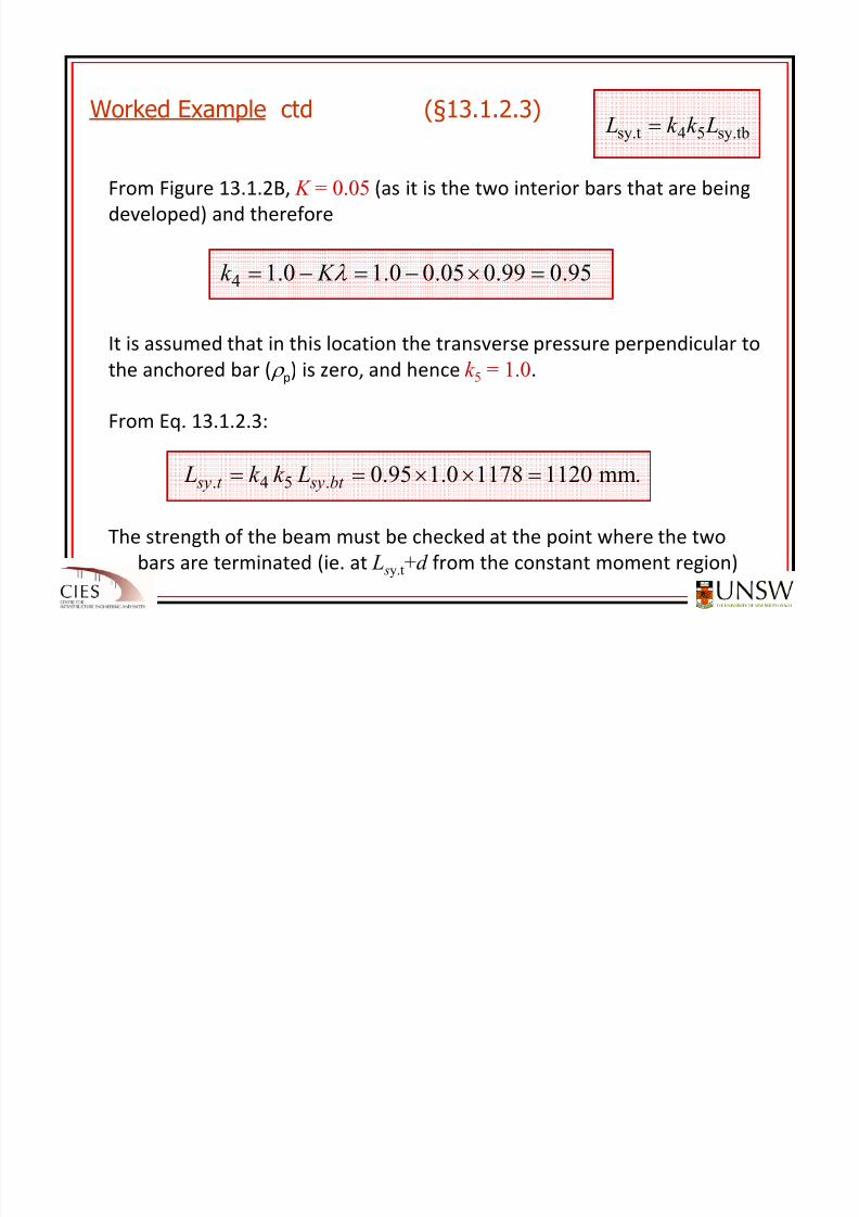
Worked Example ctd (§13.1.2.3)
)29(mm11783204.1
2850099.00.15.01sy.tb bd k L >=
××××=
c2
bsy31
sy.tb
5.0
f k
d f k k
L ′=
8/20/2019 Detailing of Reinforcement in Concrete Structures 28 Aug 2012
http://slidepdf.com/reader/full/detailing-of-reinforcement-in-concrete-structures-28-aug-2012 25/82
From Figure 13.1.2B, K = 0.05 (as it is the two interior bars that are being
developed) and therefore
It is assumed that in this location the transverse pressure perpendicular to
the anchored bar ( ρ p) is zero, and hence k 5 = 1.0.
From Eq. 13.1.2.3:
Worked Example ctd (§13.1.2.3)sy.tb54sy.t Lk k L =
95.099.005.00.10.14 =×−=−= λ K k
.mm112011780.195.0.54. =××== bt syt sy Lk k L
The strength of the beam must be checked at the point where the two
bars are terminated (ie. at L sy.t+d from the constant moment region)
8/20/2019 Detailing of Reinforcement in Concrete Structures 28 Aug 2012
http://slidepdf.com/reader/full/detailing-of-reinforcement-in-concrete-structures-28-aug-2012 26/82
Lapped Splices for bars in tension (13.2.2 Lapped Splices for bars in tension (13.2.2 – – AS3600AS3600‐‐2009):2009):
PLANAR VIEW
sL ad b s b
Lsy.t.lap
Note: For the purposes of determining cd , the dimension a shall be taken equal to ( sL-d b)
irrespective of the value of s b.
cd , = min (a/2, ccrit )
(i) 100% of bars spliced (no staggered splice)
cd , = min (a/2, ccrit )
(ii) 50% staggered splices
PLANAR VIEW
Lsy.t.lap
≥ 0.3 Lsy.t.lap
a
L
b
Note: For the purposes of determining cd , the dimension a shall be taken equal to 2 sL
irrespective of the value of s b.
(a/ 2, c )
(a/ 2, c )
cd = min (a/2, c)
(i) 100% of bars spliced (no staggered splices)
(ii) 50% staggered splicescd = min (a/2, c)
8/20/2019 Detailing of Reinforcement in Concrete Structures 28 Aug 2012
http://slidepdf.com/reader/full/detailing-of-reinforcement-in-concrete-structures-28-aug-2012 27/82
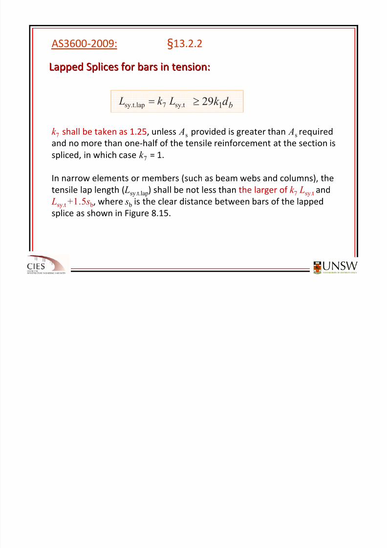
Lapped Splices for bars in tension:Lapped Splices for bars in tension:
AS3600‐2009: §13.2.2
sy.t7sy.t.lap Lk L =
bd k
129≥
k 7 shall be taken as 1.25, unless As provided is greater than As required
and no more than one‐half of the tensile reinforcement at the section is
spliced, in which case k 7
= 1.
In narrow elements or members (such as beam webs and columns), the
tensile lap length ( Lsy.t.lap) shall be not less than the larger of k 7 Lsy.t and
Lsy.t +1.5 s b, where s b is the clear distance between bars of the lapped
splice as
shown
in
Figure
8.15.
8/20/2019 Detailing of Reinforcement in Concrete Structures 28 Aug 2012
http://slidepdf.com/reader/full/detailing-of-reinforcement-in-concrete-structures-28-aug-2012 28/82
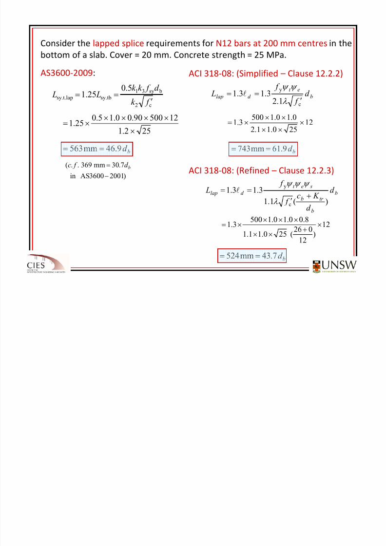
Consider the lapped splice requirements for N12 bars at 200 mm centres in the
bottom of
a slab.
Cover
= 20
mm.
Concrete
strength
= 25
MPa.
AS3600‐2009:
ACI 318‐08: (Refined – Clause 12.2.3)
b
et
d lap d f
f L
c
y
1.23.13.1
′==
λ
ψ ψ l
12250.11.2
0.10.15003.1 ×
××
×××=
bd 9.61mm743 ==
b
b
tr b
set
d lap d
d
K c f
f L
)(1.1
3.13.1
c
y
+′
==λ
ψ ψ ψ l
12
)12
026(250.11.1
8.00.10.15003.1 ×
+××
××××=
bd 7.43mm524 ==
ACI 318‐08: (Simplified – Clause 12.2.2)
c2
bsy31
sy.tbsy.t.lap
5.025.1
f k
d f k k L L
′==
252.1
1250090.00.15.025.1
×
×××××=
bd 9.46mm563 ==
)20013600ASin
7.30mm369..(
−
= bd f c
8/20/2019 Detailing of Reinforcement in Concrete Structures 28 Aug 2012
http://slidepdf.com/reader/full/detailing-of-reinforcement-in-concrete-structures-28-aug-2012 29/82
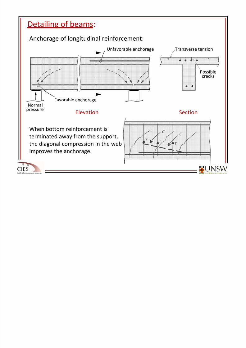
Detailing of beams:
Anchorage of
longitudinal
reinforcement:
Favorable
anchorage
Elevation Section
Unfavorable anchorage Transverse tension
Possible
cracks
Normal pressure
C
C
T T T
When bottom reinforcement is
terminated away
from
the
support,
the diagonal compression in the web
improves the anchorage.
8/20/2019 Detailing of Reinforcement in Concrete Structures 28 Aug 2012
http://slidepdf.com/reader/full/detailing-of-reinforcement-in-concrete-structures-28-aug-2012 30/82
Current wording:
“The design for flexural strength and detailing of flexural reinforcement
and pretensioned tendons at termination shall be extended from the
theoretical cut‐off point, or debonding point, by a length of 1.0D + Lsy.t, or
1.0D + Lpt, where
D
is
the
member
depth
at
the
theoretical
cut
‐off
point
or
theoretical debonding point”
‐ Problem 1: The wording does not make sense
‐ Problem 2: The rule is incorrect – a bar does not have to develop
its yield
stress
at
the
theoretical
cut
‐off
point
Amended wording:“Where flexural reinforcement and pretensioned tendons are to be
terminated, the
bars
or
tendons
shall
be
extended
from
the
theoretical
cut
‐
off point, or theoretical debonding point, by a length of at least 1.0D + Lst,
or 1.0D + Lpt, respectively, where D is the member depth at the theoretical
cut‐off point or theoretical debonding point”
AS3600-2009 Clause 8.1.10.1
8/20/2019 Detailing of Reinforcement in Concrete Structures 28 Aug 2012
http://slidepdf.com/reader/full/detailing-of-reinforcement-in-concrete-structures-28-aug-2012 31/82
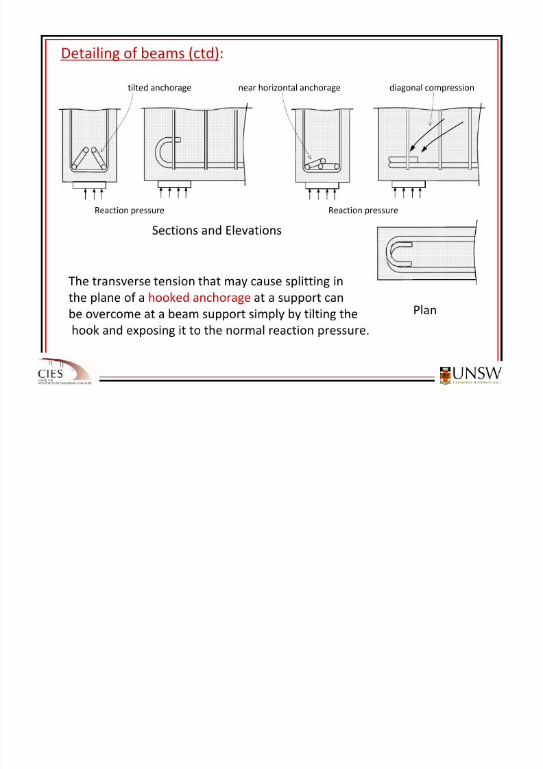
Detailing of beams (ctd):
tilted anchorage near horizontal anchorage diagonal compression
Reaction pressure Reaction pressure
Sections and
Elevations
Plan
The transverse tension that may cause splitting in
the plane
of
a hooked
anchorage at
a support
can
be overcome at a beam support simply by tilting the
hook and exposing it to the normal reaction pressure.
8/20/2019 Detailing of Reinforcement in Concrete Structures 28 Aug 2012
http://slidepdf.com/reader/full/detailing-of-reinforcement-in-concrete-structures-28-aug-2012 32/82
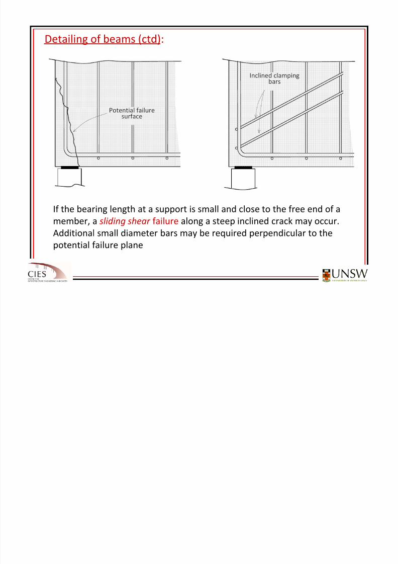
Detailing of beams (ctd):
If the bearing length at a support is small and close to the free end of a
member, a sliding shear failure along
a steep
inclined
crack
may
occur.
Additional small diameter bars may be required perpendicular to the
potential failure plane
Potential failuresurface
Inclined clamping
bars
8/20/2019 Detailing of Reinforcement in Concrete Structures 28 Aug 2012
http://slidepdf.com/reader/full/detailing-of-reinforcement-in-concrete-structures-28-aug-2012 33/82
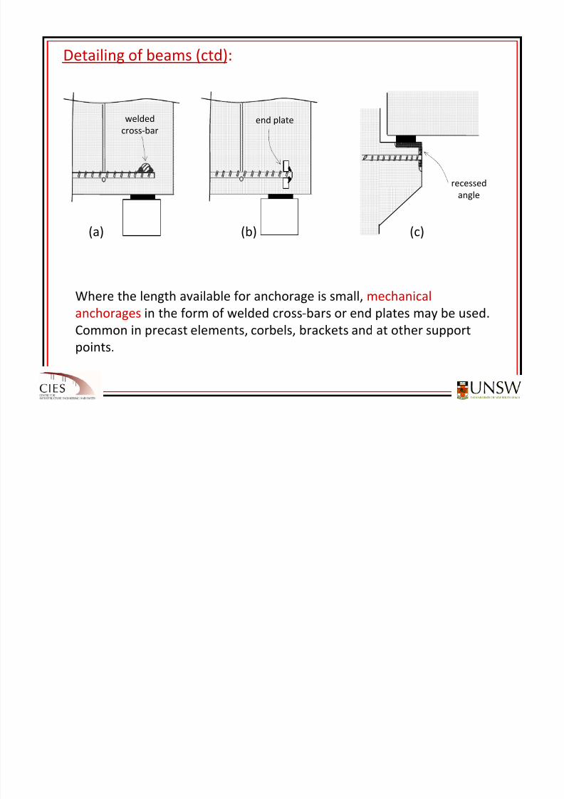
Detailing of beams (ctd):
Where the length available for anchorage is small, mechanical
anchorages in the
form
of
welded
cross
‐bars
or
end
plates
may
be
used.
Common in precast elements, corbels, brackets and at other support
points.
welded
cross‐barend plate
(a)
(b)
(c)
recessed
angle
8/20/2019 Detailing of Reinforcement in Concrete Structures 28 Aug 2012
http://slidepdf.com/reader/full/detailing-of-reinforcement-in-concrete-structures-28-aug-2012 34/82
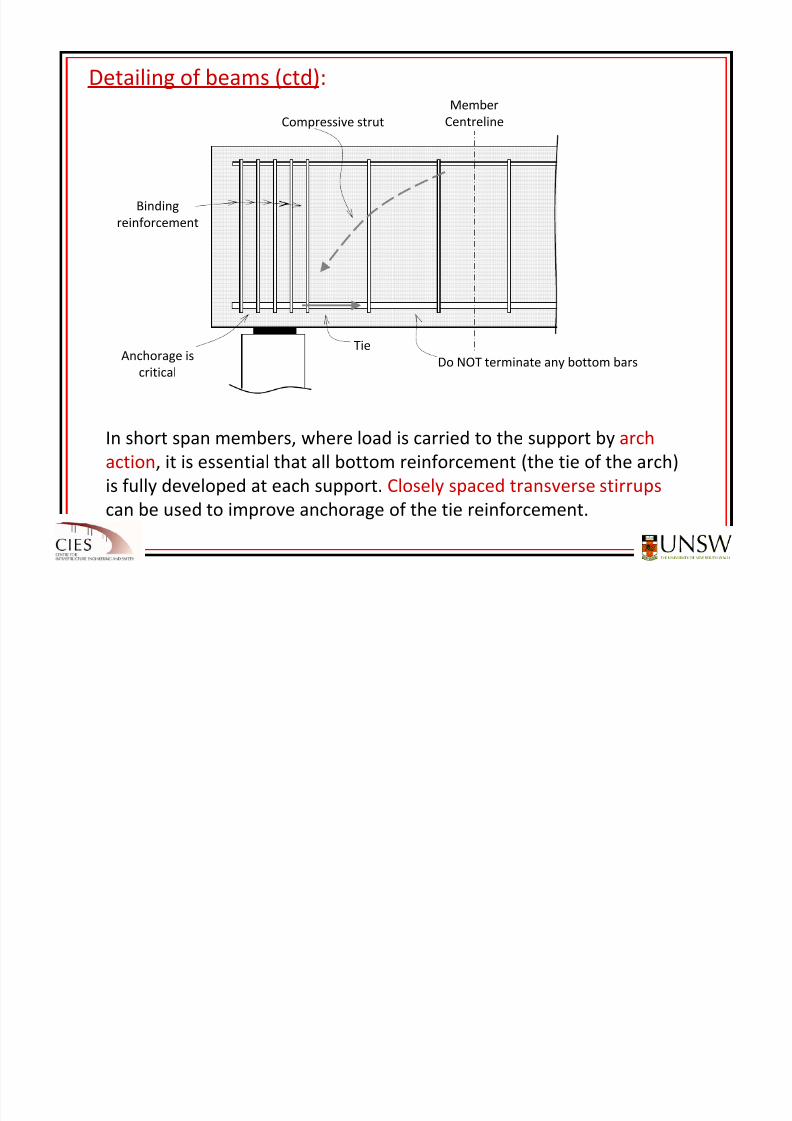
Detailing of beams (ctd):
In short
span
members,
where
load
is
carried
to
the
support
by
arch
action, it is essential that all bottom reinforcement (the tie of the arch)
is fully developed at each support. Closely spaced transverse stirrups
can be used to improve anchorage of the tie reinforcement.
Compressive strut
Tie
Do NOT terminate any bottom bars
Binding
reinforcement
Anchorage is
critical
Member
Centreline
8/20/2019 Detailing of Reinforcement in Concrete Structures 28 Aug 2012
http://slidepdf.com/reader/full/detailing-of-reinforcement-in-concrete-structures-28-aug-2012 35/82
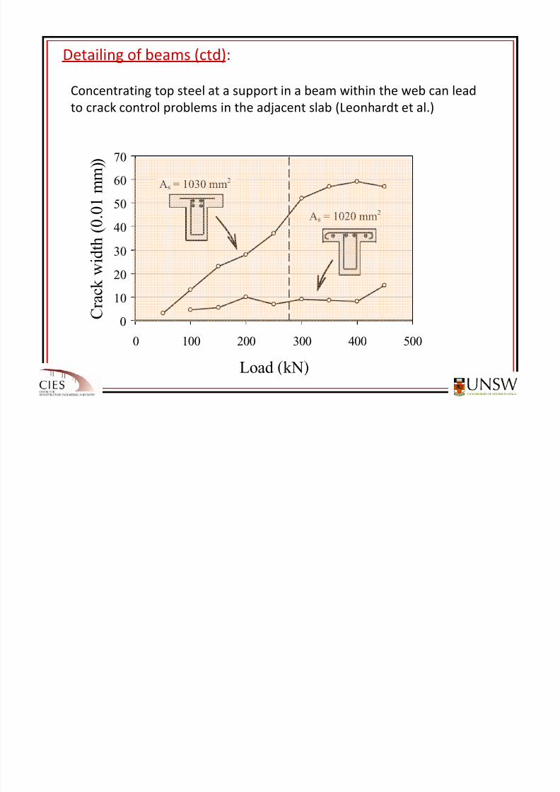
Detailing of beams (ctd):
Concentrating top steel at a support in a beam within the web can lead
to crack control problems in the adjacent slab (Leonhardt et al.)
0
10
20
3040
50
60
70
0 100 200 300 400 500
Load kN
C r
a c k w i d t h (
0 . 0
1 m m ) )
As = 1030 mm2
As = 1020 mm2
8/20/2019 Detailing of Reinforcement in Concrete Structures 28 Aug 2012
http://slidepdf.com/reader/full/detailing-of-reinforcement-in-concrete-structures-28-aug-2012 36/82
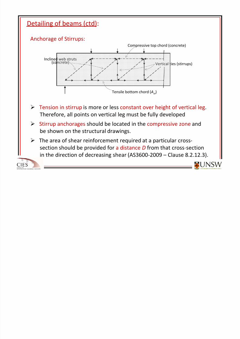
Detailing of beams (ctd):
Anchorage of Stirrups:
Tension in stirrup is more or less constant over height of vertical leg.
Therefore, all points on vertical leg must be fully developed
Stirrup anchorages should be located in the compressive zone and
be shown
on
the
structural
drawings.
The area of shear reinforcement required at a particular cross‐
section should be provided for a distance D from that cross‐section
in the direction of decreasing shear (AS3600‐2009 – Clause 8.2.12.3).
Compressive top chord (concrete)
Vertical ties (stirrups)Inclined web struts
(concrete)
Tensile bottom chord ( Ast )
8/20/2019 Detailing of Reinforcement in Concrete Structures 28 Aug 2012
http://slidepdf.com/reader/full/detailing-of-reinforcement-in-concrete-structures-28-aug-2012 37/82
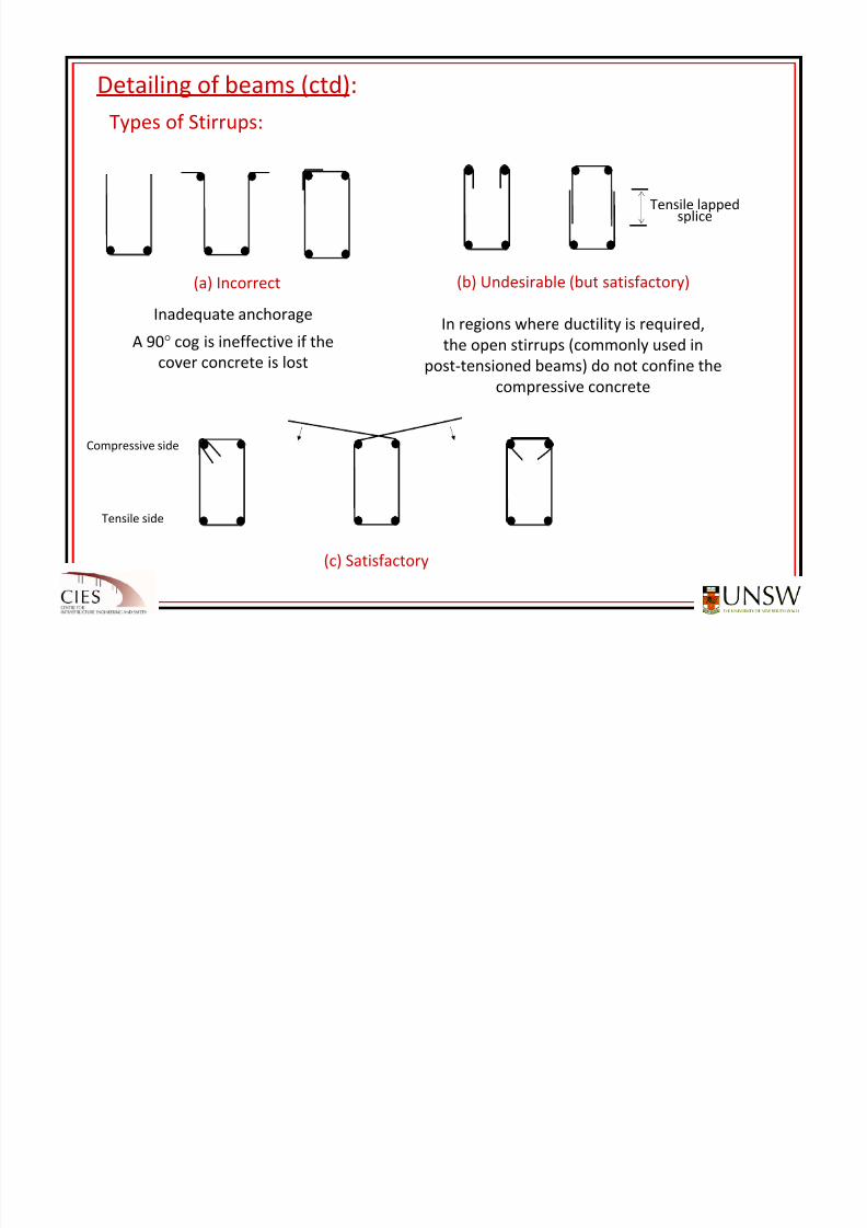
Detailing of beams (ctd):
Types of
Stirrups:
(a) Incorrect
Inadequate anchorage
A 90° cog is ineffective if the
cover concrete
is
lost
Tensile lapped
splice
(c) Satisfactory
Compressive side
Tensile side
(b) Undesirable (but satisfactory)
In regions where ductility is required,
the open stirrups (commonly used in
post‐tensioned
beams)
do
not
confine
the
compressive concrete
8/20/2019 Detailing of Reinforcement in Concrete Structures 28 Aug 2012
http://slidepdf.com/reader/full/detailing-of-reinforcement-in-concrete-structures-28-aug-2012 38/82
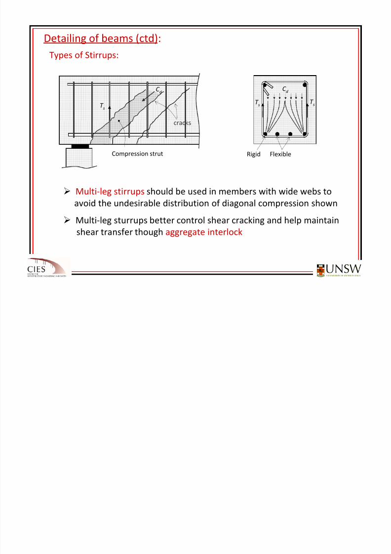
Detailing of beams (ctd):
Types of
Stirrups:
cracks
T s
C d
Compression strut
C d
T sT
s
Rigid Flexible
Multi‐leg stirrups should be used in members with wide webs to
avoid the undesirable distribution of diagonal compression shown
Multi‐leg
sturrups better
control
shear
cracking
and
help
maintain
shear transfer though aggregate interlock
8/20/2019 Detailing of Reinforcement in Concrete Structures 28 Aug 2012
http://slidepdf.com/reader/full/detailing-of-reinforcement-in-concrete-structures-28-aug-2012 39/82
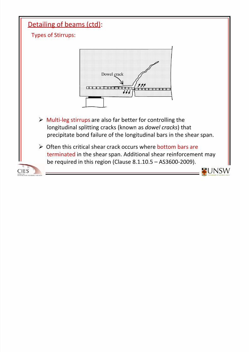
Detailing of beams (ctd):
Types of
Stirrups:
Multi‐leg stirrups are also far better for controlling the
longitudinal splitting cracks (known as dowel cracks) that
precipitate
bond
failure
of
the
longitudinal
bars
in
the
shear
span.
Often this critical shear crack occurs where bottom bars are
terminated in the shear span. Additional shear reinforcement may
be required in this region (Clause 8.1.10.5 – AS3600‐2009).
Dowel crack
8/20/2019 Detailing of Reinforcement in Concrete Structures 28 Aug 2012
http://slidepdf.com/reader/full/detailing-of-reinforcement-in-concrete-structures-28-aug-2012 40/82
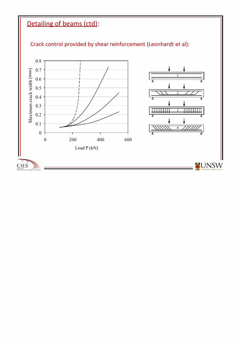
Detailing of beams (ctd):
Crack control provided by shear reinforcement (Leonhardt et al):
0
0.1
0.2
0.3
0.4
0.5
0.6
0.7
0.8
0 200 400 600
Load P (kN)
M a x i m u m c r a c k w i d t h ( m m
1
2
3
4
( m m )
8/20/2019 Detailing of Reinforcement in Concrete Structures 28 Aug 2012
http://slidepdf.com/reader/full/detailing-of-reinforcement-in-concrete-structures-28-aug-2012 41/82
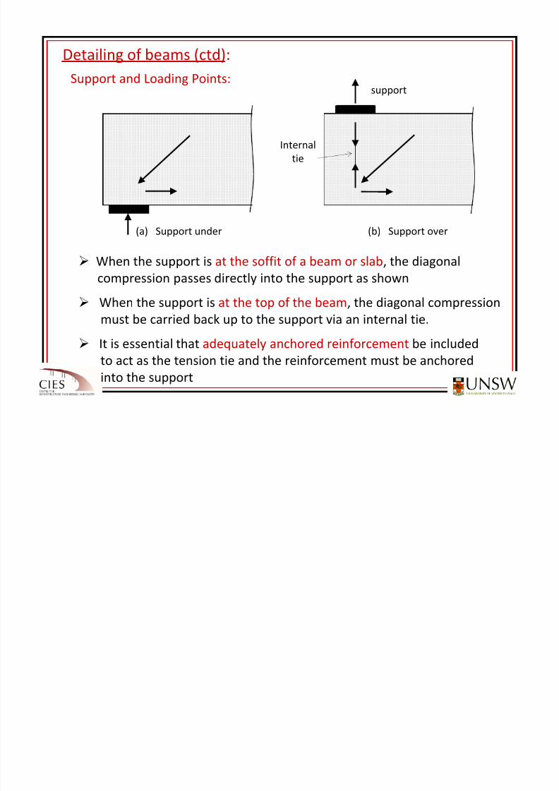
Detailing of beams (ctd):
Support and
Loading
Points:
When the support is at the soffit of a beam or slab, the diagonal
compression passes directly into the support as shown
When
the
support
is
at
the
top
of
the
beam,
the
diagonal
compression
must be carried back up to the support via an internal tie.
It is essential that adequately anchored reinforcement be included
to act as the tension tie and the reinforcement must be anchored
into
the
support
(a)
Support under
support
Internal
tie
(b)
Support over
8/20/2019 Detailing of Reinforcement in Concrete Structures 28 Aug 2012
http://slidepdf.com/reader/full/detailing-of-reinforcement-in-concrete-structures-28-aug-2012 42/82
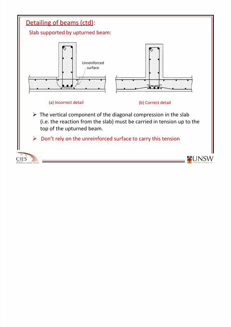
Detailing of beams (ctd):
Slab supported
by
upturned
beam:
(a) Incorrect detail
The vertical component of the diagonal compression in the slab
(i.e. the reaction from the slab) must be carried in tension up to the
top of
the
upturned
beam.
Don’t rely on the unreinforced surface to carry this tension
Unreinforced
surface
(b) Correct detail
8/20/2019 Detailing of Reinforcement in Concrete Structures 28 Aug 2012
http://slidepdf.com/reader/full/detailing-of-reinforcement-in-concrete-structures-28-aug-2012 43/82
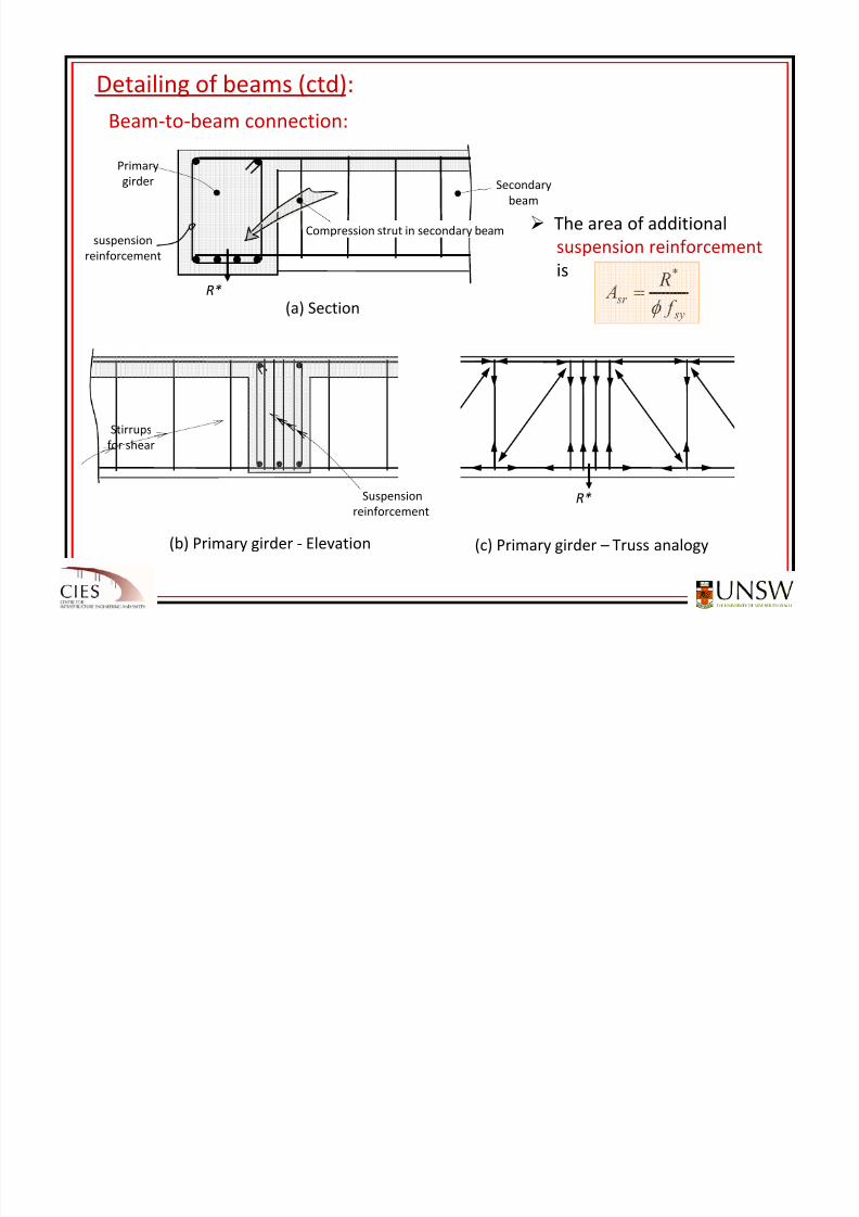
Detailing of beams (ctd):
Beam‐
to‐
beam
connection:
The area of additional
suspension reinforcement
is
Primary
girder
R*
suspensionreinforcement
(a) Section
Secondary
beam
Compression strut in secondary beam
Suspension
reinforcement
(b) Primary girder ‐ Elevation
Stirrups
for shear
(c) Primary girder – Truss analogy
R*
sy
sr f
R A
φ
*
=
8/20/2019 Detailing of Reinforcement in Concrete Structures 28 Aug 2012
http://slidepdf.com/reader/full/detailing-of-reinforcement-in-concrete-structures-28-aug-2012 44/82
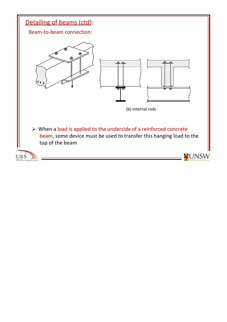
Detailing of beams (ctd):
Beam‐
to‐
beam
connection:
When a load is applied to the underside of a reinforced concrete
beam, some device must be used to transfer this hanging load to the
top of the beam
(b) Internal rods
8/20/2019 Detailing of Reinforcement in Concrete Structures 28 Aug 2012
http://slidepdf.com/reader/full/detailing-of-reinforcement-in-concrete-structures-28-aug-2012 45/82
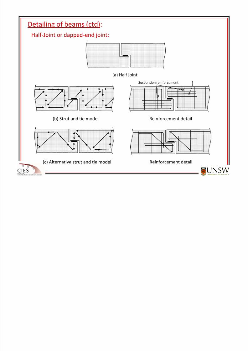
Detailing of beams (ctd):
Half ‐
Joint
or
dapped‐
end
joint:
(a) Half joint
(b) Strut and tie model Reinforcement detail
Hairpin reinforcement
Suspension reinforcement
(c) Alternative strut and tie model Reinforcement detail
8/20/2019 Detailing of Reinforcement in Concrete Structures 28 Aug 2012
http://slidepdf.com/reader/full/detailing-of-reinforcement-in-concrete-structures-28-aug-2012 46/82
•• Excessive crackingExcessive cracking due to due to restrained deformationrestrained deformation or or external external
loadsloads is a common cause of damage in reinforced concrete is a common cause of damage in reinforced concrete
structures.structures.
•• Excessive crackingExcessive cracking in the hardened concrete can be avoided in the hardened concrete can be avoided
by including sufficient reinforcement at sufficienby including sufficient reinforcement at sufficiently close tly close
spacingsspacings..
•• Shrinkage Shrinkage causes a causes a gradual widening of existing cracksgradual widening of existing cracks and and
timetime‐‐dependent crackingdependent cracking in previously uncracked regions.in previously uncracked regions.
Detailing
for
Crack
ControlDetailing
for
Crack
Control
•• TheThe minimum quantities of reinforcement minimum quantities
of
reinforcement
specified for crackspecified for
crack
control in AS3600 may not be what is actually requcontrol in AS3600 may not be what is actually required in all ired in all
circumstances.circumstances.
8/20/2019 Detailing of Reinforcement in Concrete Structures 28 Aug 2012
http://slidepdf.com/reader/full/detailing-of-reinforcement-in-concrete-structures-28-aug-2012 47/82
8/20/2019 Detailing of Reinforcement in Concrete Structures 28 Aug 2012
http://slidepdf.com/reader/full/detailing-of-reinforcement-in-concrete-structures-28-aug-2012 48/82
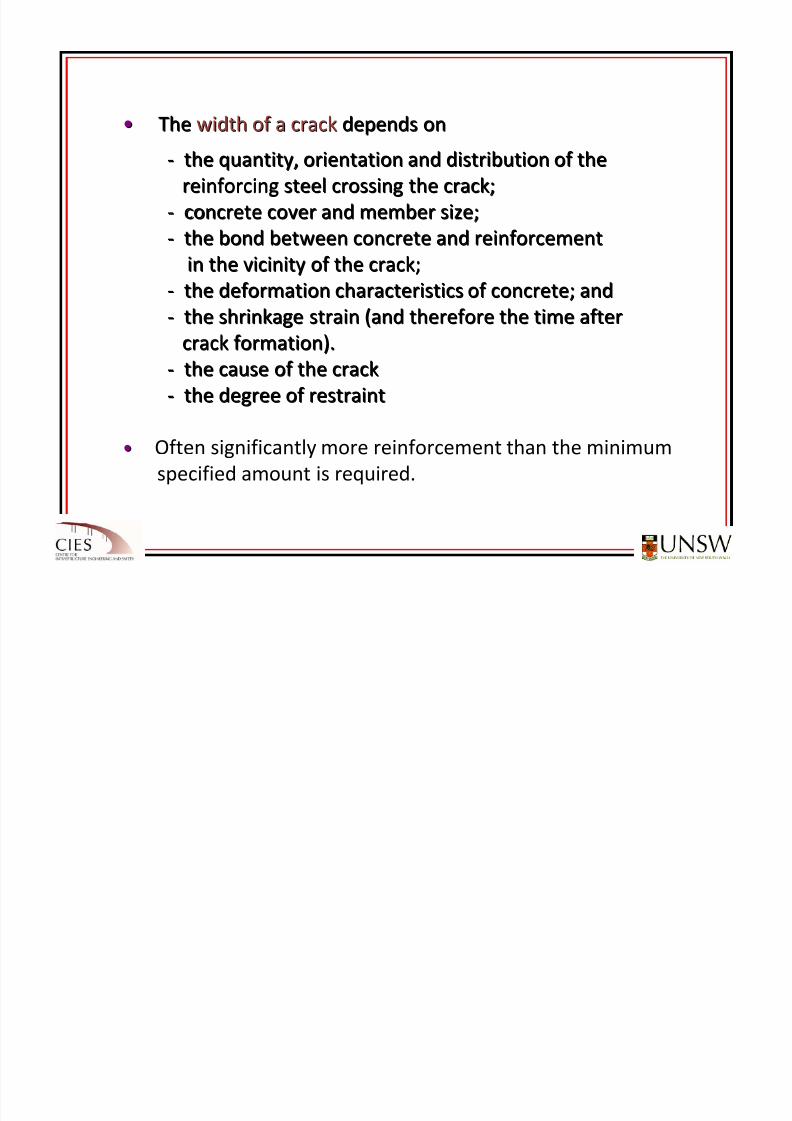
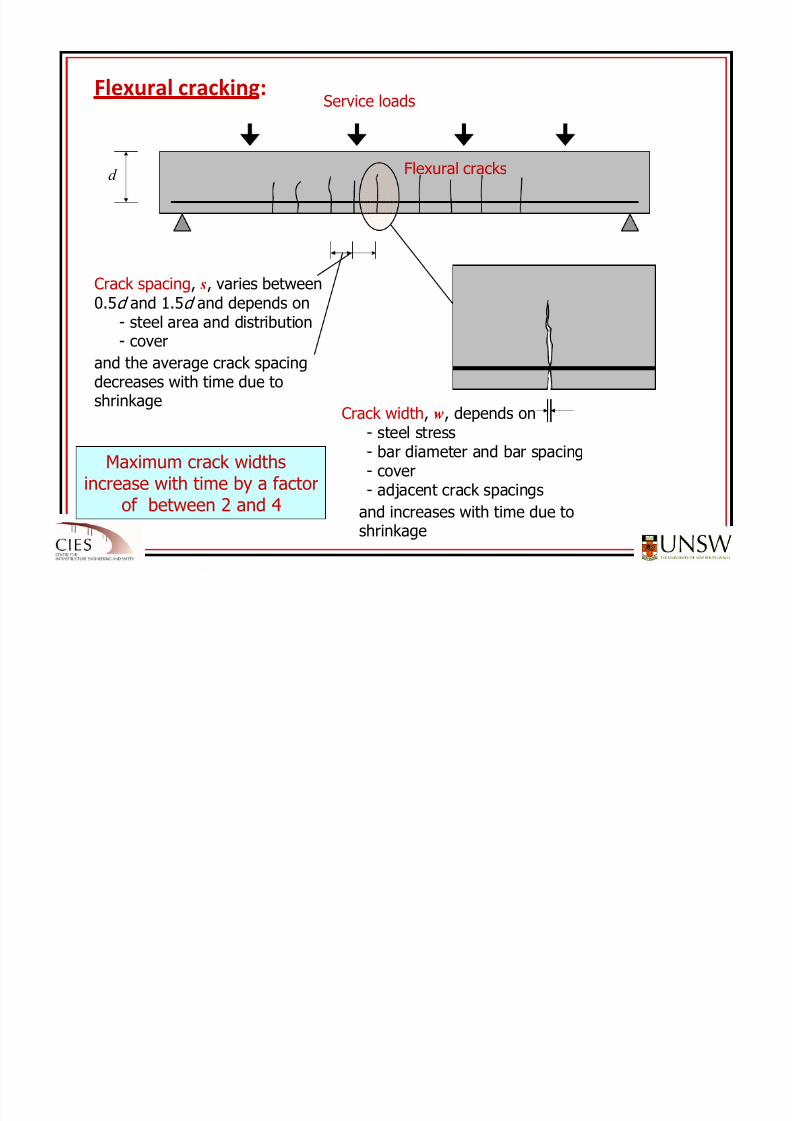
Crack spacing, s, varies between0.5d and 1.5d and depends on
- steel area and distribution- cover
Crack width, w, depends on
- steel stress- bar diameter and bar spacing- cover- adjacent crack spacings
and the average crack spacingdecreases with time due toshrinkage
and increases with time due toshrinkage
d
Maximum crack widthsincrease with time by a factor
of between 2 and 4
Service loads
Flexural cracks
Flexural cracking:
8/20/2019 Detailing of Reinforcement in Concrete Structures 28 Aug 2012
http://slidepdf.com/reader/full/detailing-of-reinforcement-in-concrete-structures-28-aug-2012 49/82
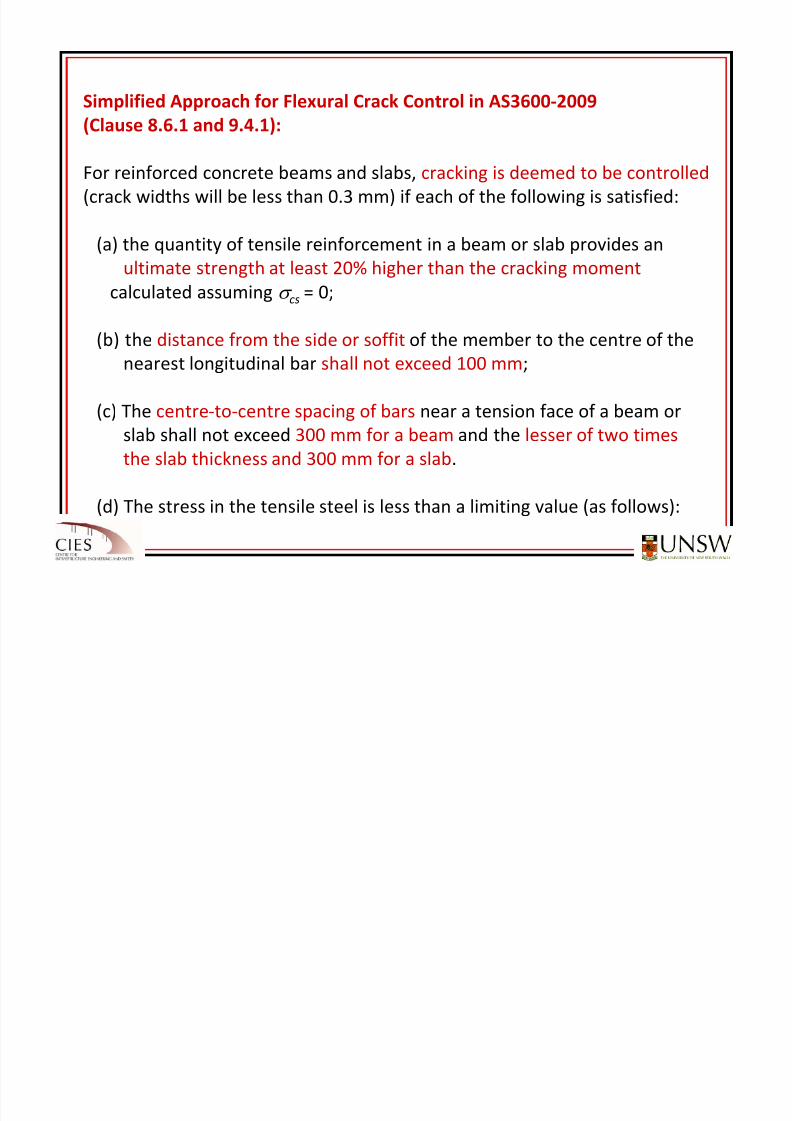
Simplified Approach for Flexural Crack Control in AS3600‐2009
(Clause 8.6.1
and
9.4.1):
For reinforced concrete beams and slabs, cracking is deemed to be controlled
(crack widths will be less than 0.3 mm) if each of the following is satisfied:
(a) the quantity of tensile reinforcement in a beam or slab provides an
ultimate strength at least 20% higher than the cracking moment
calculated assuming σ cs = 0;
(b) the distance
from
the
side
or
soffit of
the
member
to
the
centre
of
the
nearest longitudinal bar shall not exceed 100 mm;
(c) The centre‐to‐centre spacing of bars near a tension face of a beam or
slab shall
not
exceed
300
mm
for
a beam and
the
lesser
of
two
times
the slab thickness and 300 mm for a slab.
(d) The stress in the tensile steel is less than a limiting value (as follows):
8/20/2019 Detailing of Reinforcement in Concrete Structures 28 Aug 2012
http://slidepdf.com/reader/full/detailing-of-reinforcement-in-concrete-structures-28-aug-2012 50/82
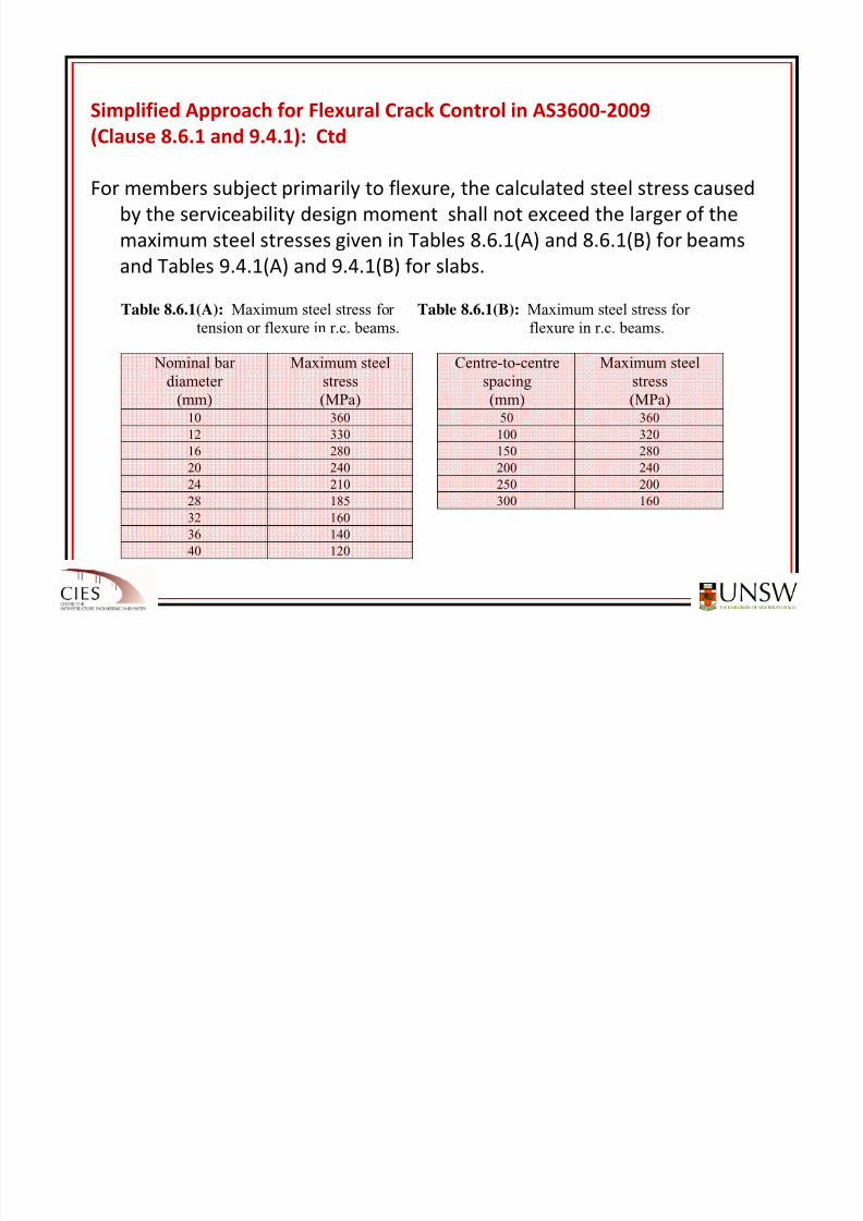
Simplified Approach for Flexural Crack Control in AS3600‐2009
(Clause 8.6.1
and
9.4.1):
Ctd
For members subject primarily to flexure, the calculated steel stress caused
by the serviceability design moment shall not exceed the larger of the
maximum steel
stresses
given
in
Tables
8.6.1(A)
and
8.6.1(B)
for beams
and Tables 9.4.1(A) and 9.4.1(B) for slabs.
Table 8.6.1(A): Maximum steel stress for Table 8.6.1(B): Maximum steel stress for
tension or flexure in r.c. beams. flexure in r.c. beams.
Nominal bardiameter
(mm)
Maximum steelstress
(MPa)
Centre-to-centrespacing
(mm)
Maximum steelstress
(MPa)10 360 50 360
12 330 100 320
16 280 150 280
20 240 200 240
24 210 250 200
28 185 300 160
32 160
36 140
40 120
8/20/2019 Detailing of Reinforcement in Concrete Structures 28 Aug 2012
http://slidepdf.com/reader/full/detailing-of-reinforcement-in-concrete-structures-28-aug-2012 51/82
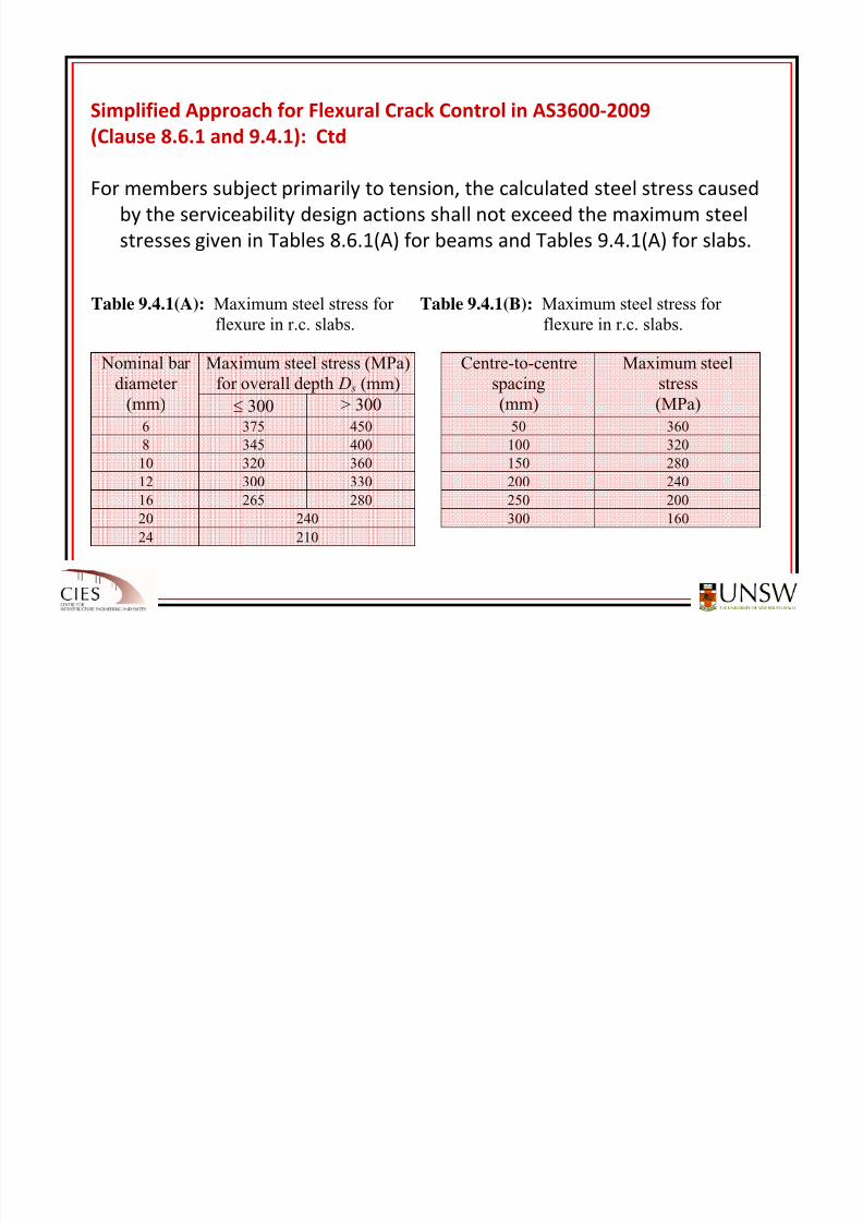
Simplified Approach for Flexural Crack Control in AS3600‐2009
(Clause 8.6.1
and
9.4.1):
Ctd
For members subject primarily to tension, the calculated steel stress caused
by the serviceability design actions shall not exceed the maximum steel
stresses given
in
Tables
8.6.1(A)
for
beams
and
Tables
9.4.1(A)
for
slabs.
Table 9.4.1(A): Maximum steel stress for Table 9.4.1(B): Maximum steel stress for
flexure in r.c. slabs. flexure in r.c. slabs.
Maximum steel stress (MPa)for overall depth D s (mm)
Nominal bardiameter
(mm) ≤ 300 > 300
Centre-to-centrespacing
(mm)
Maximum steelstress
(MPa)
6 375 450 50 360
8 345 400 100 320
10 320 360 150 280
12 300 330 200 24016 265 280 250 200
20 240 300 160
24 210
8/20/2019 Detailing of Reinforcement in Concrete Structures 28 Aug 2012
http://slidepdf.com/reader/full/detailing-of-reinforcement-in-concrete-structures-28-aug-2012 52/82
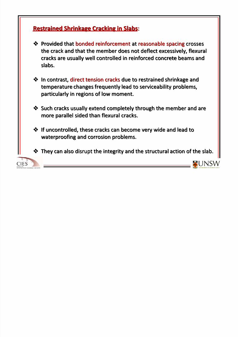
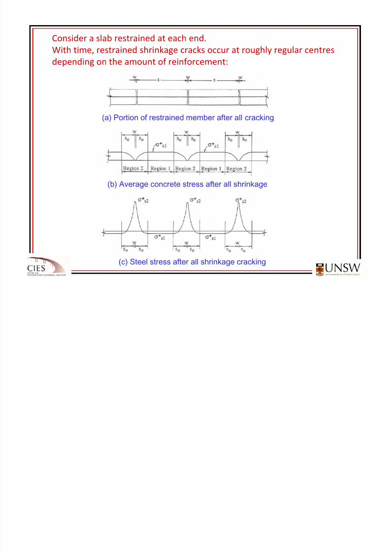
Restrained Shrinkage Cracking in SlabsRestrained Shrinkage Cracking in Slabs::
Provided that Provided that bonded reinforcement bonded reinforcement at at reasonable spacingreasonable spacing crossescrosses
the crack and that the member does notthe crack and that the member does not deflect excessively, flexuraldeflect excessively, flexural
cracks are usually well controlled in reinforced concrete cracks are usually well controlled in reinforced concrete beams and beams and
slabs. slabs.
In contrast, In contrast, direct tension cracksdirect tension cracks due to restrained shrinkage and due to restrained shrinkage and
temperature changes frequently lead to serviceability probtemperature changes frequently lead to serviceability problems, lems,
particularly in regions of low moment. particularly in regions of low moment.
Such cracks usually extend completely through the member and aSuch cracks usually extend completely through the member and are re
more parallel sided than flexural cracks. more parallel sided than flexural cracks.
If
uncontrolled,
these
cracks
can
become
very
wide
and
lead
toIf
uncontrolled,
these
cracks
can
become
very
wide
and
lead
towaterproofing and corrosion problems. waterproofing and corrosion problems.
They can also disrupt the integrity and the structural action They can also disrupt the integrity and the structural action of the slab.of the slab.
Th l b i t i d b b d h i k i d t i
8/20/2019 Detailing of Reinforcement in Concrete Structures 28 Aug 2012
http://slidepdf.com/reader/full/detailing-of-reinforcement-in-concrete-structures-28-aug-2012 53/82
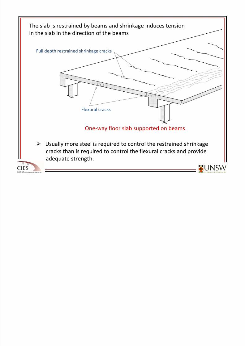
Flexural cracks
One‐way floor slab supported on beams
Full depth restrained shrinkage cracks
Usually more steel is required to control the restrained shrinkage
cracks than is required to control the flexural cracks and provide
adequate strength.
The slab is restrained by beams and shrinkage induces tension
in the slab in the direction of the beams
R t i d Sh i k C ki i Sl bR t i d Sh i k C ki i Sl b CtdCtd
8/20/2019 Detailing of Reinforcement in Concrete Structures 28 Aug 2012
http://slidepdf.com/reader/full/detailing-of-reinforcement-in-concrete-structures-28-aug-2012 54/82
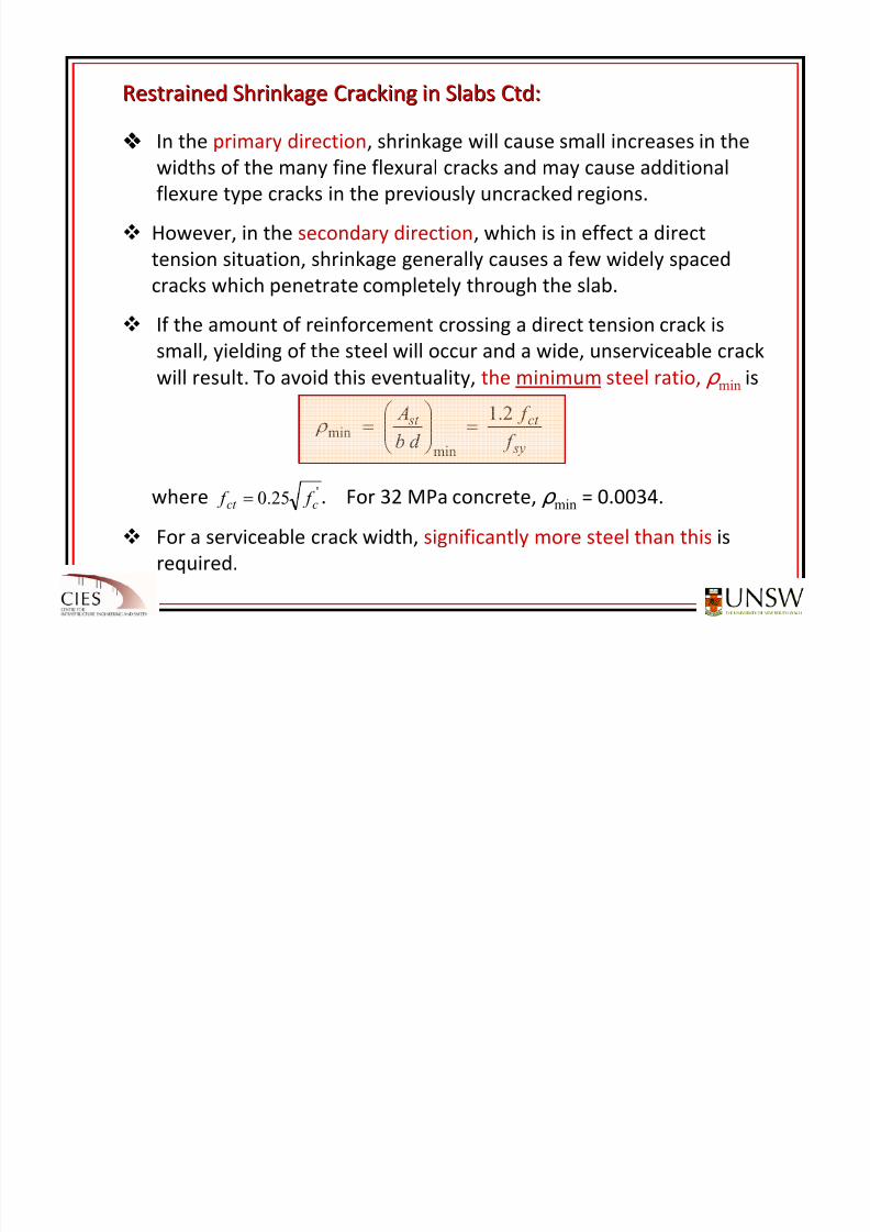
Restrained Shrinkage Cracking in Slabs Restrained Shrinkage Cracking in Slabs CtdCtd::
In the
primary
direction,
shrinkage
will
cause
small
increases
in
the
widths of the many fine flexural cracks and may cause additional
flexure type cracks in the previously uncracked regions.
However, in the secondary direction, which is in effect a direct
tension situation,
shrinkage
generally
causes
a few
widely spaced
cracks which penetrate completely through the slab.
If the amount of reinforcement crossing a direct tension crack is
small, yielding of the steel will occur and a wide, unserviceable crack
will result.
To
avoid
this
eventuality,
the
minimum steel
ratio,
ρ min is
where . For 32 MPa concrete, ρ min = 0.0034.
For a serviceable crack width, significantly more steel than this is
required.
sy
ct st
f
f
d b
A 2.1
min
min =⎟⎟ ⎠
⎞⎜⎜⎝
⎛ = ρ
'25.0 cct f f =
8/20/2019 Detailing of Reinforcement in Concrete Structures 28 Aug 2012
http://slidepdf.com/reader/full/detailing-of-reinforcement-in-concrete-structures-28-aug-2012 55/82
Crack Control in Slabs Crack Control in Slabs – –AS3600AS3600‐‐2009:2009:
Where the ends of a slab are restrained and the slab is not free to
expand or contract in the secondary direction, the minimum area of
reinforcement in the restrained direction is given by either Eq. 1a,
1b or 1c, as appropriate (see below).
For a slab fully enclosed within a building except for a brief period of
weather exposure during construction:
(i)
where
a
strong
degree
of
control over
cracking
is
required:
(ii) where a moderate degree of control over cracking is required:
(iii) where a minor degree of control over cracking is required:
( ) )a2.9(10)5.20.6( 3min
−×−= Db A cp s σ
( ) ) b2.9(10)5.25.3( 3min
−×−= Db A cp s σ
( ) )c2.9(10)5.275.1( 3min
−×−= Db A cp s σ
(1a)
(1b)
(1c)
F ll h l b f di i i E Cl ifi i A1
8/20/2019 Detailing of Reinforcement in Concrete Structures 28 Aug 2012
http://slidepdf.com/reader/full/detailing-of-reinforcement-in-concrete-structures-28-aug-2012 56/82
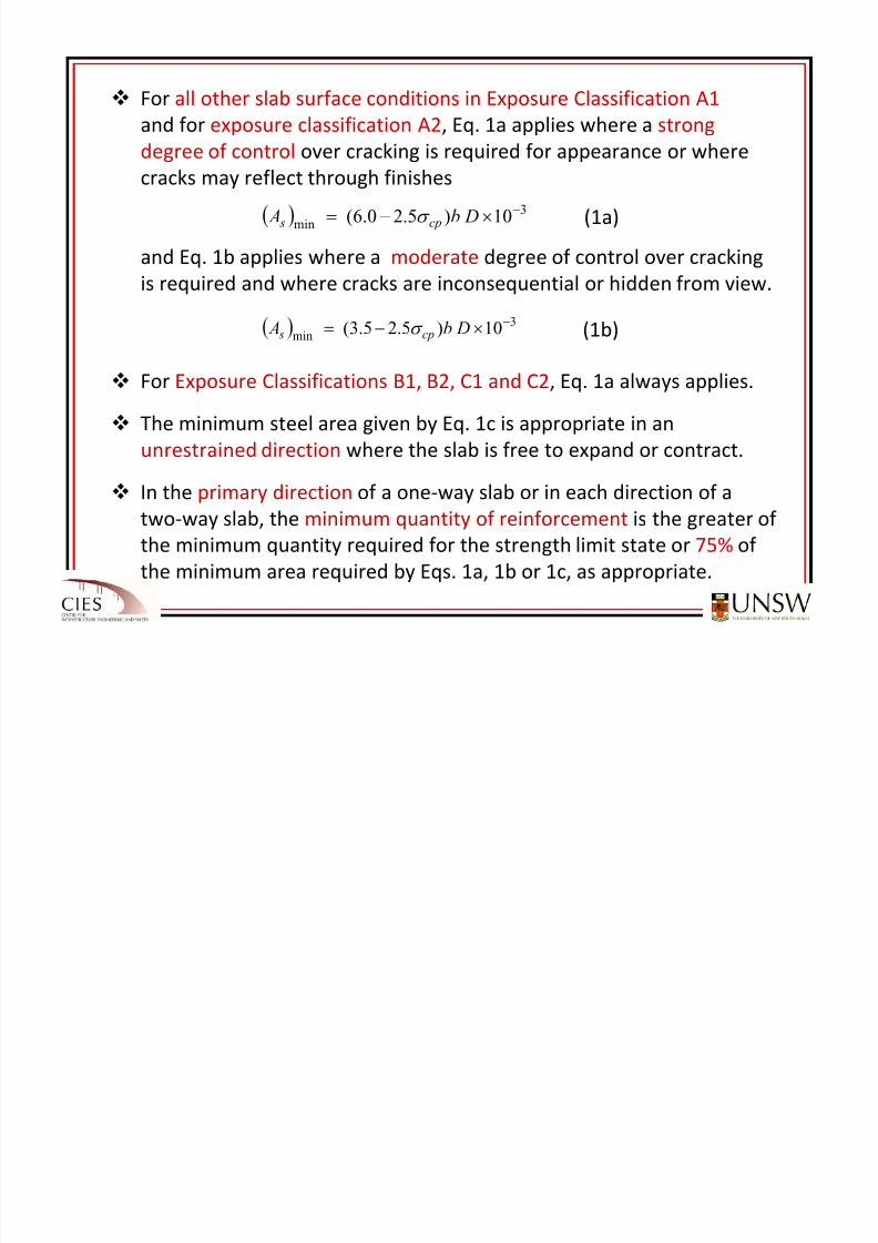
For all other slab surface conditions in Exposure Classification A1
and
for
exposure
classification
A2,
Eq.
1a
applies
where
a
strong
degree of control over cracking is required for appearance or where
cracks may reflect through finishes
and Eq.
1b
applies
where
a
moderate degree of
control
over
cracking
is required and where cracks are inconsequential or hidden from view.
For Exposure
Classifications
B1,
B2,
C1
and
C2,
Eq.
1a
always
applies.
The minimum steel area given by Eq. 1c is appropriate in an
unrestrained direction where the slab is free to expand or contract.
In the
primary
direction of
a one
‐way
slab
or
in
each
direction
of
a
two‐way slab, the minimum quantity of reinforcement is the greater of
the minimum quantity required for the strength limit state or 75% of
the minimum area required by Eqs. 1a, 1b or 1c, as appropriate.
( ) )a2.9(10)5.20.6( 3min
−×−= Db A cp s σ
( ) ) b2.9(10)5.25.3(3
min−×−= Db A cp s σ
(1a)
(1b)
8/20/2019 Detailing of Reinforcement in Concrete Structures 28 Aug 2012
http://slidepdf.com/reader/full/detailing-of-reinforcement-in-concrete-structures-28-aug-2012 57/82
8/20/2019 Detailing of Reinforcement in Concrete Structures 28 Aug 2012
http://slidepdf.com/reader/full/detailing-of-reinforcement-in-concrete-structures-28-aug-2012 58/82
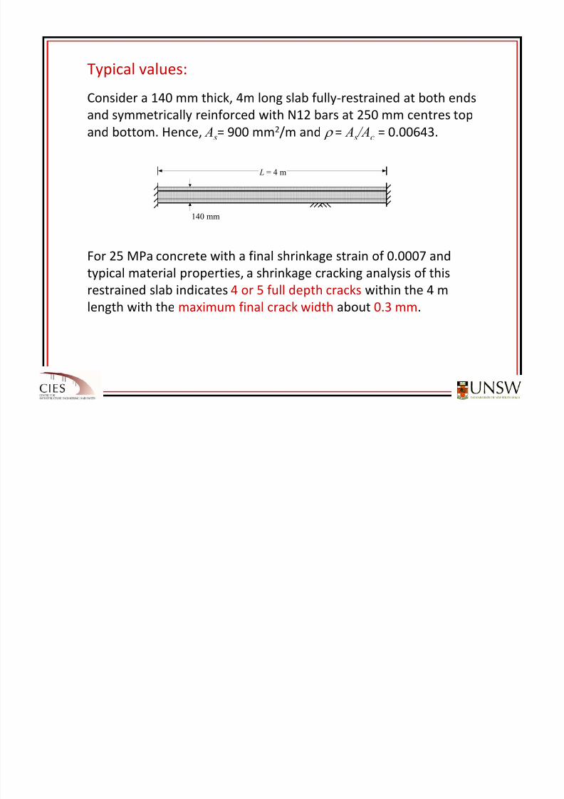
Typical values:
Consider a 140 mm thick, 4m long slab fully‐restrained at both ends
and symmetrically reinforced with N12 bars at 250 mm centres top
and bottom. Hence, A s= 900 mm2/m and ρ = A s /Ac = 0.00643.
L = 4 m
140 mm
For 25 MPa concrete with a final shrinkage strain of 0.0007 and
typical material properties, a shrinkage cracking analysis of this
restrained slab indicates 4 or 5 full depth cracks within the 4 m
length with the maximum final crack width about 0.3 mm.
8/20/2019 Detailing of Reinforcement in Concrete Structures 28 Aug 2012
http://slidepdf.com/reader/full/detailing-of-reinforcement-in-concrete-structures-28-aug-2012 59/82
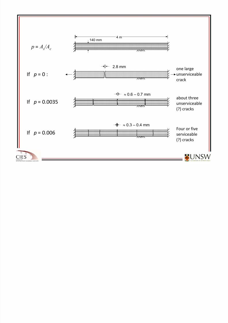
If p = 0 :
p = A s /Ac
2.8 mm one large
unserviceable
crack
If p = 0.0035
≈ 0.6 – 0.7 mmabout
three
unserviceable
(?) cracks
If p = 0.006
≈ 0.3 – 0.4 mmFour
or
five
serviceable
(?) cracks
4 m140 mm
Detailing of columns:
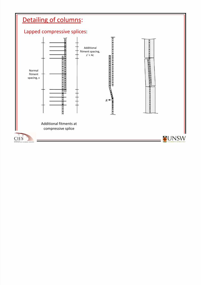
8/20/2019 Detailing of Reinforcement in Concrete Structures 28 Aug 2012
http://slidepdf.com/reader/full/detailing-of-reinforcement-in-concrete-structures-28-aug-2012 60/82
g
Lapped compressive
splices:
Normal
fitment
spacing, s
Additional
fitment spacing,
s’ < 4c
R
Additional fitments at
compressive splice
Tension at
cranked bars
Unsatisfactory tension
splice in thin wall
Detailing of columns:
8/20/2019 Detailing of Reinforcement in Concrete Structures 28 Aug 2012
http://slidepdf.com/reader/full/detailing-of-reinforcement-in-concrete-structures-28-aug-2012 61/82
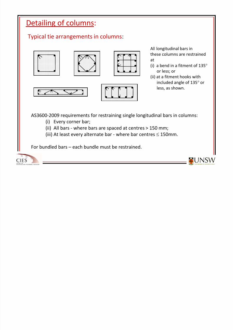
g
Typical tie
arrangements
in
columns:
AS3600‐2009 requirements for restraining single longitudinal bars in columns:
(i) Every corner bar;
(ii)
All
bars ‐
where
bars
are
spaced
at
centres >
150
mm;(iii) At least every alternate bar ‐ where bar centres ≤ 150mm.
For bundled bars – each bundle must be restrained.
All longitudinal bars in
these columns are restrained
at
(i)
a
bend
in
a
fitment
of
135°or less; or
(ii) at a fitment hooks with
included angle of 135° or
less, as shown.
Detailing of columns:
8/20/2019 Detailing of Reinforcement in Concrete Structures 28 Aug 2012
http://slidepdf.com/reader/full/detailing-of-reinforcement-in-concrete-structures-28-aug-2012 62/82
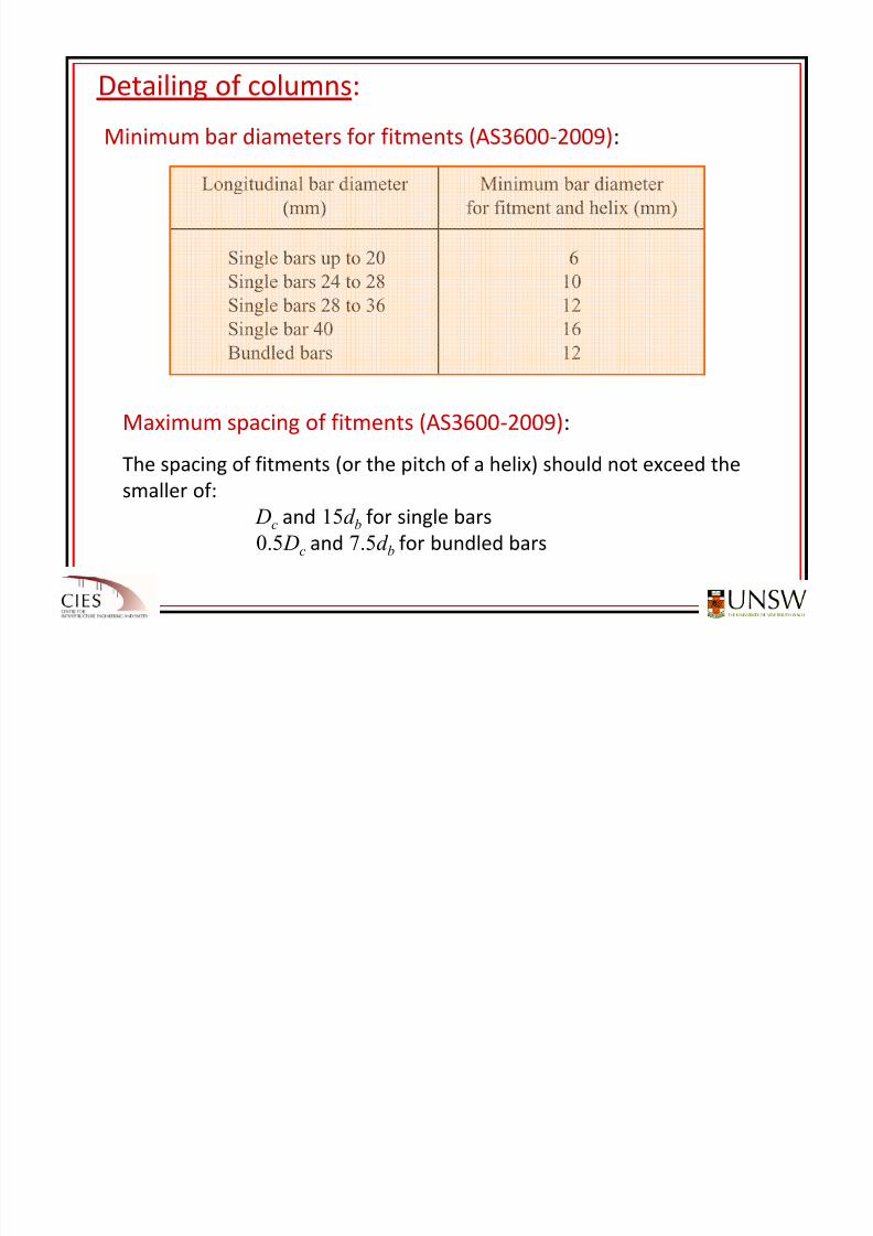
Minimum bar
diameters
for
fitments
(AS3600
‐2009):
610
12
16
12
Single bars up to 20Single bars 24 to 28
Single bars 28 to 36
Single bar 40
Bundled bars
Minimum bar diameter
for fitment and helix (mm)
Longitudinal bar diameter
(mm)
Maximum spacing of fitments (AS3600‐2009):
The spacing of fitments (or the pitch of a helix) should not exceed the
smaller of:
Dc and 15d b for single bars
0.5 Dc and 7.5d b for bundled bars
Detailing of Beam‐column Connections:
8/20/2019 Detailing of Reinforcement in Concrete Structures 28 Aug 2012
http://slidepdf.com/reader/full/detailing-of-reinforcement-in-concrete-structures-28-aug-2012 63/82
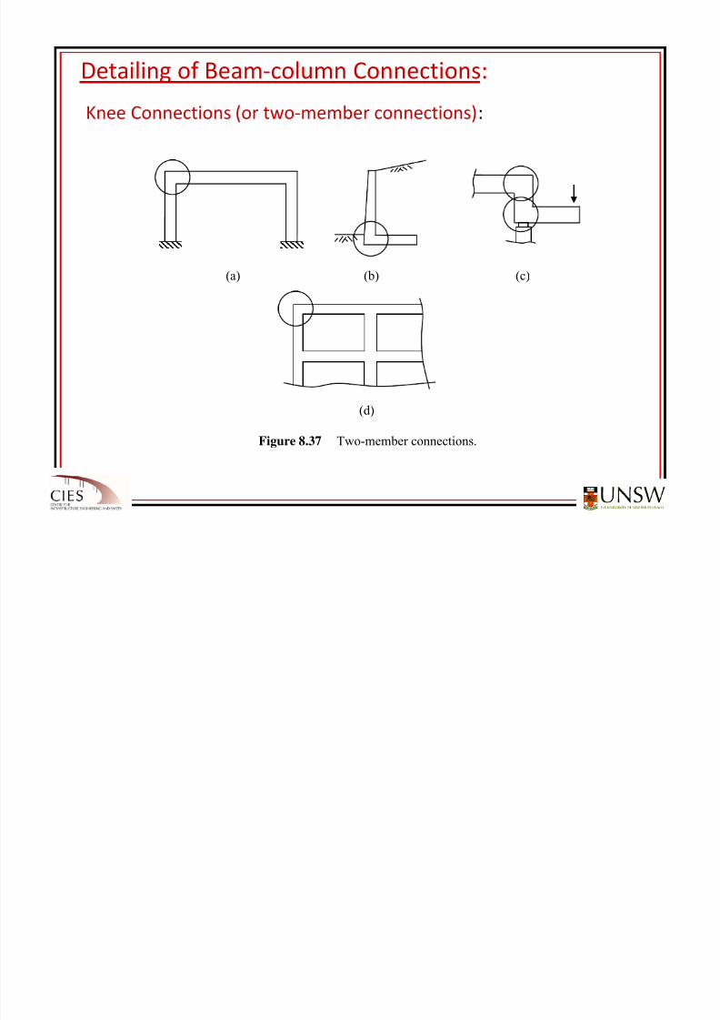
Knee Connections
(or
two
‐member
connections):
(a) (b) (c)
(d)
Figure 8.37 Two-member connections.
Detailing of Beam‐column Connections:
8/20/2019 Detailing of Reinforcement in Concrete Structures 28 Aug 2012
http://slidepdf.com/reader/full/detailing-of-reinforcement-in-concrete-structures-28-aug-2012 64/82
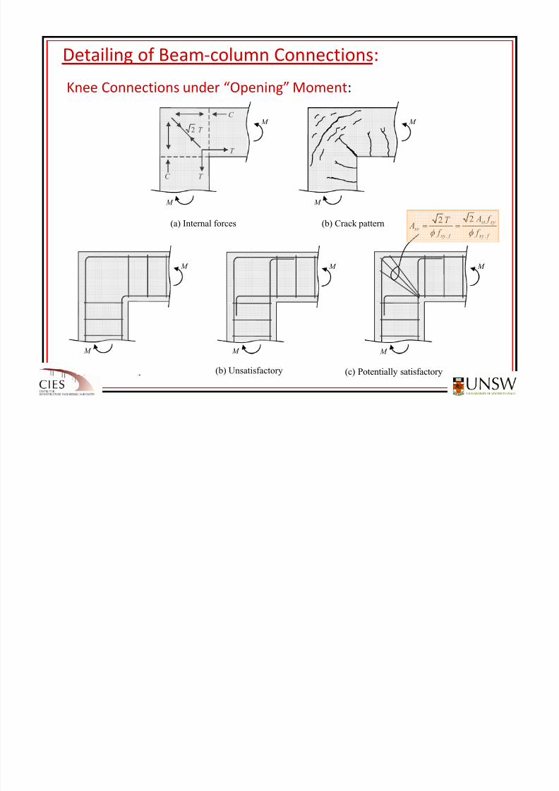
Knee Connections
under
“Opening” Moment:
M
M
C
C
T
T
T 2 M
M
(a) Internal forces (b) Crack pattern
M
M
M
M
(a) Unsatisfactory (b) Unsatisfactory
M
M
(c) Potentially satisfactory
f sy
sy st
f sy
sv f
f A
f
T A
..
22
φ φ ==
Detailing of Beam‐column Connections:
8/20/2019 Detailing of Reinforcement in Concrete Structures 28 Aug 2012
http://slidepdf.com/reader/full/detailing-of-reinforcement-in-concrete-structures-28-aug-2012 65/82
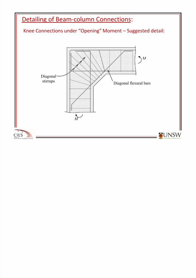
Knee Connections
under
“Opening” Moment
– Suggested
detail:
Diagonal flexural bars
Diagonal
stirrups
M
M
Detailing of Beam‐column Connections:
8/20/2019 Detailing of Reinforcement in Concrete Structures 28 Aug 2012
http://slidepdf.com/reader/full/detailing-of-reinforcement-in-concrete-structures-28-aug-2012 66/82
Knee Connections
under
“Closing” Moment:
M
M
T
T
C
C
T 2
M
M
(a) Internal forces (b) Crack pattern
M
M
(a) Wall or slab connection (when p ≤ f ct.f f sy) (b) Beam to column knee connection
M
M
8/20/2019 Detailing of Reinforcement in Concrete Structures 28 Aug 2012
http://slidepdf.com/reader/full/detailing-of-reinforcement-in-concrete-structures-28-aug-2012 67/82
Detailing of Beam‐column Connections:
8/20/2019 Detailing of Reinforcement in Concrete Structures 28 Aug 2012
http://slidepdf.com/reader/full/detailing-of-reinforcement-in-concrete-structures-28-aug-2012 68/82
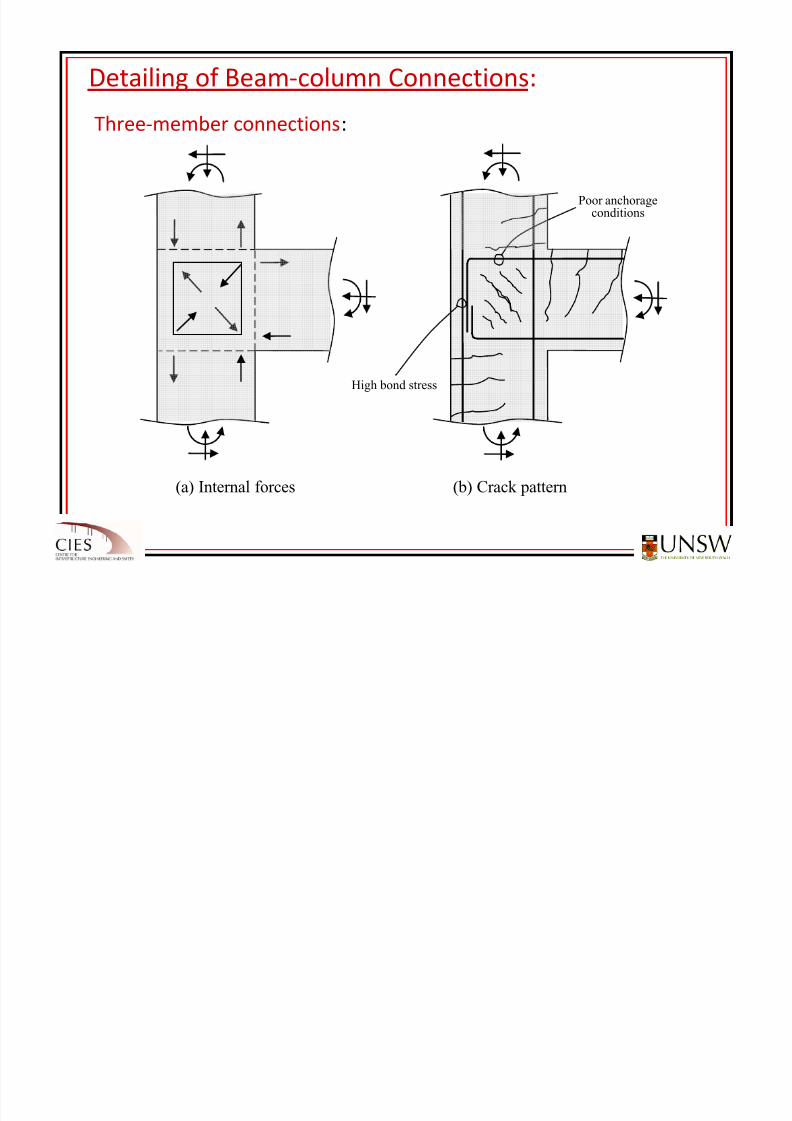
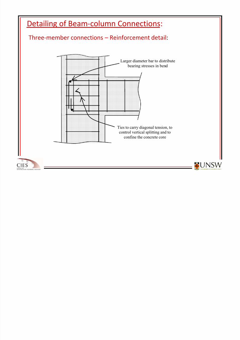
Three‐member
connections
– Reinforcement
detail:
Larger diameter bar to distribute
bearing stresses in bend
Ties to carry diagonal tension, tocontrol vertical splitting and to
confine the concrete core
Detailing of Beam‐column Connections:
8/20/2019 Detailing of Reinforcement in Concrete Structures 28 Aug 2012
http://slidepdf.com/reader/full/detailing-of-reinforcement-in-concrete-structures-28-aug-2012 69/82
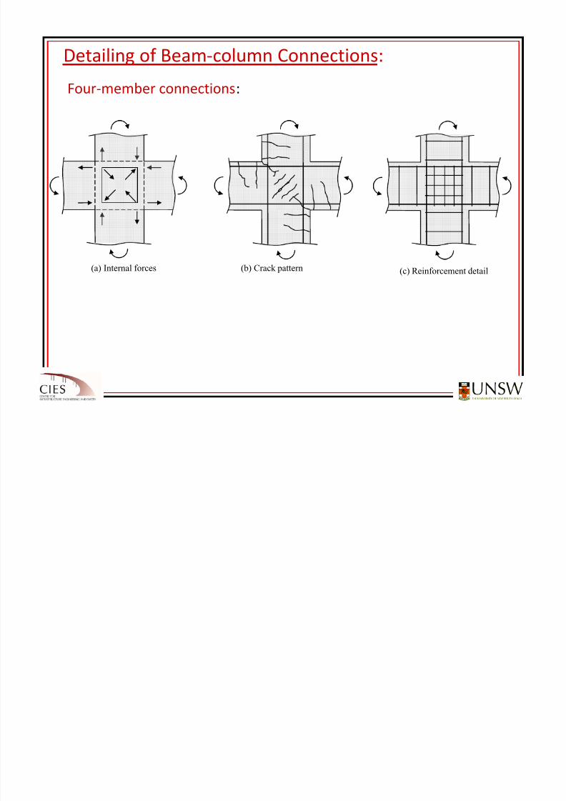
Four‐member
connections:
(a) Internal forces (b) Crack pattern (c) Reinforcement detail
Detailing of Corbels:
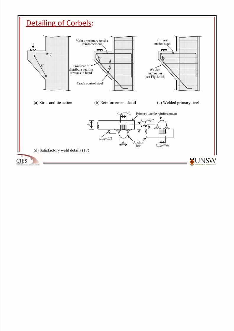
8/20/2019 Detailing of Reinforcement in Concrete Structures 28 Aug 2012
http://slidepdf.com/reader/full/detailing-of-reinforcement-in-concrete-structures-28-aug-2012 70/82
(a) Strut-and-tie action (b) Reinforcement detail (c) Welded primary steel
Crack control steel
Main or primary tensilereinforcement
Cross bar todistribute bearingstresses in bend
T
C
ℓ weld =¾d b
ℓ weld =¾d b
t weld =d b / 2
t weld =d b / 2
d b
d b
Primary tensile reinforcement
Anchor bar
(d) Satisfactory weld details (17)
Weldedanchor bar
(see Fig 8.46d)
Primarytension steel
Design of Corbels:
*
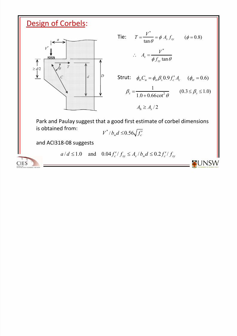
8/20/2019 Detailing of Reinforcement in Concrete Structures 28 Aug 2012
http://slidepdf.com/reader/full/detailing-of-reinforcement-in-concrete-structures-28-aug-2012 71/82
T
C
θ
d D
a
V *
Figure 8.47
≥ d/ 2
)8.0(tan
*
=== φ φ θ sy s f A
V T
θ φ tan
*
sy
s f
V A =∴
)6.0(9.0 =′= st cc s st u st A f C φ β φ φ
Tie:
Strut:
)0.13.0(cot66.00.1
12
≤≤+
= s s β θ
β
2/ sh A A ≥
Park and Paulay suggest that a good first estimate of corbel dimensions
is obtained from:
and ACI318‐08 suggests
cw f d bV ′≤ 56.0/*
sycw s syc f f d b A f f d a /2.0//04.0and 0.1/ ′≤≤′≤
Design of Corbels:
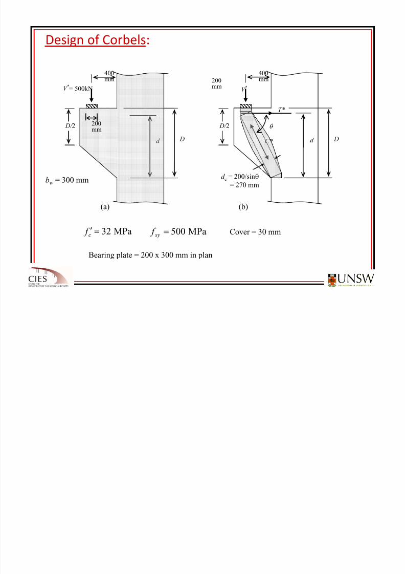
8/20/2019 Detailing of Reinforcement in Concrete Structures 28 Aug 2012
http://slidepdf.com/reader/full/detailing-of-reinforcement-in-concrete-structures-28-aug-2012 72/82
d D
400 mm
D/ 2
200 mm
T*
C*
(b)
θ
V *
d c=400 / sinθ
= 541 mm
d D
400mm
V *= 500kN
D/ 2 200mm
(a)
bw = 300 mm
MPa32=′c f MPa500= sy f Cover = 30 mm
Bearing plate = 200 x 300 mm in plan
d c = 200/sinθ= 270 mm
Design of Corbels:
8/20/2019 Detailing of Reinforcement in Concrete Structures 28 Aug 2012
http://slidepdf.com/reader/full/detailing-of-reinforcement-in-concrete-structures-28-aug-2012 73/82
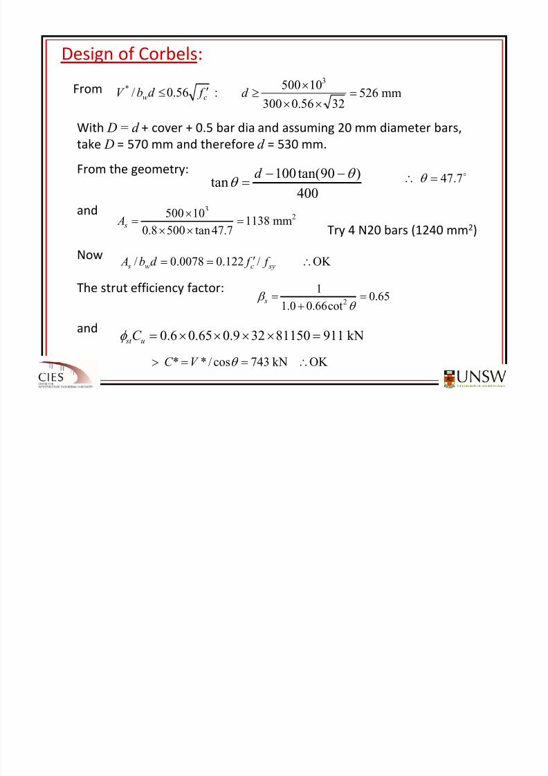
From :56.0/*cw f d bV ′≤ mm526
3256.030010500
3
=××
×≥d
With D = d + cover + 0.5 bar dia and assuming 20 mm diameter bars,
take D = 570 mm and therefore d = 530 mm.
From the geometry:
and
Try
4
N20
bars
(1240
mm2
)Now
The strut efficiency factor:
and
400
)90tan(100tan
θ θ
−−=
d o7.47=∴ θ
23
mm1138
7.47tan5008.0
10500=
××
×= s A
OK /122.00078.0/ ∴′== sycw s f f d b A
65.0
cot66.00.1
12 =
+
=θ
β s
kN91181150329.065.06.0 =××××=u st C φ
OK kN743cos/** ∴==> θ V C
Design of Corbels:
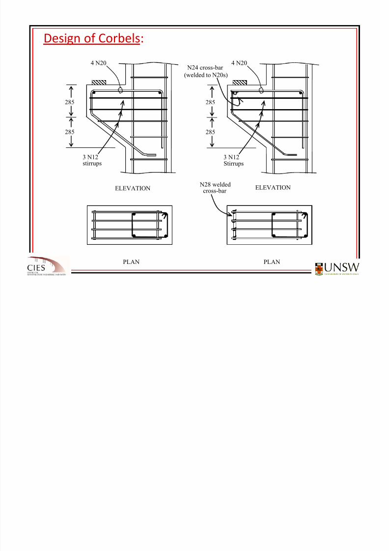
8/20/2019 Detailing of Reinforcement in Concrete Structures 28 Aug 2012
http://slidepdf.com/reader/full/detailing-of-reinforcement-in-concrete-structures-28-aug-2012 74/82
285
285
4 N20
3 N12stirrups
ELEVATION
PLAN
285
285
4 N20
3 N12Stirrups
N28 weldedcross-bar
ELEVATION
PLAN
N24 cross-bar
(welded to N20s)
JOINTS IN STRUCTURES:
8/20/2019 Detailing of Reinforcement in Concrete Structures 28 Aug 2012
http://slidepdf.com/reader/full/detailing-of-reinforcement-in-concrete-structures-28-aug-2012 75/82
Joints are
introduced
into
concrete
structures
for
two
main
reasons:
1) As stopping places in the concreting operation. The location of
these construction joints depends on the size and production
capacity of
the
construction
site
and
work
force;
2) To accommodate deformation (expansion, contraction, rotation,
settlement) without local distress or loss of integrity of the
structure. Such joints include:
control joints (contraction joints);
expansion joints;
structural joints (such as hinges, pin and roller joints);
shrinkage strips ; and
isolation joints.
The location of these joints depends on the anticipated
movements of the structure during its lifetime and the resulting
effects on structural behaviour.
8/20/2019 Detailing of Reinforcement in Concrete Structures 28 Aug 2012
http://slidepdf.com/reader/full/detailing-of-reinforcement-in-concrete-structures-28-aug-2012 76/82
8/20/2019 Detailing of Reinforcement in Concrete Structures 28 Aug 2012
http://slidepdf.com/reader/full/detailing-of-reinforcement-in-concrete-structures-28-aug-2012 77/82
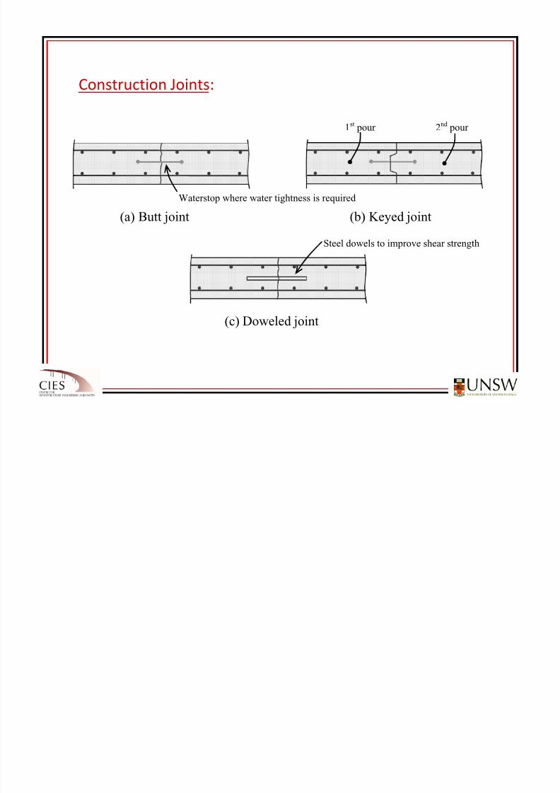
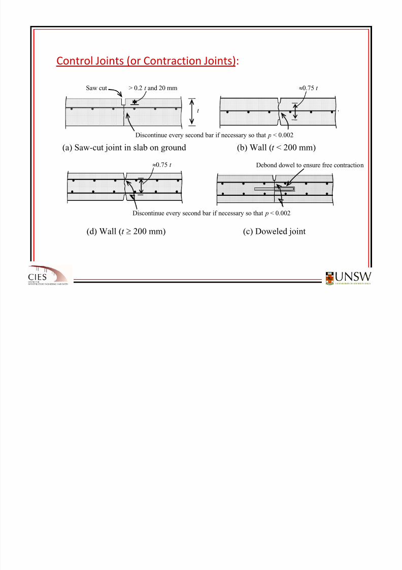
Control
Joints
(or
Contraction
Joints):
Debond dowel to ensure free contraction
Saw cut > 0.2 t and 20 mm ≈0.75 t
Discontinue every second bar if necessary so that p < 0.002
(a) Saw-cut joint in slab on ground (b) Wall (t < 200 mm)
(d) Wall (t ≥ 200 mm) (c) Doweled joint
t
≈0.75 t
Discontinue every second bar if necessary so that p < 0.002
8/20/2019 Detailing of Reinforcement in Concrete Structures 28 Aug 2012
http://slidepdf.com/reader/full/detailing-of-reinforcement-in-concrete-structures-28-aug-2012 78/82
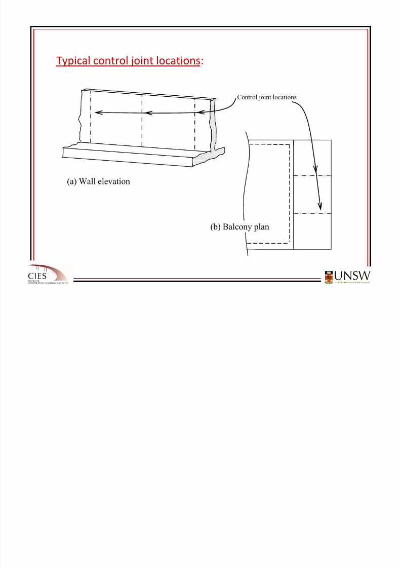
Typical
control
joint
locations:
Control joint locations
(a) Wall elevation
(b) Balcony plan
8/20/2019 Detailing of Reinforcement in Concrete Structures 28 Aug 2012
http://slidepdf.com/reader/full/detailing-of-reinforcement-in-concrete-structures-28-aug-2012 79/82
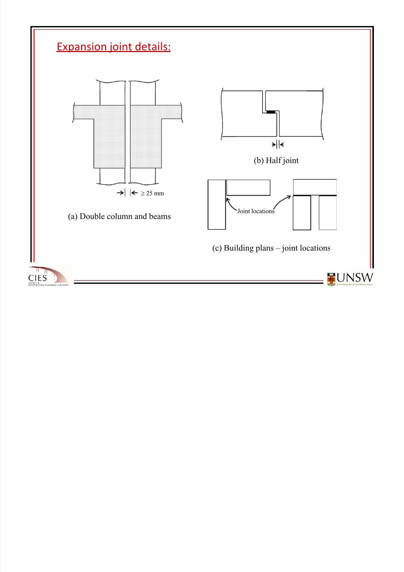
Expansion joint details:
8/20/2019 Detailing of Reinforcement in Concrete Structures 28 Aug 2012
http://slidepdf.com/reader/full/detailing-of-reinforcement-in-concrete-structures-28-aug-2012 80/82
≥ 25 mm
Joint locations(a) Double column and beams
(b) Half joint
(c) Building plans – joint locations
(a) Double column and beams
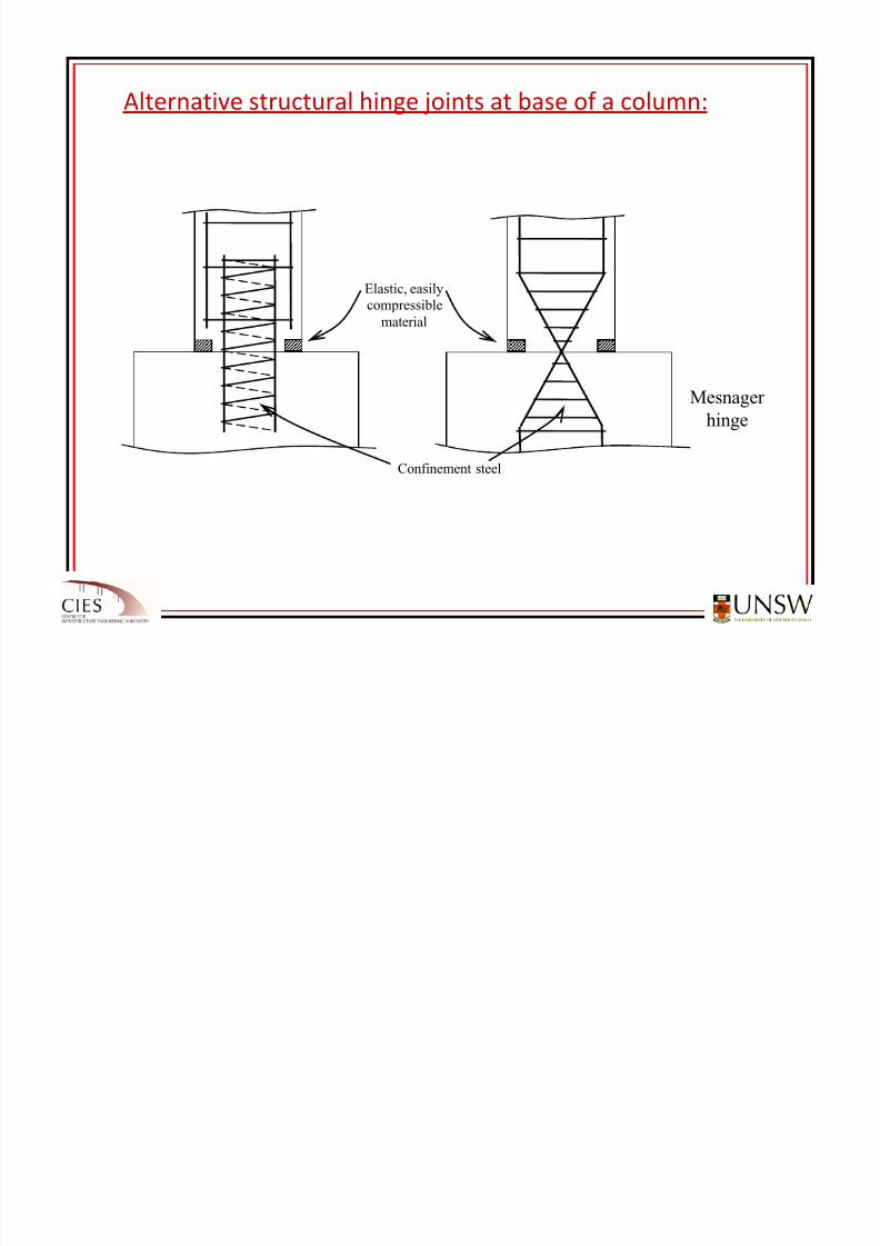
Alternative structural hinge joints at base of a column:
8/20/2019 Detailing of Reinforcement in Concrete Structures 28 Aug 2012
http://slidepdf.com/reader/full/detailing-of-reinforcement-in-concrete-structures-28-aug-2012 81/82
Elastic, easily
compressible
material
Mesnager
hinge
Confinement steel

8/20/2019 Detailing of Reinforcement in Concrete Structures 28 Aug 2012
http://slidepdf.com/reader/full/detailing-of-reinforcement-in-concrete-structures-28-aug-2012 82/82
THANKS FOR YOUR ATTENTION
ARE THERE ANY QUESTIONS ?