Embed Size (px)
Citation preview

Detailed baseline forbaseline for EEE in 100G
Mark Gustlin Hugh Barrass Mike Bennett AdamMark Gustlin, Hugh Barrass, Mike Bennett, Adam Healey, Velu Pillai, Matt Brown, Wael Diab
IEEE P802.3bj
IEEE 802.3bj – March, 2012, Kona, HiPresentation_ID 1
March, 2012
Contributors, reviewers and supporters
• David Chalupsky Intelp y• Valerie Maguire Siemon
D id Of lt J i• David Ofelt Juniper• Alexander Umnov Huawei• Pedro Vasallo U. Nebrija
2Please do not print!IEEE 802.3bj – March, 2012, Kona, Hi
Agendag
• January BaselineJanuary Baseline• Issues• PCS, state machines & functions• FEC, requirements• PMA, state machines & functions• Functions changes from 802 3ba• Functions, changes from 802.3ba• Questions…
3Please do not print!IEEE 802.3bj – March, 2012, Kona, Hi
Energy Efficient Ethernetgy
• January EEE Baseline – gustlin_02_0112.pdf• Introduces Rapid Alignment Markers• The next slides are the foundation of the EEE
baseline:– Slides 3 – 16, 19 – 22 from January, kept unchanged
• Further issues addressed in this presentation:– Updates to state machine (was slide 17)– Add fast-wake (introduced by barrass_01_0112.pdf)
Al id d l it (CAUI i t f )
4Please do not print!IEEE 802.3bj – March, 2012, Kona, Hi
– Also consider modularity (CAUI interface)
EEE for 100 Gb/s Overview
• This presentation will review the technical issues that need to be addressed in order to add EEE to a 100 Gb/s copper interfaces
• This will evolve into a baseline proposal over time• One significant issue has to do with the Alignment Marker lock
time, a proposal to address this concern is described• Details and examples of other considerations for EEE at 100
Gb/s are also exploredGb/s are also explored• This presentation assumes re-using Low Power Idle
5Please do not print!IEEE 802.3bj – March, 2012, Kona, Hi
EEE Overview
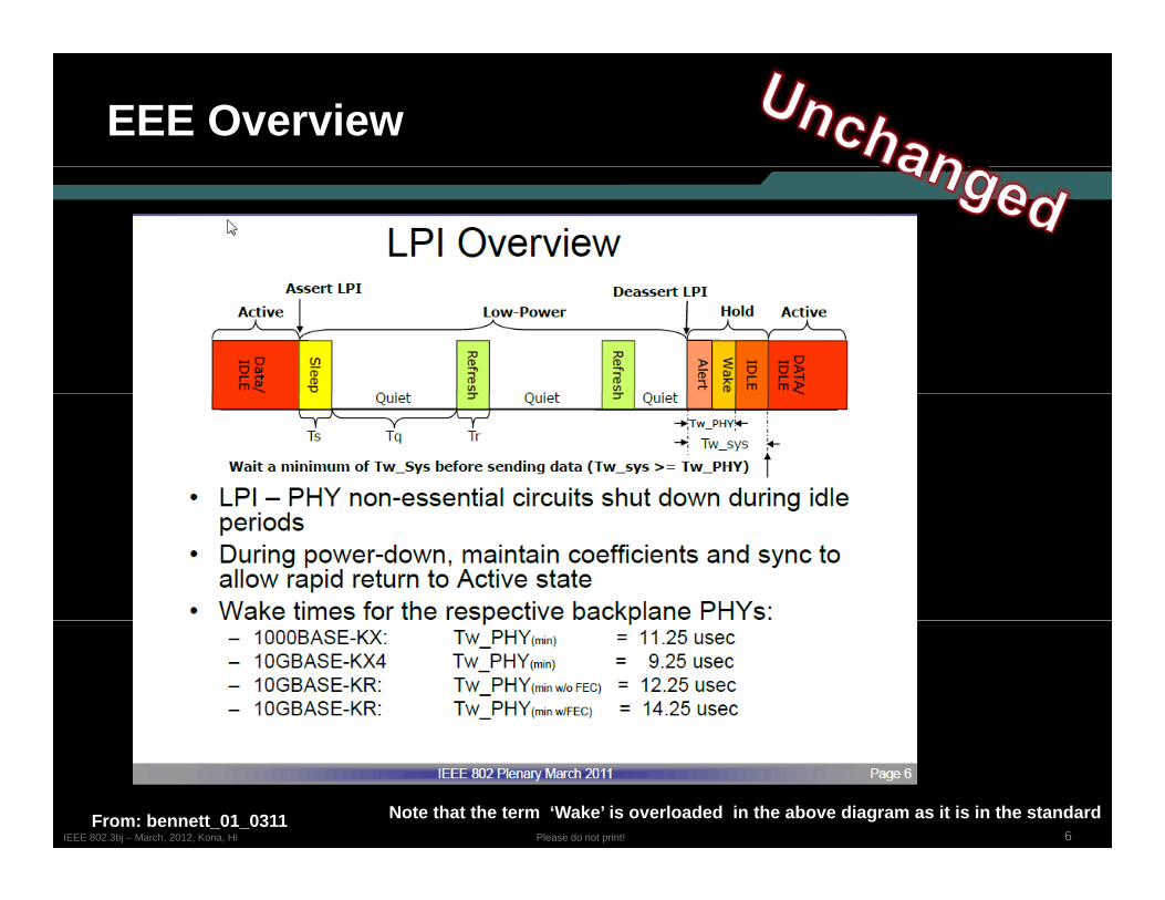
6Please do not print!IEEE 802.3bj – March, 2012, Kona, HiFrom: bennett_01_0311 Note that the term ‘Wake’ is overloaded in the above diagram as it is in the standard
EEE Overview
• Wake time range is 9 to 14usec for existing EEE PHYs• Note that the wake time does not scale down with speed even
though data accumulates faster at higher interface speeds• So for 100 Gb/s should we shoot for a wakeup time of < 5usec?
• Note that in 5 µs, 0.5Mb of data accumulates, per port
• Are there any concerns in the 100 Gb/s PCS that would prevent usAre there any concerns in the 100 Gb/s PCS that would prevent us from supporting a 5 usec or faster wakeup?
• Alignment marker lock is >> 5 µs, the next few slides look at this issue
7Please do not print!IEEE 802.3bj – March, 2012, Kona, Hi
Underlying Assumptions
• Many solutions can be proposed to solve the quick link bring-up issue depending on the assumptions that are madeissue, depending on the assumptions that are made
• For instance, if you assume that only the PMD lanes are powered down, and that the PCS and PMA stay powered and unchanged, then you could make some simplifying assumptions
• Skew change is very limited• But that might limit how much power savings could be achieved• If the PMD is powered off, then PCS lanes can move locations (due to
th b i ) d th f Ali t M k d d t fi dthe gearboxing), and therefore Alignment Markers are needed to find PCS locations
• In this paper is it assumed that the PCS, PMA and PMD can be powered down and therefore that:
• PCS lanes can move locations• A solution should handle the maximum skew as specified in
802.3ba
8Please do not print!IEEE 802.3bj – March, 2012, Kona, Hi
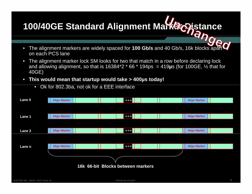
100/40GE Standard Alignment Marker Distance
• The alignment markers are widely spaced for 100 Gb/s and 40 Gb/s, 16k blocks apart on each PCS lane
• The alignment marker lock SM looks for two that match in a row before declaring lock• The alignment marker lock SM looks for two that match in a row before declaring lock and allowing alignment, so that is 16384*2 * 66 * 194ps = 419µs (for 100GE, ½ that for 40GE)
• This would mean that startup would take > 400µs today!Ok f 802 3b k f EEE i f• Ok for 802.3ba, not ok for a EEE interface
Lane 0 Align Marker Align Markero o o
Lane 1
Lane 2
Align Marker Align Markero o o
Align Marker Align Markero o o
Lane n Align Marker Align Markero o o
9Please do not print!IEEE 802.3bj – March, 2012, Kona, Hi
16k 66-bit Blocks between markers
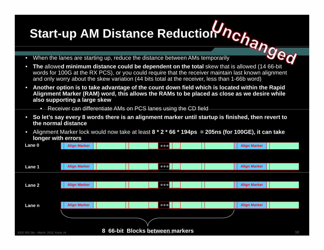
Start-up AM Distance Reduction
• When the lanes are starting up, reduce the distance between AMs temporarily• The allowed minimum distance could be dependent on the total skew that is allowed (14 66-bit
words for 100G at the RX PCS), or you could require that the receiver maintain last known alignment and only worry about the skew variation (44 bits total at the receiver less than 1 66b word)and only worry about the skew variation (44 bits total at the receiver, less than 1-66b word)
• Another option is to take advantage of the count down field which is located within the Rapid Alignment Marker (RAM) word, this allows the RAMs to be placed as close as we desire while also supporting a large skew
• Receiver can differentiate AMs on PCS lanes using the CD fieldReceiver can differentiate AMs on PCS lanes using the CD field• So let’s say every 8 words there is an alignment marker until startup is finished, then revert to
the normal distance• Alignment Marker lock would now take at least 8 * 2 * 66 * 194ps = 205ns (for 100GE), it can take
longer with errorsgLane 0
Lane 1
Align Marker Align Markero o o
Align Marker Align Markero o o
Lane 2
L
Align Marker Align Markero o o
Ali M k Ali M k
10Please do not print!IEEE 802.3bj – March, 2012, Kona, Hi
Lane n Align Marker Align Markero o o
8 66-bit Blocks between markers
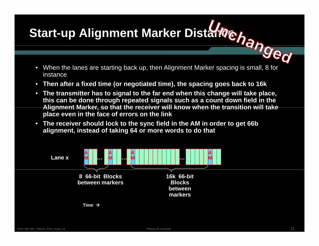
Start-up Alignment Marker Distance
• When the lanes are starting back up, then Alignment Marker spacing is small, 8 for instanceinstance
• Then after a fixed time (or negotiated time), the spacing goes back to 16k• The transmitter has to signal to the far end when this change will take place,
this can be done through repeated signals such as a count down field in the Alignment Marker so that the receiver will know when the transition will takeAlignment Marker, so that the receiver will know when the transition will take place even in the face of errors on the link
• The receiver should lock to the sync field in the AM in order to get 66balignment, instead of taking 64 or more words to do that
Lane x …AM
AM
AM…
AM…
8 66-bit Blocks between markers
16k 66-bit Blocks
between markers
11Please do not print!IEEE 802.3bj – March, 2012, Kona, Hi
Time
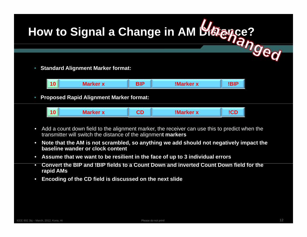
How to Signal a Change in AM Distance?
• Standard Alignment Marker format:
10 Marker x BIP !Marker x !BIP
• Proposed Rapid Alignment Marker format:
• Add a count down field to the alignment marker, the receiver can use this to predict when the transmitter ill s itch the distance of the alignment markers
10 Marker x CD !Marker x !CD
transmitter will switch the distance of the alignment markers• Note that the AM is not scrambled, so anything we add should not negatively impact the
baseline wander or clock content• Assume that we want to be resilient in the face of up to 3 individual errors
C t th BIP d !BIP fi ld t C t D d i t d C t D fi ld f th• Convert the BIP and !BIP fields to a Count Down and inverted Count Down field for the rapid AMs
• Encoding of the CD field is discussed on the next slide
12Please do not print!IEEE 802.3bj – March, 2012, Kona, Hi
Count Down Field Encoding
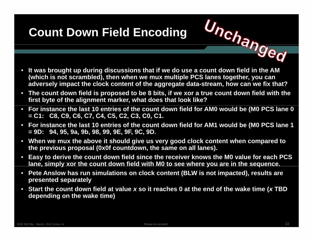
• It was brought up during discussions that if we do use a count down field in the AM ( hi h i t bl d) th h lti l PCS l t th(which is not scrambled), then when we mux multiple PCS lanes together, you can adversely impact the clock content of the aggregate data-stream, how can we fix that?
• The count down field is proposed to be 8 bits, if we xor a true count down field with the first byte of the alignment marker, what does that look like?
• For instance the last 10 entries of the count down field for AM0 would be (M0 PCS lane 0 = C1: C8, C9, C6, C7, C4, C5, C2, C3, C0, C1.
• For instance the last 10 entries of the count down field for AM1 would be (M0 PCS lane 1 = 9D: 94, 95, 9a, 9b, 98, 99, 9E, 9F, 9C, 9D.
• When we mux the above it should give us very good clock content when compared to the previous proposal (0x0f countdown, the same on all lanes).
• Easy to derive the count down field since the receiver knows the M0 value for each PCS lane, simply xor the count down field with M0 to see where you are in the sequence., p y y q
• Pete Anslow has run simulations on clock content (BLW is not impacted), results are presented separately
• Start the count down field at value x so it reaches 0 at the end of the wake time (x TBD depending on the wake time)
13Please do not print!IEEE 802.3bj – March, 2012, Kona, Hi
depending on the wake time)
Start-up Alignment Marker Distance
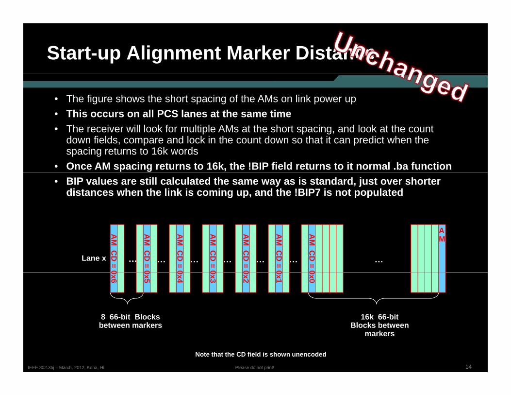
• The figure shows the short spacing of the AMs on link power up• This occurs on all PCS lanes at the same time• The receiver will look for multiple AMs at the short spacing, and look at the count
down fields, compare and lock in the count down so that it can predict when the spacing returns to 16k words
• Once AM spacing returns to 16k, the !BIP field returns to it normal .ba function• BIP values are still calculated the same way as is standard, just over shorter
distances when the link is coming up, and the !BIP7 is not populated
Lane x … … … … …
AM
CD
= 0
…
AM
…
AM
CD
= 0
AM
CD
= 0
AM
CD
= 0
AM
CD
= 0
AM
CD
= 0
AM
CD
= 0
8 66-bit Blocks 16k 66-bit
0x0
0x1
0x2
0x3
0x4
0x5
0x6
14Please do not print!IEEE 802.3bj – March, 2012, Kona, Hi
between markers Blocks between markers
Note that the CD field is shown unencoded
Block Alignment with AMs
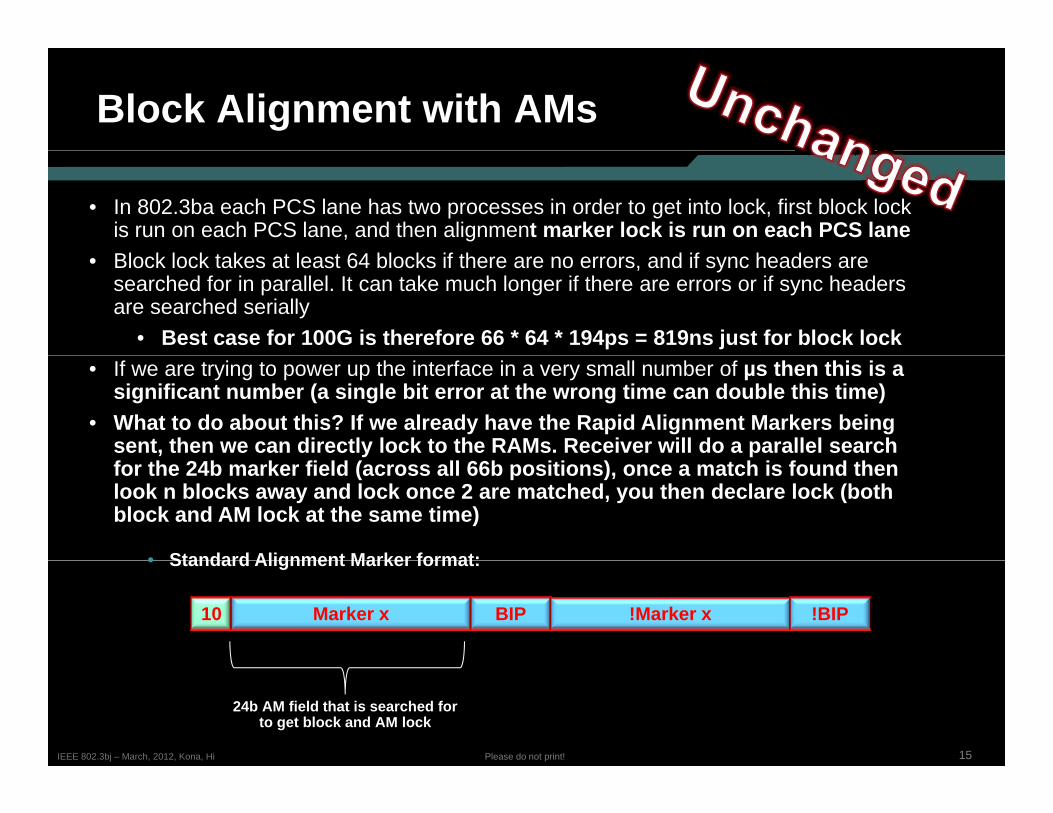
• In 802.3ba each PCS lane has two processes in order to get into lock, first block lock is run on each PCS lane, and then alignment marker lock is run on each PCS laneBl k l k k l 64 bl k if h d if h d• Block lock takes at least 64 blocks if there are no errors, and if sync headers are searched for in parallel. It can take much longer if there are errors or if sync headers are searched serially
• Best case for 100G is therefore 66 * 64 * 194ps = 819ns just for block lock• If we are trying to power up the interface in a very small number of µs then this is a
significant number (a single bit error at the wrong time can double this time)• What to do about this? If we already have the Rapid Alignment Markers being
sent, then we can directly lock to the RAMs. Receiver will do a parallel search for the 24b marker field (across all 66b positions), once a match is found then look n blocks away and lock once 2 are matched, you then declare lock (both block and AM lock at the same time)
• Standard Alignment Marker format:
10 Marker x BIP !Marker x !BIP
• Standard Alignment Marker format:
15Please do not print!IEEE 802.3bj – March, 2012, Kona, Hi
24b AM field that is searched forto get block and AM lock
Count Down Field Sync
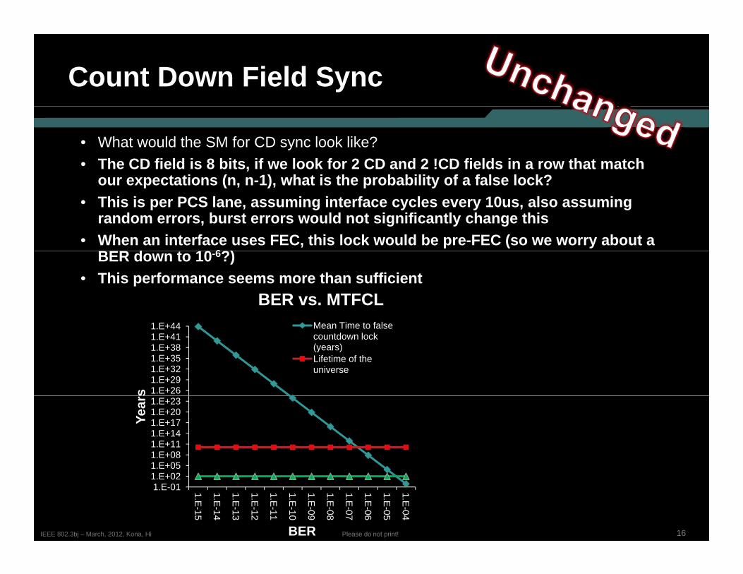
• What would the SM for CD sync look like?• The CD field is 8 bits, if we look for 2 CD and 2 !CD fields in a row that match
our expectations (n n 1) what is the probability of a false lock?our expectations (n, n-1), what is the probability of a false lock?• This is per PCS lane, assuming interface cycles every 10us, also assuming
random errors, burst errors would not significantly change this• When an interface uses FEC, this lock would be pre-FEC (so we worry about a
BER d t 10 6?)BER down to 10-6?)• This performance seems more than sufficient
1 E 44
BER vs. MTFCLM Ti t f l
1.E+261.E+291.E+321.E+351.E+381.E+411.E+44
s
Mean Time to false countdown lock (years) Lifetime of the universe
1.E+051.E+081.E+111.E+141.E+171.E+201.E+23
Year
s
16Please do not print!IEEE 802.3bj – March, 2012, Kona, Hi
1.E-011.E+021.E 05
1.E-15
1.E-14
1.E-13
1.E-12
1.E-11
1.E-10
1.E-09
1.E-08
1.E-07
1.E-06
1.E-05
1.E-04
BER
Link Start-up
• When a device first powers up, it will power up sending 802.3ba AMs, 16k apart• What if a fault causes the receiver to miss startup, and it first sees AMs on a
power bring up from LPI?• State Machines already handle these kind of issues for 802.3az EEE, so
the same thing would apply, the SM would have timeouts to handle the g pp y,error cases, no need to do anything else.
17Please do not print!IEEE 802.3bj – March, 2012, Kona, Hi
Data ‘Randomness’
• There was a lot of work done during the 802.3ba project on baseline wander and clock content of the 100 Gb/s data stream and various sub 100 Gb/s lanesand clock content of the 100 Gb/s data stream and various sub 100 Gb/s lanes (10G CAUI lanes, 25G PMD lanes etc.) in order to ensure that the characteristics of a given serial data stream are good, see:
http://www.ieee802.org/3/ba/public/jan08/anslow_01_0108.pdfhttp://www.ieee802.org/3/ba/public/nov08/anslow_06_1108.pdf
• When we send RAMs, does that impact the baseline wander or clock content negatively?
• Pete Anslow has run simulations see his separate presentation• Pete Anslow has run simulations, see his separate presentation• There is some concern with when the lanes are being powered up, will the
randomness of the data being sent at that time be sufficient to quickly train the receivers?
Si l ti d t b d t i thi• Simulations need to be run determine this• The count down field is a new concept to this protocol, if you bit multiplex
multiple streams together with an 802.3ba PMA, how will this impact the clock content (given that the count down field is not scrambled)?
18Please do not print!IEEE 802.3bj – March, 2012, Kona, Hi
• Pete Anslow has run simulations, see his separate presentation
Room for Rapid AMs?
• In 802.3ba the Alignment Markers are sent very infrequently, every 16k blocks on each PCS Lane
• This allows room for the AMs to be added into the data stream by deleting Idles periodically, just as is done for clock compensation
• If we send AMs rapidly, then we can still delete idles in order to send AMs? p y,• Yes this works since rapid AMs are only sent on link re-start when
transitioning out of LPI, so only LPI or Idle is being sent at that time• Proposal is that Either Idles or LPIs can be deleted to add in the AMs
19Please do not print!IEEE 802.3bj – March, 2012, Kona, Hi
FEC and EEE
• How would 802.3bj FEC impact EEE bringup time?
• In the original EEE they did things such as have a scrambler bypass• In the original EEE, they did things such as have a scrambler bypass so that the receiver can quickly lock up to a known FEC location
• For EEE and 100G, what do we need to do?
• The current direction of this task force on FEC is some sort of transcoding and then stripping FEC across the lanes. Also there is the plan to align the alignment markers to the beginning of the FEC block
20Please do not print!IEEE 802.3bj – March, 2012, Kona, Hi
RAMs and EEEExample only – to be modified
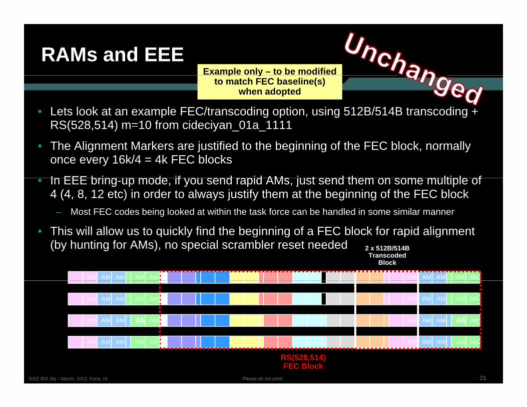
• Lets look at an example FEC/transcoding option, using 512B/514B transcoding + RS(528 514) m=10 from cideciyan 01a 1111
p yto match FEC baseline(s)
when adopted
RS(528,514) m 10 from cideciyan_01a_1111
• The Alignment Markers are justified to the beginning of the FEC block, normally once every 16k/4 = 4k FEC blocks
I EEE b i d if d id AM j t d th lti l f• In EEE bring-up mode, if you send rapid AMs, just send them on some multiple of 4 (4, 8, 12 etc) in order to always justify them at the beginning of the FEC block
– Most FEC codes being looked at within the task force can be handled in some similar manner
This will allow us to quickly find the beginning of a FEC block for rapid alignment
AM AMAM AMAM
2 x 512B/514BTranscoded
Block
• This will allow us to quickly find the beginning of a FEC block for rapid alignment (by hunting for AMs), no special scrambler reset needed
AM AMAM AMAM
AM AMAM AMAM
AM AMAM AMAM
AM AMAM AMAM
AM AMAM AMAM
21Please do not print!IEEE 802.3bj – March, 2012, Kona, Hi
AM AMAM AMAM
RS(528,514)FEC Block
AM AMAM AMAM
Document Changes Required
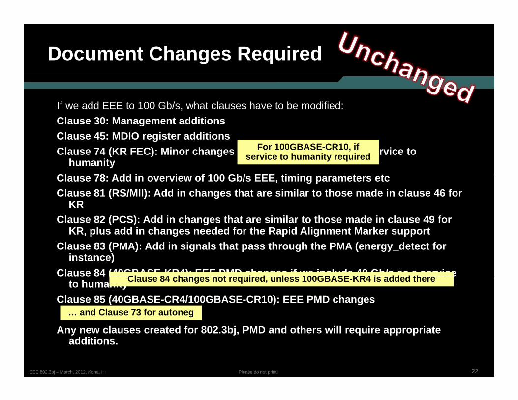
If we add EEE to 100 Gb/s, what clauses have to be modified:Clause 30: Management additions C ause 30 a age e t add t o sClause 45: MDIO register additionsClause 74 (KR FEC): Minor changes if we include 40 Gb/s as a service to
humanityCl 78 Add i i f 100 Gb/ EEE ti i t t
For 100GBASE-CR10, if service to humanity required
Clause 78: Add in overview of 100 Gb/s EEE, timing parameters etcClause 81 (RS/MII): Add in changes that are similar to those made in clause 46 for
KRClause 82 (PCS): Add in changes that are similar to those made in clause 49 for ( ) g
KR, plus add in changes needed for the Rapid Alignment Marker supportClause 83 (PMA): Add in signals that pass through the PMA (energy_detect for
instance)Clause 84 (40GBASE-KR4): EEE PMD changes if we include 40 Gb/s as a serviceCl 84 h t i d l 100GBASE KR4 i dd d thClause 84 (40GBASE KR4): EEE PMD changes if we include 40 Gb/s as a service
to humanityClause 85 (40GBASE-CR4/100GBASE-CR10): EEE PMD changes
A l t d f 802 3bj PMD d th ill i i t
Clause 84 changes not required, unless 100GBASE-KR4 is added there
… and Clause 73 for autoneg
22Please do not print!IEEE 802.3bj – March, 2012, Kona, Hi
Any new clauses created for 802.3bj, PMD and others will require appropriate additions.
Recap – Rapid Alignment Markersp p g
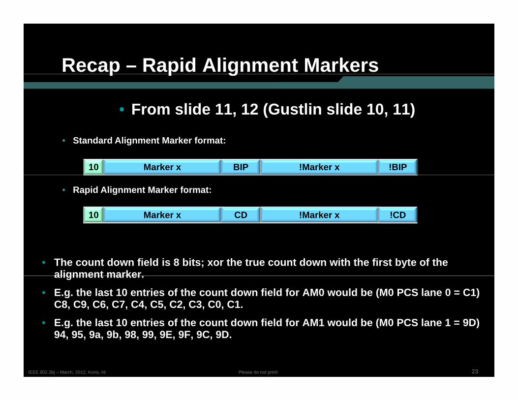
• From slide 11, 12 (Gustlin slide 10, 11)
10 Marker x BIP !Marker x !BIP
• Standard Alignment Marker format:
• Rapid Alignment Marker format:
10 Marker x CD !Marker x !CD
• The count down field is 8 bits; xor the true count down with the first byte of the alignment markeralignment marker.
• E.g. the last 10 entries of the count down field for AM0 would be (M0 PCS lane 0 = C1)C8, C9, C6, C7, C4, C5, C2, C3, C0, C1.
• E.g. the last 10 entries of the count down field for AM1 would be (M0 PCS lane 1 = 9D)
23Please do not print!IEEE 802.3bj – March, 2012, Kona, Hi
g t e ast 0 e t es o t e cou t do e d o ou d be ( 0 CS a e 9 )94, 95, 9a, 9b, 98, 99, 9E, 9F, 9C, 9D.
Recap – RAM spacingp p g
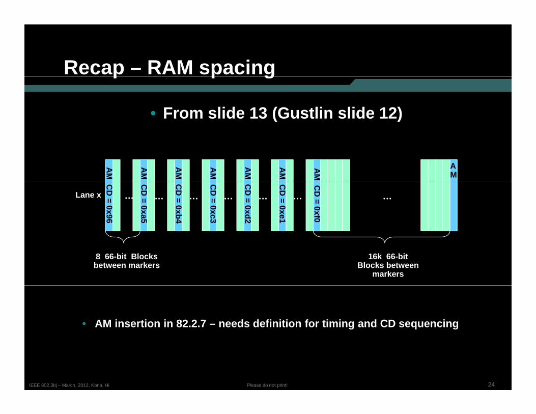
• From slide 13 (Gustlin slide 12)
AM A
M
AM
AMAM
AMAM
AM
Lane x … … … … …
CD
= 0xf0
… …
CD
= 0xe1
CD
= 0xd2
CD
= 0xc3
CD
= 0xb4
CD
= 0xa5
CD
= 0x96
8 66-bit Blocks between markers
16k 66-bit Blocks between
markers
• AM insertion in 82.2.7 – needs definition for timing and CD sequencing
24Please do not print!IEEE 802.3bj – March, 2012, Kona, Hi
Agendag
• January BaselineJanuary Baseline• Issues• PCS, state machines & functions• FEC, requirements• PMA, state machines & functions• Functions changes from 802 3ba• Functions, changes from 802.3ba• Questions…
25Please do not print!IEEE 802.3bj – March, 2012, Kona, Hi
Problem with modularityy
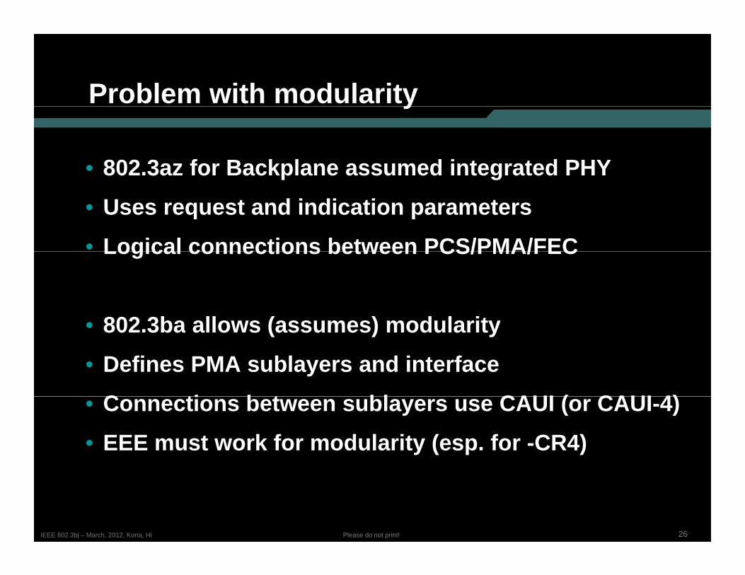
• 802.3az for Backplane assumed integrated PHYp g• Uses request and indication parameters• Logical connections between PCS/PMA/FECLogical connections between PCS/PMA/FEC
• 802 3ba allows (assumes) modularity• 802.3ba allows (assumes) modularity• Defines PMA sublayers and interface
C ti b t bl CAUI ( CAUI 4)• Connections between sublayers use CAUI (or CAUI-4)• EEE must work for modularity (esp. for -CR4)
26Please do not print!IEEE 802.3bj – March, 2012, Kona, Hi
CAUI shutdown
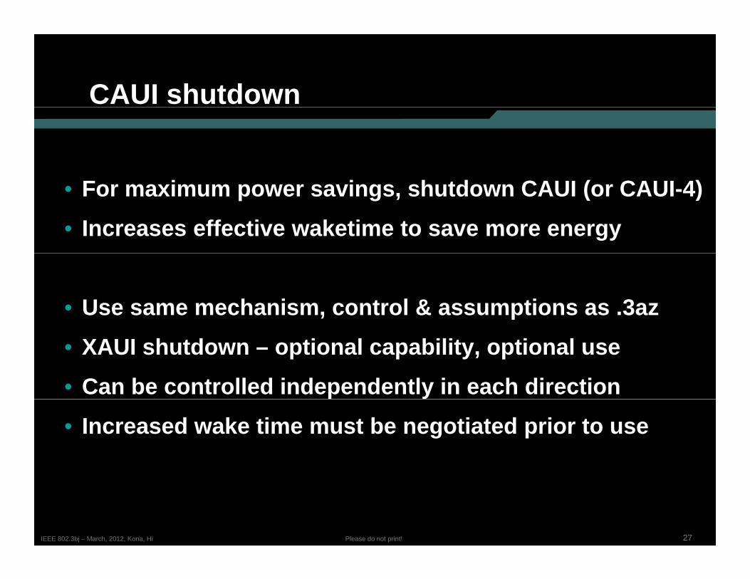
F i i h d CAUI ( CAUI 4)• For maximum power savings, shutdown CAUI (or CAUI-4)• Increases effective waketime to save more energy
• Use same mechanism, control & assumptions as .3az• XAUI shutdown – optional capability, optional use• Can be controlled independently in each direction• Increased wake time must be negotiated prior to use
27Please do not print!IEEE 802.3bj – March, 2012, Kona, Hi
Fast-Wake implicationsp
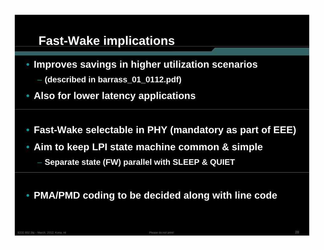
• Improves savings in higher utilization scenarios(d ib d i b 01 0112 df)– (described in barrass_01_0112.pdf)
• Also for lower latency applications
• Fast-Wake selectable in PHY (mandatory as part of EEE)• Aim to keep LPI state machine common & simple
– Separate state (FW) parallel with SLEEP & QUIET
• PMA/PMD coding to be decided along with line code
28Please do not print!IEEE 802.3bj – March, 2012, Kona, Hi
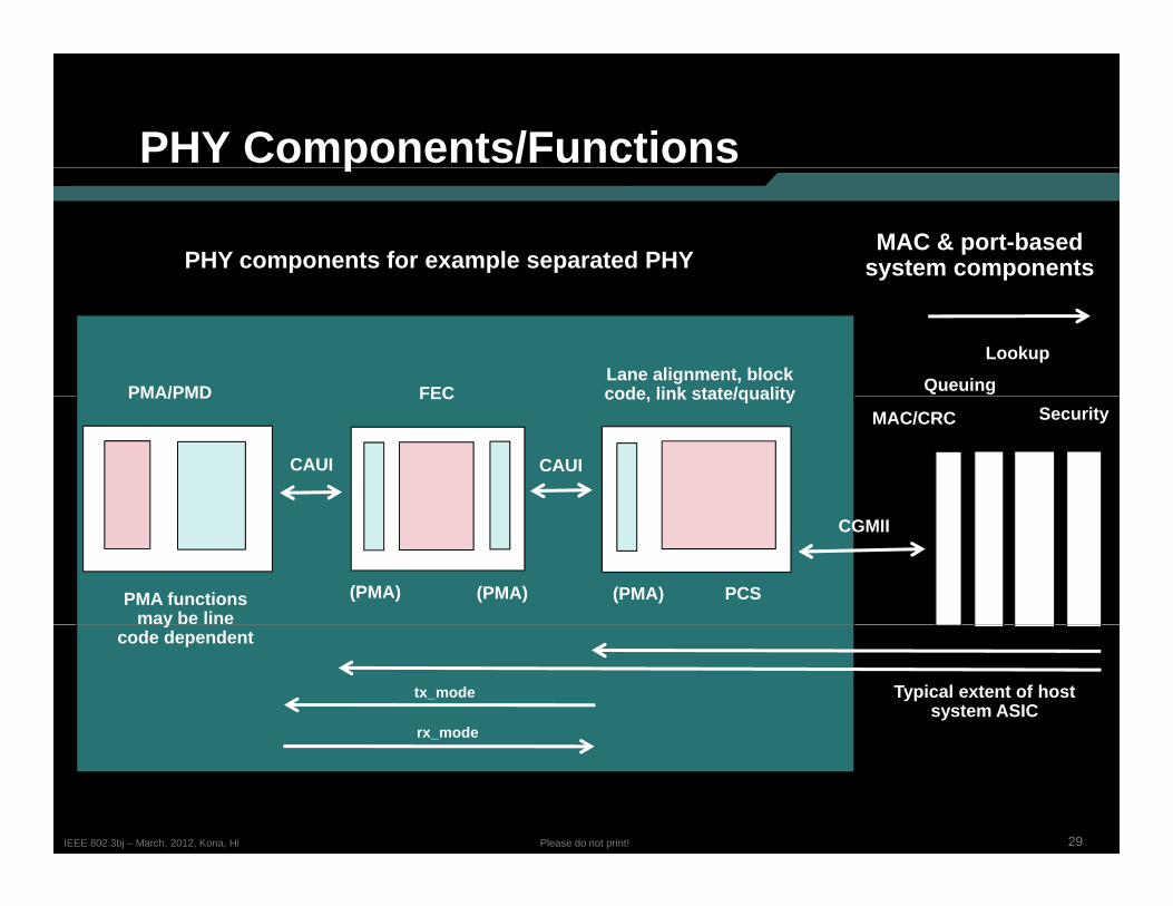
PHY Components/Functionsp
PHY components for example separated PHYMAC & port-based
system components
Lane alignment, block code link state/qualityFEC Queuing
Lookup
PMA/PMD code, link state/qualityFECMAC/CRC Security
PMA/PMD
CAUICAUI
PMA functions may be line
PCS(PMA)
CGMII
(PMA)(PMA)y
code dependent
Typical extent of host system ASIC
tx_mode
rx mode
29Please do not print!IEEE 802.3bj – March, 2012, Kona, Hi
_
Agendag
• January BaselineJanuary Baseline• Issues• PCS, state machines & functions• FEC, requirements• PMA, state machines & functions• Functions changes from 802 3ba• Functions, changes from 802.3ba• Questions…
30Please do not print!IEEE 802.3bj – March, 2012, Kona, Hi
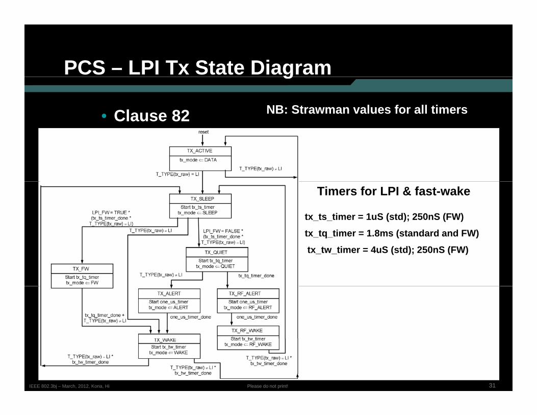
PCS – LPI Tx State Diagramg
• Clause 82 NB: Strawman values for all timers
Timers for LPI & fast-wake
tx_ts_timer = 1uS (std); 250nS (FW)tx tq timer = 1 8ms (standard and FW)tx_tq_timer = 1.8ms (standard and FW)
tx_tw_timer = 4uS (std); 250nS (FW)
31Please do not print!IEEE 802.3bj – March, 2012, Kona, Hi
Signaling tx_mode across CAUIg g _
• A mechanism must be defined to signal the tx_modeparameter across the CAUI from the PCS to the PMA/PMD
32Please do not print!IEEE 802.3bj – March, 2012, Kona, Hi
PCS – LPI Rx State Diagramg
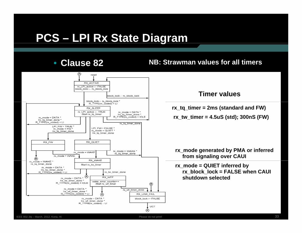
• Clause 82 NB: Strawman values for all timers
Timer values
rx_tq_timer = 2ms (standard and FW)
rx_tw_timer = 4.5uS (std); 300nS (FW)
rx_mode generated by PMA or inferred from signaling over CAUI
rx_mode = QUIET inferred by rx_block_lock = FALSE when CAUIshutdown selected
33Please do not print!IEEE 802.3bj – March, 2012, Kona, Hi
Signaling rx_mode across CAUIg g _
• A mechanism must be defined to signal the rx_modeparameter (or the state of the received signal) across the CAUI from the PMA/PMD to the PCS
34Please do not print!IEEE 802.3bj – March, 2012, Kona, Hi
Other PCS function changesg
• Similar to 802.3az Clause 49
• Control code definitions – 82 2 3• Control code definitions – 82.2.3• Transmit and receive state diagrams – 82-14, 82-15
Block lock and BER monitor 82 10 82 13• Block lock and BER monitor – 82-10, 82-13
• AM lock state diagram – add new definition (or diagram) for RAM lock
• Modified definition for am lock may be needed for
35Please do not print!IEEE 802.3bj – March, 2012, Kona, Hi
• Modified definition for am_lock may be needed for EEE (similar to block_lock)
Agendag
• January BaselineJanuary Baseline• Issues• PCS, state machines & functions• FEC, requirements• PMA, state machines & functions• Functions changes from 802 3ba• Functions, changes from 802.3ba• Questions…
36Please do not print!IEEE 802.3bj – March, 2012, Kona, Hi
FEC – Needs to be defined
• Dependent upon choice of FEC baseline…
• RAM alignment to the FEC frame• Start of FEC block relative to restoration of normal AMs
• Any special behavior of FEC for EEE
37Please do not print!IEEE 802.3bj – March, 2012, Kona, Hi
Agendag
• January BaselineJanuary Baseline• Issues• PCS, state machines & functions• FEC, requirements• PMA, state machines & functions• Functions changes from 802 3ba• Functions, changes from 802.3ba• Questions…
38Please do not print!IEEE 802.3bj – March, 2012, Kona, Hi
PMA/PMD – transmit functions
• An integrated PMA can use tx_mode parameters directly• Signaling across CAUI to be defined
• Based on tx_mode – PMA/PMD transmission changes– DATA/SLEEP/WAKE – normal behavior;– ALERT - send alert signal;– FW – send PMA-specific pattern (TBD);– QUIET – disable Tx– Requirements for PMA/PMD signaling depend on chosen line
code (etc.)
39Please do not print!IEEE 802.3bj – March, 2012, Kona, Hi
( )
PMA/PMD – receive functions
• Infer rx_mode from incoming signal:– Receiving normal AMs, or RAMs = DATA/SLEEP/WAKE– Receiving no signal = QUIET; alert signal = ALERT; specific
signaling = FW
• An integrated PMA can signal receive state to PCS• An integrated PMA can signal receive state to PCS directly
• Otherwise, code for signaling across CAUI - TBD
40Please do not print!IEEE 802.3bj – March, 2012, Kona, Hi
Otherwise, code for signaling across CAUI TBD
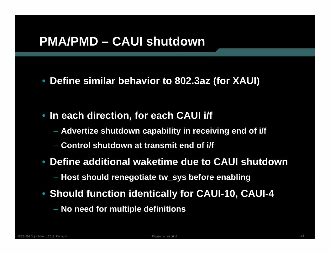
PMA/PMD – CAUI shutdown
Define similar behavior to 802 3az (for XAUI)• Define similar behavior to 802.3az (for XAUI)
• In each direction, for each CAUI i/f– Advertize shutdown capability in receiving end of i/f
C t l h td t t it d f i/f– Control shutdown at transmit end of i/f
• Define additional waketime due to CAUI shutdownH t h ld ti t t b f bli– Host should renegotiate tw_sys before enabling
• Should function identically for CAUI-10, CAUI-4N d f lti l d fi iti
41Please do not print!IEEE 802.3bj – March, 2012, Kona, Hi
– No need for multiple definitions
Agendag
• January BaselineJanuary Baseline• Issues• PCS, state machines & functions• FEC, requirements• PMA, state machines & functions• Functions changes from 802 3ba• Functions, changes from 802.3ba• Questions…
42Please do not print!IEEE 802.3bj – March, 2012, Kona, Hi
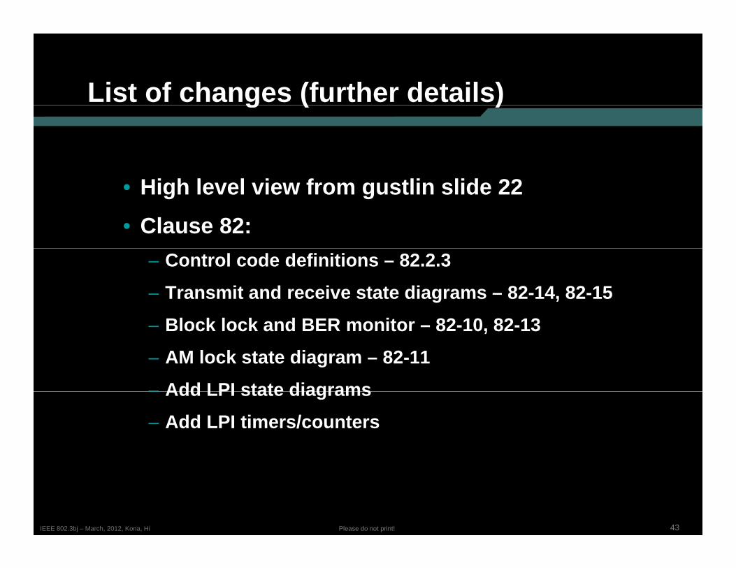
List of changes (further details)g ( )
• High level view from gustlin slide 22• Clause 82:
– Control code definitions – 82.2.3– Transmit and receive state diagrams – 82-14, 82-15
Bl k l k d BER it 82 10 82 13– Block lock and BER monitor – 82-10, 82-13– AM lock state diagram – 82-11– Add LPI state diagrams– Add LPI state diagrams– Add LPI timers/counters
43Please do not print!IEEE 802.3bj – March, 2012, Kona, Hi
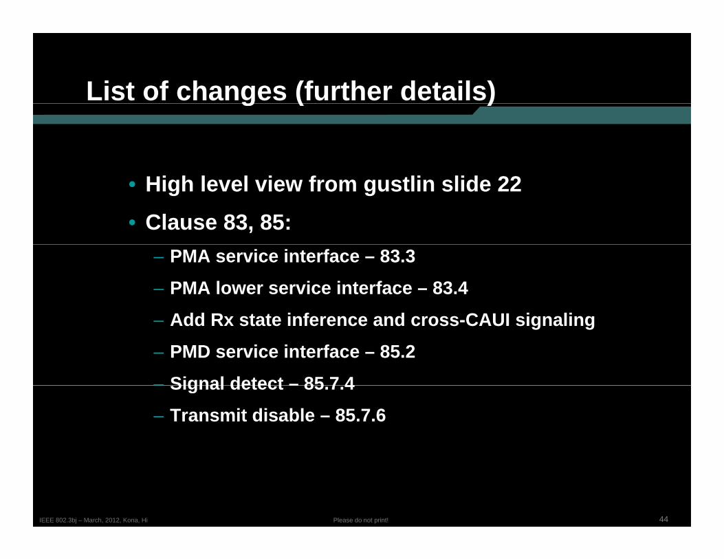
List of changes (further details)g ( )
• High level view from gustlin slide 22• Clause 83, 85:
– PMA service interface – 83.3– PMA lower service interface – 83.4
Add R t t i f d CAUI i li– Add Rx state inference and cross-CAUI signaling– PMD service interface – 85.2– Signal detect – 85 7 4– Signal detect – 85.7.4– Transmit disable – 85.7.6
44Please do not print!IEEE 802.3bj – March, 2012, Kona, Hi
Agendag
• January BaselineJanuary Baseline• Issues• PCS, state machines & functions• FEC, requirements• PMA, state machines & functions• Functions changes from 802 3ba• Functions, changes from 802.3ba• Questions…
45Please do not print!IEEE 802.3bj – March, 2012, Kona, Hi


![Energy XT PRO BaseLine Application [A00003xx-A00013xx]mosinv.ru/Documentation/XT-PRO/8MA10073 EXT Pro Baseline... · Energy XT PRO BaseLine Application [A00003xx-A00013xx] BaseLine](https://img.pdfslide.us/doc/110x75/5ca5dcdf88c99388188d3802/energy-xt-pro-baseline-application-a00003xx-a00013xx-ext-pro-baseline-energy.jpg)