Embed Size (px)
Citation preview
Drawing Title:
© DORMA USA Inc. Subject to Change Without Notice. Date: 17-NOV-2015
924 Sherwood Dr. Lake Bluff, IL 60044 Phone: 800-523-8483
ED250_IG_PAIR_CENTER_HUNG
SHAFT SEALS
GASKET
RECOMMENDED MINIMUM
1/2" [13] x 10" [254] THRESHOLD
BY OTHERS
FINISHED FLOOR SURFACE
PACKAGE WIDTH (DOOR OPENING WIDTH + 1/2" [13])
CEMENT CASE COVER
(ACCESS REQUIRED)
REF. 1 3/4" [44]
DOOR WIDTH
TOP OF COVER
FINISHED FLOOR
POURSTONE
CEMENT CASE
FLOOR SLAB
35 1/2" [902] CEMENT CASE
2
2
11
DETAIL A
1" [25]
MIN.
CONCRETE
EXTERIOR ELEVATION
ED250-IG CENTER HUNG OPERATOR
SECTION 1
ED250-IG CENTER HUNG OPERATOR
SECTION 2
ED250-IG CENTER HUNG OPERATOR
7" [178]
CEMENT CASE
1/4" [6]
UNDER JAMB
SPINDLE CENTERLINE
TOP OF COVER 1/4" [6] MINIMUM
BELOW FINISHED FLOOR
FINISHED
FLOOR
FOR 1/4-20 MACHINE SCREWS USE No.7 DRILL
FOR No.14 WOOD SCREWS USE 5/32" DRILL
FIVE (5) HOLES IN DOOR
ALUMINUM DOOR SHOWN
DETAIL A
ED250-IG CENTER PIVOT ARM
SECTION 3
ED250-IG CENTER PIVOT ARM
3 1/2" [89]
CASE TO
DOOR PIVOT
33
2 3/4" [70]
SPINDLE
CENTERLINE
2 3/4"
[70]
1 1/4"
[32]
2 5/16"
[59]
2 1/16"
[52]
TYP.
6 1/8"
[156]
9 1/4"
[235]
13/16"
[20]
1/4"
[6]
1" [25]
MINIMUM
REF.
1/8"
[3]
1/2" [13]
THRESHOLD SHOWN
PVC CONDUIT CONNECTS THE
CEMENT CASES (WIDTH IS VARIABLE)
PVC CONDUIT CONNECTS THE
CEMENT CASES (WIDTH IS VARIABLE)
DOOR OPENING WIDTH
DRAIN BY OTHERS
INCOMING 120VAC 4A MAX14AWG WITH
WATERTIGHT CONDUIT CONNECTION BY OTHERS
1" [25]
MIN.
5 1/2" [140] MIN.
POURSTONE
DEPTH
4 7/8" [124]
CE
ME
NT
C
AS
E
1"
[25]
5 1/2" [140] M
IN
. F
RO
M
4 1/2" [114] M
IN
.
PO
UR
ST
ON
E
5 7/8 " [149]
CEMENT CASE
13/16"
[21]
7 1/2 " [191] MIN.
POURSTONE
13/16"
[21]
1. The ED250-IG low profile automatic operator, Pair door package consists of:
A. Operator:
● Operator, Chain Drive, Pivot and Controller.
● Case, Cover and Water tight seal.
● PVC Connection Kit (DK3126)
● Power supply for external sensors: 24VDC, 800mA.
●
● ED250 LE door leaf:
- Maximum 38" [965] wide at 265 lbs [120].
- Maximum 46" [1168] wide at 165 lbs [75].
● ED250 FE door leaf:
- Maximum 55" [1400] wide at 550 lbs [250].
- Maximum 63" [1600] wide at 420 lbs [190].
● Operator is NOT handed, can be Left or Right.
B. Arms:
● Center hung arm shown (DC3122-010).
● 3/4" offset and Slide track arms available.
C. Required ANSI Labels.
2. Finishes:
A. Center hung arm:
● Zinc plated.
3. Typical Package Options:
A. DORMA Upgrade cards. (See brochure for details).
● FE upgrade card.
● Fire Protection upgrade card.
● Professional upgrade card.
● Barrier-Free Toilet upgrade card.
4. Drawing Notes:
A.
B. Operator Dimensions:
● Cement case: 7" [ 177 ] wide x 4 7/8" [124] high x 35 1/2" [901] long.
● Typical block out depth for the cement case is 5 1/2" [140] minimum.
● Approximate pair operator weight: 60 lbs [26kg].
● Door opening width Min. 5'-10 1/2" [1791].
C. Maximum Opening Angle 110°.
D. Not recommended for ANSI 156.10 use.
5. Power Requirements:
A. 120V +/- 10%, 50/60 Hz, 6.6A peak (per operator). One operator per GFI circuit.
Service to header by electrician.
6. Standards of Compliance:
A. UL 325 & CSA 22.2 (listed with ETL).
B. Designed to comply with these standards depending on installation and application:
● International Building Code (Section 1008).
● ANSI/ BHMA 156.10 (Requires additional overhead activation and safety sensors).
(May also require guide rails depending on configuration).
● ANSI/ BHMA 156.19
(Requires additional knowing activation devices not shown in drawing).
● NFPA 101 Life Safety Code (Section 7.2.1.9).
● Electrical Safety Recognition: UL 50, CSA C22.2 # 94.1
(When weather seal is installed correctly).
C. Refer to Local, State, National or AHJ. Building Code for minimum door
height and minimum/maximum width allowable for egress requirements.
7. Contact Dorma Architectural Services for more information:
A. Email: [email protected]
B. Phone: 1-844-SPEC-NOW (1-844-773-2669)
PIT DETAIL
DIMENSIONS SHOWN WILL PROVIDE THE SMALLEST PIT SIZE
(THE OVERALL LENGTH IS DETERMINED BY
PACKAGE WIDTH +1/2" [13])
Drawing Title:
© DORMA USA Inc. Subject to Change Without Notice. Date: 17-NOV-2015
924 Sherwood Dr. Lake Bluff, IL 60044 Phone: 800-523-8483
ED250_IG_PAIR_OFFSET
SHAFT SEALS
GASKET
RECOMMENDED MINIMUM
1/2" [13] x 10" [254] THRESHOLD
BY OTHERS
FINISHED FLOOR SURFACE
CEMENT CASE COVER
(ACCESS REQUIRED)
REF. 1 3/4" [44]
DOOR WIDTH
TOP OF COVER
FINISHED FLOOR
4 7/8" [124]
CE
ME
NT
C
AS
E
1"
[25]
POURSTONE
CEMENT CASE
FLOOR SLAB
5 1/2" [140] M
IN
. F
RO
M
7/8" [22]
MIN.
CONCRETE
SECTION 2
ED250-IG 3/4" OFFSET OPERATOR
4 1/2" [114] M
IN
.
PO
UR
ST
ON
E
5 7/8 " [149]
CEMENT CASE
13/16"
[21]
7 1/2 " [191] MIN.
POURSTONE
13/16"
[21]
SPINDLE CENTERLINE
TOP OF COVER 1/4" [6] MINIMUM
BELOW FINISHED FLOOR
FINISHED
FLOOR
FOR 1/4-20 MACHINE SCREWS USE No.7 DRILL
FOR No.14 WOOD SCREWS USE 5/32" DRILL
FOUR (4) HOLES IN DOOR
OFFSET ARM
DETAIL A
ED250-IG 3/4" OFFSET ARM
SECTION 3
ED250-IG 3/4" OFFSET ARM
33
7/8" [22]
SPINDLE
CENTERLINE
3/4"
[19]
7/16"
[11]
1/4"
[6]
5 7/16"
[138]
1 13/16"
[46]
TYP.
1 7/8" [48] RELIEF CUT
FOR ARM CLEARANCE
6 3/8"
[162]
7/8" [22]
SPINDLE
CENTERLINE
3/4" [19]
ARM DEPTH
1 7/8" [48] RELIEF CUT
FOR ARM CLEARANCE
ALUMINUM DOOR SHOWN
7/8"
[22]
MIN.
PACKAGE WIDTH (DOOR OPENING WIDTH + 4 3/8" [111])
35 1/2" [902] CEMENT CASE
2
2
11
DETAIL A
EXTERIOR ELEVATION
ED250-IG 3/4" OFFSET OPERATOR
SECTION 1
ED250-IG 3/4" OFFSET OPERATOR
7" [178]
CEMENT CASE
2 3/16" [56]
UNDER JAMB
4 1/4" [108]
CASE TO
DOOR FACE
5 1/2" [140] MIN.
POURSTONE
DEPTH
1/2" [13]
THRESHOLD SHOWN
PVC CONDUIT CONNECTS THE
CEMENT CASES (WIDTH IS VARIABLE)
DOOR OPENING WIDTH
PVC CONDUIT CONNECTS THE
CEMENT CASES (WIDTH IS VARIABLE)
DRAIN BY OTHERS
INCOMING 120VAC 4A MAX14AWG WITH
WATERTIGHT CONDUIT CONNECTION BY OTHERS
1" [25]
MIN.
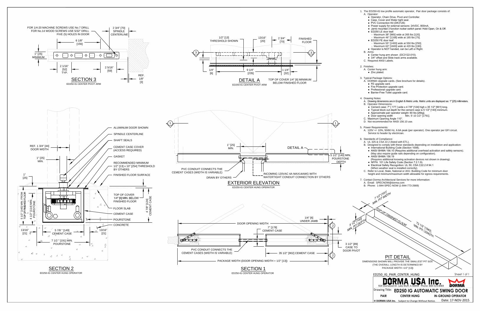
1. The ED250-IG low profile automatic operator, Pair door package consists of:
A. Operator:
● Operator, Chain Drive, Pivot and Controller.
● Case, Cover and Water tight seal.
● PVC Connection Kit (DK3126)
● Power supply for external sensors: 24VDC, 800mA.
●
● ED250 LE door leaf:
- Maximum 38" [965] wide at 265 lbs [120].
- Maximum 46" [1168] wide at 165 lbs [75].
● ED250 FE door leaf:
- Maximum 55" [1400] wide at 550 lbs [250].
- Maximum 63" [1600] wide at 420 lbs [190].
● Operator is NOT handed, can be Left or Right.
B. Arms:
● 3/4" Offset arm shown (DC3123-010).
● Center hung and Slide track arms available.
C. Required ANSI Labels.
2. Finishes:
A. 3/4" Offset arm:
● Dark Bronze painted.
● Silver painted.
3. Typical Package Options:
A. DORMA Upgrade cards. (See brochure for details).
● FE upgrade card.
● Fire Protection upgrade card.
● Professional upgrade card.
● Barrier-Free Toilet upgrade card.
4. Drawing Notes:
A.
B. Operator Dimensions:
● Cement case: 7" [ 177 ] wide x 4 7/8" [124] high x 35 1/2" [901] long.
● Typical block out depth for the cement case is 5 1/2" [140] minimum.
● Approximate pair operator weight: 60 lbs [26kg].
● Door opening width Min. 5'-6 5/8" [1692].
C. Maximum Opening Angle 110°.
D. Not recommended for ANSI 156.10 use.
5. Power Requirements:
A. 120V +/- 10%, 50/60 Hz, 6.6A peak (per operator). One operator per GFI circuit.
Service to header by electrician.
6. Standards of Compliance:
A. UL 325 & CSA 22.2 (listed with ETL).
B. Designed to comply with these standards depending on installation and application:
● International Building Code (Section 1008).
● ANSI/ BHMA 156.10 (Requires additional overhead activation and safety sensors).
(May also require guide rails depending on configuration).
● ANSI/ BHMA 156.19
(Requires additional knowing activation devices not shown in drawing).
● NFPA 101 Life Safety Code (Section 7.2.1.9).
● Electrical Safety Recognition: UL 50, CSA C22.2 # 94.1
(When weather seal is installed correctly).
C. Refer to Local, State, National or AHJ. Building Code for minimum door
height and minimum/maximum width allowable for egress requirements.
7. Contact Dorma Architectural Services for more information:
A. Email: [email protected]
B. Phone: 1-844-SPEC-NOW (1-844-773-2669)
PIT DETAIL
DIMENSIONS SHOWN WILL PROVIDE THE SMALLEST PIT SIZE
(THE OVERALL LENGTH IS DETERMINED BY
PACKAGE WIDTH +1/2" [13])

Drawing Title:
© DORMA USA Inc. Subject to Change Without Notice. Date: 17-NOV-2015
924 Sherwood Dr. Lake Bluff, IL 60044 Phone: 800-523-8483
ED250_IG_PAIR_SLIDE_TRACK_RABBET_PULL
SHAFT SEALS
GASKET
RECOMMENDED MINIMUM
1/2" [13] x 10" [254] THRESHOLD
BY OTHERS
FINISHED FLOOR SURFACE
PACKAGE WIDTH (DOOR OPENING WIDTH + 8 1/2" [216])
CEMENT CASE COVER
(ACCESS REQUIRED)
REF. 1 3/4" [44]
DOOR WIDTH
TOP OF COVER
FINISHED FLOOR
POURSTONE
CEMENT CASE
FLOOR SURFACE
35 1/2" [902] CEMENT CASE
2
2
11
DETAIL A
1 5/16" [32]
MIN.
SLIDE TRACK
CONCRETE
EXTERIOR ELEVATION
ED250-IG SLIDE TRACK OPERATOR
SECTION 1
ED250-IG SLIDE TRACK OPERATOR
SECTION 2
ED250-IG SLIDE TRACK OPERATOR
DOOR PIVOT HINGE
7" [178]
CEMENT CASE
4 1/4" [108]
UNDER JAMB
SPINDLE CENTERLINE
33
TOP OF COVER 1/4" [6] MINIMUM
BELOW FINISHED FLOOR
1 1/2" [39]
TRACK DEPTH
3/4" [19] RELIEF CUT
FOR ARM CLEARANCE
FINISHED
FLOOR
14" [356] RELIEF CUT FOR ARM CLEARANCE
11 13/16"
[300]
1"
[25]
1"
[25]
1 3/16"
[30]
1"
[25]
14" [356] RELIEF CUT FOR ARM CLEARANCE
3 15/16"
[100]
FOR 1/4-20 MACHINE SCREWS USE No.7 DRILL
FOR No.14 WOOD SCREWS USE 5/32" DRILL
TWO (2) HOLES IN DOOR
1 5/16" [33]
MINIMUM
1/4"
[6]
ALUMINUM DOOR SHOWN
DOOR PIVOT HINGE
SLIDE TRACK ARM
DETAIL A
ED250-IG SLIDE TRACK
SECTION 3
ED250-IG SLIDE TRACK
4 3/8" [111]
CASE TO
DOOR FACE
1/2" [13]
THRESHOLD SHOWN
PVC CONDUIT CONNECTS THE
CEMENT CASES (WIDTH IS VARIABLE)
PVC CONDUIT CONNECTS THE
CEMENT CASES (WIDTH IS VARIABLE)
DRAIN BY OTHERS
INCOMING 120VAC 4A MAX14AWG WITH
WATERTIGHT CONDUIT CONNECTION BY OTHERS
DOOR OPENING WIDTH
1" [25]
MIN.
5 1/2" [140] MIN.
POURSTONE
DEPTH
4 7/8" [124]
CE
ME
NT
C
AS
E
1"
[25]
5 1/2" [140] M
IN
. F
RO
M
4 1/2" [114] M
IN
.
PO
UR
ST
ON
E
5 7/8 " [149]
CEMENT CASE
13/16"
[21]
7 1/2 " [191] MIN.
POURSTONE
13/16"
[21]
1. The ED250-IG low profile automatic operator, Pair door package consists of:
A. Operator:
● Operator, Chain Drive, Pivot and Controller.
● Case, Cover and Water tight seal.
● PVC Connection Kit (DK3126)
● Power supply for external sensors: 24VDC, 800mA.
●
● ED250 LE door leaf:
- Maximum 38" [965] wide at 265 lbs [120].
- Maximum 46" [1168] wide at 165 lbs [75].
● ED250 FE door leaf:
- Maximum 55" [1400] wide at 550 lbs [250].
- Maximum 63" [1600] wide at 420 lbs [190].
● Operator is NOT handed, can be Left or Right.
B. Arms:
● Slide track shown (DK3424-010).
● Center hung and 3/4" offset arms available.
C. Required ANSI Labels.
2. Finishes:
A. Slide track:
● Dark Bronze painted.
● Silver painted.
3. Typical Package Options:
A. DORMA Upgrade cards. (See brochure for details).
● FE upgrade card.
● Fire Protection upgrade card.
● Professional upgrade card.
● Barrier-Free Toilet upgrade card.
4. Drawing Notes:
A.
B. Operator Dimensions:
● Cement case: 7" [ 177 ] wide x 4 7/8" [124] high x 35 1/2" [901] long.
● Typical block out depth for the cement case is 5 1/2" [140] minimum.
● Approximate pair operator weight: 60 lbs [26kg].
● Door opening width Min. 5'-3 1/2" [1613].
C. Maximum Opening Angle 110°.
D. Not recommended for ANSI 156.10 use.
5. Power Requirements:
A. 120V +/- 10%, 50/60 Hz, 6.6A peak (per operator). One operator per GFI circuit.
Service to header by electrician.
6. Standards of Compliance:
A. UL 325 & CSA 22.2 (listed with ETL).
B. Designed to comply with these standards depending on installation and application:
● International Building Code (Section 1008).
● ANSI/ BHMA 156.10 (Requires additional overhead activation and safety sensors).
(May also require guide rails depending on configuration).
● ANSI/ BHMA 156.19
(Requires additional knowing activation devices not shown in drawing).
● NFPA 101 Life Safety Code (Section 7.2.1.9).
● Electrical Safety Recognition: UL 50, CSA C22.2 # 94.1
(When weather seal is installed correctly).
C. Refer to Local, State, National or AHJ. Building Code for minimum door
height and minimum/maximum width allowable for egress requirements.
7. Contact Dorma Architectural Services for more information:
A. Email: [email protected]
B. Phone: 1-844-SPEC-NOW (1-844-773-2669)
PIT DETAIL
DIMENSIONS SHOWN WILL PROVIDE THE SMALLEST PIT SIZE
(THE OVERALL LENGTH IS DETERMINED BY
PACKAGE WIDTH +1/2" [13])
Drawing Title:
© DORMA USA Inc. Subject to Change Without Notice. Date: 17-NOV-2015
924 Sherwood Dr. Lake Bluff, IL 60044 Phone: 800-523-8483
ED250_IG_SINGLE_CENTER_HUNG
SHAFT SEALS
GASKET
RECOMMENDED MINIMUM
1/2" [13] x 10" [254] THRESHOLD
BY OTHERS
FINISHED FLOOR SURFACE
PACKAGE WIDTH
(DOOR OPENING WIDTH + 1/4" [6])
CEMENT CASE COVER
(ACCESS REQUIRED)
REF. 1 3/4" [44]
DOOR WIDTH
TOP OF COVER
FINISHED FLOOR
POURSTONE
CEMENT CASE
FLOOR SLAB
35 1/2" [902] CEMENT CASE
2
2
11
DETAIL A
1" [25]
MIN.
CONCRETE
EXTERIOR ELEVATION
ED250-IG CENTER HUNG OPERATOR
RIGHT HAND DOOR SHOWN
MIRROR FOR LEFT HAND
SECTION 1
ED250-IG CENTER HUNG OPERATOR
RIGHT HAND DOOR SHOWN
MIRROR FOR LEFT HAND DOOR
SECTION 2
ED250-IG CENTER HUNG OPERATOR
7" [178]
CEMENT CASE
1/4" [6]
UNDER JAMB
SPINDLE CENTERLINE
TOP OF COVER 1/4" [6] MINIMUM
BELOW FINISHED FLOOR
FINISHED
FLOOR
FOR 1/4-20 MACHINE SCREWS USE No.7 DRILL
FOR No.14 WOOD SCREWS USE 5/32" DRILL
FIVE (5) HOLES IN DOOR
ALUMINUM DOOR SHOWN
DETAIL A
ED250-IG CENTER PIVOT ARM
SECTION 3
ED250-IG CENTER PIVOT ARM
3 1/2" [89]
CASE TO
DOOR PIVOT
33
2 3/4" [70]
SPINDLE
CENTERLINE
2 3/4"
[70]
1 1/4"
[32]
2 5/16"
[59]
2 1/16"
[52]
TYP.
6 1/8"
[156]
9 1/4"
[235]
13/16"
[20]
1/4"
[6]
1" [25]
MINIMUM
REF.
1/8"
[3]
1/2" [13]
THRESHOLD SHOWN
DOOR OPENING WIDTH
36" MIN. POURSTONE LENGTH
INCOMING 120VAC 4A MAX14AWG
WITH WATERTIGHT CONDUIT
CONNECTION BY OTHERS
DRAIN BY OTHERS
5 1/2" [140] MIN.
POURSTONE
DEPTH
4 7/8" [124]
CE
ME
NT
C
AS
E
1"
[25]
5 1/2" [140] M
IN
. F
RO
M
4 1/2" [114] M
IN
.
PO
UR
ST
ON
E
5 7/8 " [149]
CEMENT CASE
13/16"
[21]
7 1/2 " [191] MIN.
POURSTONE
13/16"
[21]
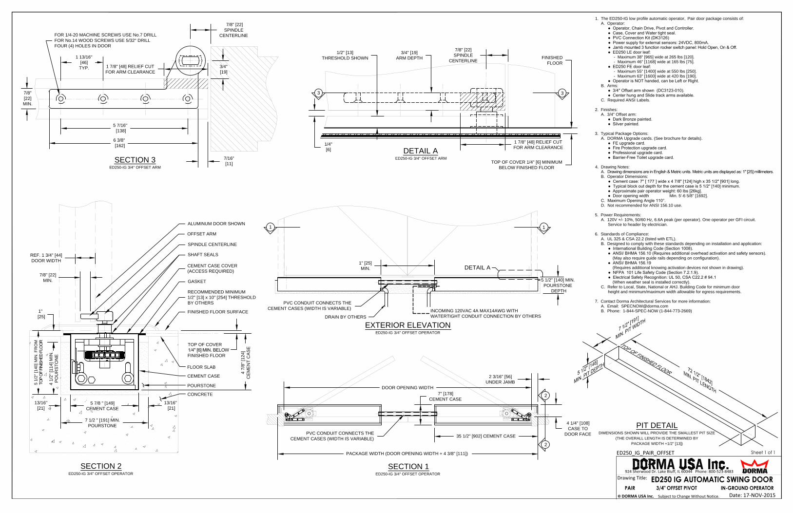
1. The ED250-IG low profile automatic operator, Single door package consists of:
A. Operator:
● Operator, Chain Drive, Pivot and Controller.
● Case, Cover and Water tight seal.
● Power supply for external sensors: 24VDC, 800mA.
●
● ED250 LE door leaf:
- Maximum 38" [965] wide at 265 lbs [120].
- Maximum 46" [1168] wide at 165 lbs [75].
● ED250 FE door leaf:
- Maximum 55" [1400] wide at 550 lbs [250].
- Maximum 63" [1600] wide at 420 lbs [190].
● Operator is NOT handed, can be Left or Right.
B. Arms:
● Center hung arm shown (DC3122-010).
● 3/4" offset and Slide track arms available.
C. Required ANSI Labels.
2. Finishes:
A. Center hung arm:
● Zinc plated.
3. Typical Package Options:
A. DORMA Upgrade cards. (See brochure for details).
● FE upgrade card.
● Fire Protection upgrade card.
● Professional upgrade card.
● Barrier-Free Toilet upgrade card.
4. Drawing Notes:
A.
B. Operator Dimensions:
● Cement case: 7" [ 177 ] wide x 4 7/8" [124] high x 35 1/2" [901] long.
● Typical block out depth for the cement case is 5 1/2" [140] minimum.
● Approximate single operator weight: 30 lbs [13 kg].
C. Maximum Opening Angle 110°.
D. Not recommended for ANSI 156.10 use.
5. Power Requirements:
A. 120V +/- 10%, 50/60 Hz, 6.6A peak (per operator). One operator per GFI circuit.
Service to header by electrician.
6. Standards of Compliance:
A. UL 325 & CSA 22.2 (listed with ETL).
B. Designed to comply with these standards depending on installation and application:
● International Building Code (Section 1008).
● ANSI/ BHMA 156.10 (Requires additional overhead activation and safety sensors).
(May also require guide rails depending on configuration).
● ANSI/ BHMA 156.19
(Requires additional knowing activation devices not shown in drawing).
● NFPA 101 Life Safety Code (Section 7.2.1.9).
● Electrical Safety Recognition: UL 50, CSA C22.2 # 94.1
(When weather seal is installed correctly).
C. Refer to Local, State, National or AHJ. Building Code for minimum door
height and minimum/maximum width allowable for egress requirements.
7. Contact Dorma Architectural Services for more information:
A. Email: [email protected]
B. Phone: 1-844-SPEC-NOW (1-844-773-2669)
PIT DETAIL
DIMENSIONS SHOWN WILL PROVIDE THE SMALLEST PIT SIZE

Drawing Title:
© DORMA USA Inc. Subject to Change Without Notice. Date: 17-NOV-2015
924 Sherwood Dr. Lake Bluff, IL 60044 Phone: 800-523-8483
ED250_IG_SINGLE_OFFSET
SHAFT SEALS
GASKET
RECOMMENDED MINIMUM
1/2" [13] x 10" [254] THRESHOLD
BY OTHERS
FINISHED FLOOR SURFACE
CEMENT CASE COVER
(ACCESS REQUIRED)
REF. 1 3/4" [44]
DOOR WIDTH
TOP OF COVER
FINISHED FLOOR
POURSTONE
CEMENT CASE
FLOOR SLAB
7/8" [22]
MIN.
CONCRETE
SECTION 2
ED250-IG 3/4" OFFSET OPERATOR
SPINDLE CENTERLINE
TOP OF COVER 1/4" [6] MINIMUM
BELOW FINISHED FLOOR
FINISHED
FLOOR
FOR 1/4-20 MACHINE SCREWS USE No.7 DRILL
FOR No.14 WOOD SCREWS USE 5/32" DRILL
FOUR (4) HOLES IN DOOR
OFFSET ARM
DETAIL A
ED250-IG 3/4" OFFSET ARM
SECTION 3
ED250-IG 3/4" OFFSET ARM
33
7/8" [22]
SPINDLE
CENTERLINE
3/4"
[19]
7/16"
[11]
1/4"
[6]
5 7/16"
[138]
1 13/16"
[46]
TYP.
1 7/8" [48] RELIEF CUT
FOR ARM CLEARANCE
6 3/8"
[162]
7/8" [22]
SPINDLE
CENTERLINE
3/4" [19]
ARM DEPTH
1 7/8" [48] RELIEF CUT
FOR ARM CLEARANCE
ALUMINUM DOOR SHOWN
7/8"
[22]
MIN.
PACKAGE WIDTH
(DOOR OPENING WIDTH + 2 3/16" [56])
35 1/2" [902] CEMENT CASE
2
2
11
DETAIL A
EXTERIOR ELEVATION
ED250-IG 3/4" OFFSET OPERATOR
RIGHT HAND DOOR SHOWN
MIRROR FOR LEFT HAND DOOR
SECTION 1
ED250-IG 3/4" OFFSET OPERATOR
RIGHT HAND DOOR SHOWN
MIRROR FOR LEFT HAND DOOR
7" [178]
CEMENT CASE
2 3/16" [56]
UNDER JAMB
4 1/4" [108]
CASE TO
DOOR FACE
1/2" [13]
THRESHOLD SHOWN
DOOR OPENING WIDTH
36" [914] MIN. POURSTONE LENGTH
INCOMING 120VAC 4A MAX14AWG
WITH WATERTIGHT CONDUIT
CONNECTION BY OTHERS
DRAIN BY OTHERS
5 1/2" [140] MIN.
POURSTONE
DEPTH
4 7/8" [124]
CE
ME
NT
C
AS
E
1"
[25]
5 1/2" [140] M
IN
. F
RO
M
4 1/2" [114] M
IN
.
PO
UR
ST
ON
E
5 7/8 " [149]
CEMENT CASE
13/16"
[21]
7 1/2 " [191] MIN.
POURSTONE
13/16"
[21]
1. The ED250-IG low profile automatic operator, Single door package consists of:
A. Operator:
● Operator, Chain Drive, Pivot and Controller.
● Case, Cover and Water tight seal.
● Power supply for external sensors: 24VDC, 800mA.
●
● ED250 LE door leaf:
- Maximum 38" [965] wide at 265 lbs [120].
- Maximum 46" [1168] wide at 165 lbs [75].
● ED250 FE door leaf:
- Maximum 55" [1400] wide at 550 lbs [250].
- Maximum 63" [1600] wide at 420 lbs [190].
● Operator is NOT handed, can be Left or Right.
B. Arms:
● 3/4" Offset arm shown (DC3123-010).
● Center hung and Slide track arms available.
C. Required ANSI Labels.
2. Finishes:
A. 3/4" Offset arm:
● Dark Bronze painted.
● Silver painted.
3. Typical Package Options:
A. DORMA Upgrade cards. (See brochure for details).
● FE upgrade card.
● Fire Protection upgrade card.
● Professional upgrade card.
● Barrier-Free Toilet upgrade card.
4. Drawing Notes:
A.
B. Operator Dimensions:
● Cement case: 7" [ 177 ] wide x 4 7/8" [124] high x 35 1/2" [901] long.
● Typical block out depth for the cement case is 5 1/2" [140] minimum.
● Approximate single operator weight: 30 lbs [13 kg].
C. Maximum Opening Angle 110°.
D. Not recommended for ANSI 156.10 use.
5. Power Requirements:
A. 120V +/- 10%, 50/60 Hz, 6.6A peak (per operator). One operator per GFI circuit.
Service to header by electrician.
6. Standards of Compliance:
A. UL 325 & CSA 22.2 (listed with ETL).
B. Designed to comply with these standards depending on installation and application:
● International Building Code (Section 1008).
● ANSI/ BHMA 156.10 (Requires additional overhead activation and safety sensors).
(May also require guide rails depending on configuration).
● ANSI/ BHMA 156.19
(Requires additional knowing activation devices not shown in drawing).
● NFPA 101 Life Safety Code (Section 7.2.1.9).
● Electrical Safety Recognition: UL 50, CSA C22.2 # 94.1
(When weather seal is installed correctly).
C. Refer to Local, State, National or AHJ. Building Code for minimum door
height and minimum/maximum width allowable for egress requirements.
7. Contact Dorma Architectural Services for more information:
A. Email: [email protected]
B. Phone: 1-844-SPEC-NOW (1-844-773-2669)
PIT DETAIL
DIMENSIONS SHOWN WILL PROVIDE THE SMALLEST PIT SIZE

Drawing Title:
© DORMA USA Inc. Subject to Change Without Notice. Date: 17-NOV-2015
924 Sherwood Dr. Lake Bluff, IL 60044 Phone: 800-523-8483
ED250_IG_SINGLE_SLIDE_TRACK_RABBET_PULL
SHAFT SEALS
GASKET
RECOMMENDED MINIMUM
1/2" [13] x 10" [254] THRESHOLD
BY OTHERS
FINISHED FLOOR SURFACE
PACKAGE WIDTH (DOOR OPENING WIDTH + 4 1/4" [108])
CEMENT CASE COVER
(ACCESS REQUIRED)
REF. 1 3/4" [44]
DOOR WIDTH
TOP OF COVER
FINISHED FLOOR
POURSTONE
CEMENT CASE
FLOOR SURFACE
35 1/2" [902] CEMENT CASE
2
2
11
DETAIL A
1 5/16" [32]
MIN.
SLIDE TRACK
CONCRETE
EXTERIOR ELEVATION
ED250-IG SLIDE TRACK OPERATOR
RIGHT HAND DOOR SHOWN
MIRROR FOR LEFT HAND DOOR
SECTION 1
ED250-IG SLIDE TRACK OPERATOR
RIGHT HAND DOOR SHOWN
MIRROR FOR LEFT HAND DOOR
SECTION 2
ED250-IG SLIDE TRACK OPERATOR
DOOR PIVOT HINGE
7" [178]
CEMENT CASE
4 1/4" [108]
UNDER JAMB
SPINDLE CENTERLINE
33
TOP OF COVER 1/4" [6] MINIMUM
BELOW FINISHED FLOOR
1 1/2" [39]
TRACK DEPTH
3/4" [19] RELIEF CUT
FOR ARM CLEARANCE
FINISHED
FLOOR
14" [356] RELIEF CUT FOR ARM CLEARANCE
11 13/16"
[300]
1"
[25]
1"
[25]
1 3/16"
[30]
1"
[25]
14" [356] RELIEF CUT FOR ARM CLEARANCE
3 15/16"
[100]
FOR 1/4-20 MACHINE SCREWS USE No.7 DRILL
FOR No.14 WOOD SCREWS USE 5/32" DRILL
TWO (2) HOLES IN DOOR
1 5/16" [33]
MINIMUM
1/4"
[6]
ALUMINUM DOOR SHOWN
DOOR PIVOT HINGE
SLIDE TRACK ARM
DETAIL A
ED250-IG SLIDE TRACK
SECTION 3
ED250-IG SLIDE TRACK
1/2" [13]
THRESHOLD SHOWN
INCOMING 120VAC 4A MAX14AWG
WITH WATERTIGHT CONDUIT
CONNECTION BY OTHERS
DRAIN BY OTHERS
PIT DETAIL
DIMENSIONS SHOWN WILL PROVIDE THE SMALLEST PIT SIZE
4 3/8" [111]
CASE TO
DOOR FACE
DOOR OPENING WIDTH
36" [914] MIN. POURSTONE LENGTH
5 1/2" [140] MIN.
POURSTONE
DEPTH
4 7/8" [124]
CE
ME
NT
C
AS
E
1"
[25]
5 1/2" [140] M
IN
. F
RO
M
4 1/2" [114] M
IN
.
PO
UR
ST
ON
E
5 7/8 " [149]
CEMENT CASE
13/16"
[21]
7 1/2 " [191] MIN.
POURSTONE
13/16"
[21]
1. The ED250-IG low profile automatic operator, Single door package consists of:
A. Operator:
● Operator, Chain Drive, Pivot and Controller.
● Case, Cover and Water tight seal.
● Power supply for external sensors: 24VDC, 800mA.
●
● ED250 LE door leaf:
- Maximum 38" [965] wide at 265 lbs [120].
- Maximum 46" [1168] wide at 165 lbs [75].
● ED250 FE door leaf:
- Maximum 55" [1400] wide at 550 lbs [250].
- Maximum 63" [1600] wide at 420 lbs [190].
● Operator is NOT handed, can be Left or Right.
B. Arms:
● Slide track shown (DK3424-010).
● Center hung and 3/4" offset arms available.
C. Required ANSI Labels.
2. Finishes:
A. Slide track:
● Dark Bronze painted.
● Silver painted.
3. Typical Package Options:
A. DORMA Upgrade cards. (See brochure for details).
● FE upgrade card.
● Fire Protection upgrade card.
● Professional upgrade card.
● Barrier-Free Toilet upgrade card.
4. Drawing Notes:
A.
B. Operator Dimensions:
● Cement case: 7" [ 177 ] wide x 4 7/8" [124] high x 35 1/2" [901] long.
● Typical block out depth for the cement case is 5 1/2" [140] minimum.
● Approximate single operator weight: 30 lbs [13 kg].
C. Maximum Opening Angle 110°.
D. Not recommended for ANSI 156.10 use.
5. Power Requirements:
A. 120V +/- 10%, 50/60 Hz, 6.6A peak (per operator). One operator per GFI circuit.
Service to header by electrician.
6. Standards of Compliance:
A. UL 325 & CSA 22.2 (listed with ETL).
B. Designed to comply with these standards depending on installation and application:
● International Building Code (Section 1008).
● ANSI/ BHMA 156.10 (Requires additional overhead activation and safety sensors).
(May also require guide rails depending on configuration).
● ANSI/ BHMA 156.19
(Requires additional knowing activation devices not shown in drawing).
● NFPA 101 Life Safety Code (Section 7.2.1.9).
● Electrical Safety Recognition: UL 50, CSA C22.2 # 94.1
(When weather seal is installed correctly).
C. Refer to Local, State, National or AHJ. Building Code for minimum door
height and minimum/maximum width allowable for egress requirements.
7. Contact Dorma Architectural Services for more information:
A. Email: [email protected]
B. Phone: 1-844-SPEC-NOW (1-844-773-2669)