Embed Size (px)
Citation preview
1
DET TEKNISK-NATURVITENSKAPELIGE FAKULTET
MASTEROPPGAVE
Studieprogram/spesialisering:
Petroleumsteknologi / Boreteknologi
Vår semesteret, 2012
Åpen
Forfatter: Tor Helge Haara Tjemsland …………………………………………
(signatur forfatter)
Fagansvarlig: Olav Gerhard Nygaard
Veileder: Olav Gerhard Nygaard
Tittel på masteroppgaven: Evaluation of Measurement-While-Drilling, telemetry methods and integration of control systems
Studiepoeng: 30
Emneord: Mud-Pulse Telemetry, Wired-Pipe
Telemetry, Downhole Tool Applications,
Procedures Applied During Downhole
Communication, Integrating the MWD/LWD
Service Into the Drilling Control System
Sidetall: 77
+ vedlegg/annet: 0
Stavanger, 15.06.2012 dato/år
2
1 Summary
This paper will present an overview of the applications of the measurements performed by
the Measurement-While-Drilling and Logging-While-Drilling tools. An evaluation of the available
telemetry techniques used to transfer the measured data from the downhole tools to surface are
performed, with special emphasis on Mud-Pulse Telemetry (MPT) and Wired-Pipe Telemetry (WPT).
MPT is by far the method most commonly used on the Norwegian Continental Shelf. WPT is a new
technology that allows a vast amount of data to be transferred, which could create new features for
the MWD/LWD service, and improve on others. The paper give an overview of the current
procedures applied during downhole communication with MPT, and explore the changes that could
be introduced by utilizing WPT. It is shown that WPT would allow several new applications of the
downhole measurements, without the same problems transferring data as MPT. WPT do not have
the same proven record of high reliability as MPT. Hence, MPT is probably going to remain the
preferred telemetry method in the future.
The paper explores the possibility to integrate the downhole measurements into a drilling
control system. It gives an example from Managed Pressure Drilling where this already has been
successfully utilized, and explore different other scenarios where an integration is possible. To fully
be able to exploit the downhole data, the amount of data received would need to be high. If utilized
in an automation system, the driller would need to fully understand how the system works, and be
given the means to override the automation system if necessary.

3
Contents 1 Summary.......................................................................................................................................... 2
Contents .................................................................................................................................................. 3
2 Introduction ..................................................................................................................................... 6
3 Downhole Tool Applications............................................................................................................ 8
3.1 Directional Drilling ................................................................................................................... 8
3.1.1 Requirements for directional drilling .............................................................................. 8
3.2 The MWD/LWD service ......................................................................................................... 11
3.2.1 Bi-Directional Communication ...................................................................................... 12
3.2.2 Power requirements ...................................................................................................... 13
4 Current Procedures Applied During Downhole Communication .................................................. 14
4.1 Normal operation – drilling/circulating ................................................................................. 14
4.1.1 Nuclear sources ............................................................................................................. 14
4.2 Survey .................................................................................................................................... 15
4.3 Downlink ................................................................................................................................ 16
4.4 Optimizing drilling parameters .............................................................................................. 16
4.5 Reservoir navigation .............................................................................................................. 17
4.6 Formation pressure point and fluid sampling ....................................................................... 17
4.7 Tripping operations and flow-off events ............................................................................... 18
4.8 Well control operations ......................................................................................................... 18
4.9 Lost circulation event ............................................................................................................ 19
4.10 Verification of MWD/LWD tool and shallow hole testing ..................................................... 19
4.11 Trouble shooting ................................................................................................................... 20
4.12 Data processing and distribution .......................................................................................... 20
5 Telemetry Techniques ................................................................................................................... 21
5.1 Mud Pulse Telemetry ............................................................................................................ 21
5.1.1 Surface Systems and Sensors ........................................................................................ 22
5.1.2 Signal transmitted ......................................................................................................... 24
5.1.3 Signal Property Description ........................................................................................... 26
5.1.4 Signal Attenuation ......................................................................................................... 30
5.1.5 Noise Sources ................................................................................................................ 32
5.1.6 Noise cancellation ......................................................................................................... 35
5.2 Wired-Pipe ............................................................................................................................. 38
5.2.1 Wired pipe transmission line. ........................................................................................ 39

4
5.2.2 Advantages of a wired-pipe Network ............................................................................ 41
5.2.3 Sensors in the signal repeaters...................................................................................... 48
5.2.4 Limitations of wired pipe technology ............................................................................ 49
5.2.5 Reliability ....................................................................................................................... 50
5.3 Additional MWD Transmitters .............................................................................................. 52
5.3.1 Electromagnetic ............................................................................................................. 52
5.3.2 Acoustic Transmission ................................................................................................... 53
6 Drilling Processes and Automation ............................................................................................... 55
6.1 Drilling processes ................................................................................................................... 56
6.1.1 Conventional Drilling ..................................................................................................... 56
6.1.2 Underbalanced Drilling .................................................................................................. 57
6.1.3 Managed Pressure Drilling ............................................................................................ 57
6.2 Automation............................................................................................................................ 58
6.2.1 Modes of automation .................................................................................................... 59
6.2.2 Envelope protection ...................................................................................................... 61
6.2.3 Sequential procedure .................................................................................................... 62
6.2.4 Closed-loop .................................................................................................................... 62
6.2.5 Challenges with automation.......................................................................................... 63
6.2.6 Control algorithms and models ..................................................................................... 63
7 Integrating the MWD/LWD Service Into the Drilling Control System ........................................... 65
7.1 Directional Drilling ................................................................................................................. 65
7.1.1 LWD tools used for reservoir navigation ....................................................................... 66
7.2 Optimizing drilling parameters .............................................................................................. 66
7.2.1 Vibrations ...................................................................................................................... 67
7.2.2 Drilling performance ...................................................................................................... 67
7.3 Monitoring annular pressure ................................................................................................ 67
7.3.1 Well control ................................................................................................................... 68
7.4 MWD measurements integrated into a MPD control system ............................................... 68
7.4.1 Optimizing the annular pressure ................................................................................... 69
7.5 Surface sensors ...................................................................................................................... 70
7.5.1 Radiation detector ......................................................................................................... 70
8 Discussion & Conclusion ................................................................................................................ 71
8.1 Telemetry methods ............................................................................................................... 71
8.1.1 Mud-pulse telemetry vs. Wired-pipe telemetry ........................................................... 71

5
8.2 Integration into a Drilling Control System ............................................................................. 73
8.3 Relations to health, safety and environment ........................................................................ 74
8.3.1 Downhole Annular and Formation Pressure Monitoring .............................................. 75
8.3.2 Reducing manual handling ............................................................................................ 75
9 Reference ...................................................................................................................................... 76
6
2 Introduction
MWD telemetry is required to link downhole and surface MWD components in real-time. The
system to support it is quite complex, with both downhole and surface components that operate
together. MWD telemetry is the process of transmitting information between downhole MWD tools
in the BHA to retrieval at surface. Uplinking is the process of transmitting information from downhole
to surface, and downlinking is the process of transmitting information and commands from surface
to downhole. Connectivity between downhole and surface is described as half-duplex; we can
transmit information in both directions, but not simultaneously. [1]
In 1964, a mud valve was suggested to transmit data up the mud-column, and in the 1970`s
transmission of data from tools contained within the bottom hole assembly (BHA) to surface was
achieved. [2] This system, called mud-pulse telemetry (MPT), utilized pressure pulses created in the
downhole tools for the transmission. Through the continuous column the drilling fluid, the pressure
pulses were detected on surface using a pressure transducer. This system was commercially
introduced by Teleco Oilfield Services Incorporated (now a part of Baker Hughes) in 1978. It
revolutionized the directional drilling industry by providing the directional driller with real-time
information for determination of the wellbore’s geometric position and steering system
performance.
Companies soon recognized the value of mud-pulse telemetry and developed formation
evaluation devices within the BHA. Transmission of this data to surface in real-time allowed the wells
trajectory to be referenced to geological features. Initially, natural gamma-ray and basic resistivity
devices were introduced and this soon expanded to an increasing range of sophisticated devices.
As the number of measuring devices in the BHA increases, so does the need for an increase in
data transmission from downhole to surface. To utilize the value of these measurements, MPT
technology continuously improves, and other telemetry technologies are developed. MPT is still the
most common, and compared to the alternative technologies, the MPT systems are characterized by
a proven record of high reliability in a wide range of operating environments.
Wired-pipe telemetry is a newly developed telemetry method which, compared to MPT,
ensures a vast amount of data is being received from the downhole components. The technology
could create new features for the MWD/LWD service, and improve on others.
Several oil service companies provide their own versions of the different MWD/LWD
measurement tools and the system used to transfer data to surface. The principle is the same in-
between the companies and this paper will therefore concentrate on the system utilized by Baker
Hughes. Historically, Baker Hughes has been one of the leading companies in the evolution of
downhole communication. Not only were they the first to commercially deliver Mud-Pulse
Telemetry, they were also the first company that developed the equipment which made it possible to
connect their downhole measuring tools to a networked wired-pipe system. The wired-pipe system
described in this paper is provided by NOV.
The drilling process still heavily depends on pure manual control. In principle, there is little
difference from the way the drilling process is controlled today and 50 years ago. [3]The process is

7
mainly controlled using surface data consisting of often limited number of parameters, some of
which are quite crude measurements derived from secondary data sources. Typically data consists of
surface WOB, pump flow rate and standpipe pressure, string rotation and surface torque. As the
development of automation systems are increasing, there could be a possibility of integrating
downhole measurements from the MWD/LWD tools into a Drilling Control System. The technology
has already been deployed, using downhole pressure measurements to help adjusting the annular
pressure in an MPD process.

8
3 Downhole Tool Applications
Many fields currently being drilled by the petroleum industry require the use of high angle,
extended reach wells to access remote hydrocarbon deposits. [4] Pre-drilled geomechanical
modeling efforts are routinely undertaken in fields where significant wellbore instabilities are known
to exist. However, it is not always possible to construct a robust pre-drill model due to a variety of
reasons (e.g., insufficient useful data). This combined with the fact that significant geological
uncertainties may still exist, could limit the effectiveness of pre-drill geomechanical models when
applied to a current drilling campaign.
LWD borehole images provide critical useful information in terms of borehole quality and
position within the reservoir. When used in real time, these images can help with making decisions
on drilling hazard migration and well placement during drilling. Recent advances in telemetry rates
show that higher resolution image quality, approaching or equaling that of memory data is now
available real-time. This technology has enabled the visualization of geomechanical features at
sufficient resolution to be useful for real-time decision-making applications.
3.1 Directional Drilling
Directional drilling is the intentional deviation of a wellbore from the path it would normally
take. [5, 6] It is the ability to plan and drill a wellbore along a predetermined trajectory to hit a sub-
surface target or targets. The target may be geometric or may be adjusted real-time based on
information learned about the formation while drilling. This is accomplished through the use of whip
stocks, bottomhole assembly (BHA) configurations, instruments to measure the path of the wellbore
in three-dimensional space, data links to communicate measurements taken downhole to the
surface, mud motors and special BHA components and drill bits, including rotary steerable systems
(RSS), and drill bits. The directional driller also exploits drilling parameters such as weight on bit and
rotary speed to deflect the bit away from the axis of the existing wellbore.
The advantages of directional drilling are that it allows access to reservoirs that cannot be
reached with a vertical well from above. Production and ultimate recovery is increased with a
horizontal well that exposes more of the reservoir. There is also a reduced cost and HSE impact by
having the possibility to drill multiple wells from one surface location. On an offshore location, like on
the Norwegian Continental Shelf, the ability to drill from the same surface location is a major
advantage.
3.1.1 Requirements for directional drilling
In both directional and vertical wells, the position of the well must be known with reasonable
accuracy to ensure the correct wellbore path and to know its position in the event a relief well must
be drilled. It is also critical in terms of a safety and economic value with regards to collision avoidance
with existing and planned wells. Thus, it is required to take surveys is every so often. The diagnostic
data from the downhole components, such as the steering parameters programmed in the tool, is
useful to be able to troubleshoot and prevent failures of the directional tools. The possibility to run
9
more advanced tools, which measure the downhole drilling parameters, is a service highly
appreciated by the directional driller to get a real-time picture of the drilling progress.
3.1.1.1 Survey
A survey is a complete measurement of the
inclination and azimuth of a location in a well, typically
the total depth at the time of the measurement. [5] The
measurements themselves include inclination from
vertical and the azimuth (or compass heading) of the
wellbore if the direction of the path is critical. These
measurements are made at discrete points in the well,
and the approximate path of the wellbore computed
from the discrete points. Measurement devices range
from simple pendulum-like devices to complex electronic
accelerometers and gyroscopes used more often as
MWD becomes more popular.
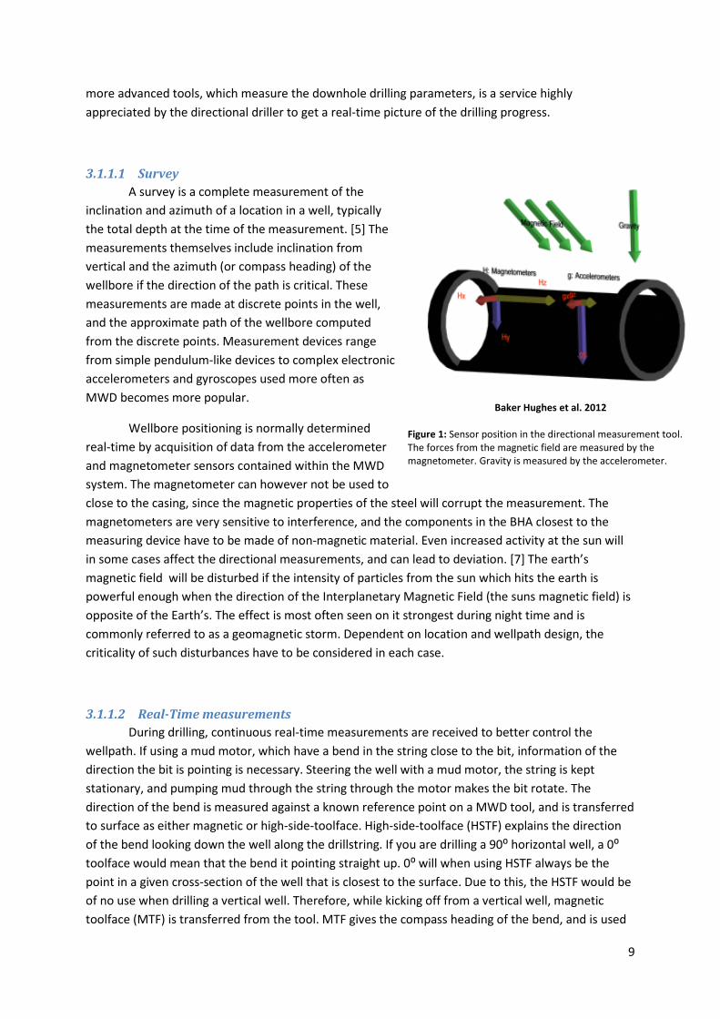
Wellbore positioning is normally determined
real-time by acquisition of data from the accelerometer
and magnetometer sensors contained within the MWD
system. The magnetometer can however not be used to
close to the casing, since the magnetic properties of the steel will corrupt the measurement. The
magnetometers are very sensitive to interference, and the components in the BHA closest to the
measuring device have to be made of non-magnetic material. Even increased activity at the sun will
in some cases affect the directional measurements, and can lead to deviation. [7] The earth’s
magnetic field will be disturbed if the intensity of particles from the sun which hits the earth is
powerful enough when the direction of the Interplanetary Magnetic Field (the suns magnetic field) is
opposite of the Earth’s. The effect is most often seen on it strongest during night time and is
commonly referred to as a geomagnetic storm. Dependent on location and wellpath design, the
criticality of such disturbances have to be considered in each case.
3.1.1.2 Real-Time measurements
During drilling, continuous real-time measurements are received to better control the
wellpath. If using a mud motor, which have a bend in the string close to the bit, information of the
direction the bit is pointing is necessary. Steering the well with a mud motor, the string is kept
stationary, and pumping mud through the string through the motor makes the bit rotate. The
direction of the bend is measured against a known reference point on a MWD tool, and is transferred
to surface as either magnetic or high-side-toolface. High-side-toolface (HSTF) explains the direction
of the bend looking down the well along the drillstring. If you are drilling a 90⁰ horizontal well, a 0⁰
toolface would mean that the bend it pointing straight up. 0⁰ will when using HSTF always be the
point in a given cross-section of the well that is closest to the surface. Due to this, the HSTF would be
of no use when drilling a vertical well. Therefore, while kicking off from a vertical well, magnetic
toolface (MTF) is transferred from the tool. MTF gives the compass heading of the bend, and is used
Baker Hughes et al. 2012
Figure 1: Sensor position in the directional measurement tool. The forces from the magnetic field are measured by the magnetometer. Gravity is measured by the accelerometer.
10
by the directional driller until the inclination of the well is large enough for HSTF to be reasonable to
use.
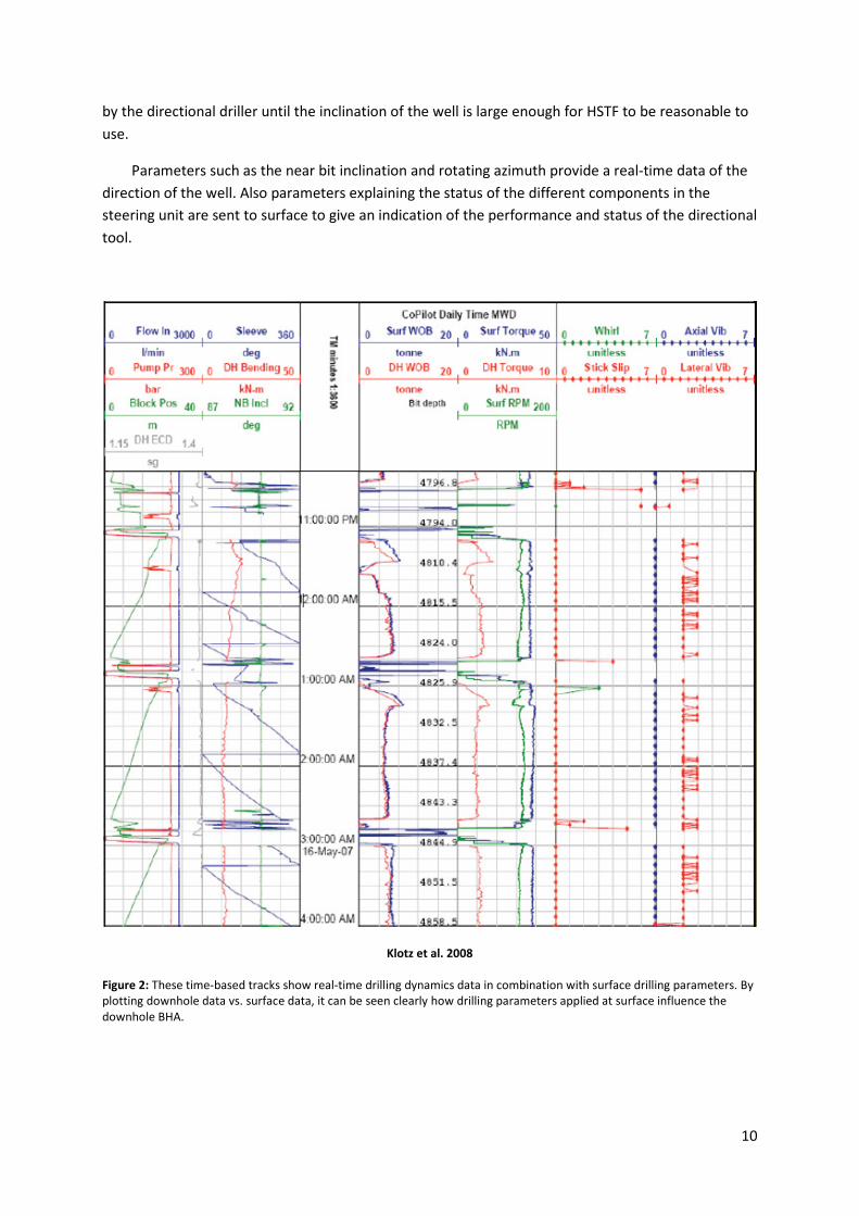
Parameters such as the near bit inclination and rotating azimuth provide a real-time data of the
direction of the well. Also parameters explaining the status of the different components in the
steering unit are sent to surface to give an indication of the performance and status of the directional
tool.
Klotz et al. 2008
Figure 2: These time-based tracks show real-time drilling dynamics data in combination with surface drilling parameters. By plotting downhole data vs. surface data, it can be seen clearly how drilling parameters applied at surface influence the downhole BHA.

11
Service companies can provide a service used for real-time drilling optimization where the forces
acting on the BHA are measured. Monitoring these values, transmitted as vibration and stick-slip,
give a picture of the downhole environment, and can be used to improve the drilling progress and
protect the downhole equipment. For example, Baker Hughes CoPilot service utilizes an advanced
downhole acquisition and processing sub that is incorporated into the BHA. This downhole sub
simultaneously samples 14 sensors such as:
• strain gauges (to measure downhole weight on bit, torque, bending moment and detect
whirl and bit bounce)
• accelerometers (to measure accelerations in 4 directions: axial, lateral-x, and lateral-y, and
tangential)
• magnetometer (to measure downhole rotational speed and detect whirl)
• annular and bore pressure
• Temperature (internal and external).
This raw data is processed downhole (scaled, temperature and pressure compensated), then
written to the tools memory and made available for transmission to surface, where it is interpreted
and used to optimize the drilling process.
Downhole drilling dynamics subs have been used for several years as a part of the common
BHA for drilling. The internal sampling rates of these tools are in the 100Hz range. However, only a
minor fraction of the data is transmitted to surface in real-time.
3.1.1.3 Downhole commands
While steering the well using RSS, it is necessary to have the possibility to make adjustments to
the steering parameters programmed into the tool. Depending on the system used, these commands
could be a force or direction needed to steer the well path along the planned trajectory, a desired
target inclination or to enable/disable the steering unit itself.
3.2 The MWD/LWD service
Measurement-While-Drilling (MWD) is the evaluation of physical properties, usually including
pressure, temperature and wellbore trajectory in three-dimensional space, while extending a
wellbore. [5] The measurements are made downhole, stored in solid-state memory for some time
and later transmitted to the surface. Most MWD tools have the ability to store the measurements for
later retrieval when the tool is tripped out of the hole, to provide higher resolution logs than it is
possible with the relatively low bandwidth mud-pulse data transmission system.
Logging-While-Drilling (LWD) is the measurement of geologic formation properties while using
tools incorporated into the drilling assembly. [6] A variety of services are available to evaluate the
zones being drilled through. Most importantly, LWD seeks to define reservoirs’; porosity,
permeability, pressure, producibility, hydrocarbon content and/or boundaries. It enables valuable,
real-time decisions on wellbore placement, determination of fluid properties before alteration by
drilling fluid invasion. It also assures log data acquisition in applications unsuitable for wireline.

12
Klotz et al. 2008
Figure 3: Example of an advanced MWD/LWD toolstring.
3.2.1 Bi-Directional Communication
There is a variety of different MWD/LWD tools measuring the physical properties downhole
and the geological formation properties of the drilled formation. The different service companies
have their own tools to perform these measurements, and send the information to surface.
Depending on the service, there could also be necessary to send commands and requests to
the MWD/LWD tools. This is known as a downlink. Adjustments to the data output and performance
of the tools can be changed from surface, often depending on the requirements from the client.
3.2.1.1 Formation pressure and fluid sampling tools
Service companies provide tools that give the downhole formation pressure and mobility
while drilling. [8] The newest generation of tools, also provides an opportunity to take samples of the
formation fluid. This is a service that previous only was provided by wireline. The values of the
pressure measurements can be seen in a variety of areas at the well site, such as reservoir
characterization, drilling efficiency, wellbore integrity and safety.
13
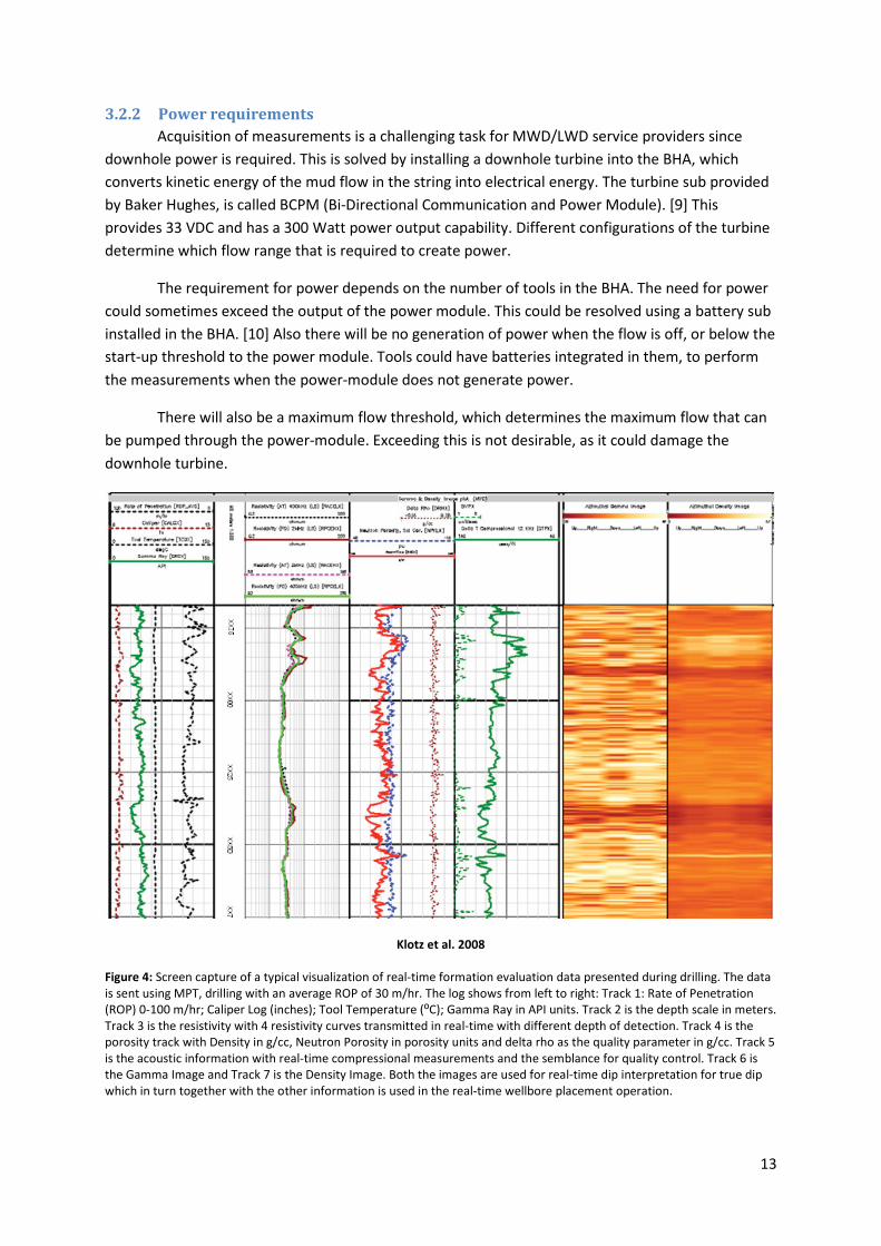
3.2.2 Power requirements
Acquisition of measurements is a challenging task for MWD/LWD service providers since
downhole power is required. This is solved by installing a downhole turbine into the BHA, which
converts kinetic energy of the mud flow in the string into electrical energy. The turbine sub provided
by Baker Hughes, is called BCPM (Bi-Directional Communication and Power Module). [9] This
provides 33 VDC and has a 300 Watt power output capability. Different configurations of the turbine
determine which flow range that is required to create power.
The requirement for power depends on the number of tools in the BHA. The need for power
could sometimes exceed the output of the power module. This could be resolved using a battery sub
installed in the BHA. [10] Also there will be no generation of power when the flow is off, or below the
start-up threshold to the power module. Tools could have batteries integrated in them, to perform
the measurements when the power-module does not generate power.
There will also be a maximum flow threshold, which determines the maximum flow that can
be pumped through the power-module. Exceeding this is not desirable, as it could damage the
downhole turbine.
Klotz et al. 2008
Figure 4: Screen capture of a typical visualization of real-time formation evaluation data presented during drilling. The data is sent using MPT, drilling with an average ROP of 30 m/hr. The log shows from left to right: Track 1: Rate of Penetration (ROP) 0-100 m/hr; Caliper Log (inches); Tool Temperature (⁰C); Gamma Ray in API units. Track 2 is the depth scale in meters. Track 3 is the resistivity with 4 resistivity curves transmitted in real-time with different depth of detection. Track 4 is the porosity track with Density in g/cc, Neutron Porosity in porosity units and delta rho as the quality parameter in g/cc. Track 5 is the acoustic information with real-time compressional measurements and the semblance for quality control. Track 6 is the Gamma Image and Track 7 is the Density Image. Both the images are used for real-time dip interpretation for true dip which in turn together with the other information is used in the real-time wellbore placement operation.

14
4 Current Procedures Applied During Downhole Communication
The vast majority of the wells being drilled on the Norwegian Continental Shelf are
conventional wells where the communications with the downhole tools are conducted with mud-
pulse telemetry. The following explanation of the existing procedures will therefore be under the
assumption that it is a conventional drilled well, where mud-pulse telemetry is used. A thorough
explanation of the MPT system follows in a later subchapter.
4.1 Normal operation – drilling/circulating
Prior to tripping in hole with the BHA, the MWD/LWD tools are being tested and programmed
on surface. The tools are then being programmed to send up the different data required by the
client. These requirements could be different from client to client, well to well, which sections being
drilled etc. A resemblance would be that the data required are larger the closer to the reservoir the
well gets. Hence, to be able to get good resolution data, the desired data-rate (the “speed” the data
is being transmitted with) from the client will also increase as the well gets deeper.
Drilling in the reservoir, especially when geosteering the well using the LWD logs, the data
resolution of the logs is important. However, getting the directional and vibration data for the
Directional Driller as well as the measurements of the physical properties in the wellbore will of
course be of equal importance. There are, in other word, a vast amount of data required to be able
to drill the well the best way. The limitations may therefore be the data-rate that the mud-pulser
managed to send the data to surface with. If that is the case, the solution would be limitations to the
rate of penetration (ROP), to increase the amount of data received from downhole per drilled meter.
Hence, more rig time could be spent drilling/logging than possible necessary. This would however
only increase the data density of the data that is dependent on the position in the well, such as the
LWD measurements of the formation. Time related data, such as pressure and strain, will be sent up
and stored with the same data density regardless of the ROP.
4.1.1 Nuclear sources
Some of the LWD tools have to use a nuclear source installed in them prior to running in hole.
These tools, which measure neutron porosity and gamma density, are very important while
geosteering the well, and are usually run in the sections close to the reservoir. To be able to use
nuclear sources for logging proposes, there is a lot of regulations that needs to be followed.
Continues measurements of the radiation are performed, to ensure that it is always known where
the source is. The MWD/LWD tools do not perform any of these measurements itself, but a LWD tool
that is working, continuously transmits reasonable data, is a good indication that the source is
installed in the tool. A stand-alone radiation detector is mounted on the flow-out line from the well,
and it will trigger an alarm in the MWD/LWD operators monitoring system if radiation is detected.
When the alarm is triggered, the operator has to notify the driller, who stops circulation. A manual
reading is then performed at the shakers to confirm the radiation measurements. If an incident like
15
this should occur, the goal would be to prevent as much radiation contamination of the rig as
possible.
4.2 Survey
During the drilling of a bore hole, one regularly measures the inclination, azimuth and
measured depth of the trajectory at a point near the drill bit. Such a measurement is required by the
Norwegian Petroleum Directorate (Ptil):
“During drilling operations the Licensee is required to know the well’s position at all times.
Measurements which determine inclination and azimuth shall be taken at intervals not exceeding 100
m, and they shall be commenced after the surface casing has been set, or at the depth that the
Norwegian Petroleum Directorate deems necessary”. [11]
These are minimum requirements, and when drilling deviational wells, more frequent
measurements may be taken to permit a more accurate determination of the wellbore trajectory.
The directional driller decides if a survey station can be skipped or not.
It is usual to perform a directional survey after each drilled stand. To get a good measurement,
the torque has to be worked out of the drill string, and the string has to be kept stationary. The MWD
tool is programmed to make a measurement if the tool is powered up without rotation. Hence, the
flow through the tool has to be reduced to the amount where the tool shuts off. When the flow then
is brought back up, the tools makes the necessary measurements and sends them to surface. The
time to take each survey will depend on the startup time of the mud-pulser in the tool, and the data-
rate used to transmit the measurements. When the data is received, and rotation of the string
commences, the MWD changes its data transfer to continue transmitting the measurements from
the MWD/LWD tools.
When the stand is drilled down, a connection is performed where a new stand is added to the
drillstring. During this process, there is no flow through the drillstring. For this reason, the survey
process is usually performed prior to commence drilling on the new stand. This way, the survey is
performed while establishing circulation again after the connection, which saves rig time.
This practice could vary dependent on the procedure on rig, and sometimes also be change
depending on the condition of the well. After every drilled stand the driller makes measurements of
the weight it requires to move the drillstring up and down in the well. Comparing these to the last
performed measurements and simulated values, give an indication whether or not the hole is in good
condition. Over-pull, when the up weight is larger than expected, could indicate poor hole-cleaning
or tight hole. In those cases it is not desired to stay stationary longer than necessary, especially not
on the top of a stand. If the drill string then gets stuck, it leaves little room for the driller to move the
pipe. Even though it will be more time consuming, surveys are in those cases usually performed prior
to picking up a new stand and performing a connection.
At surface, the survey is then verified prior to re-commencement of drilling operations. Most
drilling programs call for a survey to be recorded each drilled stand. Errors associated with survey
data has been modeled, allowing the uncertainty associated with the selected survey program to be
defined with a certain statistical probability. In cases where it is important to reduce the positional
16
uncertainty, more advanced surveying methods are employed. These include use of multiple sensors
within the BHA and/or use of more frequent survey data sets. It is not accounted for gross error in
the model; hence a quality control of survey data should be considered critical in all cases.
4.3 Downlink
During downlinks, adjustments to the flow in or RPM have to be performed for the downhole
tool to recognize the action it is required to do. During the time a downlink takes, data transfer from
downhole stops. The newest generation’s mud-pulsers are able to recognize the downlink and
continue transmitting data; however they still stop sending data at the end of the downlink to give a
confirmation that it was successful. This will of course affect the real-time logs, and continue drilling
while sending downlinks, could lead to poorer data resolution on the logs. To assure sufficient data
density, the procedure could therefore be a limitation on the ROP while sending these downlinks. In
some instances, it could also be required to stop drilling until the downlink has finished. The time
needed from the data transfer stops to the confirmation that the bottomhole tool understood the
downlink command is received, will vary, but can in some cases take several minutes. When
geosteering the well, adjustments to the wellpath will be decided from the real-time analysis of the
downhole LWD data. The consequence of this could be that it would be necessary to send a large
amount of downlinks during the drilling to adjust the parameters in the steering unit. Since it is
important with a good resolution LWD log during geosteering, it is usual to stop drilling while
downlinking the required drilling parameters. Hence, during this phase of the drilling, quite a lot of
time could be spent off-bottom downlinking.
Baker Hughes has developed a system to send downlinks without adjusting the pump output or
the string RPM. A module is connected on rig floor which diverts between 10-20% of the flow being
pumped down the string. This gives the same effect as adjusting the pump output, but is remote
controlled from by the MWD operator on the rig. Even though this affects the inflow in the well, this
is not a part of the rigs drilling equipment. Hence, approval from the driller needs to be given prior to
operating the downlink controller, as it affects the flow into the well and the stand pipe pressure.
4.4 Optimizing drilling parameters
With moderate data transmitting levels of LWD service using conventional MPT, it is typical to
transmit these data sets to surface every 45 to 60 seconds. These update rates are sufficient to
quantifiably enhance performance, but provide an incomplete snapshot view of downhole drilling
dynamics, especially when drilling with high ROP or when presented with telemetry decoding
difficulties.
Stick-slip is a torsional vibration mode which can result in very high angular accelerations and
peak values in rotary speed (including backwards rotation) at the BHA. These accelerations and peak
rotary speeds can damage the drill bit and BHA components resulting in premature failure. Stick-slip
also negatively impacts drilling performance by providing a less effective cutting action of the drill bit
to the formation. The most harmful vibrations can critically damage the BHA in a matter of a few
minutes (e.g. back whirl events). Hence, there can be insufficient time to react and prevent a failure
resulting from the damaged caused. The true severity and character of the dynamic event might not
17
become evident before from post well analysis is done of memory data. When the highest LWD
service levels are used it is sometimes even necessary to restrict or stop transmission to surface of
some dynamics sensor data to maximize bandwidth available for real-time formation evaluation data
transmission.
While milling casing, there could be a problem with pack-off events close to the bit. In these
cases, a CoPilot could be run to try to spot these events early. Also close monitoring of other
downhole parameters such as WOB and torque would be helpful to see that the surface force is
transmitted down to the bit, and that the BHA does not get hang-up in something above it. When
monitoring the bore- and annular pressure, changes in the measurements could indicate pack-off. In
these events an early warning is important, since the pressure buildup starts slowly, but increases
almost exponentially as it gets time to develop. This would eventually be seen clearly from the
surface parameters, such as the stand pipe pressure. Hence, this is a service where the amounts of
updates from the downhole parameters are important.
4.5 Reservoir navigation
Reservoir navigation can be described as pro-active geosteering using LWD measurements to
update geological models in real-time, and thereby refining the wellpath to stay in a defined
formation target. [2] The more complete the LWD measurement set is in real-time, the better the
chance for an accurate model update. A complete LWD data set for reservoir navigation could
include multiple propagation resistivity measurements, deep reading resistivity images, nuclear
porosity measurements and images, and gamma-ray measurements and images.
Reservoir navigation applications can also call for measurements that can help determine
optimal production zones and update reservoir model parameters in real-time. For instance, data
from a formation pressure test can be used to calculate pressure gradients and even determine
reservoir fluid mobility using a complete pressure transient analysis.
The interactive real-time usage of formation evaluation information while drilling long
horizontal wells has a direct influence on the productivity of the well. [12] Depending on the
reservoir geometry, depositional environment and post deposition tectonic movement, long
horizontals are likely to pass through several reservoir zones and often faulting. This consequence of
this could be that the reservoir being penetrated has large variations in quality. Faults are often of
sub seismic magnitude and can lead to an increased uncertainty in the interpretation. In faulted
reservoirs high LWD data density is often necessary to be able to ensure interpreting of images for
geological and structural evaluation with high confidence. This is particularly important in marginal
fields and if high precision steering is required to maintain the optimal well trajectory.
4.6 Formation pressure point and fluid sampling
LWD pressure testing tools can be used to make accurate formation pressure measurements
to adjust drilling fluid properties in real-time for avoiding kicks or fluid loss. [2] When a formation
pressure test is performed, the drill string has to be stationary and all torque worked out. [13] After
downlinking a command to the LWD tool to start a test, the tool deploys a test pad which seals to the

18
formation at the desired test depth, and the pressure test commence. During the test, the drillpipe
must be kept stationary. In the instance of a fluid sample being collected, the test itself may take
several hours. During the fluid sampling, continuous information is received regarding the
performance of the tool. However, during formation pressure testing, which also is the start
sequence of a fluid is sampling, no information is sent to surface prior to the test ending. Hence,
there is not possible to see if it is a good test before it is completed. LWD pressure tests are
performed “blindly”, with pre-programmed test parameters. The result of the test is transmitted to
surface for analysis, which even with data compression techniques can require a significant amount
of time. If the test parameters were not optimal, the test can be performed again with optimal
parameters by downlinking to the tool and reprogramming it. This is of course at the cost of
additional operation delays.
Prior to an operation where it is known that the string is going to be kept stationary for a while,
it is usually included into the drilling program to perform a sticky test. Even though there is
continuous circulation during the pressure test to keep the tools powered up, there is still a risk of
getting the drillsting differentially stuck. Hence, the time the drillstring is stationary should be kept to
a minimum.
4.7 Tripping operations and flow-off events
As mentioned earlier, it is not possible to communicate with the tool without having sufficient
circulation through the power-module. If a battery package is installed, the pressure data during the
tripping and flow-off events will be stored in the memory, but not be accessible on surface until the
memory from the tool is downloaded.
It would however be possible to get the maximum and minimum pressures from the period
without sufficient flow. These data would be sent up together with the survey data, and to retrieve
them the ordinary survey procedure has to be followed. The minimum pressure reading would, if
there is no flow, be the pressure of the above mud column, i.e. the hydrostatic pressure. Maximum
recorded pressure is used when performing LOT/FIT test. The reading from the downhole sensor will
then show the maximum pressure recorded downhole during the test, and is most often used to
confirm the surface data from the test.
4.8 Well control operations
Well control operations are the emergency procedures followed when formation fluids begin
to flow uncontrolled into the well, commonly known as a kick. The two widely accepted methods
adopted by the drilling industry are known as the “Drillers Method” or the “Wait and Weight”
method. In both methods it is necessary to maintain the bottomhole pressure continuously above
formation pore pressure to prevent further influx of formation fluid. It is normally considered ideal
that the bottomhole pressure is maintained just slightly above formation pressure to prevent
fracturing other stratum and creating the conditions for an underground blowout.
Most kill operations are conducted at flow-rates below which the MWD tools are able to
transmit mud-pulses; hence the downhole pressure gauges mounted in the BHA cannot be used. Due

19
to a battery package in MWD tool, the tool will perform pressure measurements during the kill
operations, but only the max and min pressure will be sent to surface when the tool starts pulsing
again.
4.9 Lost circulation event
Conventional MPT pulsars are vulnerable to blockage when Lost Circulation Material (LCM) is
pumped. This can cause loss of transmission or, in the very worst case, complete blockage of the drill
string preventing further drilling fluid circulation. This can be highly inconvenient as it normally
requires a trip out of hole to replace the blocked MPT system. In a situation where LCM is being
circulated this can also be hazardous as a well control incident is either potentially imminent or
occurring.
4.10 Verification of MWD/LWD tool and shallow hole testing
It is common practice to shallow test the BHA when running in hole as a final check of
functionality before reaching bottom. Decoding MPT signals during a shallow test can be difficult as
the mud is cold and un-sheared. This can cause uncertainty in the shallow hole test if full decode is
not achieved. Additionally, with a Rotary Steering System (RSS) in hole, it could also be required to
check that the downlink communication functions correctly.
The BHA`s usually have a float sub installed in them, which only allows flow down the string.
Hence, when tripping in hole, the string will not contain mud. Due to the buoyancy, the common
procedure is to fill the string and break circulation every 1000 meters. It is during one these events
the shallow test is performed. Preferably it is performed as early in the tripping process as possible. If
the MWD string does not respond as expected, a trip out of hole is required to change MWD
components. However, a verification of the complete MWD string is always done in the derrick prior
to running in hole. The majority of times, faults with the MWD tools are discovered then. Hence,
some oil companies do not want to spend rig time on performing a shallow-hole test. The cumulative
time spent on the tests would exceed the time it takes to do a complete trip out of hole in those rare
events of a faulty MWD string.
Prior to start drilling in a well where the mud has been stationary for a while, it is usual to
choose a slow data-rate. As circulation of the mud commences, the mud parameters will change, for
instance induced by the temperature changes. When proper downhole communication is
established, it could be required to downlink to a faster data-rate.
Pulling out of hole, the same verification of the MWD string is done in the derrick, as when
tripping in. Most importantly this is to verify the resistivity readings when the tool is hanging in air.
Laying them in a steel basket, would make it impossible to compare the post- and pre-run
verifications. While connected to verify the tool, it is usual to download the memory data from them
as well, to quickly be able to provide the customer with the complete formation evaluation memory
logs.

20
4.11 Trouble shooting
In case of a failure on the tools, a diagnostic downlink could be sent, which request a set of
parameters from the tools with information not given during normal operation. This could for
instance include current and voltage output/input to the different components. Receiving this
information and comparing it to the known reference values, could be helpful in the troubleshooting
process, and might helping preventing a costly trip out of hole.
Prior to tripping out of hole, the wellbore must be circulated clean from the generated
cuttings. Depending on the length of the well, it could take some hours before the state of the well is
satisfactory. The troubleshooting will take place during this time, as well as the decision if to
continue drilling without the faulty part. A part of the troubleshooting would be to lower the flow
below the power-up threshold of the tool for different periods of time. It has been experienced that
the faulty part could start functioning again if the toolstring has been without power for some time.
4.12 Data processing and distribution
When the measured downhole drilling parameters and formation evaluation data are received
at surface, it gets processed and stored in a database which is periodically replicated from the
wellsite to a secure data center. [10] It is also sent from the MWD/LWD service company’s surface
software system to the client’s computer system via WITSML.
The WITSML software format a data stream through a firewall and into the client’s IT
environment for applications by the operator in proprietary or third party software’s. The received
and processed data can then be displayed instantly on the rig, in field headquarters, and in off-site
collaboration centers.

21
5 Telemetry Techniques
In telemetry systems, a telemetry channel carries information. There are several telemetry
channels that can carry a signal, and these can be grouped into two classes; those that require no
change to the drillstring, and those that require either a modification to the drillstring or a radical
change in drilling practices. We can further classify the transmission methods based on how far they
can transmit information, and their channel capacity. The channel capacity is usually expressed in
bits per second. When classifying in this manner, it will range from conventional methods which use
existing channels and which are limited in capacity, to those that are unconventional and use
additional channels, but which can handle a greater flow of information.
From a technical standpoint, the ideal MWD telemetry system is one that has a great reach
and high potential data rate.
Examples of transmission methods that transmit information in the telemetry channels
include mud pulse telemetry, which use the fluid filled bore of the drillstring; stress-wave telemetry,
which transmits acoustic signals within the wall of the drillstring; electromagnetic telemetry, which
transmits a signal through the formation; wired-pipe telemetry, which employs wired joints of oilfield
tubular. The methods mainly used in commercial drilling operations are Mud-Pulse Telemetry and
Electro-Magnetic Telemetry. Both of these are relatively low data-rate systems, but the first offers a
great reach in mud-filled boreholes, while the second, has a niche marked in air and under-balanced
drilling applications.
On the Norwegian continental shelf, Mud-Pulse Telemetry is the main telemetry used; hence
the following text gives a thorough explanation of the theory and equipment used for this. Wired-
pipe is the telemetry technique that gives by far the biggest information stream from the downhole
tools to surface. Due to the extreme data transfer from the wired-pipe technology compared to the
other available telemetry methods, it is possible that the wired-pipe technology will be more
common, and maybe the preferred telemetry method in the future. Hence, there is also a review of
the wired-pipe technology. There is also a brief description of the type of transmitters used by other
methods than mud-pulse and wired-pipe telemetry.
5.1 Mud-Pulse Telemetry
In any telemetry system, there is a transmitter and a receiver. In MPT telemetry, the
transmitter and receiver technologies are often different if information is being uplinked or
downlinked. In up-linking, the transmitter is an MWD tool in the BHA which can generate pressure
fluctuations in the mud stream. This tool is commonly referred to as the mud-pulser, or more simply
the pulser. The surface receiver system consists of sensors that measure the pressure fluctuations,
and signal processing modules that interpret these measurements. The interpretation of the signal is
known as decoding.
Downlinking is achieved by the either periodically varying the flow-rate of the mud in the
system, or by periodically varying the rotation-rate of the drillstring according to a timed sequence.
Downhole in the MWD system, a sensor and electronics respond to either the flow or pressure

22
changes due to the fluctuating flow-rate to detect the downlink signal. The one provided by Baker
Hughes is integrated in the BCPM, which recognize the downlinks by monitoring the turbine RPM of
the power-module. [9] When varying the rotation, a downhole sensor, such as a magnetometer, is
used to detect the downlink.
Baker Hughes et al. 2006
Figure 5: MWD tool communication to surface. The Pulser is equivalent to the transmitter, the channel is the mud filled drillpipe and the receiver is the transducer mounted in the standpipe at surface.
5.1.1 Surface Systems and Sensors
The downhole transmitter is only one part of the MWD telemetry system. The other elements
are the transmission channel, surface receiver, and additional surface and downhole processing
layers. The surface and downhole components of the system are designed to provide a reliable
system delivering the highest possible bit rate.
The surface system is basically the inverse of the downhole system, with a few extra tasks
added to compensate the measured signal for distortion during transmission. In the downhole
system the data is compressed and then formatted for transmission. It is then encoded and next
modulated depending on the pulser type. This is the final waveform delivered to the transmitter;
23
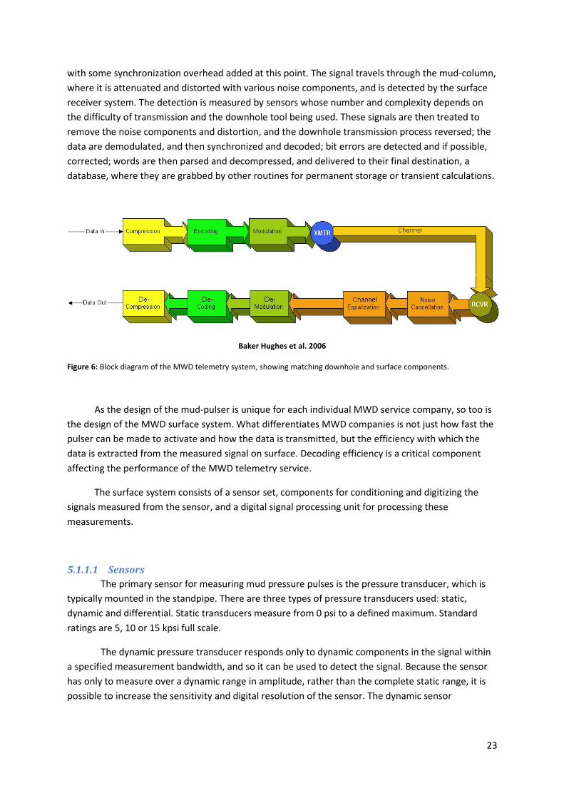
with some synchronization overhead added at this point. The signal travels through the mud-column,
where it is attenuated and distorted with various noise components, and is detected by the surface
receiver system. The detection is measured by sensors whose number and complexity depends on
the difficulty of transmission and the downhole tool being used. These signals are then treated to
remove the noise components and distortion, and the downhole transmission process reversed; the
data are demodulated, and then synchronized and decoded; bit errors are detected and if possible,
corrected; words are then parsed and decompressed, and delivered to their final destination, a
database, where they are grabbed by other routines for permanent storage or transient calculations.
Baker Hughes et al. 2006
Figure 6: Block diagram of the MWD telemetry system, showing matching downhole and surface components.
As the design of the mud-pulser is unique for each individual MWD service company, so too is
the design of the MWD surface system. What differentiates MWD companies is not just how fast the
pulser can be made to activate and how the data is transmitted, but the efficiency with which the
data is extracted from the measured signal on surface. Decoding efficiency is a critical component
affecting the performance of the MWD telemetry service.
The surface system consists of a sensor set, components for conditioning and digitizing the
signals measured from the sensor, and a digital signal processing unit for processing these
measurements.
5.1.1.1 Sensors
The primary sensor for measuring mud pressure pulses is the pressure transducer, which is
typically mounted in the standpipe. There are three types of pressure transducers used: static,
dynamic and differential. Static transducers measure from 0 psi to a defined maximum. Standard
ratings are 5, 10 or 15 kpsi full scale.
The dynamic pressure transducer responds only to dynamic components in the signal within
a specified measurement bandwidth, and so it can be used to detect the signal. Because the sensor
has only to measure over a dynamic range in amplitude, rather than the complete static range, it is
possible to increase the sensitivity and digital resolution of the sensor. The dynamic sensor

24
development has a high dynamic range of about 1000 psi, which yields a 5, 10 or 15 times increase in
digital resolution compared to the static sensors.
Flow meters have also been used in the standpipe to measure MWD telemetry, as have
annular pressure sensors. In a Venturi flow meter, flow passes through a constriction. Due to higher
flow velocity, there is a pressure drop which is measured using a differential pressure transducer. As
the flow velocity changes, so does the pressure drop.
Data enters the MWD surface system from many sources, not just from the pressure
transducers. For example, sensors may also be hooked up to measure Rotation-Per-Minute (RPM),
hookload, block height and surface torque. To further facilitate decoding, pump stroke counters and
a second pressure transducer may also be connected to the system.
5.1.1.2 Surface Systems
The pressure transducers are connected to a MWD surface system, where analog signal is
conditioned and digitized. The signal from the pulser is eventually extracted and decoded, and the
MWD data is stored and displayed. The complexity of the MWD surface system is dependent on the
MWD/LWD service being run, and decoding challenges increase with increasing data-rate and depth.
From a MWD view point, the major difference between older generations of surface systems
and more recent ones is the ability of the newer systems to recover a very small signal from the
pulser that is buried in background pressure noise. In systems with only one pressure transducer, or
a single flow sensor, decoding is limited to simple filtering to reduce noise. With the addition of
pump stroke counters, the ability to compensate for pressure signals generated by the mud pumps is
possible, and one of the major sources of pressure noise can be eliminated.
The development of sophisticated real-time Digital Signal Processing (DSP) routines
combined with high resolution analog to digital converters and a fast processing system makes it
possible to deliver reliable MWD mud-pulse telemetry at high data-rates at deep depths. This surface
platform provides not only noise cancellation, but also advanced digital signal processing to
characterize the telemetry channel and to remove telemetry channel distortion, referred to as
channel equalization.
5.1.2 Signal transmitted
MWD service companies employ their own commercial mud-pulsers to transmit the data
from downhole to surface. There are several different types of pulsers in use and we can classify
them based on the type of signal they can generate; discrete pulses or continuous-wave signals.
Discrete pulses can be either negative or positive, leading to the two classes of pulsers that can
generate only discrete pulses: the negative and positive pulsers. Rotary valve pulsers can generate
continuous-wave signals, and the shear-valve pulser is capable of generating both discrete and
continuous-wave signal. All mud-pulsers operate independent from the surface; there is no direct
electrical or mechanical connection from the downhole tools to surface.
25
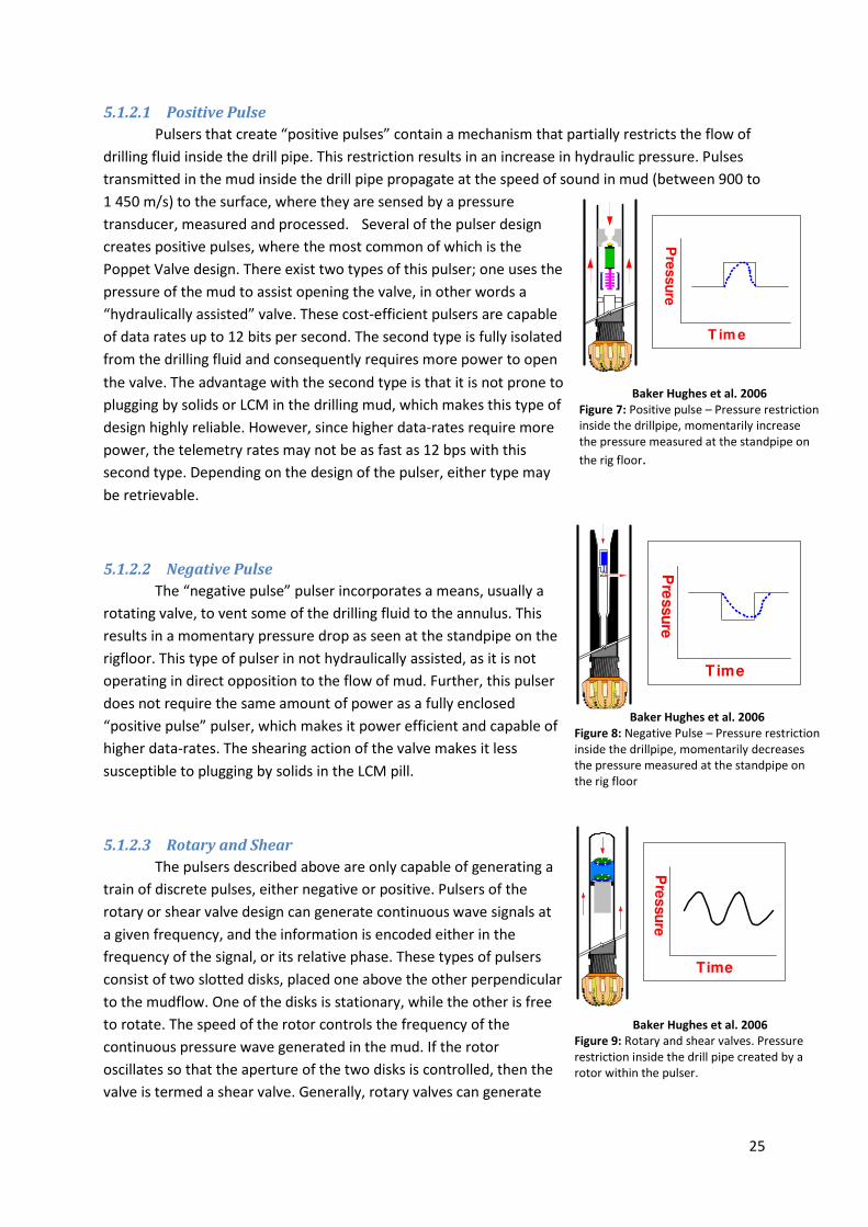
5.1.2.1 Positive Pulse
Pulsers that create “positive pulses” contain a mechanism that partially restricts the flow of
drilling fluid inside the drill pipe. This restriction results in an increase in hydraulic pressure. Pulses
transmitted in the mud inside the drill pipe propagate at the speed of sound in mud (between 900 to
1 450 m/s) to the surface, where they are sensed by a pressure
transducer, measured and processed. Several of the pulser design
creates positive pulses, where the most common of which is the
Poppet Valve design. There exist two types of this pulser; one uses the
pressure of the mud to assist opening the valve, in other words a
“hydraulically assisted” valve. These cost-efficient pulsers are capable
of data rates up to 12 bits per second. The second type is fully isolated
from the drilling fluid and consequently requires more power to open
the valve. The advantage with the second type is that it is not prone to
plugging by solids or LCM in the drilling mud, which makes this type of
design highly reliable. However, since higher data-rates require more
power, the telemetry rates may not be as fast as 12 bps with this
second type. Depending on the design of the pulser, either type may
be retrievable.
5.1.2.2 Negative Pulse
The “negative pulse” pulser incorporates a means, usually a
rotating valve, to vent some of the drilling fluid to the annulus. This
results in a momentary pressure drop as seen at the standpipe on the
rigfloor. This type of pulser in not hydraulically assisted, as it is not
operating in direct opposition to the flow of mud. Further, this pulser
does not require the same amount of power as a fully enclosed
“positive pulse” pulser, which makes it power efficient and capable of
higher data-rates. The shearing action of the valve makes it less
susceptible to plugging by solids in the LCM pill.
5.1.2.3 Rotary and Shear
The pulsers described above are only capable of generating a
train of discrete pulses, either negative or positive. Pulsers of the
rotary or shear valve design can generate continuous wave signals at
a given frequency, and the information is encoded either in the
frequency of the signal, or its relative phase. These types of pulsers
consist of two slotted disks, placed one above the other perpendicular
to the mudflow. One of the disks is stationary, while the other is free
to rotate. The speed of the rotor controls the frequency of the
continuous pressure wave generated in the mud. If the rotor
oscillates so that the aperture of the two disks is controlled, then the
valve is termed a shear valve. Generally, rotary valves can generate
Pre
ssu
re
T im e
Baker Hughes et al. 2006
Figure 7: Positive pulse – Pressure restriction inside the drillpipe, momentarily increase the pressure measured at the standpipe on
the rig floor.
Pre
ssu
re
Time
Baker Hughes et al. 2006
Figure 8: Negative Pulse – Pressure restriction inside the drillpipe, momentarily decreases the pressure measured at the standpipe on the rig floor
Pre
ssu
re
Time
Baker Hughes et al. 2006
Figure 9: Rotary and shear valves. Pressure restriction inside the drill pipe created by a rotor within the pulser.

26
only continuous-wave signals, while shear valves are very versatile and can generate both discrete
and continuous wave signals.
5.1.3 Signal Property Description
Mud-pulse telemetry is a complex process involving encoding the data from the MWD tools,
transmitting the encoded signal to surface, and decoding the data from the received signal. During
transmission from downhole to surface, the encoded signal is distorted and noise is added. Much of
the surface processing involves removing the noise and correcting for distortion so that the encoded
data can easily be decoded.
5.1.3.1 Signal theory related to MPT
Properties used to describe a sinusoidal waveform are its amplitude, frequency and phase.
Amplitude is the measurement from some base value, usually zero, but it might be referred to peak-
to-peak amplitude in which case the amplitude is measured from the minimum to the maximum of
the waveform. In measuring MPT pulse amplitudes, the peak-to-peak value is always used.
Frequency is simply the number of cycles of the sinusoidal waveform that occur per unit
time, and is measured in Hertz (Hz), which is the number of cycles per second. Phase is the relative
offset in sinusoidal waveforms measured in fractions of a cycle of the waveform; for example, if two
sinusoids are a 180 degrees out-of-phase, then they are shifted ½-cycle with respect to each other,
so that one is inverted with respect to the other.
Baker Hughes et al. 2006
Figure 10: The FFT algorithm is used to switch between the time-domain and frequency domain representation of
a signal. The time data is directly related to frequency data and knowing either one completely describes the signal.

27
A MPT signal can be represented in either the frequency domain or the time domain. In a
relationship established by Fourier, it was proved that any signal can be uniquely expressed as the
sum of sine waves of different frequencies and amplitudes. This concept means that no matter how
random, any signal can be created by adding specific sinusoidal signals together and conversely, that
the same signal can be broken down and represented as the sum of its sinusoidal parts. This allows
us to take a signal, like the standpipe pressure signal, and break it down by frequency into its
individual components for analysis.
This means that any waveform generated by a pulser can be approximated as the sum of a
set of sinusoids that have specific frequencies, amplitudes and phases. The mapping between the
pulser waveform (in the time domain) and its component sinusoids (in the frequency-domain) is
called the Fourier Transform. Efficient algorithms used to calculate the Fourier Transform of a signal
are called Fast Fourier Transform (FFT) algorithms.
Baker Hughes et al. 2008
Figure 11: A screen capture of the incoming raw signal in the top track and the corresponding frequency distribution in the lower track. A FFT algorithm is used to calculate the frequencies from the raw signal.
5.1.3.2 Groups of signals
There are two groups of signals that are used in the transmission of information: baseband
and passband signals. The transmission of information in a sequence of discrete pressure pulses is
known as baseband signaling. If the pulses are further modulated by a carrier signal, which shifts the
transmission bandwidth higher in frequency, then this is known as passband signaling.

28
Most commercially available mud-pulsers use baseband signaling. In some instances, rotary
or shear valve pulsers can use passband signaling in addition to baseband signaling. This capability is
important as it provides the opportunity to shift the transmission into frequency bandwidths that are
less affected by drilling noise, resulting in more reliable telemetry.
As an example, baseband signaling is affected by torque noise and the stick-slip behavior of
the drillstring. By using passband signaling we can move the signal clear of this noise source.
5.1.3.2.1 Baseband Transmission
There are basically two ways encoding the information sent by the downhole pulser. Either
by encoding the information directly so the presence and absence of pulses are signaling elements,
or by encoding the information in the position of the pulses. The first of these is referred to as Pulse
Code Modulation, and the second as Pulse Position Modulation.
5.1.3.2.1.1 Pulse Code Modulation (PCM)
In this method of encoding the information, the time-line is divided into intervals of equal
time, each of which is a bit-period. We directly translate the binary signal that is to be transmitted,
represented by a stream of 1’s and 0’s, into one of two states. For example, a binary one may be
encoded as the presence of a pulse within a bit-period and a binary zero as the absence of a pulse
within this period.
In this type of encoding, each bit-period contains a signaling element (a symbol) and the
transmission rate of these symbols is expressed in baud (“symbols per second”). The symbol rate
represents the transmission rate of symbols over the transmission channel.
The bit rate, in bits per second, is another measure of information transfer, and is the
number of binary digits (1’s and 0’s) delivered to the transmitter, and received at the receiver, per
second. In some systems, the bit rate is given by the inverse of the bit-period (T) times the number of
bits per symbol (b).
��� = �� (1)
MWD companies use a variety of coding schemes according to their individual requirements.
Example of PCM schemes are the SlitPhase and Miller codes.
In SplitPhase codes, a logical ‘1’ is represented by increase in signal level at the mid-point of a
bit period, while a logical ‘0’ is represented by a decrease in signal level. Obviously this pattern can
quite easily be represented by pressure pulses, and it is robust encoding type in high noise
environments (such as torsional stick-slip noise).
In Miller codes, a logical ‘1’ is represented by a change in signal level at the mid-point of a bit-
period. If a logical ‘0’ is preceded by a logical ‘1’ then there is no change in signal level at the bit-
period boundary; but if two logical zeros occur in sequence, then there is a change in signal level at
the bit-period boundary. Again, pulses can quite easily represent this pattern.
The frequency bandwidth of each PCM code is of interest since it indicates how hard an
MWD pulser must be driven to obtain a given bit rate. However, valve wear should be balanced

29
against decoding rehabilitee. That is, although the codes with more valve transition per unit time
result in greater valve wear, they have more clocking information and the surface system is better
able to maintain synchronization with the downhole system.
5.1.3.2.2 Pulse Position Modulation (PPM)
In Pulse Position Modulation, the information is encoded in the position of a number of
pulses within a specified time interval. Just as in the PCM techniques, the time-line is divided into
intervals of equal time, but here they are termed slots rather than bit-periods. However, unlike the
PCM techniques which are bit-based, this type of scheme is a word-based transmission system; a
word of K-bits is encoded M-pulse, which can occur in N-slots.
The rules for creating the pulse pattern to represent a word are relatively straight-forward; a
pulse is 1 ½ slots wide; pulses always start on a slot boundary; data pulses must be separated by at
least 1 ½ slots; and the last two slots of a word must be empty. For example a 7-bit word is
represented by 3 pulses in 17 slots, and an 8 bit word by 3 pulses in 19-slot.
While the calculation of the bit rate of a PCM code is straight forward, it is more difficult to
calculate the bit rate of a PPM code. We can, however, calculate it by assuming a word length of 16-
bits, which is represented by 6 pulses in 34 slots. As mentioned previously, each pulse is 1 ½ slots
wide: so the 16-bit word is transmitted in 2/3*34 pulse widths. The relationship between bit rate and
pulse width is:
��� = �∙�∙�� ∙
� = �.�� � ≈ �
� � (2)
Pulse Position Modulation is very efficient in terms of pulses per bit, it requires only 6-pulses
to transmit 16 bits. Comparisons with the PCM schemes, SplitPhase require an average of 21 pulses
to transmit 16 bits, while Miller requires an average of 11.
One additional advantage using PPM codes is that they come with built-in error detection.
The pulse pattern rules limit the possible location of valid pulses, and can be used to discriminate
between valid pulses and those created by noise source.
5.1.3.2.3 Passband Transmission
If the baseband signal described in the previous section is modulated with a signal which has
a constant carrier frequency, then the resultant signaling is termed passband. Any baseband signaling
can be made into a passband signal by modulating it with a carrier signal.
There are three subset of passband signaling that are of interest: frequency modulation,
phase modulation and amplitude modulation. The last of these is a hybrid between passband and
baseband, but it is included in this section because it involves a carrier signal.
5.1.3.2.3.1 Amplitude Modulation
Amplitude-Shift-Keying (ASK) is the use of an amplitude modulated waveform to carry digital
information. A baseband signal may be thought of as a sequence of alternating pulses and gaps. In
ASK, a waveform of a single frequency is used to represent a pulse and no signal is sent for a gap (the
transform may be inverted so that a gap is represented with a waveform of known signal, a pulse
with no signal). Any of the baseband signals (Pulser Code or Pulse Position Modulations) can be
represented by ASK. While in theory any frequency can be used for the waveform, one of the
30
restrictions is that the waveform demonstrates the property of continuous phase. This property
results in lower energy requirements by the pulser, and lower energy losses while transmitting the
waveform through the drilling fluid. Continuous phase means that the phase of the signal changes
smoothly at the boundary of a pulse. For many mud-pulsers, valid ASK frequencies are given by the
inverse of the pulse width times an integer.
5.1.3.2.3.2 Frequency Modulation
Frequency-Shift-Key (FSK) is the use of a frequency modulated waveform to carry digital
information. If the pulse train is thought of as a sequence of pulses and gaps, then a first frequency
represents a pulse, and a second frequency represents a gap. The order of the frequencies is not
important, so long as it is known at both the transmitter and receiver. As with ASK, the phase should
change continuously at pulse boundaries where two different frequencies meet. This type of FSK is
termed continuous-phase FSK, or CPFSK for short. Another restriction imposed with mud-pulse
telemetry is that transition between signals takes place at either the maximum or minimum
amplitude, to conserve energy in the generation of the signal. This restriction also ensures that the
two frequencies are orthogonal. They do not disturb each other during transmission and are easily
distinguished at the detector on surface. This is an extremely valuable property for the transmission.
5.1.3.2.3.3 Phase Modulation
Phase-Shift-Key (PSK) is the use of a phase modulated waveform to carry digital information.
In PSK transmission the frequency is kept constant, and the phase of the signal is changed at signal
boundaries. With binary PSK (only two states to be represented, 0 or 1), the phase difference is 180-
deg. As with ASK and FSK transmission, the phase of the signal is continuous at symbol boundaries.
The carrier frequency is the frequency used in generating the PSK waveform. The signal is
concentrated in a bandwidth about the carrier, and the extent of the bandwidth depends on the bit-
rate and the baseband code being modulated.
5.1.3.2.4 Comparison of Modulation Methods
The chosen modulation mode will depend on the drilling environment. FSK can operate in
poorer reception conditions, and can handle about a 30% lower signal-to-noise ratio at the receiver
than either PSK or ASK. FSK has also the ability to switch to ASK demodulation at the receiver,
without changing from FSK transmission. Should one frequency become corrupted by drilling noise;
then FSK has the ability to cancel amplitude modulation noise, which makes it relatively robust. A
disadvantage with FSK is that the bandwidth is relatively high compared to PSK. So if the telemetry
bandwidth is reduced due to noise and problems transmitting the signal through the mud, then PSK
is a better option.
5.1.4 Signal Attenuation
One of the challenges that successful MPT decoding has to overcome is the attenuation of the
signal with depth. Increasing depth has a significant influence on the amplitude of the signal
measured to surface. [1] This is also influenced by the mud properties. Due to its compressional
properties, oil based mud would give back a smaller signal compared to water based mud. Delivering
adequate signal strength at the tool, so that it can be detected at surface, is an important property of
the mud-pulser. Successful decoding at extended depths becomes a significant challenge, and in
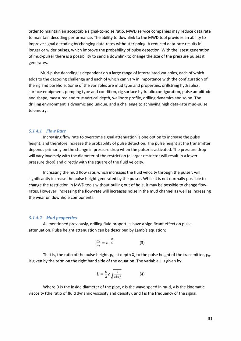
31
order to maintain an acceptable signal-to-noise ratio, MWD service companies may reduce data rate
to maintain decoding performance. The ability to downlink to the MWD tool provides an ability to
improve signal decoding by changing data-rates without tripping. A reduced data-rate results in
longer or wider pulses, which improve the probability of pulse detection. With the latest generation
of mud-pulser there is a possibility to send a downlink to change the size of the pressure pulses it
generates.
Mud-pulse decoding is dependent on a large range of interrelated variables, each of which
adds to the decoding challenge and each of which can vary in importance with the configuration of
the rig and borehole. Some of the variables are mud type and properties, drillstring hydraulics,
surface equipment, pumping type and condition, rig surface hydraulic configuration, pulse amplitude
and shape, measured and true vertical depth, wellbore profile, drilling dynamics and so on. The
drilling environment is dynamic and unique, and a challenge to achieving high data-rate mud-pulse
telemetry.
5.1.4.1 Flow Rate
Increasing flow rate to overcome signal attenuation is one option to increase the pulse
height, and therefore increase the probability of pulse detection. The pulse height at the transmitter
depends primarily on the change in pressure drop when the pulser is activated. The pressure drop
will vary inversely with the diameter of the restriction (a larger restrictor will result in a lower
pressure drop) and directly with the square of the fluid velocity.
Increasing the mud flow rate, which increases the fluid velocity through the pulser, will
significantly increase the pulse height generated by the pulser. While it is not normally possible to
change the restriction in MWD tools without pulling out of hole, it may be possible to change flow-
rates. However, increasing the flow-rate will increases noise in the mud channel as well as increasing
the wear on downhole components.
5.1.4.2 Mud properties
As mentioned previously, drilling fluid properties have a significant effect on pulse
attenuation. Pulse height attenuation can be described by Lamb’s equation;
� � = ���
� (3)
That is, the ratio of the pulse height, px, at depth X, to the pulse height of the transmitter, p0,
is given by the term on the right hand side of the equation. The variable L is given by:
� = �� �� �
��� (4)
Where D is the inside diameter of the pipe, c is the wave speed in mud, v is the kinematic
viscosity (the ratio of fluid dynamic viscosity and density), and f is the frequency of the signal.
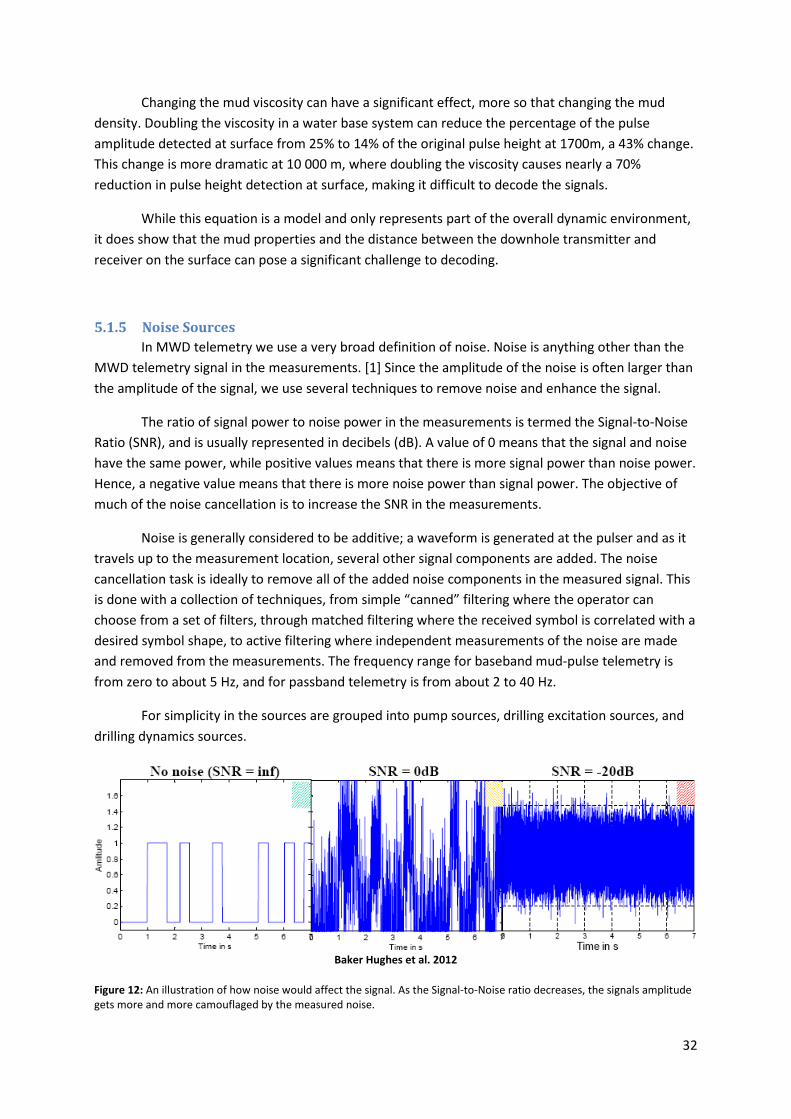
32
Changing the mud viscosity can have a significant effect, more so that changing the mud
density. Doubling the viscosity in a water base system can reduce the percentage of the pulse
amplitude detected at surface from 25% to 14% of the original pulse height at 1700m, a 43% change.
This change is more dramatic at 10 000 m, where doubling the viscosity causes nearly a 70%
reduction in pulse height detection at surface, making it difficult to decode the signals.
While this equation is a model and only represents part of the overall dynamic environment,
it does show that the mud properties and the distance between the downhole transmitter and
receiver on the surface can pose a significant challenge to decoding.
5.1.5 Noise Sources
In MWD telemetry we use a very broad definition of noise. Noise is anything other than the
MWD telemetry signal in the measurements. [1] Since the amplitude of the noise is often larger than
the amplitude of the signal, we use several techniques to remove noise and enhance the signal.
The ratio of signal power to noise power in the measurements is termed the Signal-to-Noise
Ratio (SNR), and is usually represented in decibels (dB). A value of 0 means that the signal and noise
have the same power, while positive values means that there is more signal power than noise power.
Hence, a negative value means that there is more noise power than signal power. The objective of
much of the noise cancellation is to increase the SNR in the measurements.
Noise is generally considered to be additive; a waveform is generated at the pulser and as it
travels up to the measurement location, several other signal components are added. The noise
cancellation task is ideally to remove all of the added noise components in the measured signal. This
is done with a collection of techniques, from simple “canned” filtering where the operator can
choose from a set of filters, through matched filtering where the received symbol is correlated with a
desired symbol shape, to active filtering where independent measurements of the noise are made
and removed from the measurements. The frequency range for baseband mud-pulse telemetry is
from zero to about 5 Hz, and for passband telemetry is from about 2 to 40 Hz.
For simplicity in the sources are grouped into pump sources, drilling excitation sources, and
drilling dynamics sources.
Baker Hughes et al. 2012
Figure 12: An illustration of how noise would affect the signal. As the Signal-to-Noise ratio decreases, the signals amplitude gets more and more camouflaged by the measured noise.

33
5.1.5.1 Pumps
Signals generated by the pumps are a major source of noise in the pressure measurements.
With a triplex pump pumping at 90 strokes per minute (SPM), a large signature is generated at three
times this frequency, or:
!"#�$�% �'(� )"�*'�+�, = �∙-./� 012 = 4.556 (5)
This signal is not sinusoidal and several harmonics may be present at 6, 9, 12 and so on, times
the stroke rate. If the pump is not in good condition, a significant fundamental signal may also be
present. In this example, this would be at 1.5 Hz.
Frequencies generated by the pumps appear at the top half of the baseband frequency
range, and within the passband frequency range. In deep wells the telemetry signal may be quite
small in amplitude and impossible to visually recognize in the raw measured data since the pump
noise is high in amplitude. The pump noise may be ten-times or greater in amplitude than the
downhole pressure pulses.
Aside from frequency interference from individual pumps, two or more pumps being run
simultaneously can add noise due to amplitude modulation of the signals from the individual pumps.
This amplitude modulation results in a signal at the “beat frequency” which is the difference
between the individual pump rates. For example, if two triplex pumps are operating at 60 SPM and
50 SPM respectively, a low frequency beat signal might be observed in the standpipe at 0.167 Hz (60-
50)/60, or three times this, 0.5 Hz. This signal will fall well within the mud-pulse baseband signal
bandwidth.
5.1.5.2 Drilling Excitation
Drilling excitations can be regarded as sources of noise for mud-pulse telemetry, but are
usually of lesser importance than the mud pumps. These could include excitations caused by
drillstring rotation and mud motors. When the string is rotated it will move laterally, and a periodic
excitation with the same frequency as the drillstring rotation may be coupled into mud. This may
result in some distortion of the MWD signal.
The rotor in the mud motor will generate an excitation at a frequency given by the number of
lobes on the rotor times the motor-speed. This excitation couples into the mud, and has been
measured downhole. It can, therefore, add noise and distortion to the MWD signal.
5.1.5.3 Drilling Dynamics
Torsional oscillation of the drillstring is a principal source of noise. This is a periodic motion of
the drillstring in torsion, and is due to the fact that the large mass of the BHA is on the end of a
slender length drillpipe. If there is an increase in friction at the bit, or in the BHA, then the drillstring
may start to oscillate at its first natural torsional frequency. This is a common mode of behavior for
any drillstring, and is referred to as “torsional oscillation” of the drillstring. Its periodicity is generally
longer than about 2 seconds; in other words, it has a frequency of less than 0.5Hz.

34
If the oscillations become severe, and the drillstring comes to a complete stop, then the
phenomenon is referred to as stick-slip. The periodicity of the stick slip behavior will be longer than
that of the torsional oscillation, with cycles longer than 5 seconds (0.2 Hz) being common. The longer
the drillstring and the more severe the stick-slip behavior, the longer the stick-slip cycle becomes. In
extreme cases, the bit and drillstring may rotate backwards and damage the bit.
Stick-slip and torsional oscillation noise fall within the frequency bandwidth used by
baseband signaling, and can be extremely disruptive to baseband telemetry. There are several ways
to minimize the impact that this noise has on telemetry. If vibration stick-slip is detected, this should
be reacted to by either raising the RPM or lowering the Weight-On-Bit (WOB), or both, in an attempt
to reduce the severity of the torsional motion. This is mainly to protect the BHA, and there are some
cases, such as dropping angle, where the severity of the stick-slip behavior cannot be reduced. Then
a high-pass filter could be applied to remove the frequencies where the noise appears.
High-pass filtering attempts to remove the interfering stick-slip signal from the measured
pressure signal, and can be successful when the interference is very sinusoidal (as in pure torsional
oscillations) and is at a very long frequency (as for long drillstrings). When the frequency of the
torsional oscillation is high, the high-pass filter will remove too much of the baseband signal power,
and there will not be sufficient signal remaining for reception. In this case, increasing the bit rate in
combination with high-pass filtering may result in continued MWD transmission, since majority of
the power in the MWD bandwidth may be moved above the cut-off frequency of the high-pass filter.
There is one instance when this strategy will not work, and that is when fully developed stick-
slip is present. This motion is non-sinusoidal and contains many harmonic frequencies. It is doubtful if
increasing the data-rate will move the MWD transmission bandwidth clear of these interfering
frequencies. With baseband transmission, all that will work in these circumstances is to detect stick-
slip motion and if possible change the drilling parameters to remove it.
Another phenomenon that may include drilling noise in the mud stream and interfere with
the mud-pulse transmission, is operating at the natural frequency of the drillstring. This is termed the
critical speed of the drillstring, and can cause resonant behavior of the drillstring. Prediction of the
critical rotation speeds of drillstrings are best done using critical speed modeling software if
available. These will predict the drillstring rotations to avoid. Critical speeds can also be avoided by
real-time monitoring using vibration stick-slip or advanced drilling dynamics services, like Baker
Hughes CoPilot. The drilling dynamic service also includes the ability to detect drillstring whirl, which
is off-center rotation of the BHA, and can generate interference at frequencies 2 to 4 times greater
than the drillstring rotation rate. These frequencies will interfere with passband signaling.
5.1.5.4 Other sources of noise
Reflections within the transmission system can be quite destructive. Reflections are created
at each ID change that the up-traveling MPT waveform encounters, resulting not only in a loss of
signal power, but also in interference with succeeding symbols. It can be quite severe if the change in
ID is abrupt, which often occurs at a change in pipe sections. The best way to combat drillstring
reflections is through drillstring design practices. This can be modeled to help predict the impact and
recommended potential alternatives.

35
One other potential source of reflections is at the pumps in the upper end of the hydraulic
system. A pulsation damper is used to limit the amplitude of the pump stroke pressure pulses, like a
hydraulic shock absorber, which also has the effect of modifying the top end of the transmission
system. The pressure in the pulsation dampener can either be increased or decreased within the
operating range of the device to change top boundary condition from a soft system (high pre-charge)
to a stiff system (low pre-charge). In a soft system the reflected pulse is inverted; in a stiff system the
reflected pulse is not inverted. If the system is too soft, the down-traveling (reflected) pulses can
potentially cancel out the up-traveling pulses at the sensor. Conversely, if the system is to stiff, the
down-traveling mud pulses add in amplitude to the up-traveling pulses, thereby making the easier to
detect. However, the amplitude of the pump stroke signal is also increased. The solution is to
maximize the signal-to-noise ratio (SNR) at the measurement location; it is probably better with wide
pulse widths in a stiffer system is since the increase in pulse height is larger than the increase in
pressure amplitude of the pump stroke pulses.
Baker Hughes et al. 2008
Figure 13: An example of how the signals pressure pules might appear after the surface software system has removed noise from the signal. The upper track show the theoretical pressure pulses, while the lower track show the processed pressure data. In this example, it can be seen clearly where the signal amplitudes are located, hence a valid downhole measurement can be decoded.
5.1.6 Noise cancellation
As described previously, torque noise due to torsional oscillations can be cancelled by a
combination of methods, but the most direct method is high-pass filtering. A variety of high-pass
filters exist for this purpose. Additional low-pass or band-pass filters may be deployed to isolate the
signal bandwidth from noise sources. This has the effect of increasing the SNR at the input to the
demodulators or pulse detectors.
36
5.1.6.1 Pump Noise Cancellation (PNC)
Pump noise cancellation algorithms require pump strobe signals from each active pump. The
signature for each pump is assembled by marking the time at which successive pump strobes occur,
and stacking the pressure records between the strobes. This results in random noise being cancelled
out, and the pump signature emerges.
This pump signature is the subtracted from the raw pressure data; the result is the measured
pressure signal with the signal from the pump cancelled out. In the ideal case this resultant signal
contains only the signal from the MWD pulser. Pump noise cancellation algorithms are needed for
any high bit-rate baseband signaling, severe decoding issues and for any passband signaling.
Depending on the water depth and length of the riser, a pump might be used as a booster, to
improve the hole-cleaning in the bigger ID riser. The rig pump used for this is not connected through
the standpipe, and will not add any noise to the signal. It is therefore important not to add this as a
part of the PNC calculation, since removing the theoretical calculated noise from this pump, could
cancel out some of the transmitted downhole signal.
5.1.6.2 Down-Traveling Noise Cancellation
Down-traveling signals that can originate from the surface equipment interfere with the up
traveling mud-pulses and can cause significant distortion. These signals may originate from
reflections of the original mud-pulses caused by the mud pumps, pulsation dampers, pipe diameter
changes, trapped air or gas in surface lines, and so on. Echoes of the original pulse have the effect of
attenuating and distorting upcoming signals. When the measured signal strength is below 0.5 bars,
this can have a very negative effect on the ability to successfully decode the data. The algorithm to
cancel these down-traveling signals requires the input from two pressure transducers spaced some
distance apart in the surface lines. The pressure transducers must preferably be of the same type and
the same make.
In the algorithm, the measurement at the upstream transducer is delayed by a time
increment, and then subtracted from the downstream transducer. This has the effect of cancelling all
down-traveling waveforms which take the time increment to travel between the two transducers,
and the remaining signal is the time delayed difference of the up traveling waveforms. When the
remaining signal is high-passed and integrated, the up traveling waveforms are recovered. The time
delay between the upstream and downstream transducers is determined by cross-correlating
measurements from the two transducers.
Since the pump signals are known to be traveling down the drillstring, this algorithm is quite
good at removing them. It also removes all other down-traveling signals, such as those due to
reflections, and can result in considerable clean-up of the surface measurement. This application is
not only required to deliver high speed telemetry, but is generally very useful in problematic
decoding environments where noise is significant.
37
5.1.6.3 Channel Equalization
One surface processing task is to remove any distortion of the waveforms that may have
occurred during their transit through the telemetry channel. A number of different techniques are
used for this. One of these is called matching filtering, and is described below to give an example of
how they could work.
5.1.6.3.1 Matched filtering
Assuming that a rectangular shaped pulse with very abrupt edges is generated by the pulser
downhole. As it is transmitted through the mud channel it gets banged around, loses some of its
original crispness, and gets spread out. By the time it reaches the surface and gets detected by the
surface sensors it has the shape of a shark fin.
In order to detect the pulse in an optimal fashion, a matched filter is correlated with the
arriving pulse-train; the best matched filter is one that looks exactly like the arriving pulse. The
implications of this is that no matter what distortion is added in the mud channel; if a representative
pulse can be isolated at the receiver, then it can be used to detect succeeding pulses.
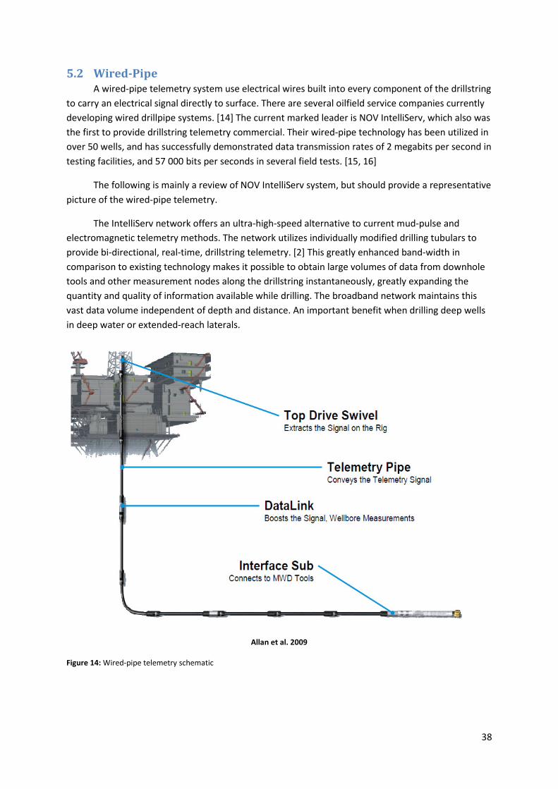
38
5.2 Wired-Pipe
A wired-pipe telemetry system use electrical wires built into every component of the drillstring
to carry an electrical signal directly to surface. There are several oilfield service companies currently
developing wired drillpipe systems. [14] The current marked leader is NOV IntelliServ, which also was
the first to provide drillstring telemetry commercial. Their wired-pipe technology has been utilized in
over 50 wells, and has successfully demonstrated data transmission rates of 2 megabits per second in
testing facilities, and 57 000 bits per seconds in several field tests. [15, 16]
The following is mainly a review of NOV IntelliServ system, but should provide a representative
picture of the wired-pipe telemetry.
The IntelliServ network offers an ultra-high-speed alternative to current mud-pulse and
electromagnetic telemetry methods. The network utilizes individually modified drilling tubulars to
provide bi-directional, real-time, drillstring telemetry. [2] This greatly enhanced band-width in
comparison to existing technology makes it possible to obtain large volumes of data from downhole
tools and other measurement nodes along the drillstring instantaneously, greatly expanding the
quantity and quality of information available while drilling. The broadband network maintains this
vast data volume independent of depth and distance. An important benefit when drilling deep wells
in deep water or extended-reach laterals.
Allan et al. 2009
Figure 14: Wired-pipe telemetry schematic

39
Within the BHA, a short sub contains a communications interface between the MWD and
IntelliServ data protocols; it is at this point that the communications protocol of the service company
is “repackaged” to allow transmission on the IntelliServ network wire to surface. The reserve occurs
on surface via another device, which allows the MWD service company to retrieve its downhole data.
In order to use wired-pipe telemetry, changes have to be made to the drilling equipment and
MWD/LWD transmission. All of the components above the interface sub needs to be wired and the
Top-Drive System modified. Also the configuring of MWD/LWD Transmission Lists will be changed,
due to the increased data steam.
5.2.1 Wired pipe transmission line.
In general, The IntelliServ Network system transmission line is composed of four main
components. [15]
5.2.1.1 Interface sub
The Interface sub connects to the MWD/LWD and RSS tools to allow bi-directional
communication of logs and commands. Each service company manufactures an interface sub jointly
with IntelliServ. The interface sub is owned by the service company, and is currently provided either
by Baker Hughes, Schlumberger D&M, Sperry Drilling Services or Weatherford. Although slight
variations exist between the vendors, interface subs are generally consistent across the industry.
Baker Hughes INTEQ developed the industry’s first interface sub, linking the tools in the
INTEQ BHA to the IntelliServ Network in 2003. [17] The primary objectives was to take full advantage
of the drillstring telemetry network`s high-speed capabilities, but also to minimize the impact on
existing MWD tool architecture and operation. This resulted in a decision to keep the current MWD
data bus as a communication backbone for all components connected below the telemetry network.
Hence, no modifications are necessary to interface existing MWD tools to the network, allowing fully
functional MPT tools to be deployed parallel with the drillstring network. To ensure the drillstring
telemetry remained transparent from MWD perspective, simple protocol converters where
established at the downhole tool and surface computers interface.
An interface sub provides a physical and electrical crossover between the MWD/LWD tool
string and the telemetry network. The interface sub contains both a MWD micro-controller board
and a telemetry network repeater board with a sheared battery power source. The box end contains
a telemetry network inductive coupler and the pin end contains a MWD tool coupler.
At surface, data from the downhole tools is delivered to the service company via the
IntelliServer. The tool data is simply encapsulated within the network package at the interface sub,
transmitted to surface and then unwrapped for delivery to the MWD acquisition computer system by
the network surface server.

40
5.2.1.2 The wired-pipe
The drillstring telemetry network
comprises conventional drilling tubular
modified to incorporate a high speed, low loss
data cable running through the length of each
joint. [18] The cable terminates at unique,
inductive coils that are installed in the pin and
corresponding box shoulder of every
connection and transmit data across each tool
joint interface. The double-shoulder connection
configurations, used in the second-generation
IntelliPipe, provide an ideal location for coil
placement, with each coil installed in a
protective groove in the secondary torque
shoulder. When two connections are threaded
together, the pin end coil in one joint is brought
in close proximity with the box end of another.
The coils are circular in design and require no special orientation of the tool joints at make-up.
In addition to drillpipe, the simplicity of design allows conversion of other common drilling
tubular in various sizes to support data transmission. Heavy weight drillpipe, drill collars, drilling jars,
string stabilizers, roller reamers and accessories machined with double shouldered connections have
all been modified to support the network. [2]
The signal conductor may be in form of an armored high strength, stainless steel, coaxial data
cable stretched on the inside of the pipe wall,
or it could be a data-cable embedded in the
drill pipe wall. The first solution enables easy
access to the data cable for maintenance or
replacement. [3] The solution with a data cable
imbedded in the pipe body is advantageous
with regards to cable wear and interference
with objects traveling on the inside of the
drillpipe such as wiper darts or wireline
equipment. In a drillpipe configuration, the
conduit passes through the body of the tool
joint and then enters into the internal diameter
of the drillpipe at the internal upset. The
conduit is held under tension in the drillpipe
tube, maintaining its position against the tube
wall under most conditions and minimizing interference with mudflow or deployment of tools
through the center of the assembly. The cable runs through the pipe without affecting drillpipe
properties. However, a stabbing guide is required, but depending on the training of the rig-crew,
there should be no additional tripping time. The overall drillpipe and tool joint design achieves the
goal of being transparent to normal rig operating procedures. Double-shouldered connections do
require a higher make-up torque then standard API connections, but with this exception, intelligent
Reeves et al. 2006
Figure 15: Cutaway of Double-Shouldered Pin Tool Joint Showing Location of Inductive Coil
Reeves et al. 2006
Figure 16: Cutaway of Made-Up Drill Pipe Tool Joint Connection Showing Location of Inductive Coils and Data Conduit

41
tubular are identical in mechanical and hydraulic performance to non-wired double-shouldered
drilling tubular. In contrast to the connections in the MWD tool string, any thread compound
chemistry can be used.
Once made up, the coils come near each other and induce the signal down the pipe without
direct contact. An electromagnetic field associated with the alternating current signal transmitted
through the cable is responsible for transmitting data. As the alternating electromagnetic field from
one coil induces an alternating current in the nearby coil, data is transmitted from one tubular to the
next.
5.2.1.3 Signal repeaters
As there is some signal loss over the wire, battery powered signal repeaters are added
periodically to increase the signal. Commonly, these electronic elements are known as booster
assemblies, and are provided by NOV under the name IntelliLink. Their function is to boost the signal
and ensure a proper signal-to-noise ratio and avoid data loss. The separation between the repeaters
controls the maximum bit rate, and is integrated in the drillstring with spacing typically between 400-
500 meters.
Booster joints consists of a 1.2 meter long sub containing a lithium battery powered
electronics package threaded on a specially manufactured drillpipe joint, such that the full booster
assembly measures the same total length as a standard drillpipe joint with an extended length lower
tool joint. The lithium batteries will add some limitations to the IntelliServ Broadband Network, with
a lifetime typically around 90 days, and a temperature limitation of a 150⁰C.
These repeaters also serve as individually addressable nodes within the telemetry network.
Sensors are located at each signal repeater and provide a standalone measurement at its location. In
the IntelliLink the commercially available sensors measure the absolute value of temperature and
pressure. However, other measurements are on the roadmap to be developed, such as vibration,
strain and caliper.
5.2.1.4 Top drive swivel
A key component of The IntelliServ Network is the Top Drive Interface Swivel which provides
the interface between rotating and stationary environments. It is installed at the lower end of the
top drive assembly, often replacing an existing saver sub. It consists of a telemetry-enabled sub
inductively coupled to a non-rotating member. Network traffic moves through the sub and into the
swivel, which in turn is connected to IntelliServ’s data acquisition system via surface cabling.
5.2.2 Advantages of a wired-pipe Network
The main advantage of a wired-pipe network is the greatly enhanced band-width in
comparison to existing technology; which makes it possible to obtain large volumes of data from
downhole tools and other measurement nodes along the drillstring instantaneously. This will greatly
42
expand the quantity and quality of information available while drilling, and save expensive rig-time
for the costumer.
The wired-pipe drillstring works independently of the medium present, and can transmit data
regardless of fluid environment - hydrocarbon, water, air or foam – or even while suffering total
losses. There is no loss of signal strength along the drillstring, and no interference from acoustic
noise or the operation of other equipment such as mud pumps.
The large volumes of data could change the application of the MWD/LWD measurements in
several ways. While some of the new application areas already have been utilized commercially,
there are several other application areas that could be exploited and improved with this technology.
5.2.2.1 Wellbore positioning
The use of wired-pipe potentially allows both the efficiency and quality of the survey process
to be improved. Data can be transmitted to full sensor accuracy in real-time for near-instantaneous
verification. This will save time and allow immediate identification of poor quality data such as that
resulting from drillstring movement during survey the acquisition. It will also allow multiple
directional sensors placed within the MWD system to be used continuously in real-time while drilling
ahead. With the development of suitable algorithms, this will allow fewer conventional survey
stations to be required without deteriorating uncertainty, or allow an improvement in wellbore
positioning uncertainty without the requirement for increased conventional surveying operations.
The near instantaneous communication with the downhole system also allows downlinks to
be performed without interrupting the drilling process. Hence, there is no need to take any
consideration to limit the downlinks while steering the well.
5.2.2.2 Flow-off data
With battery powered MWD tools in the BHA, it is also possible to obtain the measurements
from the tripping as well. Monitoring the annular pressure would improve the control of swab and
surge during tripping, and could be used to optimize the tripping speed.
During LOT/FIT tests a complete pressure profile of the well could be provided. Especially
during Leak-off-tests (LOT), this could be useful in verifying the Leak-off pressure for the formation.
The formation usually starts to leak-off at a pressure lower than the maximum pressure seen in the
test. With MPT it is only possible to get the maximum measurement during the flow-off events.
There will be no communication to the downhole tools during the actual connection of a new
drillpipe. When picking up a new stand, the top drive swivel is not connected to the wired-pipe
network before the new stand is added to the drillstring.
5.2.2.3 Optimizing Drilling Parameters for Efficient Drilling
A wired-pipe delivers a more complete visualization of the downhole dynamic environment
in real-time, allowing monitoring of a far wider range of drilling dynamic variables. This provides the

43
opportunity to identify and diagnose damaging vibration events more quickly with higher accuracy
for immediate and correct parameter adjustment to avoid damage to the downhole toolstring or
borehole. The effect of any parameter adjustment can then be seen more clearly and immediately as
opposed to tracking trends in vibration levels which can take 10 minutes or more to become
apparent with conventional mud-pulsed updates.
Manning et al. 2008
Figure 17: Screen capture of surface and downhole drilling dynamics data through an interval of very difficult reading. The real-time data displayed above was updated every 10 seconds using wired-pipe telemetry.
5.2.2.3.1 Improved ROP
An improved visualization includes the opportunity to continuously monitor parameters,
which have an immediate effect on instantaneous and gross ROP, such as downhole WOB. With
continuously transmitted downhole WOB information, any tendency for the drillstring to hang up can
be immediately identified and corrected with minimal impact upon drilling performance. Coupled
with continuous downhole torque measurements, this can be used to determine the dull condition of
the bit and removes some uncertainty as to when it is time to trip to change the drill bit.
5.2.2.3.2 Vibration Management
With wired-pipe a more complete view of stick-slip, axial and torsional vibration is available.
It can be used real-time to more rapidly identify and more accurately migrate the undesired vibration
44
levels for increased drilling performance. This will for instance give better drill bit cutting action, and
lower risk of equipment and formation damage.
5.2.2.3.3 Improved Hole Quality
A unique capability of Baker Hughes’ CoPilot advanced drilling optimization service is the
measurement of BHA bending moment which is a measure of the side force acting on the BHA. This
measurement can be used to accurately estimate borehole curvature and has also proven to be
valuable when drilling through highly interbedded formation sequences where formation strength
varies greatly across interfaces. Under these conditions, the drill bit can take the path of least
resistance while drilling ahead and form a high local dogleg in the hole. Left unattended, this can
cause damage to the drillstring components, as well as risk damage to completion strings when run
through it. In areas where this drilling environment exists, field specific drilling procedures are
employed which use the BHA bending moment measurement to identify generation of dogleg,
measure its magnitude and, if necessary, reduce it – monitoring the effectiveness of the operation in
real-time. It can take significant time to reduce the severity of a “typical” high local dogleg by
reaming and sometimes be difficult to reduce it to a safe level to allow drilling to continue. This is
dependent upon the size of the dogleg which builds up in the hole. A high local dogleg will be a
function of both the severity of the initial deflection and how quickly the generation of the dogleg is
identified. Using wired-pipe will enable rapid identification of a dogleg being formed in hole, allowing
for appropriate corrective actions, e.g. drilling parameter adjustment, to be implemented. Hence, the
severity of the high local dogleg is reduced, which eliminate the need for further remedial action or
at least saves time and enhancing the effectiveness of the remedial action.
When short gauge drill bits with active cutting structures are used, there is a risk that a
“cyclic” hole is drilled. [2] This is commonly termed “hole-spiraling” and is a natural phenomenon in
boring process. The effects of hole-spiraling can; deteriorate the quality of the LWD data (especially
shallow reading borehole images), increase friction in the borehole, required increased reaming on
BHA trips or cause problems running subsequent BHA`s of different geometry and casing strings. By
increasing the friction in the borehole, hole-spiraling can negatively effect on-bottom drilling
efficiency and increase time required to trip out of hole. Hole-spiraling cannot normally be
confidently identified in real-time due to insufficient real-time data density, especially when drilling
at a high ROP. It is normally only identified from processed memory data such as borehole images,
where regular diagonal stripes can be seen across the log with mask features which would otherwise
be clearly seen. Borehole spiraling can also be identified from sinusoidal oscillations of BHA bending
moment or continuous inclination data from memory. With wired-pipe, the onset of hole-spiraling
could be immediately identified in real-time from any one of a number of sensors including
continuous inclination, borehole images or BHA bending moment data. Variation in drilling
parameters can then be made to eliminate the cyclic effect and, if not effective, assist in the decision
to POOH to change to a different drill bit or continue drilling ahead, monitoring the effect in real-
time.
5.2.2.3.4 Borehole Stability Prediction and Monitoring
LWD acoustic measurements, particularly the formation shear velocity, can also be used to
compute rock strengths for wellbore geomechanics applications. [2] The rock strengths can be used
for determining fracture gradients, as well as identifying potential borehole breakout zones which
could lead to stuck-pipe incidents. However, full acoustic waveforms are required at the surface for
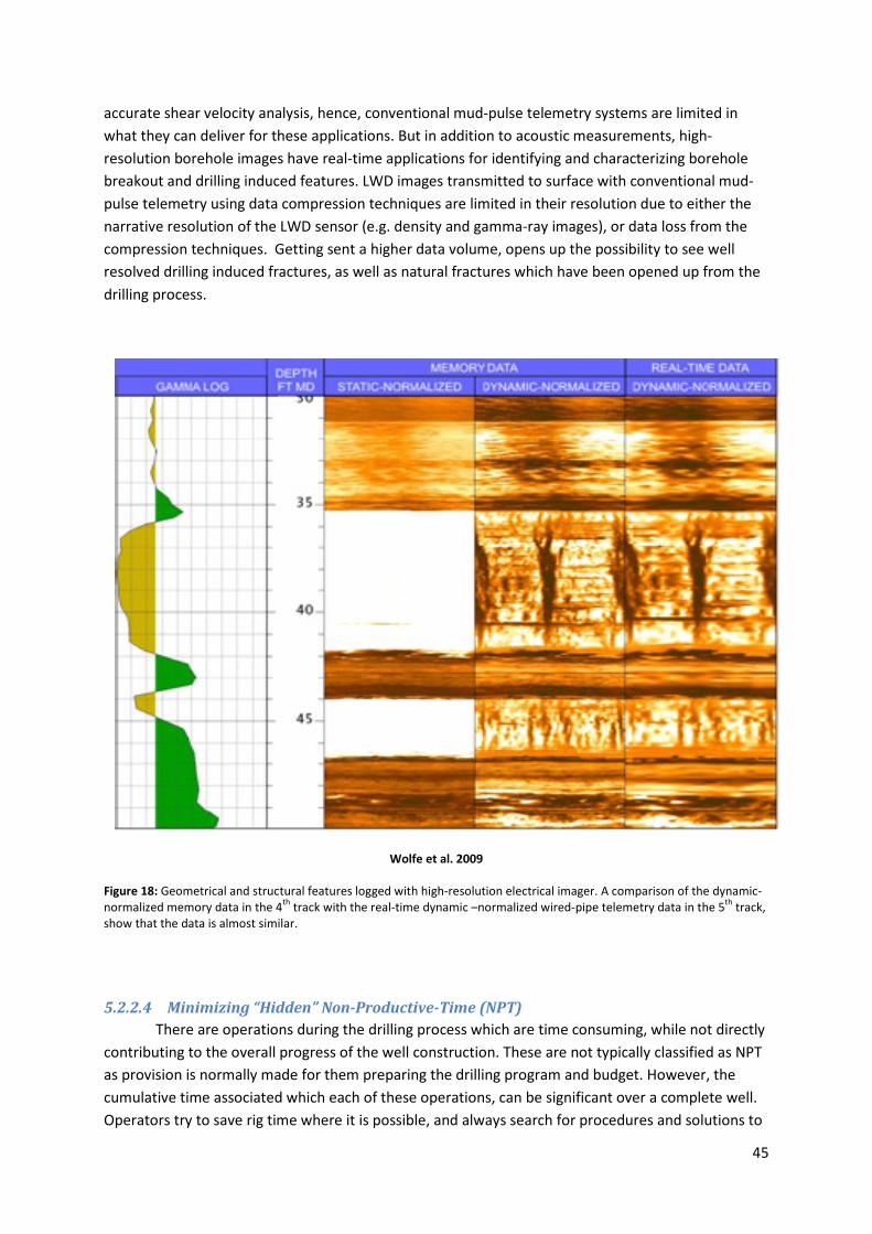
45
accurate shear velocity analysis, hence, conventional mud-pulse telemetry systems are limited in
what they can deliver for these applications. But in addition to acoustic measurements, high-
resolution borehole images have real-time applications for identifying and characterizing borehole
breakout and drilling induced features. LWD images transmitted to surface with conventional mud-
pulse telemetry using data compression techniques are limited in their resolution due to either the
narrative resolution of the LWD sensor (e.g. density and gamma-ray images), or data loss from the
compression techniques. Getting sent a higher data volume, opens up the possibility to see well
resolved drilling induced fractures, as well as natural fractures which have been opened up from the
drilling process.
Wolfe et al. 2009
Figure 18: Geometrical and structural features logged with high-resolution electrical imager. A comparison of the dynamic-normalized memory data in the 4th track with the real-time dynamic –normalized wired-pipe telemetry data in the 5th track, show that the data is almost similar.
5.2.2.4 Minimizing “Hidden” Non-Productive-Time (NPT)
There are operations during the drilling process which are time consuming, while not directly
contributing to the overall progress of the well construction. These are not typically classified as NPT
as provision is normally made for them preparing the drilling program and budget. However, the
cumulative time associated which each of these operations, can be significant over a complete well.
Operators try to save rig time where it is possible, and always search for procedures and solutions to
46
achieve this. Several of the operations performed today using conventional MPT can be either
improved upon or eliminated when utilizing wired-pipe.
5.2.2.4.1 Survey
Using wired-pipe technology, field test show that the actual time saving per orientation survey
could exceed three minutes per successful survey. [10] In the instances where pipe movement or
magnetically interference would corrupt the survey measurement, this would be recognized
immediately. The process of taking a new survey could therefore start instantly. This would in all
instances reduce the overall time spent on the operation, and the time the drillstring is stationary is
kept to a minimum.
5.2.2.4.2 Verification and shallow hole testing
Using wired-pipe, the MPT functionality can be checked by simply observing pulses without
the need to decode, while full system functionality is attained in parallel via the data cable through
the wired-pipe. The downlinking functionality can also be checked instantly. Time spent would
therefore be reduced to the time it takes to establish sufficient circulation and power up the MWD
toolstring.
The need for downloading LWD data at surface would not be immediate if all deliverables are
presented via wired-pipe and fully quality checked (QC) before the tool returns to surface. The time
saved on this would depend on the toolstring. It would still be necessary to connect to the tools to
verify the state of the sensors, especially the resistivity reading, since it cannot be properly verified
on deck. But for the other tools with stand-alone memory (i.e. CoPilot and the Formation Pressure
Tester), it would not be urgent to download the memory.
5.2.2.4.3 Downlink
Sending a downlink would as mention be instantly, there would in no cases be necessary to
neither reduce ROP nor pull off bottom. In most instances, this could also be performed while drilling
using MPT. The real advantage with regards to saving rig-time would be when there is a need for high
data resolution. Then the MPT downlink needs to be sent with reduced ROP or even off-bottom.
5.2.2.4.4 Controlling ROP
There will be no need for drilling with controlled ROP due to poor data density from the LWD
measurements. The limitation of the ROP would therefore only be due to drilling performance or
hole-cleaning issues.
5.2.2.4.5 Formation pressure testing and fluid sampling
Wired-pipe allows continuous communication with the downhole tools during the process of
a pressure test. A real-time analysis of the full pressure profiles would allow optimal parameter
adjustment in real-time, to help assure the best pressure data possible is collected. The data density
acquired from the pressure test would also be similar to memory data quality, and more suitable for
updating pore pressure models, and adjusting the drilling fluid parameters. [2]
During field tests, a reported time saving of seven minutes per formation test was enabled by
the wired-pipe LWD system. [10] It would also open for the possibility to abort a test, if the data
indicates that the tool does not perform as required, e.g. it does not seal against the formation.
47
5.2.2.4.6 Trouble shooting
In the instance where it would be necessary to trouble shoot the downhole tools, the process
of circulating the hole clean and preparing to pull out of hole (POOH) would commence. The
advantage of a wired-pipe system would be the access to more data at a faster rate. The improved
two-way communication allows performing a comprehensive set of tool diagnostics that is only
available when downloading the memory on surface when using MPT.
If managing to determine where the fault lies, a time consuming trip could be avoided. As an
example, the resistivity sensor could stop sending reasonable data. Usually drilling forward without
this sensor would not be permitted, due to the importance of the formations resistivity properties.
The resistivity measurements sent to surface is calculated from four different resistivity receivers
internally in the resistivity tool. If one of these fails, the calculated values sent to surface would be of
no use. It is however possible to calculate the resistivity using only three of the receivers. Direct
communication to the resistivity sub, would clarify instantly if this would be possible.
5.2.2.4.7 Confirmation of network functionality
However, using wired-pipe would in a couple of instances create some extra “hidded” NPT.
During tripping in hole, confirmation of network functionality needs to be tested with a go/no-go
fixture. The frequency of testing would depend on the rig-crews familiarity with the wired-pipe
system.
The connection procedures itself would also be not be as efficient as when using ordinary
drillpipe. A stabbing guide would be required to protect the inductive coils embedded within the
connections in each stand. Training of the rig-crew would be necessary, so the operation would most
likely get more efficient as the get familiarized with the new equipment.
5.2.2.5 Well control operations
With battery powered LWD tools in the BHA, it is also possible to obtain the pressure
measurements during a low-flow killing operation of the well. It would also supply with the different
pressure readings along the string from the signal repeaters, to give a clear view of the well’s
pressure profile.
5.2.2.6 Lost circulation event
With use of LCM, wired-pipe could provide an immediate advantage since it is has no narrowing
of the fluid path and is therefore insensitive to LCM. However, in most cases, the mud-pulser would
be run as part of the BHA as a contingency for lost communication or failure through the wired-pipe.
A trip could therefore still be required if the pulser sub gets blocked. Baker Hughes mud-pulser is also
the power module for the downhole tools. Removing the pulser from the MWD string, would require
another turbine sub to provide the power to the toolstring.
48
5.2.2.7 Pore Pressure Prediction
In order to avoid well control operations from kicks or lost circulation, pore pressure models
can be updated from LWD pressure, acoustic and seismic measurements and used to predict
pressure ahead of the bit for refining drilling parameters before a problem occurs.
Relatively low-bandwidth LWD resistivity measurements have been used with pore pressure
models to predict pore pressure changes with some success. However, it is well known that acoustic
measurements (compressional and shear wave velocities of the formation) are more sensitive to, and
correlate better with formation pressure changes. These measurements require detailed acoustic
waveform analysis to select the right arrival time from different acoustic modes. For conventional
mud-pulse telemetry applications, the bandwidth it too low to send the full waveforms to the surface
for processing and interpretation. Therefore the processing is done automatically in the LWD tools
downhole. However, the processing is quite often subject to picking the wrong arrival times, thus
calculating the wrong formation velocities, without the guidance of an interpreter. This frequently
leads to quite erroneous pore pressure predictions. If the entire set of acoustic waveform data was
streamed to surface, real-time interpretation and QC would be possible. Then the acoustic
processing and resulting pore pressure predictions would be as accurate as possible.
The LWD acoustic measurements are limited in their ability to predict pressure changes
ahead of the bit since they are only capable of measuring changes in the vicinity of the drilling
assembly. Their lower frequency LWD seismic counterparts have the potential to detect pressure
changes ahead of the bit. Although measurement quality, or fidelity, in the drilling environment is
still an issue for these measurements, the potential exists for using them to identify pressure changes
hundreds of meters ahead of the bit. In order to do this though, full waveforms from VSP (Vertical
Seismic Profile) data will be required for analysis at surface. Not only is this measurement useful for
detecting pressure changes, but it will give better prediction of the formation tops, well before they
are reached in the drilling process. However, seismic data-set densities are notoriously large and
would require wired-pipe transmission rates at a minimum to be useful in real-time.
5.2.3 Sensors in the signal repeaters
The network nodes in the signal repeaters offer the unique opportunity to make additional
pressure measurements distributed along the entire length of the drillstring. [19] The systems
additional dynamic insight helps to manage a constant bottomhole pressure as well as drilling at or
under balance. Having the pressure measurement from several places along the string makes it
possible to calculate the rate it changes with and establishing pressure gradients along the wellbore.
The continuous pressure readings distributed at different locations along the drillstring and the
calculated gradients, gives valuable information that can guide decision making in several
applications, such as kick, losses and differential sticking.
To regain well control during a kick, wellsite personnel must circulate out the wellbore influx
and replace the fluid column with denser mud. During this process, constant bottomhole pressure
must be maintained to prevent additional wellbore influx. Constant bottomhole pressure is achieved
by closely operating the choke to keep adequate back pressure and is historically achieved based on
surface measurements. However, with the wired-pipe drillstring, wellsite personnel are offered high-
resolution downhole and annular pressure readings along the string. This additional data is available
49
regardless of flow, providing hydrostatic pressure even at typical kill rates of 10-20 strokes per
minute.
The measurements now commercially available from the signal repeaters are the already
mentioned pressure and temperature readings. There are other measurements on the roadmap to
be developed, such as vibration, strain and caliper. If a strain sensor gets commercially available, this
would measure the tension and compression at its location. This could then be used to accurately
identify sections in the wellbore where the drillstring experience increasing friction or sticking. The
accurate tracking of the reduced tension gradients measured by the drill string will allow to
accurately pin-point the location. [20]
If a large increase of different sensors for use during the drilling operations starts to be
commercially available, it would introduces a challenge for selecting the optimal sensor layout. The
different sensor measurement can be transferred to a variety of useful information during the drilling
process. The sensors could be sensitive to various scenarios, such as kicks and circulations losses.
Most likely there will be limitations to the amount of sensors that will be available to install in the
signal repeaters and a risk analysis of the more likely scenario during drilling operation should be
performed prior to selecting the sensor layout.
5.2.4 Limitations of wired pipe technology
As mentioned earlier, the signal repeaters are the main component to ensure a proper signal
to noise ratio and avoid data loss, and the distance between them would decide the limitation of the
maximum bit rat.
The mechanical properties of the pipe remain unchanged, and the maximum dogleg severity
recommendation for the IntelliServ pipe is the same as to its un-wired counterpart. The wiring do not
affect the tensile strength of the pipe itself, and the armored coax cable is designed to fail at
approximately the strain at which the pipe yields. Depending on the grade of the pipe, this failure
strain may be somewhat after the yield strain of the pipe. However, prior to tensile failure of the
coax cable, some permanent plastic deformation may be sustained by the cable. Wired-pipe has
been deployed in drilling environment with extremely harsh vibrational conditions, included air
hammer drilling and multiple jarring events. It has also been used in drilling operations where it has
been exposed to acid, cement and through-string wireline logging. [15, 18]
The wired-pipe should therefore not be of lower quality then an ordinary drillpipe. The only
new downhole components which then differs from a conventional setup is the interface sub and
signal repeaters. The interface sub is provided by the same service company that provides the
MWD/LWD tools and would therefore be an integrated part of their tools with more or less the same
ratings. For instance, the Baker Hughes Intelli Interface Sub is rated to 150°C and 1725 Bar.
This is the same rating as for the IntelliLinks signal repeaters, and should be sufficient in most
cases. However, an issue to considered is when drilling in HPHT wells. If the downhole environment is
getting close to the maximum rating of 150°C, the locations of the signal repeaters in the drillstring
could become an issue. During drilling, mud circulation is important to avoid over-heating of the
downhole components. Mud pumped down the string would be colder than the downhole
50
environment, and therefore help to lower the temperature and cool the downhole components. The
mud travels quickly down the drillstring, and exits at the bit. It would have a cooling effect from
inside of the string, but as it exits through the bit and gets past the larger outside diameter pipe
which are in the BHA, its traveling speed slows down. A typical BHA configuration could be up to 200
meters if an advanced MWD/LWD service is being run. The cooling effect from the drilling fluid
should still be sufficient to control the temperature of the electronics in the MWD/LWD tools under
normal circulation circumstances. However, if drilling a long horizontal well, the formation
temperature would not change throughout the horizontal section. This means that the signal
repeaters added to the drillstring roughly every 500 meters behind the bit would get poorer and
poorer cooling effect from the mud traveling up through the annulus. Even if sensors closer to the
surface would get a better cooling effect from the mud traveling inside the pipe, they get quite a lot
poorer cooling from the slow traveling mud in the annulus. Hence, the overall cooling effect would
be a less on a signal repeater far away from the bit in a horizontal section.
However, since the signal repeaters have standalone nodes measuring the temperatures
continuously, it would be possible to monitor when the temperature is getting close to the maximum
rating. Monitoring would also be possible during an event where the circulation is below the startup
rate of the MWD power module. During these low flow circulation events, the friction between the
BHA and the wellbore is increased, which consequently generates an additional temperature
increase in the downhole tools. Obviously if the flow rate is low due to a well incident, such as a kill
operation or some sort of lost circulation event, the concern for the health and state of the tools is
not a priority. But there could be several other reasons why the operator wants to continue rotating
without sufficient flow through the tool. An example could be if some of the rig equipment fails and
needs to be changed. Changing a failed component in the pathway of the drilling mud between the
mud pit and the drillstring would not possible with high flow. The operator might still be interested in
rotating the pipe anyway, since keeping the drillstring stationary for too long in the well is not
desirable. If this is done for an extended period of time, the friction heat could then provide enough
heat to damage the electronics inside the tools. The MWD/LWD tools should therefore be
programmed to send up continuous heat measurements as well as the pressure measurements when
the flow is below the start-up threshold for the MWD power module. There are special procedures
that needs to be followed when the temperature of the downhole components gets close to the
maximum rating of 150°C. Circulation has to be staged up slowly to reduce the temperature, without
powering up the MWD/LWD toolstring. The possibility to continuously monitor the downhole tool
temperature would improve this procedure; it would be no doubt about when the temperature
reaches a safe level and the drilling operations could continue.
5.2.5 Reliability
Introducing additional components to a drilling system raises questions about the impact of
the additional complexity on whole system reliability. [2] Since the wired channel operates
independently of the conventional MPT channel, it provides additional telemetry redundancy. The
ability to efficiently switch between the two telemetry methods has been proven on several
commercial jobs, as it has the ability to simultaneously transmit from both channels. Additional
reliability gains are achieved by the ability to troubleshoot any problems within the BHA more
effectively. By having complete access in real-time to the MWD/LWD measuring nodes, you gain the

51
possibility to more systematically troubleshoot and correct problems before or without tripping out
of hole. It also makes it possible to reprogram the MWD/LWD firmware when in hole.
The wired-pipe technology does not have the same proven record of high reliability as MPT.
Continuous improvement is needed to improve reliability, and reduce network downtime. During
field trails, network downtime has been caused by several different reasons, and different
approaches were used to improve the service; [18]
- The network electronics board in the interface sub temporarily ceased to function when
exposed to significant voltage fluctuations from the downhole turbine power source. This
was resolved via firmware programming modifications.
- Movement of the top drive support struts served a data cable carrying the network signal
from the top drive to the logging cabin. Measures were conducted to securing the data cable
better to prevent cable damage. In the future, this connection is planned to be wireless,
which of course would remove the issue with cable damage.
- Regular mis-stabbing of the top drive into new stands caused mechanical damage to
secondary pin shoulder, and inductive coils, at the lower end of the top drive assembly. A
data swivel top drive was used in place of a saver sub and was identified as having a high
potential for being damaged if the driller did not have adequate control over stabbing when
making up pipe. [16] The alignment of the top drive was identified as critical to prevent
damage to the data swivel. An increase in the sensitivity of the driller’s joystick and
familiarize the rig-crew better with handling procedures reduced the possibility for mis-
stabbing.
- Intermittent short circuits where seen in the wired components, coming from failure in the
production process.
Network interruptions like this prevent any significant data transmission from the
amplification joints. As contingency, the networked MWD tools can be programmed to identify any
interruption to the wired-pipe network, and automatically enable the mud-pulser at such times.
One of the major challenges for wired-pipe telemetry applications will be the real-time
processing and display of massive amounts of data in order to allow us to make effective decisions.
That is, the downhole transmission rates will not be the limitation, but our human limitations in
being able to visualize and make decisions on these massive amounts of data.

52
5.3 Additional MWD Transmitters
Below is a short introduction of the type of transmitters used by methods other than mud-
pulse telemetry and wired-pipe. These sections are not exhaustive, and are included for reference
only.
5.3.1 Electromagnetic
Electromagnetic telemetry (EMT) system uses the drillstring as a dipole electrode,
superimposing data words on a low frequency (2-20Hz) source. [1] The receiver antenna typically
consists of two electrodes buried in the ground close to the wellhead, although arrays that are more
complex are possible. Offshore, the situation is more difficult since the receiver array needs to be
placed on the seafloor to detect the signal. Hence, the EM telemetry systems are largely relegated to
the low data-rate, shallow depth, onshore market. [21] EM signals suffer higher attenuation than
mud-pulse signals, and certain types of formations may effectively block transmission. However,
other than a hardwire link to surface, EMT is the most commonly used commercial MWD data
transmission in the compressible fluid environments common in underbalanced drilling applications.
While the EM transmitter has no moving parts, this advantage is somewhat balanced by the high
vibrations generally encountered in underbalanced drilling applications. Communication and
transmission with EMT system can be bi-directional (both uplinking and downlinking are possible).
EM signal amplitude generally attenuates exponentially against depth, although this is highly
dependent on mud and formation resistivity. Modeling will provide information about the expected
signal tendencies, for example the effect of casing on signal amplitudes. The EM transmission is
heavily influenced by many factors, among them the presence of extremely resistive thin beds in the
formation and the distribution of surface
resistivity. These factors are hard to include in the
simulations.
EM Telemetry involves transmitting
through the formation adjacent to the wellbore,
and formation, mud and surface properties
greatly influence the attenuation of the signal. EM
telemetry is a reliable means of transmission in
areas in which formation and mud properties
cooperate. Even in those areas, it is generally only
reliable to depths shallower than 3000 meters. As
with all generalities, there are exceptions, and EM
Telemetry has been achieved to depths greater
than 5000 meters with repeater-less systems.
Decreasing the frequency of the EM signal
results in an increase in signal strength, but it also
decreases the bandwidth of the telemetry system.
Therefore, achievable telemetry bandwidth, the
data-rate, must be balanced against the reach
(maximum achievable depth of the well). Since the conductivity of the formation depends on drilling
V
F M R ece ive r
Insula tion
Baker Hughes et al. 2006
Figure 19: Electromagnetic Telemetry – Alternating current emitted by the MWD tool is detected at surface by two or more receivers
53
location, only the electrical properties of mud can be changed in order to influence the
electromagnetic transmission.
5.3.2 Acoustic Transmission
Acoustic telemetry (Stress-wave Telemetry) uses a downhole sonic telemetry signal that
propagates up the drillstring. [1] Though data-rates are generally relatively high, significant
attenuation of the acoustic signal occurs at drillpipe connections and at any point where the pipe
contacts the borehole wall. Thus, signal repeaters (acoustic amplifiers) are often required in the
drillstring as well depth increases.
The operating frequency band of acoustic telemetry is much higher and broader than for
Mud-Pulse Telemetry and Electromagnetic Telemetry, ranging from 400 Hz to 2 KHz. [22] This range
of frequencies enables acoustic telemetry to operate at significantly higher telemetry rates, even
when employing simple telemetry algorithms.
The successful development of a commercial LWD acoustic telemetry system (LAT) required
resolving two critical hurdles, dynamic attenuation and non-stationary noise. Dynamic variations in
the attenuation occur due to various phenomena associated with drilling processes. Borehole
conditions affect acoustic wave attenuation in a drillpipe. These conditions include characteristics of
the borehole and casing, the deviation of the borehole, physical properties of the drilling mud, and
the extent of contact between pipe and the borehole wall. In addition, attenuation depends on the
characteristics of the drillstring including its mechanical properties, construction, and the type of
mechanical connections between pipes. Any instantaneous variation in one or more of the properties
changes the attenuation.
Non-Stationary noise typically results from a combination of processes occurring downhole
including types of drill bits disintegrating the formation, weight on bit, type of formation, the RPM of
the drillstring, contact between tubing and formation and casing, and type of mud motor used. In
addition, surface equipment like mud pumps, rotary tables, or top drives generate significant noise.
Normal rig operations and environment-related noise add to the overall noise.
The very basic telemetry system would comprise of a downhole transmitter to package and
transmit data and a surface receiver to receive and decode the data. Any downhole transmitter could
be damaged by shocks generated during the drilling process. However, an easy method of migrating
drilling shock related damage is to position the transmitter as far away from the drill bit as possible.
The preferred position for most other LWD sensors and tools is as close to the bit as possible in the
BHA. Therefore, the downhole transmitter can be designed to be above all LWD tools. This concept
results in a couple of advantages for the system. The noise generated at the bit would be attenuated
and distorted by the LWD tools before it reached the transmitter. The transmitter would also be
located at the top of the BHA and would therefore be connected directly to the drill collars, which
are extremely good conveyers of acoustic signals.
Additional acoustic isolation from the drilling noise is obtained by positioning an acoustic
attenuator between the drill bit and the transmitter. The attenuator is designed specifically to
attenuate in-band noise in the acoustic telemetry frequency band of operation. This device

54
attenuates noise as it enters the communication channel. It also helps attenuate signals generated by
the transmitter itself before they reflect from the drill bit and reenter the channel where they can
cause inter-symbol interference. The transmitter interfaces with the MWD/LWD data bus to access
tool information.
An optional repeater could be positioned between the downhole transmitter and the surface
receiver. It would act as a signal booster to increase the depth of operation and the rate at which
data would be transmitted. The repeater has similar design specifications to the downhole
transmitter and functions similarly.
The drillstring could travel as much as 30-40 meters in one stand run. This variation could be
completely avoided by fixing the receiver below the top drive or above the Kelly and below the
swivel. This positioning of the transceiver enables the transceiver to move with the drillstring and
lead to minimal interference with rig operations. The transceivers transfers, via a wireless link,
digitized acoustic signals to a data processing and storage computer located in a safe area. The
processing computer is used as a platform to interface with all components of the LAT system, to
decode the acquired acoustic signals, and display, evaluate, and store this material as needed.

55
6 Drilling Processes and Automation
The pressure in the wellbore, the annular pressure, is a combination of the hydrostatic pressure
of the fluid and cuttings in the well, as well as applied pressure from circulation or at surface.
Formations being drilled through
contain fluid, such as water, oil or
gas, which is being held within
pores of the formation. The
pressure the formation fluid is
held within the pores is referred
to as pore pressure. Fracture
pressure is the pressure required
to fracture the formation.
During drilling it is usually
desirable to keep the annular
pressure above the pore pressure
and bellow the fracture pressure.
As the drilling process gets more
complicated, for instance in
depleted reservoirs or deepwater
wells, the margins between pore-
and fracture pressure becomes
smaller. Controlling the pressure
profile, or the annular pressure,
of the well, is therefore of great
importance.
Automation is the
introduction of control systems
and information technology to
reduce the physical and/or
mental workload of human operators in charge of a running process. [23] It is a step beyond
mechanization, which assists operators by replacing human power by mechanical. In the drilling
industry, automation has been relatively low, but automation of various aspects of the drilling
process such as ensuring mud properties, pipe handling, precise borehole pressure control (used for
instance in Managed-Pressure-Drilling), and automation of the different drilling operations, such as
tripping, directional drilling and pump start up, are now either commercially available or on the verge
of becoming available.
Malloy et al. 2009
Figure 20: Drilling Windows for Conventional Drilling Operations, Managed Pressure Drilling Operations and Underbalanced Drilling Operations
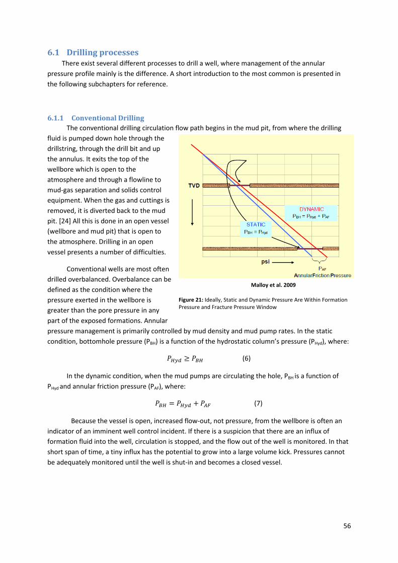
56
6.1 Drilling processes
There exist several different processes to drill a well, where management of the annular
pressure profile mainly is the difference. A short introduction to the most common is presented in
the following subchapters for reference.
6.1.1 Conventional Drilling
The conventional drilling circulation flow path begins in the mud pit, from where the drilling
fluid is pumped down hole through the
drillstring, through the drill bit and up
the annulus. It exits the top of the
wellbore which is open to the
atmosphere and through a flowline to
mud-gas separation and solids control
equipment. When the gas and cuttings is
removed, it is diverted back to the mud
pit. [24] All this is done in an open vessel
(wellbore and mud pit) that is open to
the atmosphere. Drilling in an open
vessel presents a number of difficulties.
Conventional wells are most often
drilled overbalanced. Overbalance can be
defined as the condition where the
pressure exerted in the wellbore is
greater than the pore pressure in any
part of the exposed formations. Annular
pressure management is primarily controlled by mud density and mud pump rates. In the static
condition, bottomhole pressure (PBH) is a function of the hydrostatic column’s pressure (PHyd), where:
789: ≥ 7<8 (6)
In the dynamic condition, when the mud pumps are circulating the hole, PBH is a function of
PHyd and annular friction pressure (PAF), where:
7<8 = 789: + 7>? (7)
Because the vessel is open, increased flow-out, not pressure, from the wellbore is often an
indicator of an imminent well control incident. If there is a suspicion that there are an influx of
formation fluid into the well, circulation is stopped, and the flow out of the well is monitored. In that
short span of time, a tiny influx has the potential to grow into a large volume kick. Pressures cannot
be adequately monitored until the well is shut-in and becomes a closed vessel.
Malloy et al. 2009
Figure 21: Ideally, Static and Dynamic Pressure Are Within Formation Pressure and Fracture Pressure Window
57
6.1.2 Underbalanced Drilling
In general terms, underbalanced drilling operations and techniques are primarily utilized to
enhance reservoir productivity. [24] Underbalanced Drilling (UBD) is a drilling activity employing
appropriate equipment and controls where the pressure exerted by the fluid in the wellbore is
intentionally less than the pore pressure in any part of the exposed formations. The intent is to bring
formation fluids to surface, where PHyd is less than PBH.
In addition to improved rate of penetration, the chief objectives of underbalanced drilling are
to protect, characterize, and preserve the reservoir while drilling so that well potential is not
compromised. To accomplish this objective, influxes are encouraged. The influxes are allowed to
traverse up the hole and are suitably controlled by surface containment devices.
With the capability to deploy a complete MWD/LWD toolstring into underbalanced drilling
environments while maintaining full data transmission via wired-pipe telemetry, the application of
UBD techniques to complex directional/horizontal wells can be expanded dramatically.
6.1.3 Managed Pressure Drilling
Managed Pressure Drilling (MPD) is an application driven technology designed to migrate
drilling hazards such as lost circulation, stuck pipe, wellbore instability and well control incidents. To
drill these problem wells, various techniques can be employed to manage the annular hydraulic
pressure profile of the exposed wellbore. Proactive control of the equivalent mud weight within the
drilling window tends to allow the option to set casing seats at depths greater than can be achieved
conventionally through overbalanced drilling and reduces non-productive time.
MPD utilizes technology to drill with a planned and pre-described pressure profile using
techniques and equipment beyond those available conventionally, while UBD is simply drilling below
pore pressure intentionally. Where UBD typically seek formation influx into the well bore, MPD
makes every attempt to avoid influx. Any flow incidental to MPD operations is to be contained using
an appropriate process, in similar fashion to conventional drilling. Compared to conventional drilling
practices, containment of influxes is generally better controlled with MPD due to advances in
techniques associated with the equipment employed.
The vast majority of MPD is practiced while drilling in a closed vessel utilizing a Rotating
Control Device with at least one drillstring Non-Return Valve, and a Drilling Choke Manifold. Manual
controlled and microprocessor controlled chokes are available depending on the application.
Presuming that the wellbore is capable of pressure containment by sealing the wellbore, pressure
throughout the wellbore can be better monitored at the surface on real-time basis. In a closed
system, changes in pressure are seen immediately. By more precisely controlling the annular
wellbore profiles, detection of influxes and losses are virtually instantaneous. The safety of rig
personnel and equipment during everyday drilling operations is enhanced.
In some challenging drilling environments wellbore stability pressures and pore pressure may
be in very close proximity to one another. In some wells the lines will cross, where the pore pressure
will be less than the well bore stability pressure. Under those conditions, precise control of the
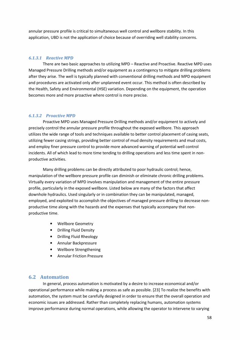
58
annular pressure profile is critical to simultaneous well control and wellbore stability. In this
application, UBD is not the application of choice because of overriding well stability concerns.
6.1.3.1 Reactive MPD
There are two basic approaches to utilizing MPD – Reactive and Proactive. Reactive MPD uses
Managed Pressure Drilling methods and/or equipment as a contingency to mitigate drilling problems
after they arise. The well is typically planned with conventional drilling methods and MPD equipment
and procedures are activated only after unplanned event occur. This method is often described by
the Health, Safety and Environmental (HSE) variation. Depending on the equipment, the operation
becomes more and more proactive where control is more precise.
6.1.3.2 Proactive MPD
Proactive MPD uses Managed Pressure Drilling methods and/or equipment to actively and
precisely control the annular pressure profile throughout the exposed wellbore. This approach
utilizes the wide range of tools and techniques available to better control placement of casing seats,
utilizing fewer casing strings, providing better control of mud density requirements and mud costs,
and employ finer pressure control to provide more advanced warning of potential well control
incidents. All of which lead to more time tending to drilling operations and less time spent in non-
productive activities.
Many drilling problems can be directly attributed to poor hydraulic control; hence,
manipulation of the wellbore pressure profile can diminish or eliminate chronic drilling problems.
Virtually every variation of MPD involves manipulation and management of the entire pressure
profile, particularly in the exposed wellbore. Listed below are many of the factors that affect
downhole hydraulics. Used singularly or in combination they can be manipulated, managed,
employed, and exploited to accomplish the objectives of managed pressure drilling to decrease non-
productive time along with the hazards and the expenses that typically accompany that non-
productive time.
• Wellbore Geometry
• Drilling Fluid Density
• Drilling Fluid Rheology
• Annular Backpressure
• Wellbore Strengthening
• Annular Friction Pressure
6.2 Automation
In general, process automation is motivated by a desire to increase economical and/or
operational performance while making a process as safe as possible. [23] To realize the benefits with
automation, the system must be carefully designed in order to ensure that the overall operation and
economic issues are addressed. Rather than completely replacing humans, automation systems
improve performance during normal operations, while allowing the operator to intervene to varying
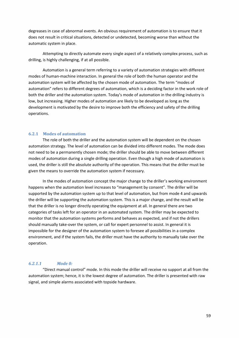
59
degreases in case of abnormal events. An obvious requirement of automation is to ensure that it
does not result in critical situations, detected or undetected, becoming worse than without the
automatic system in place.
Attempting to directly automate every single aspect of a relatively complex process, such as
drilling, is highly challenging, if at all possible.
Automation is a general term referring to a variety of automation strategies with different
modes of human-machine interaction. In general the role of both the human operator and the
automation system will be affected by the chosen mode of automation. The term “modes of
automation” refers to different degrees of automation, which is a deciding factor in the work role of
both the driller and the automation system. Today’s mode of automation in the drilling industry is
low, but increasing. Higher modes of automation are likely to be developed as long as the
development is motivated by the desire to improve both the efficiency and safety of the drilling
operations.
6.2.1 Modes of automation
The role of both the driller and the automation system will be dependent on the chosen
automation strategy. The level of automation can be divided into different modes. The mode does
not need to be a permanently chosen mode; the driller should be able to move between different
modes of automation during a single drilling operation. Even though a high mode of automation is
used, the driller is still the absolute authority of the operation. This means that the driller must be
given the means to override the automation system if necessary.
In the modes of automation concept the major change to the driller’s working environment
happens when the automation level increases to “management by consent”. The driller will be
supported by the automation system up to that level of automation, but from mode 4 and upwards
the driller will be supporting the automation system. This is a major change, and the result will be
that the driller is no longer directly operating the equipment at all. In general there are two
categories of tasks left for an operator in an automated system. The driller may be expected to
monitor that the automation systems performs and behaves as expected, and if not the drillers
should manually take-over the system, or call for expert personnel to assist. In general it is
impossible for the designer of the automation system to foresee all possibilities in a complex
environment, and if the system fails, the driller must have the authority to manually take over the
operation.
6.2.1.1 Mode 0:
“Direct manual control” mode. In this mode the driller will receive no support at all from the
automation system; hence, it is the lowest degree of automation. The driller is presented with raw
signal, and simple alarms associated with topside hardware.
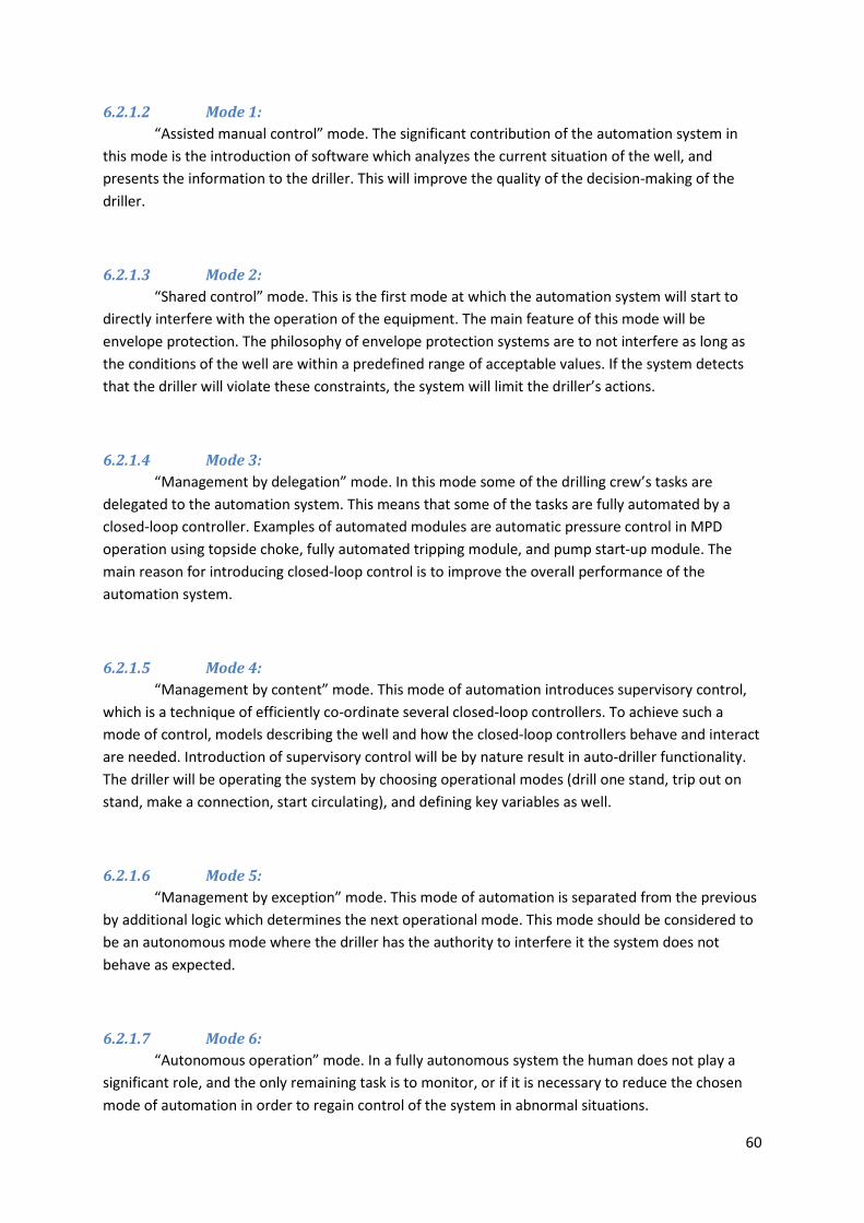
60
6.2.1.2 Mode 1:
“Assisted manual control” mode. The significant contribution of the automation system in
this mode is the introduction of software which analyzes the current situation of the well, and
presents the information to the driller. This will improve the quality of the decision-making of the
driller.
6.2.1.3 Mode 2:
“Shared control” mode. This is the first mode at which the automation system will start to
directly interfere with the operation of the equipment. The main feature of this mode will be
envelope protection. The philosophy of envelope protection systems are to not interfere as long as
the conditions of the well are within a predefined range of acceptable values. If the system detects
that the driller will violate these constraints, the system will limit the driller’s actions.
6.2.1.4 Mode 3:
“Management by delegation” mode. In this mode some of the drilling crew’s tasks are
delegated to the automation system. This means that some of the tasks are fully automated by a
closed-loop controller. Examples of automated modules are automatic pressure control in MPD
operation using topside choke, fully automated tripping module, and pump start-up module. The
main reason for introducing closed-loop control is to improve the overall performance of the
automation system.
6.2.1.5 Mode 4:
“Management by content” mode. This mode of automation introduces supervisory control,
which is a technique of efficiently co-ordinate several closed-loop controllers. To achieve such a
mode of control, models describing the well and how the closed-loop controllers behave and interact
are needed. Introduction of supervisory control will be by nature result in auto-driller functionality.
The driller will be operating the system by choosing operational modes (drill one stand, trip out on
stand, make a connection, start circulating), and defining key variables as well.
6.2.1.6 Mode 5:
“Management by exception” mode. This mode of automation is separated from the previous
by additional logic which determines the next operational mode. This mode should be considered to
be an autonomous mode where the driller has the authority to interfere it the system does not
behave as expected.
6.2.1.7 Mode 6:
“Autonomous operation” mode. In a fully autonomous system the human does not play a
significant role, and the only remaining task is to monitor, or if it is necessary to reduce the chosen
mode of automation in order to regain control of the system in abnormal situations.
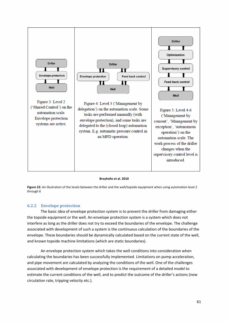
61
Breyholtz et al. 2010
Figure 22: An illustration of the levels between the driller and the well/topside equipment when using automation level 2 through 6
6.2.2 Envelope protection
The basic idea of envelope protection system is to prevent the driller from damaging either
the topside equipment or the well. An envelope protection system is a system which does not
interfere as long as the driller does not try to exceed the boundaries of the envelope. The challenge
associated with development of such a system is the continuous calculation of the boundaries of the
envelope. These boundaries should be dynamically calculated based on the current state of the well,
and known topside machine limitations (which are static boundaries).
An envelope protection system which takes the well conditions into consideration when
calculating the boundaries has been successfully implemented. Limitations on pump acceleration,
and pipe movement are calculated by analyzing the conditions of the well. One of the challenges
associated with development of envelope protection is the requirement of a detailed model to
estimate the current conditions of the well, and to predict the outcome of the driller’s actions (new
circulation rate, tripping velocity etc.).
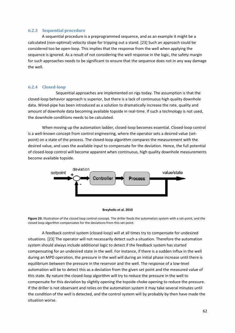
62
6.2.3 Sequential procedure
A sequential procedure is a preprogrammed sequence, and as an example it might be a
calculated (non-optimal) velocity slope for tripping out a stand. [23] Such an approach could be
considered too be open-loop. This implies that the response from the well when applying the
sequence is ignored. As a result of not considering the well response in the logic, the safety margin
for such approaches needs to be significant to ensure that the sequence does not in any way damage
the well.
6.2.4 Closed-loop
Sequential approaches are implemented on rigs today. The assumption is that the
closed-loop behavior approach is superior, but there is a lack of continuous high quality downhole
data. Wired-pipe has been introduced as a solution to dramatically increase the rate, quality and
amount of downhole data becoming available topside in real-time. If such a technology is not used,
the downhole conditions needs to be calculated.
When moving up the automation ladder, closed-loop becomes essential. Closed-loop control
is a well-known concept from control engineering, where the operator sets a desired value (set-
point) on a state of the process. The closed-loop algorithm compares the measurement with the
desired value, and uses the available input to compensate for the deviation. Hence, the full potential
of closed-loop control will become apparent when continuous, high quality downhole measurements
become available topside.
Breyholtz et al. 2010
Figure 23: Illustration of the closed loop control concept. The driller feeds the automation system with a set-point, and the closed loop algorithm compensates for the deviations from this set-point.
A feedback control system (closed-loop) will at all times try to compensate for undesired
situations. [23] The operator will not necessarily detect such a situation. Therefore the automation
system should always include additional logic to detect if the feedback system has started
compensating for an undesired state in the well. For instance, if there is a sudden influx in the well
during an MPD operation, the pressure in the well will during an initial phase increase until there is
equilibrium between the pressure in the reservoir and the well. The response of a low-level
automation will be to detect this as a deviation from the given set point and the measured value of
this state. By nature the closed-loop algorithm will try to reduce the pressure in the well to
compensate for this deviation by slightly opening the topside choke opening to reduce the pressure.
If the driller is not observant and relies on the automation system it may take several minutes until
the condition of the well is detected, and the control system will by probably by then have made the
situation worse.

63
To fully utilized the higher levels of automation to improve the performance of the overall
drilling operations, high quality reliable downhole data will be the key to allow the drilling operation
to operate closer to the boundaries of the operation while taking safety issues into consideration. It
is likely that if high quality downhole data through wired-pipe (or competitive technology) becomes
available at a large number of wells/operations, the demand for closed-loop control will grow
rapidly.
6.2.5 Challenges with automation
Monitoring of drilling operations is a task where a human may not excel routinely for long
periods of time, unless non-optimal, abnormal or unwanted situations are indicated by an alarm
system. [23] Diagnostic and warning systems (expert systems) have been proposed as an appropriate
strategy to increase the performance of human operators who have a monitoring role. Expert
systems are often designed to give the operator a warning/alarm when the system fails, but for some
critical situations this may be too late. An efficient strategy should be to analyze the current
situations and try to predict if a failure is likely to occur in the immediate future. The higher the level
of automation is, the more crucial the communication about the automation systems mode and
intentions become.
Unfortunately it is only after the automation system has misbehaved that the driller can
detect its misbehavior. Since a manual take-over of the drilling process is likely to be motivated by an
abnormal situation, and it requires both skill and experience to recognize both the reason for the
abnormal situation and the correct counter-action to bring the well/system back to normal
operational conditions. The time available to do both tasks are most likely limited. Detection systems
and decision support systems may be of assistance, but in general the behavior of the driller will be
based on experience. Drillers with experience from manual operations would most likely have a more
intuitive understanding of when a manual take-over is needed. If a highly automated environment
becomes the norm, then the manually skills of the drillers will most likely decline, and that may
reduce the probability of the driller safely handling a manual take-over.
There are possible issues related to trust when discussing expert systems.[23] In general such
systems have prevented several possible dangerous situations, but if these systems are extremely
reliable, there is a possibility that the drilling crew will rely on them at all times, and when a rare
failure occurs, the drilling crew may not detect the failure due to overreliance on the automation
system. An opposite problem is expert systems which produce false alarms at a high frequency. In
such case, the drilling crew is likely to mistrust the alarms, and in extreme cases ignore or even
switch of the alarms completely. Sensor failures and sensors drifting may result in expert systems
raising false alarms regarding downhole conditions.
6.2.6 Control algorithms and models
There are algorithm developed which represents a possibility to coordinate RPM, hook
position, and circulation rate such that the WOB can be controlled, and an optimal ROP is achieved.
WOB poses significant control challenges, but if it is controlled it can be kept closer to an optimum,
and an optimal ROP can be obtained. [23]

64
6.2.6.1 Supervisory control
The main task of a supervisory control level is to coordinate all the low-level feedback
controllers and calculate their set-points. [23] There are different control strategies for this level, one
of them being known as Model Predictive Control (MPC). MPC is the only advanced control
technique that has a significant and widespread impact on industrial processes control; hence the
possibility should be there to introduce it in the drilling process as well. The main reason for its
success are its ability to handle multivariable control problems naturally, take account of actuator
limitations, and allow the process to operate closer to its constraints. MPC is a form of control in
which the current control action is obtained by solving, at each sampling instant, a finite-horizon
open-loop optimal control problem, using the current state of the plant as the initial state. The either
linear or nonlinear models used in the MPC algorithm can be obtained through various methods,
such as experimental step response models or mathematical models.
The MPC algorithm represents a possibility to coordinate the surface parameters to achieve
an optimal ROP. If sufficient reliable downhole data are available, there is also a possibility to include
these in the process.
The necessary inputs to the supervisory control level are constraints due to operational
bounds and machine limitations. The machine limitations are most likely constant during the whole
operation, but the constraints related to downhole conditions should be updated if new information
becomes available. In addition to constraints, the set-points for the crucial variables have to be
provided, such that the output variables, e.g. pressure, hook position, RPM, is brought to their
desired values.
Information about the downhole conditions would be available even with slow sampled
downhole data. Hence, the possibility would be there to update the MPC algorithm with this
information. Including the limitations of the downhole toolstring as a part of the algorithm would be
an efficient measure to avoid downhole tool failures. A more accurate visualization of the downhole
parameters would be provided by a wired-pipe telemetry system, which again would result in a more
accurate process control system. This would especially be a major advantage to try to avoid
operating the downhole tools outside their limitations.
6.2.6.2 Hydraulic models
With the introduction of wired-pipe telemetry, more information from downhole to surface
would be available. However, this does not replace the need for hydraulics models. [25] On the
contrary, more measurements from the process will increase the range of applications for hydraulic
models. There is a large potential of applying models for forward predictions related to e.g. well
control, MPD and extended reach drilling. Also, models are needed to provide information on
variables that are not being measured directly. Models may also replace sensors that drift or fall out
and in general improve the methodologies of filtering measured data.

65
7 Integrating the MWD/LWD Service Into the Drilling Control System
During normal drilling practice and with the systems that are in place now, the MWD systems
are not integrated into the drilling control system. The data from the MWD/LWD tools is received in
the service companies’ surface software system, and distributed from this to the monitoring
computers rig site and onshore. The data then has to be processed and interpreted by the dedicated
persons watching them, and real-time decisions have to be made from this.
The data format is raw data and it requires manual interpretation and action in order to use the
data in controlling the drilling process. [3] Since the data is not fed into any drilling process control
system, it is a manual, open-loop control. Using conventional mud-pulse telemetry, the time from
when the actual downhole measurements were taken until the process parameters can be adjusted
may be several minutes at best. Due to this, the use of drilling data in the time window where they
have its highest value potential is limited.
7.1 Directional Drilling
Trying to fully automate such a complex process as directional drilling would be a hard task to
overcome. Several uncertainties exist prior to drilling the well, and changes to the planned well
trajectory could be necessary during the drilling process. Especially in the lower sections of the well,
and when geosteering, the well path could be dependent on formation tops and reservoir properties.
Also it would be impossible to predict the performance of the steering unit itself, and several
adjustments to its steering parameters would be required as drilling commences.
Some advanced steering unit has the possibility to adjust some of the parameters internally.
When drilling in tangent sections, the desired inclination could be programmed into the tool, and it
would use an integrated inclination sensor to maintain this inclination. This function could also be
used when building or dropping the angle of the well. The desired inclination is programmed into the
tool, together with the force the tool should use to reach it. When it target inclination is reached, the
tool is set-up to maintain this until told otherwise. However, this is just possible with the inclination,
and the azimuthal direction of the well needs to be monitored and adjusted manually.
This feature of the steering unit controls the direction of the well in the same way as a control
system would. Hence, it would serve no purpose to integrate this function into the drilling control
system.
All the other parameters in the steering unit are changed by decisions from the directional
driller. There should be no reason that an introduction of wired-pipe, which results in more
downhole data and instantaneously communication with the downhole tool, would change that.
Monitoring the wellpath and performance of the steering unit is done by highly trained directional
drillers, which in turn advises the driller if any adjustments have to be done to the surface
parameters. Introduction of any high mode of automation with respect to directional drilling
therefore seems very unlikely.
66
7.1.1 LWD tools used for reservoir navigation
As mentioned will the formation properties measurements from the LWD logs determine if
any change to the planned well trajectory are necessary, or at least confirm the formation prognosis.
It could be thought that these measurements could be exploited more efficiently, and maybe
integrated in some sort of drilling automation system.
However, due to the complexity of the LWD measurements and the nature of the
measurement, data processing and control is needed on surface prior to using the data. [3] For
instance, there is also an interpretation aspect to a resistivity image that still requires human
interaction. Increasing the data density with the use of wired-pipe telemetry will not change the
need for interpretation. The resistivity image data or other LWD data is therefore not feasible for
direct input into drilling process control software.
In exploration wells there would not be much information available about the formations
along the wellpath. Models generated by interpretation of seismic data could be the only
information available of the properties and structure of the different formations. Hence, little is
known about the formation and what to expect from the LWD measurements. This is not the case in
highly explored fields, where several wells are drilled already. The response from the LWD tools
would, in most instances, indicate the familiar formation boundaries and could even explain the
location in a given formation. When this is the case, it could be possible to integrate the LWD
measurements into a low mode of automation. For instance if the plan is to drill the well only into
the top of the reservoir formation, the drilling control system could be programmed to stop drilling
when the measurements indicates that the reservoir has been reached.
The usefulness of such a function integrated into the drilling control system would be limited.
Drilling a well the conventional way, the geologist would, in cooperation with the MWD/LWD
engineer, keep a close eye on these measurements throughout the drilling, notifying the driller to
stop drilling when the target depth is reached. As already mentioned, a computer based system
would not be able to interpret these data properly anyway.
7.2 Optimizing drilling parameters
Better utilization of the measured downhole drilling parameters would be possible if the
amount of collected data increased, for instance by the use of wired-pipe. Deviations would be
detected as early as possible, and measures taken to correct them. These measures could be
integrated into a Drilling Control System.
It would probably also be possible to do this using slow sampled data from MPT or similar, but
events like vibrations could have major impacts on the decoding performance. This could in some
instances result in few, or none updates of the downhole parameters, and the efficiency of the
measures will not be monitored. Nor would the automation system receive any new data for its
calculations.

67
7.2.1 Vibrations
When severe levels of vibrations are measured, a reduction of these would be necessary.
Flowcharts are developed with the actions to take in these instances. [26] These explain the different
changes to the surface parameters that could be required depending on the type of vibrations
experienced. Hence, the process of reduction or elimination of the vibrations could be automated by
the drilling control system. Having continues downhole updates would also ensure that the results of
the changes is seen quickly, or if further measures needs to be taken. Under some circumstances the
vibrations caused by the drilling operations would have to be ignored, for instance due to high angle
of the well or trying to break through rough formations. Even though a high mode of automation
would be possible in most cases, the driller would require the option to change to a lower mode
during these phases of the drilling operation.
7.2.2 Drilling performance
Integrating the downhole measurements into the drilling control system as an addition to the
surface parameters would improve on the efficiency of the drilling performance. With the downhole
WOB and torque values available, more information would be available about the forces at the bit.
The impact of altering the surface parameters would become evident, and the correct measures
could be taken to improve the drilling performance.
Measuring the bend of the string could also be an early indication on the development of high
local doglegs. Depending on the drilling operation, it could be necessary to react on a sudden change
in the bending moment as fast as possible. Algorithms could be developed to automatically detect
and warn rig-site personnel when such an event is taking place.
7.3 Monitoring annular pressure
The Equivalent Circulation Density (ECD) is the gradient value calculated from the downhole
pressure measurement and reflects the effective density exerted by a circulating fluid against the
formation. [5] This value is monitored closely, and any significant change to its trend is reacted upon.
It is expected that the ECD trend is increasing as the wellbore gets deeper, i.e. pressure increases,
due to higher friction loss and more cuttings accumulate in the annulus. If the ECD value gets close to
the calculated fracture gradient, measures will be implemented. This could be reduction of the flow-
rate or hold back on the ROP to reduce the amount of generated cuttings. The deviations from the
established trends usually takes place over a period of time, and the decision to which measure to
make is often stated in the pre-well drilling program.
Any change that affects the drilling progress is not desirable and especially reduction of ROP
has to be approved by the client. The approach could therefore be different from client to client, or
even depending on their representative on the rig. For instance, if the ECD value is higher than
desired due to accumulated cuttings, a reduction of ROP would be a possibility. Another approach
would be to drill down the stand as fast as possible, and instead spend time circulating the hole clean
in-between connections.

68
To improve the drilling progress, and reducing the time spent, integrating the MWD pressure
measurements directly into a drilling control system could be a solution. If it is predetermined which
approach to take if such an instance develop, suitable algorithms could be developed and coded into
the automation software to adjust the drilling parameters as required. This feature would be possible
in the highest modes of automation. It would most likely also be possible with slow sampled
downhole data, since there is no need for continuous measurements, only a well-developed trend.
7.3.1 Well control
As mentioned earlier, most kill operations are conducted at flow rates below which the MWD
tools are able to transmit mud-pulses. Hence, the use of downhole pressure gauges mounted in the
BHA cannot be used. Having available continuous downhole pressure measurements, irrespective of
the flow condition, via wired-pipe will enable checking validity of calculations, monitoring execution
of the well control operation and ultimately reduce the uncertainty for safer, more precise and
effective outcome.
However, any variation to established procedures must be carefully considered. Rig site
personnel seldom have to perform kill operations, and an influx to the well will create a stressful
situation among those involved. Hence, whichever well control method is adopted, it is important
that documented procedures are fully understood and followed by the rig personnel to avoid gross
errors. But the opportunity to enhance current practice using wired-pipe throughout the kill
operation does exist.
7.4 MWD measurements integrated into a MPD control system
Managed-Pressure-Drilling with automatic control of the back-pressure choke was the first
application where real-time downhole drilling data was used for direct closed-loop control of the
downhole drilling process. [3] The emergence of this technology is likely due to the possibility to
obtain real-time data of the downhole pressure by means of a hydraulic model calibrated against
slow-sampled downhole data.
In an automated MPD system, the automation of the choke manifold is performed by a control
system consisting of two main parts; a hydraulic model that predicts the downhole pressure in real-
time, and a feedback control algorithm which automates the choke manifold to maintain the desired
downhole pressure.
Thus, it would be possible to integrate the MWD measurements transmitted through Mud-
Pulse Telemetry in an automated MPD process. If utilizing a wired-pipe telemetry system which
would give frequent updates of the downhole parameters, integration of the real-time into a model
could also be used to control the back-pressure in the MPD operation. To obtain a robust solution
with the respect to possible failures in the drillstring telemetry, a real-time hydraulic model could
estimate the downhole pressure every second for feedback to the surface back-pressure control
system. Due to the higher data sampling due to the wired-pipe, the model could be calibrated
against the downhole measurements every 2 seconds. This would ensure extremely high accuracy in
the downhole pressure estimate at all times during normal drilling. However, if a kick is detected, the

69
control system should switch to using
the high-speed telemetry pressures
directly. The hydraulic model would
have significantly reduced accuracy in
case of high compressibility (two-
phase) flow.
7.4.1 Optimizing the annular
pressure
The combination of continuous
annular pressure readings integrated in
an automated MPD process could
improve the well control in the entire
drilling operation. As mentioned, it has
already been successfully implemented
in the drilling process.
Another example of this
application could be a tripping
operation. During tripping, the pressure
in the well will be affected by the
movement of the pipe, and pressure
fluctuations are induced. [23] The main
primary goal of a tripping operation is
to keep the annular pressure within its
boundaries, while the second one would be to complete the tripping operation as fast as possible.
If a self-optimizing approach is used, the optimization level will calculate a constant semi-
optimal set-point, and rely on the lower level feedback controllers to maintain the pressure at this
level. A low-level feedback controllers will likely not prevent the annular pressure deviating from the
set-point to some degree, a safety-margin is needed to prevent the pressure from exceeding the
drilling window.
An optimized tripping operation could be achieved by the following example;
If a true optimal set-point is continuously calculated, an optimal pressure set-point curve could
be calculated, which will allow the pressure set-point to be slightly increased while tripping out, and
oppositely reduced while tripping in. Calculating these curves would allow for faster tripping without
violating the pressure boundaries.
Optimizing the tripping operation in a conventional drilling process would also be possible
using wired-pipe. The effect on the drilling control system would not be as complicated as for MPD,
since it would only be the tripping speed of the surface operations that would affect the annular
pressure, no back pressure would be applied at surface.
Hovda et al. 2008
Figure 24: Schematic diagram of an Automated MPD system utilizing distributed downhole sensors for real-time model calibration.

70
7.5 Surface sensors
The MWD service could consist in a variety of surface sensors to be able to detect and extract
the signal from the downhole tools. These sensors are connected directly to the MWD software, and
only used to ensure proper data retrieval. The rig provides its own measurements of the same
surface parameters, with a secondary measurement performed by the mud-logging service company.
The set-up of surface sensors will depend on the telemetry method used. If wired-pipe
telemetry is used, without running MPT as a contingency, the pressure sensors to detect the mud-
pulses as well as the sensors used for noise cancelation would be redundant. In such an instance,
only the radiation monitoring would be required at surface.
7.5.1 Radiation detector
The radiation monitoring is the only surface measurement that is only performed by the MWD
engineer, and the action taken will depend on his reaction. The fact that this is a surface
measurement increases the importance of a quick response. In a drilling situation, there are usually
people in the logging unit at all times, which should react if the radiation alarm is triggered. But in a
very unfortunate situation, this might not be the case. However, if something happens with the
radioactive source installed in the LWD sub, the measurements would give no reasonable values. The
time from when this happens until the contamination reaches surface, would be a while, of course
dependent on the flow-rate and annular volume. It is very likely that someone recognizes the bad
LWD measurements, since these data is being monitored by several people, both offshore and
onshore. Hence, troubleshooting of the LWD toolstring would in the vast majority of cases already
have commenced, and the engineer would be in the logging unit to react on the triggered alarm.
However, this is a measurement that it should be easy to connect to a drilling control system.
The required response would be to shut off the pumps to further investigate the cause of the alarm.
In the majority of operations, the main concern would be to limit the radiation contamination of the
mud-system and the rig. Hence, the measurement could be integrating into the highest mode of
automation.
71
8 Discussion & Conclusion The discussion of the different aspects and features of the different technologies are done more
thoroughly in its associated subchapters.
8.1 Telemetry methods
As mentioned several times, the vast majority of wells are drilled using mud-pulse telemetry.
This technology has a proven record of its performance, and the indications are that this is going to
be the preferred technology also in the future, both for Conventional and Managed Pressure Drilling
processes. However, MPT would not be the preferred option in an Underbalanced Drilling Process,
and techniques such as Electromagnetic Telemetry is used. The focus in this paper has been on
mainly on MPT and Wired-pipe.
8.1.1 Mud-pulse telemetry vs. Wired-pipe telemetry
The wired-pipe telemetry performance is, in theory, without any doubt a better technique
with regards to downhole communication. Hence, a question arises of why this technology is not
being utilized more often.
8.1.1.1 Data-rates and noise interference
Using MPT, the raw data-rate (the symbol rate in the telemetry channel) and the effective
data-rate (the raw data rate adjusted for data compression and transmission overhead), can be quite
different. A compartment of data rates between MWD service companies will therefore be quite
difficult due to the variations in between them. For instance, one company’s 12 bit word transmitted
at 12 bits per second may give the same data density on surface as another company’s 6 bit word
transmitted at 6 bit per second. Nor does a comparison of data-rate give any indication if competitor
companies will have the same performance in decoding that data-rate. The ability to decode the data
at surface will be of equal or higher importance. Data rates typically achieved with mud-pulse
telemetry systems range from 3 to 40 bits per second. [1, 27]
In addition, the performance of MPT are affected by noise introduction by mud pumps, signal
loss due to depth, fluid properties, and/or fluid flow rate since flow is required for transmission. Both
signal noise and attenuation could cause decoding errors, which results in missing or misinterpreted
measurements. The wired-pipe is not affected by any of these factors, and the data-rate is only
determined by the spacing of the signal repeaters.
With wired-pipe the bottleneck in data acquisition would be in the surface processing
equipment, or internally in the LWD tools. In MPT it would be the transmission rate or the data
recovery. The internal sampling rate in LWD sensors could sometimes limits the data delivery rate,
and in other instances the measurement principle is the limiting factor. [3] Some downhole
measurements are based on a certain number of readings to get a statistical base to compute a value
that in turn is transmitted to surface. Other downhole sensors are designed to only take readings
often enough to transmit up values every 30 to 60 seconds. With wired-pipe, sensor redesign,
72
internal communication upgrades and software upgrades are required to remove many of these
limitations and enable use of a larger part of the available bandwidth.
8.1.1.2 Monitoring annular pressure
Using wired-pipe to continuously measure the annular pressure would without any doubt
increase the possibility of better real-time monitoring and well control, especially during flow-off
events such as connections. However, during a connection procedure, the driller’s attention would
mainly be on adding the new stand of drillpipe to the string. Even more so using wired-pipe, due to
the slightly more advanced connection procedures. Hence, to fully be able to benefit from these
measurements, an automation system that would not require the driller’s attention would have to
be installed. This could then be updated with the real-time measurements, in contrary to using the
single post-connection value provided with the survey using MPT.
It could also be worth mentioning that a good flow-off measurement would require static
flow conditions in the well. In instances where the procedure is to perform the survey prior to
connection, for instance due to poor hole condition, these measurements could be of no value. The
usual procedure is to reduce the flow to a rate where the power module stops generating power,
and increase it back up again to the required flow rate. Hence, some frictional pressure would be
included to the annular pressure, which would give a higher measurement than the actual
hydrostatic pressure in the well during the connections. Using these data to calculate the back-
pressure during a MPD system would therefore also be wrong. The theoretical calculated back-
pressure would be too little, which in the worst case could lead to a fluid influx into the well. It would
therefore not be possible to include flow-off pressure from MPT into an automated MPD process in
such instances. Using wired-pipe telemetry with continuous pressure monitoring would of course
resolve that.
8.1.1.3 Well control
As mentioned several times, data transmission for telemetry systems such as MPT is only
possible during fluid flow, meaning that the status of the downhole environment is unknown while
pumps are off, or at reduced flow such as during a well kill operation. [19] The procedures to handle
such well incident are developed to meet those conditions. Even though better monitoring of the
annular pressures would be available with wired-pipe, a great amount of care should be taken
changing the pattern of behavior. This are well established procedures, and even if the rig-crew have
regular drills on how to perform them, they rarely, if ever, have executed the procedure in a real
event. Recover the well barriers should in all instances be the main goal in the event of a well control
operation; other concerns for the well should come in second line. More accessible downhole data
could equally well increase the likelihood of making the operation more confusing or complicated, as
to be an advantage for the driller.
8.1.1.4 Cost and reliability
To run a reliable wired-pipe service, some modifications have to be performed on the drilling
equipment on the rig, and the rig-crew must get sufficient training handling the new equipment.

73
Hence, there is a cost related to changing technology. Also, while running the wired-pipe technology,
the MPT system serves as a backup if the wired-pipe system malfunctions or fails. This redundancy
ensures minimum data requirements are continually met and avoids NPT for equipment
troubleshooting or repair. [27] Since the pulser can be an integrated part of the sub that generates
power (e.g. Baker Hughes’ BCPM) to the toolstring, the MPT system will be an integrated part of the
MWD/LWD string.
Until wired-pipe can show to the same proven record of high reliability as MPT in a wide range
of operating environments, it is very likely that the MWD/LWD toolstring will remain unchanged.
However, if the wired-pipe is found to be reliable, future MWD/LWD tools could have very little
embedded electronics. Commands and control could instead take place from surface computers via
the network. This fundamental architecture change would enable significant reduction in tool cost
and complexity, which would improve toolstring reliability and reducing the non-productive time
associated with tool failures.
Running wired-pipe will also require a minimum of two dedicated field specialists on the rig.
[15] On offshore rigs, especially on the smaller sub-submersibles and jack-up rigs, lack of bed space is
a usual problem. Therefore, the trend is to try to remote control more of the drilling process from
onshore control centers, to reduce the amount of people on the rig. This will however not be an
important issue if the deployment of wired-pipe is proved to give a great advantage drilling new
wells. However, until the technology gets a foothold, this concern will not speak to its advantage.
8.1.1.5 Cooperation between different service companies
The wired-pipe delivered by NOV is an open architecture which allows any MWD/LWD service
company that manufactures an interface sub to connect to the networked drillpipe. The MWD/LWD
toolstring is still provided by the same service company as before, functioning the same way. Hence,
no combination of different MWD/LWD tools from different providers would be possible in the
wired-pipe set-up either.
In some rare instances, different service companies have their tools in the same BHA. This
could be done to compare the measurements provided by the two different MWD/LWD companies.
When this is done using MPT, one of the service companies have to run their tool in silent mode, i.e.
measuring the data and saving them to the memory, not transmitting data to surface. It would not be
possible to use two mud-pulsers in the same mud channel, since they would just disturb each other’s
signal.
This option is not possible with wired-pipe. The tool run in silent mode would have to be
placed outside the other service company’s toolstring, i.e. above the interface sub. As mentioned
earlier, all the components above the interface sub must be wired, something an MWD/LWD tool is
not. An alternation to allow this could be possible, but not very likely.
8.2 Integration into a Drilling Control System
The problem with integration the MWD/LWD measurements into a drilling control system
would be that the likelihood of retrieving bad values due to poor decoding is too large. Poorly
74
decoded measurements would give false measurements, which would trigger false alarms from the
control system. If then a true alarm is raised, the probability of the drilling crew trusting the alarm
system decreases with the number of false alarms they have experienced. If the amount of reliable
downhole data was increased, for instance by wired-pipe telemetry, the integration process would
be simpler.
Another important issue in monitoring is the communication between the automation system
and the driller. It is important that the state of the automation system is communicated to the driller.
The driller needs to be informed about the systems intentions in order to understand its behavior. In
order to further improve the quality of the automation system its behavior should be predictable. If
both the mode/state of the system and its future actions (prediction) are communicated to the
driller it will prevent the driller from misunderstanding whether a critical situation has been
detected, and if it is being handled or not. To ensure that the quality of the expert system is high, the
driller needs to monitor the data which are sent to the system. As the level of automation increases,
there is a risk that the automation process could cause a degradation of the rig-crews experience
with the drilling process.
The involvement of several different companies, with different technologies, is necessary to
integrate the downhole measurements into drilling control system. The drilling control system would
in most instances be the responsibility of the drilling contractor, while the downhole measurements
would be provided from the MWD service company. If wired-pipe telemetry is used, this would also
involve another company to provide the wired-pipe components and surface system. Hence, there
would be a lot of different software’s and systems that have to interact. The input of data to the
control system could be through WITSML or rig-specific data communication software. This will by all
means not be impossible, but will complicate the drilling process. Clear guidelines must be in place
for this to operate in a safe manner.
However, the advantages would be major if integration was achieved. Algorithms which for
instance automatically detect when a kick, loss, pack off or differential sticking event take place could
be developed. If a proper process control system is developed, for instance using a MPC controller,
better control of the drilling process would be achieved. It would give the possibility adjust the
surface parameters and verify that is has the desired effect on the downhole drilling parameters. This
way the drilling process would be optimized and damage on surface equipment and downhole tools
would be avoided.
A further exploitation of automation during a MPD processes, for better control of the annular
pressure, would be a large improvement to the safety of the drilling operations and probably lead to
a reduction of time and cost induced by drilling a well.
8.3 Relations to health, safety and environment
Safety is always the primary goal of any drilling operation and this will always remain the case.
The high-speed wired-pipe provides the opportunity to enhance the safety of operations from a
number of perspectives. The significance of this will increase as drilling activity progresses into ever
more challenging environments.
75
8.3.1 Downhole Annular and Formation Pressure Monitoring
One of the primary benefits with wired-pipe is the opportunity to increase the safety of
drilling operations. The ability to continuously transmit data at high-speed (interrupted only while
making drillstring connections), completely independent of drilling fluid properties and circulation
rate, allows monitoring of a wide array of well status information.
The most immediate safety benefit is via monitoring of downhole annular pressure from
sensors already available within most MWD systems. Earlier kick detection and more precisely
controlled bleed-off procedures will deliver a higher degree of certainty in preventing escalation of
well control incidents as well as improving drilling efficiencies. Similarly, the ability to monitor
downhole swab and surge pressure while tripping will simultaneously optimize tripping speed for
enhanced safety and efficiency.
8.3.2 Reducing manual handling
Over the years the amount of manual handling on rigfloor has been severely reduced. This
has been a major enhancement to the safety. However, building the MWD/LWD toolstring still
require quite a lot of manual handling due to the complexity of the connections. Any automation of
this operation is not very likely. The MWD engineer must still verify that all the connections are
made-up properly, and that there is no contamination on the internal communication line used by
the tools.
76
9 Reference
[1] A Primer on MWD Telemetry, Baker Hughes, 2006
[2] Hernandez, M., MacNeill, D., Reeves, M., - IntelliServ Incorporated; Kirkwood, A., Lemke, S.,
Ruszka, R., Zaeper, R., - Baker Hughes Inteq, High-Speed Wired Drillstring Telemetry Network Delivers
Increased Safety, Efficiency, Reliability and Productivity to the Drilling Industry, SPE 113157, 2008
[3] Hovda, S., Wolter, H., Kaasa, G.O., Ølberg, T.S., StatoilHydro ASA, Potential of Ultra High-Speed
Drill String Telemetry in Future Improvements of the Drilling Process Control, IACD/SPE 115196, 2008
[4] Wolfe, C., SPE, Morris, S., and Baule, A., SPE, Baker Hughes Inc., Enhanced Real-Time Wellbore
Stability Monitoring Using High-Definition Imaging With Wired Pipe Telemetry, SPE/IADC 119808,
2009
[5]MWD; ECD; Directional Drilling; Survey. Available from: <http://www.glossary.oilfield.slb.com>,
2012
[6]Drilling Services; Logging While Drilling. Available from: <http://www.bakerhughes.com/products-
and-services/drilling/drilling-services>, 2012
[7] BHI_Guidelines_solar_activity, Baker Hughes, 2012
[8] TesTrak Formation Pressure Testing. Available from: http://www.bakerhughes.com/products-
and-services/evaluation/logging-while-drilling/testrak-formation-pressure-testing , 2012
[9] 04_Components_BCPM.ppt, Baker Hughes, 2007
[10] Manning, M.J., MacPherson, J., Peveto, C., Taylor, D.E. and Baksh, N., Baker Hughes, Wired Pipe-
Enabled Logging While Drilling Applications, IPTC 12504, 2008
[11] Eriksen, L.E., Høgskolesenteret i Rogaland, Lecture notes; The well bore trajectory – position
calculations, 1993
[13] Formation_Pressure_Test_Procedure_with_TesTrak, Baker Hughes, 2012
[12] Klotz, C., Kaniappan, A., Thorsen, A.K., SPE, Nathan, E., SPE, Baker Hughes Inteq, Jahangir, M.,
SPE, Lie, L., StatoilHydro, A New Mud Pulse Telemetry System Reduces Risks When Drilling Complex
Extended Reach Wells, IADC/SPE 115203, 2008
[14] Measurement while drilling. Available from:
<http://en.wikipedia.org/wiki/Measurement_while_drilling>, 2012
[15] The IntelliServ Network. Available from:
<http://www.nov.com/Downhole/Telemetry_Drill_Strings>, 2012
[16] Ali, T.H., SPE, Sas, M., Hood, J.A., Lemke, S.R., and Srinivasan, A., SPE, INTEQ; McKay, J., Fereday,
K.S., Mondragon, C., Townsend, S.C., and Edwards, S.T., SPE, BP America Inc., Hernandez, M., SPE,
77
Reeves, M., SPE, IntelliServ Inc., High Speed Telemetry Drill Pipe Network Optimizes Drilling Dynamics
and Wellbore Placement, IADC/SPE 112636, 2008
[17] IntelliServ Network Interface Sub, Baker Hughes, 2009
[18] Reeves, M., SPE, IntelliServ Inc; Macpherson, J., SPE, and Zaeper, R., SPE, Baker Hughes Inteq;
Bert, D., SPE, BP America Inc; Shursen, J., HG Intl; Armagost, K., SPE, BP America Inc; and Pixton, D.,
and Hernandez, M., SPE, InelliServ Inc., High Speed Drillstring Telemetry Network Enables New Real-
Time Drilling and Measurement Technologies, IADC/SPE 99134, 2006
[19] Veeningen, D., NOV IntelliServ, Along-String Pressure Evaluation Enabled by Broadband
Networked Drillstring Provide Safety, Efficiency Gains, OTC 22239, 2011
[20] Fossgard, E., Nygaard, G.H., Vefring, E.H., SPE, IRIS Petroleum, Method for Optimal Placement of
Sensors in a Wired Pipe Drillstring, IADC/SPE 108345, 2007
[21] Schnitger, J., Macpherson, J., Baker Hughes, Signal Attenuation for Electromagnetic Telemetry
Systems, SPE/IADC 118772, 2009
[22] Shah, V., and Gardner, W., Halliburton Energy Services, Johnson, D.H., and Sinanovic, S., Rice
University, Design Considerations for a New High Data Rate LWD Acoustic Telemetry System, SPE
88636, 2004
[23] Breyholtz, Ø., IRIS, Nikolaou, M., University of Houston, Drilling Automation: Presenting a
framework for Automated Operations, 2010
[24]Malloy, K.P., SPE, Stress Engineering Services, Stone, C.R., SPE, and Medley, Jr., G.H., SPE, Signa
Engineering, Hannegan, D., SPE, Weatherford International, Coker, O., SPE, ConocoPhillips, Reitsma,
SPE, @Balance, Santos, H., SPE, and Kinder, J., SPE, Secure Drilling, Eck-Olsen, J., SPE, StatoilHydro,
McCaskill, J., SPE, Expro Group, May, J., SPE, Smith Services, Smith, K., SPE Sonneman, P., SPE,
Chevron Energy Technology, Managed Pressure Drilling: What It Is and What It Is Not, IADC/SPE
122281, 2009
[25] Gravdal, J.E., SPE, and Lorentzen, R.J., SPE, IRIS, and Time, R.W., SPE, UiS, Wired Drill Pipe
Telemetry Enables Real-Time Evaluation of Kick During Managed Pressure Drilling, SPE 132989, 2010
[26] VSS Flowcharts, Baker Hughes, 2007
[27] S. Allen, SPE, and C. McCartney, SPE, Occidental Petroleum, M. Hernandez, SPE, and M. Reeves,
SPE, NOV IntelliServ; A. Baksh and D. MacFarlane, Baker Hughes, Step-Change Improvements with
Wired-Pipe Telemetry, IACD/SPE 119570, 2009
[28] Advantage Combinatorial, Baker Hughes, 2008
[29] Directional Drilling, Baker Hughes, 2012


![norges teknisk-naturvitenskapelige universitetAsymptotic methods on the other hand, such as Geometrical Optics, Physical Optics and the Geometric Theory of Di˙raction [24], typically](https://img.pdfslide.us/doc/110x75/5f52738e538eb32ca3036339/norges-teknisk-naturvitenskapelige-universitet-asymptotic-methods-on-the-other-hand.jpg)