Embed Size (px)
Citation preview

ISIJ International, Vol. 61 (2021), No. 1
© 2021 ISIJ1
ISIJ International, Vol. 61 (2021), No. 1, pp. 1–10
https://doi.org/10.2355/isijinternational.ISIJINT-2020-421
* Corresponding author: E-mail: [email protected]
© 2021 The Iron and Steel Institute of Japan. This is an open access article under the terms of the Creative Commons Attribution-NonCommercial-NoDerivs license (https://creativecommons.org/licenses/by-nc-nd/4.0/).CCBYNCND
1. Introduction
With the rapid growth of the production and consumption of plastic products in recent years, the demand for plastic die steel is increasing. Plastic die steel not only has higher requirements for wear resistance, hardness, and welding performance but also has perfect corrosion resistance.1) Sulfur mainly exists in the form of inclusions in steel, such inclusions are disposed to micro-cracks and pitting pits in plastic die steel, which seriously affects their service life.2–4) Therefore, to control the formation of sulfide inclusions, and improve the cleanliness of steel, the sulfur content in steel must be decreased as much as possible.
At present, electroslag remelting (ESR) process has been widely used for producing high-quality plastic die steel due to its advantages, such as excellent solidification structure and strong ability to remove inclusions, especially remove
Desulfurization Behavior of Low-sulfur Plastic Die Steel during ESR Process under Different Atmospheres
Congpeng KANG,1) Fubin LIU,1,2) Xin GENG,1,2) Zhouhua JIANG,1,2)* Kui CHEN,1) Junzhe GAO1) and Ruidong AN1)
1) School of Metallurgy, Northeastern University, Shenyang, 110819 China.2) State Key Laboratory of Rolling and Automation, Northeastern University, Shenyang, 110819 China.
(Received on July 20, 2020; accepted on September 4, 2020; J-STAGE Advance published date: October 28, 2020)
Experimental investigation and kinetics model ware carried out to study the effect of the atmosphere on the desulfurization of low-sulfur plastic die steel during the electroslag remelting process. 55Cr17Mo1VN plastic die steel was applied as the electrode and remelted with two different kinds of atmospheres using a laboratory-scale ESR furnace. It was found that the sulfur content of 50 ppm in the electrode decreased to 8–12 ppm in the air atmosphere, while reduced to 9–14 ppm in a protective atmosphere. The desulfur-ization rates were 82% and 78%, respectively. Correspondingly, the sulfur content of 0.12% in initial slag increased to 0.125% and 0.15%. The coupled desulfurization kinetics model was established, the oxygen activity (aO) and sulfur distribution coefficient (Ls) are taken into consideration, and they change with the remelting time during the calculation. The results show that the calculated values are in good agreement with the experimental values. The desulfurization effect at the electrode tip is significantly better than the positions where the droplet passes through the slag layer and the slag pool/molten pool interface. The Ls and comprehensive mass transfer coefficient of sulfur ( )S*k decrease with the remelting time, while the aO at each reaction position increases. Compared with the protective atmosphere, Ls and kS* have larger values during the air atmosphere ESR process, but the aO value is equal. Under the different atmospheres, the most types of inclusions in the steel are MnS, and the refining atmosphere has no significant effect on the types of inclusions.
KEY WORDS: electroslag remelting; kinetics; mass transfer coefficient; atmosphere; desulfurization; low-sulfur plastic die steel.
sulfide inclusions in steel.5–12) A multitude of paper points out that desulfurization in the ESR refining process is affected by many factors, such as slag composition, electrode com-position, remelting rate, power supply parameters, remelting atmosphere, and so on. Eissa et al.13) studied the influence of the physical properties of slag on desulfurization, and the desulfurization is the result of the combined slag-metal reaction and slag-gas reaction during the ESR process. Liu et al.14) found that increasing the remelting current increased sulfur content in the ingot. Cao et al.15) found that the desul-furization ability was improved under single power two-circuits ESR process. Besides, Shi et al.16) systematically described the relationship between deoxidation and desulfur-ization during ESR process. Ban-Ya, Bronson, and Pierre et al.17,18) all pointed out that increasing the content of CaO and CaF2 in the slag and increasing the temperature is beneficial to desulfurization. In addition, Wang et al.19–21) established a transient three-dimensional coupled mathematical model to study the desulfurization behavior and predicted the sulfur
ISIJ International, Advance Publication by J-StageISIJ International, Advance Publication by J-STAGEISIJ International, Advance Publication by J-StageISIJ International, J-Stage Advanced Publication, DOI: http://dx.doi.org/10.2355/isijinternational.ISIJINT-2015-@@@
ISIJ International, Advance Publication by J-STAGE, DOI: 10.2355/isijinternational.ISIJINT-2020-421
ISIJ International, Vol. 61 (2021), No. 1
© 2021 ISIJ 2
content during the ESR process. Besides, Mattar et al.22) demonstrated that the nitrogen alloying process delayed the removal of sulfur during the ESR process.
Besides, the atmosphere of the ESR process also has a crucial effect on desulfurization. Dong et al.23) used electrode with sulfur content of 0.01% and found that the desulfurization rate was reduced due to the weakened gas-phase desulfurization under the protective atmosphere. Hou et al.24) established the desulfurization model of the protective ESR process by using 1Cr21Ni5Ti steel with a sulfur content of 0.035% and explained the desulfurization mechanism. However, Previous studies on the influence of ESR on desulfurization were mostly carried out in the case of high sulfur content in the electrode, few studies have reported the desulfurization behavior of low-sulfur steel in the ESR process under different atmospheres. Moreover, in order to make the calculation more accurate, the Ls (sulfur distribution coefficient) and aO (oxygen activity) should be regarded as variables in the ESR process. Therefore, it is necessary to further improve the accuracy and rationality of the desulfurization model during the ESR process.
In the current works, experimental and model research on the desulfurization behavior of low-sulfur plastic die steel during the ESR process in different atmospheres were con-ducted. The experiments were performed in an air atmosphere and a protective atmosphere. Then, the desulfurization kinet-ics models in two kinds of atmospheres were established, which provide a theoretical basis to further reduce the sulfur content in the steel and improve the purity of steel grades.
2. Experimental
2.1. Experimental ProcedureThe experiments were carried out in a 50 kg ESR furnace
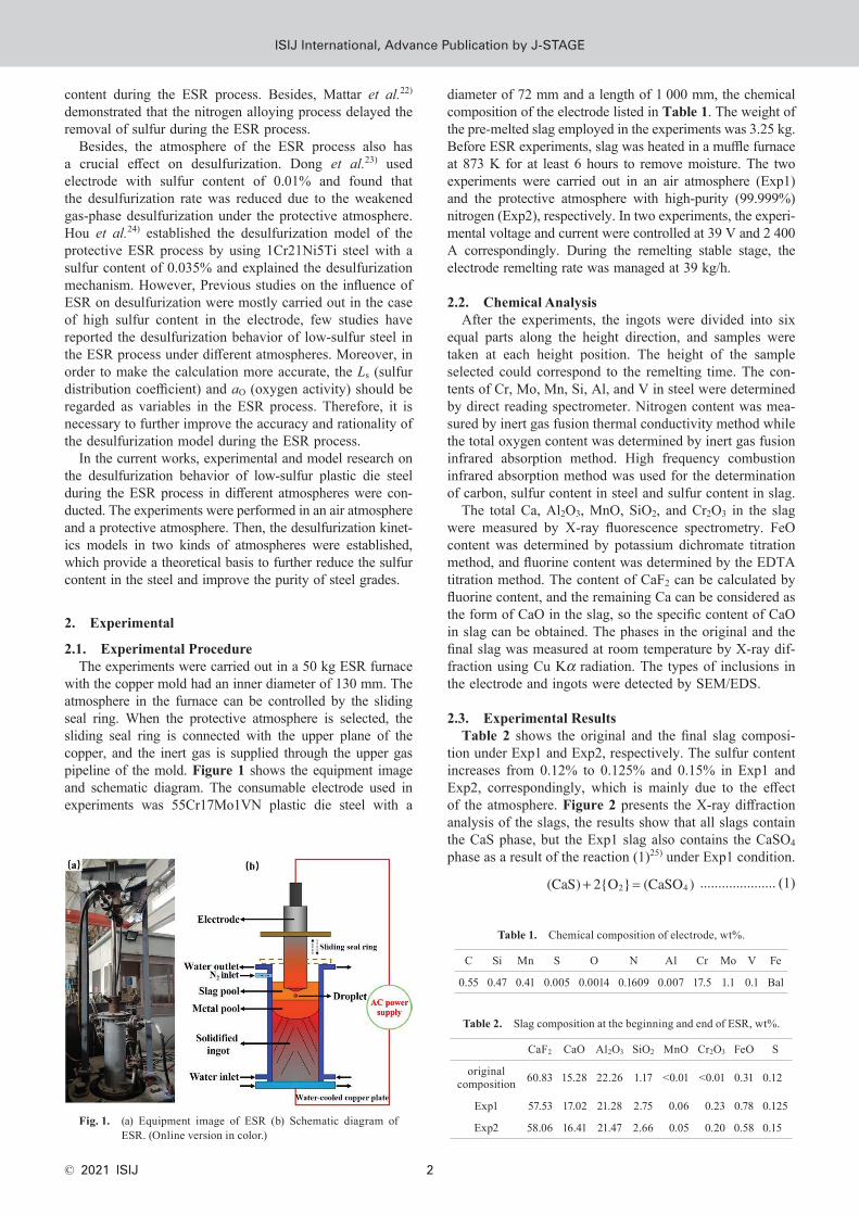
with the copper mold had an inner diameter of 130 mm. The atmosphere in the furnace can be controlled by the sliding seal ring. When the protective atmosphere is selected, the sliding seal ring is connected with the upper plane of the copper, and the inert gas is supplied through the upper gas pipeline of the mold. Figure 1 shows the equipment image and schematic diagram. The consumable electrode used in experiments was 55Cr17Mo1VN plastic die steel with a
diameter of 72 mm and a length of 1 000 mm, the chemical composition of the electrode listed in Table 1. The weight of the pre-melted slag employed in the experiments was 3.25 kg. Before ESR experiments, slag was heated in a muffle furnace at 873 K for at least 6 hours to remove moisture. The two experiments were carried out in an air atmosphere (Exp1) and the protective atmosphere with high-purity (99.999%) nitrogen (Exp2), respectively. In two experiments, the experi-mental voltage and current were controlled at 39 V and 2 400 A correspondingly. During the remelting stable stage, the electrode remelting rate was managed at 39 kg/h.
2.2. Chemical AnalysisAfter the experiments, the ingots were divided into six
equal parts along the height direction, and samples were taken at each height position. The height of the sample selected could correspond to the remelting time. The con-tents of Cr, Mo, Mn, Si, Al, and V in steel were determined by direct reading spectrometer. Nitrogen content was mea-sured by inert gas fusion thermal conductivity method while the total oxygen content was determined by inert gas fusion infrared absorption method. High frequency combustion infrared absorption method was used for the determination of carbon, sulfur content in steel and sulfur content in slag.
The total Ca, Al2O3, MnO, SiO2, and Cr2O3 in the slag were measured by X-ray fluorescence spectrometry. FeO content was determined by potassium dichromate titration method, and fluorine content was determined by the EDTA titration method. The content of CaF2 can be calculated by fluorine content, and the remaining Ca can be considered as the form of CaO in the slag, so the specific content of CaO in slag can be obtained. The phases in the original and the final slag was measured at room temperature by X-ray dif-fraction using Cu Kα radiation. The types of inclusions in the electrode and ingots were detected by SEM/EDS.
2.3. Experimental ResultsTable 2 shows the original and the final slag composi-
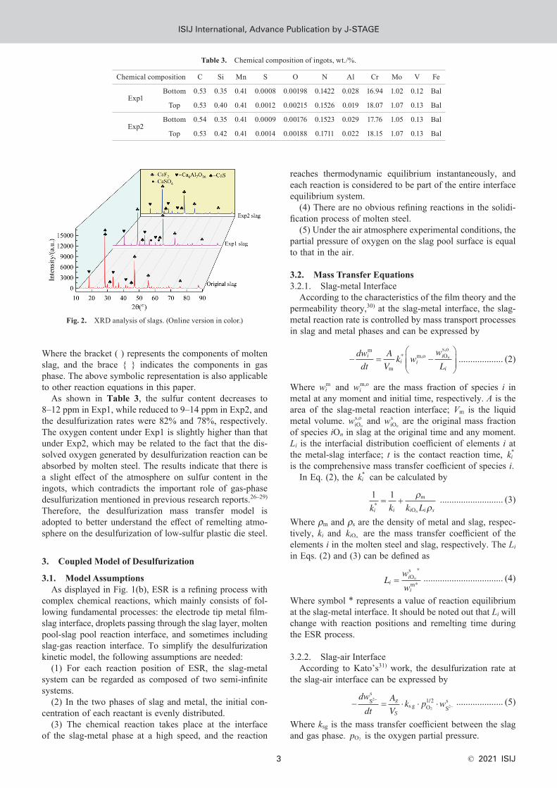
tion under Exp1 and Exp2, respectively. The sulfur content increases from 0.12% to 0.125% and 0.15% in Exp1 and Exp2, correspondingly, which is mainly due to the effect of the atmosphere. Figure 2 presents the X-ray diffraction analysis of the slags, the results show that all slags contain the CaS phase, but the Exp1 slag also contains the CaSO4 phase as a result of the reaction (1)25) under Exp1 condition.
(CaS) 2{O } (CaSO )2 4+ = ..................... (1)
Fig. 1. (a) Equipment image of ESR (b) Schematic diagram of ESR. (Online version in color.)
Table 1. Chemical composition of electrode, wt%.
C Si Mn S O N Al Cr Mo V Fe
0.55 0.47 0.41 0.005 0.0014 0.1609 0.007 17.5 1.1 0.1 Bal
Table 2. Slag composition at the beginning and end of ESR, wt%.
CaF2 CaO Al2O3 SiO2 MnO Cr2O3 FeO S
original composition 60.83 15.28 22.26 1.17 <0.01 <0.01 0.31 0.12
Exp1 57.53 17.02 21.28 2.75 0.06 0.23 0.78 0.125
Exp2 58.06 16.41 21.47 2.66 0.05 0.20 0.58 0.15
ISIJ International, Advance Publication by J-StageISIJ International, Advance Publication by J-STAGE
ISIJ International, Vol. 61 (2021), No. 1
© 2021 ISIJ3
Where the bracket ( ) represents the components of molten slag, and the brace { } indicates the components in gas phase. The above symbolic representation is also applicable to other reaction equations in this paper.
As shown in Table 3, the sulfur content decreases to 8–12 ppm in Exp1, while reduced to 9–14 ppm in Exp2, and the desulfurization rates were 82% and 78%, respectively. The oxygen content under Exp1 is slightly higher than that under Exp2, which may be related to the fact that the dis-solved oxygen generated by desulfurization reaction can be absorbed by molten steel. The results indicate that there is a slight effect of the atmosphere on sulfur content in the ingots, which contradicts the important role of gas-phase desulfurization mentioned in previous research reports.26–29) Therefore, the desulfurization mass transfer model is adopted to better understand the effect of remelting atmo-sphere on the desulfurization of low-sulfur plastic die steel.
3. Coupled Model of Desulfurization
3.1. Model AssumptionsAs displayed in Fig. 1(b), ESR is a refining process with
complex chemical reactions, which mainly consists of fol-lowing fundamental processes: the electrode tip metal film-slag interface, droplets passing through the slag layer, molten pool-slag pool reaction interface, and sometimes including slag-gas reaction interface. To simplify the desulfurization kinetic model, the following assumptions are needed:
(1) For each reaction position of ESR, the slag-metal system can be regarded as composed of two semi-infinite systems.
(2) In the two phases of slag and metal, the initial con-centration of each reactant is evenly distributed.
(3) The chemical reaction takes place at the interface of the slag-metal phase at a high speed, and the reaction
reaches thermodynamic equilibrium instantaneously, and each reaction is considered to be part of the entire interface equilibrium system.
(4) There are no obvious refining reactions in the solidi-fication process of molten steel.
(5) Under the air atmosphere experimental conditions, the partial pressure of oxygen on the slag pool surface is equal to that in the air.
3.2. Mass Transfer Equations3.2.1. Slag-metal Interface
According to the characteristics of the film theory and the permeability theory,30) at the slag-metal interface, the slag-metal reaction rate is controlled by mass transport processes in slag and metal phases and can be expressed by
� � ��
���
�
���
dw
Vk w
wii i
i n
m
m
* m,o Os,o
dt
A
Li ................... (2)
Where wim and wi
m,o are the mass fraction of species i in metal at any moment and initial time, respectively. A is the area of the slag-metal reaction interface; Vm is the liquid metal volume. w
niOs,o and w
niOs are the original mass fraction
of species iOn in slag at the original time and any moment. Li is the interfacial distribution coefficient of elements i at the metal-slag interface; t is the contact reaction time, ki* is the comprehensive mass transfer coefficient of species i.
In Eq. (2), the ki* can be calculated by
1k k k Li i i in
*O
1� �
��
m
s
........................... (3)
Where ρm and ρs are the density of metal and slag, respec-tively, ki and ki nO are the mass transfer coefficient of the elements i in the molten steel and slag, respectively. The Li in Eqs. (2) and (3) can be defined as
Lw
wi
i
i
n= Os
m*
*
.................................. (4)
Where symbol * represents a value of reaction equilibrium at the slag-metal interface. It should be noted out that Li will change with reaction positions and remelting time during the ESR process.
3.2.2. Slag-air InterfaceAccording to Kato’s31) work, the desulfurization rate at
the slag-air interface can be expressed by
� ��
�
dw
dt
A
Vk p wg
S
Ss
s g O1/2
Ss2
2 2� � � .................... (5)
Where ksg is the mass transfer coefficient between the slag and gas phase. pO2 is the oxygen partial pressure.
Table 3. Chemical composition of ingots, wt./%.
Chemical composition C Si Mn S O N Al Cr Mo V Fe
Exp1Bottom 0.53 0.35 0.41 0.0008 0.00198 0.1422 0.028 16.94 1.02 0.12 Bal
Top 0.53 0.40 0.41 0.0012 0.00215 0.1526 0.019 18.07 1.07 0.13 Bal
Exp2Bottom 0.54 0.35 0.41 0.0009 0.00176 0.1523 0.029 17.76 1.05 0.13 Bal
Top 0.53 0.42 0.41 0.0014 0.00188 0.1711 0.022 18.15 1.07 0.13 Bal
Fig. 2. XRD analysis of slags. (Online version in color.)
ISIJ International, Advance Publication by J-StageISIJ International, Advance Publication by J-STAGE
ISIJ International, Vol. 61 (2021), No. 1
© 2021 ISIJ 4
3.3. Thermodynamic Reactions and Kinetic Model3.3.1. Slag-metal Reaction Interface
At the slag-metal reaction interface, the desulfurization process in ESR can be expressed by the following reaction:
[ ] ( ) [ ] ( )S O O S� � �� �2 2 ....................... (6)
Where square brackets [ ] denotes the components of liquid metal, which are the same in the following article.
The sulfur distribution ratio Ls is usually used to describe the thermodynamics ability of desulfurization, and the expression is as follows.32,33)
lg lg 1.375 lg lg lgSSm S S OL
w
wC f a�
�� � � �S
s2 935�
�T
... (7)
Where aO is oxygen activity. fS is the sulfur activity coef-ficient in the metal. T is the temperature at the slag-metal interface at each reaction position. Cs is the sulfur capacity of slag. In the model established in this paper, the sulfur capacity is calculated by Young’s34) model, the specific expression is
lg 13.913 + 42.84 23.8211 710
0.02223
0.02275
S2
SiOs
2C
Tw
w
� � � � �
�
� �
AAl Os
S2
2 30.8
lg 0.6261 0.4804 0.71971697 2 587
5.1
�
� ��
�
� � � � � �
�
CT T
444 10 0.84FeOs� � w � �
.......................................... (8)
Where Λ is the optical basicity calculated based on the assumptions of Duffy and Ingram,35) and given by Eqs. (9) and (10):
� ��( )
( )
O
O
N n
N n
i i i
i i
n
n
��
........................... (9)
N
w
Mw
M
ii
ii
i
n
n
� Os
Os
� ........................... (10)
Where i are the components of CaO, CaF2, Al2O3, MnO, FeO, and SiO2. Ni nO is the mole fraction of components i in the slag phase. Mi is the molar mass of species i. ni is the number of oxygen atoms of components i in the slag. Λi is the optical basicity of each pure oxides in slag, it is summarized in Table 4 calculated from Pauling’s36) electronegativity.
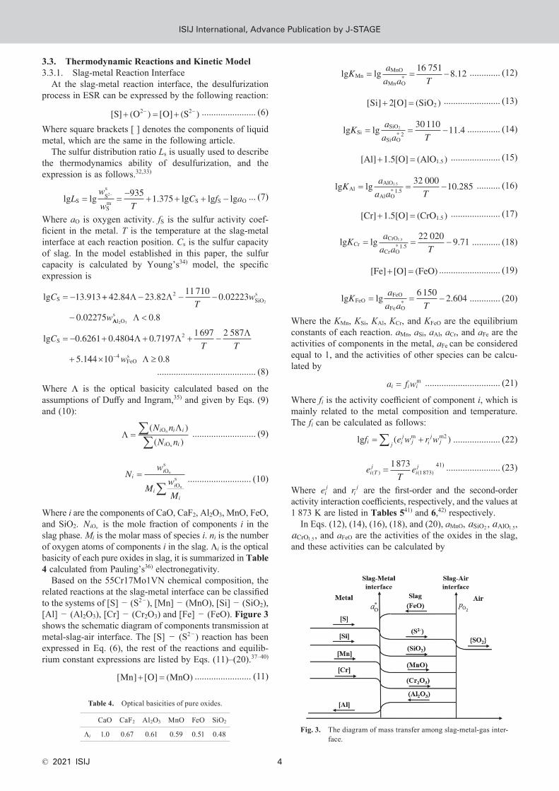
Based on the 55Cr17Mo1VN chemical composition, the related reactions at the slag-metal interface can be classified to the systems of [S] − (S2−), [Mn] − (MnO), [Si] − (SiO2), [Al] − (Al2O3), [Cr] − (Cr2O3) and [Fe] − (FeO). Figure 3 shows the schematic diagram of components transmission at metal-slag-air interface. The [S] − (S2−) reaction has been expressed in Eq. (6), the rest of the reactions and equilib-rium constant expressions are listed by Eqs. (11)–(20).37–40)
[ ] [ ] ( )Mn O MnO� � ........................ (11)
lg lg16 751
8.12MnMnO
Mn O*
Ka
a a T� � � ............. (12)
[ ] [ ] ( )Si O SiO� �2 2 ........................ (13)
lg lgSiSiO
Si O* 22K
a
a a� � �
30 11011 4
T. .............. (14)
[ ]Al 1.5[O] (AlO )1.5� � ..................... (15)
lg lgAlAlO
Al O* 1.5
1.5Ka
a a� �
32 00010 285
T� . .......... (16)
[ ]Cr 1.5[O] (CrO )1.5� � ..................... (17)
lg lgCrCrO
Cr O* 1.5
1.5Ka
a a� �
22 0209.71
T� ............ (18)
[ ]Fe [O] (FeO)� � .......................... (19)
lg lgFeOFeO
Fe O*
Ka
a a� � �
6 1502 604
T. ............. (20)
Where the KMn, KSi, KAl, KCr, and KFeO are the equilibrium constants of each reaction. aMn, aSi, aAl, aCr, and aFe are the activities of components in the metal, aFe can be considered equal to 1, and the activities of other species can be calcu-lated by
a f wi i i= m ................................ (21)
Where fi is the activity coefficient of component i, which is mainly related to the metal composition and temperature. The fi can be calculated as follows:
lg ( )m m2f e w r wi ij
j ij
jj�� � .................... (22)
eT
ei Tj
ij
( ) (1873)1873
= 41) ....................... (23)
Where eij and ri j are the first-order and the second-order activity interaction coefficients, respectively, and the values at 1 873 K are listed in Tables 541) and 6,42) respectively.
In Eqs. (12), (14), (16), (18), and (20), aMnO, aSiO2 , aAlO1.5, aCrO1.5, and aFeO are the activities of the oxides in the slag, and these activities can be calculated by
Table 4. Optical basicities of pure oxides.
CaO CaF2 Al2O3 MnO FeO SiO2
Λi 1.0 0.67 0.61 0.59 0.51 0.48 Fig. 3. The diagram of mass transfer among slag-metal-gas inter-face.
ISIJ International, Advance Publication by J-StageISIJ International, Advance Publication by J-STAGE
ISIJ International, Vol. 61 (2021), No. 1
© 2021 ISIJ5
a Ni i in n nO O O� � ............................ (24)
Where Ni nO is the mole fraction of component i in the slag. γ i nO is the Raoult activity coefficient of component i in the slag which is given by Eqs. (25)–(29):43)
lg 0.25FeO CaO SiO AlO CrO
SiO
2 1.5 1.5� � �
�
11800
3 562T
N N N N
TN
( )� 0.45
22 1.5 2 1.5
1.5
AlO MnO SiO CrO
MnO AlO
NT
N N N
TN N
�
�
4 916
123 1
( )� 0.45
+9778
TN NSiO AlO2 1.5
........................................ (25)
lg 0.45MnO� �� � �lg FeO SiO CrO AlO2 1.5 1.5
4 916 123
TN N
TN( )�
........................................ (26)
lg
0.45
SiO2� �� � �
� �
lg FeO CaO MnO
AlO1.5
11800 4 916
3 562 1 978T
NT
N
TN
TNNCrO1.5
..... (27)
lg� �Al FeO CaO SiO MnO2 3 2O � � � �lg2 950 3 562 123
TN
TN
TN
........................................ (28)
lg
5 310 2 212� �CrO FeO CaO MnO SiO1.5 2lg
1 978� � � �
T TN
TNN
........................................ (29)
Based on the relationship between the molar fraction and the mass fraction, the expressions of the equilibrium con-stants of the slag-metal reaction are converted to obtain the expressions of the equilibrium Li of the species i at the slag-metal interface. Finally, Li is expressed as Eqs. (30)–(34):
L
w
w
K M fw
M a
i
ii
n
MnMnOs *
Mnm *
Mn MnO MnOs
MnOO*� �
�
� ........ (30)
L
w
w
K M fw
M a
i
ii
n
SiSiOs *
Sim *
Si SiO SiOs
SiOO*22
2
2
� ��
� .......... (31)
L
w
w
K M fw
M a
i
ii
n
AlAl Os *
Alm *
Al AlO AlOs
AlOO*1.52 3
1.5
1.5
� ��
� ....... (32)
L
w
w
K M fw
M a
i
ii
n
CrCr Os *
Crm *
Cr CrO CrOs
CrOO*1.52 3
1.5
1.5
� ��
� ....... (33)
L w
K Mw
M a
i
ii
n
FeO FeOs *
FeO FeOOs
FeOO*� �
�
� ........... (34)
We can obtain the relationship of the content of species i with time by substituting each Li into Eq. (2). When Ls is substituted and the integral transformation is performed, the expression for wS
m is shown in Eq. (35), and expressions for other components are similar to wS
m .
w
A
Vk t w
w
L
w
LSm
mS*
Sm,o S
w,o
S
Sw,o
S
exp2 2
� � � � �� ��
��
����
���
�
���
..... (35)
Correspondingly, the mass transfer rate equations of the relevant components in the slag can be acquired. Finally, in the desulfurization kinetic Eq. (35), only the aO
* is unknown parameters at each reaction position. Therefore, the desul-furization kinetic Eq. (35) can be regarded as a function of aO
* . According to the mass balance of oxygen between slag and metal, Eq. (36) can be obtained.
1
M
d
d
2
M
d
d
1.5
M
d
d
1.5
M
d
d
1
M
d
Mn
Mnm
Si
Sim
Al
Alm
Cr
Crm
S
S
w
t
w
t
w
t
w
t
w
� � �
�mm
FeO
FeOs
d
1
M
d
dt
w
t�
..... (36)
The left-hand side of Eq. (36) is the consumption rate of oxygen to the slag-metal interface, and the right-hand side is the supply rate of oxygen to the slag-metal interface.
3.3.2. Slag-air Reaction InterfaceIn the Exp1 experimental condition, due to gas-phase
desulfurization, ESR generally has a higher desulfurization rate in theory. Reactions (37) and (38) occur at the slag-gas interface, which decreases the sulfur content and promote the desulfurization process in the slag.
(S )1
2{O } {S } (O )2
2 22� �� � � ................. (37)
1
2{S } {O } {SO }2 2 2� � ...................... (38)
The desulfurization reaction rate at the slag-gas interface has been given by the Eq. (5). Substituting Eq. (5) integrals into Eq. (35), the change rule of sulfur content in steel under air atmosphere can be calculated by follows:
w
A
Vk t w
w w
L
wSm
mS*
Sm,o S
s,oSs
S
Ss,
exp2 2 2
� � � ��
�� � ��
��
����
���
�
���
ooSs
S
2� �w
L
........................................ (39)
To calculate the sulfur content changes during the ESR process under different atmospheres, the following types of data are required: thermodynamic data, kinetic data, geo-metric data, etc.
Table 5. The first-order interaction coefficients eij used in this study.
eij C Si Mn P S Al O
S 0.111 0.075 −0.026 0.035 0.018 0.041 –
Mn −0.0538 −0.0327 – −0.0035 −0.048 – −0.083
Si 0.24 0.37 0.002 0.11 0.056 0.07 −0.23
Al 0.091 0.06 – – 0.049 0.048 −6.60
Table 6. The second-order interaction coefficients ri j used in this study.
rij C Si P S Al Mn
S 0.0058 0.0017 0.0006 −0.0009 0.0009 –
ISIJ International, Advance Publication by J-StageISIJ International, Advance Publication by J-STAGE
ISIJ International, Vol. 61 (2021), No. 1
© 2021 ISIJ 6
3.4. Model Parameters3.4.1. Reaction Temperature
The liquidus temperature of 55Cr17Mo1VN plastic die steel can be calculated by Thermo-calc: Tliquidus = 1 720 K. According to related reference,44) the temperature of the electrode tip/slag interface is generally higher than the liquidus temperature by 20–30 K, assumed that the reaction temperature at this position is 1 750 K. Furthermore, when the droplet formed from at the electrode tip to pass through the slag layer, it is continuously heated by the slag and the temperature of the droplet reaches 1 960 K. The temperature at the slag-metal pool is taken as 1 895 K.
3.4.2. Mass Transfer CoefficientsAccording to the permeation theory, the expressions mass
transfer coefficients of the metal side and slag at each reac-tion stage can be obtained from Eqs. (40) and (41), respec-tively. Where the Di
m and Di nOs are diffusion coefficients of i
and iOn in metal and slag side, the DSm and DS
s can be taken as (0.0068T − 10.46) × 10−4 cm2/s and 3.8 × 10⁻⁴ cm2/s according to the reference;24) te is contact reaction time. The te at the electrode tip can be calculated by Eq. (42).45)
kD
ti
i
e
� 2m
� .............................. (40)
k
D
ti
i
en
nO
Os
2��
............................ (41)
tQ
re
m
m
m
� 3.352 cos
3 g sin cos
2/3 1/3E
5/3� � �� � �
�
��
�
��
�
��
�
��
���
��� ... (42)
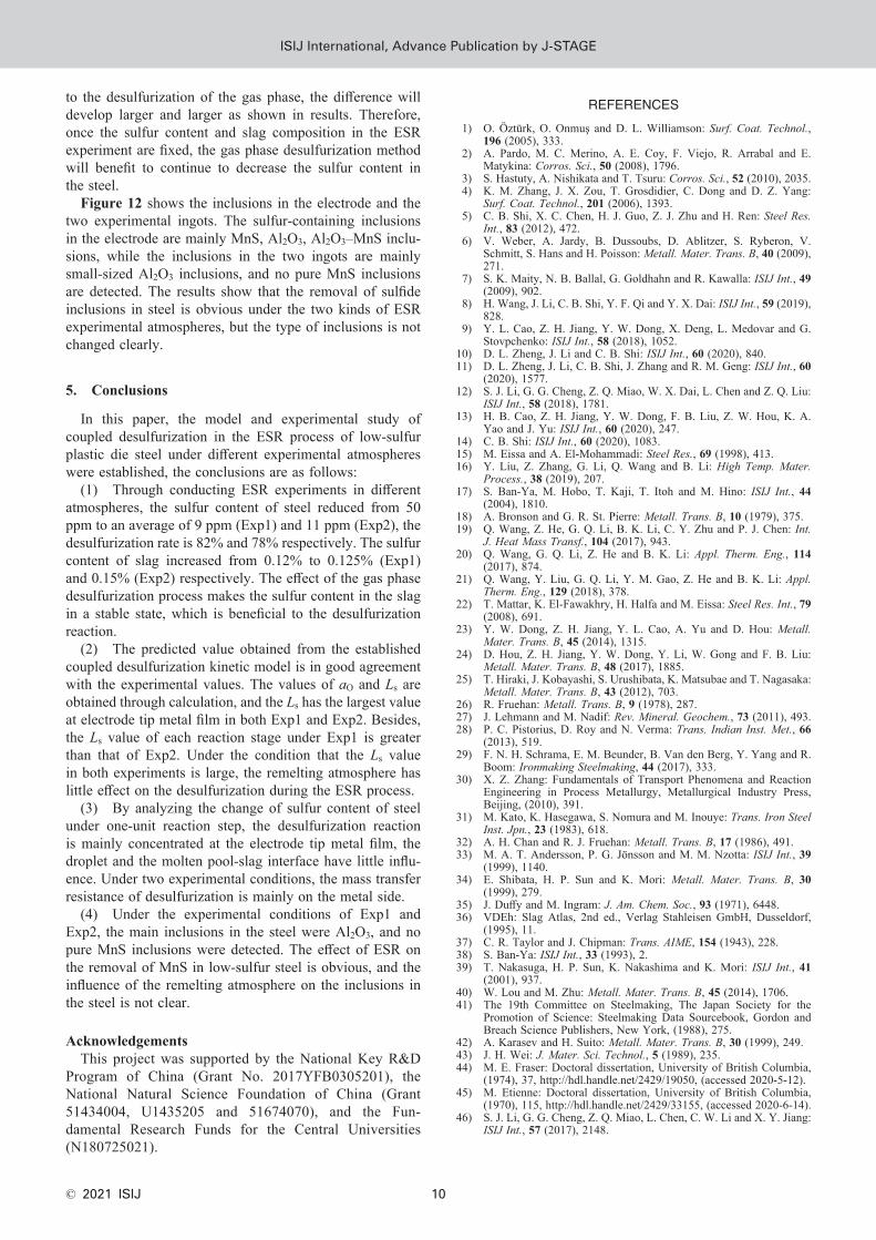
Where, θ is the taper angle of the electrode tip, as shown in Fig. 4, Qm is the volume remelting rate. μm is the viscosity of the metal. rE is the radius of the consumable electrode. To make the calculation more accurate, the electrode was immediately lifted after the experiments, as shown in Fig. 4(b), and the simplified diagram is shown in Fig. 4(a). After calculation, te = 1.02 s at electrode tip. According to the reference,24) the average velocity of metal droplets passing through the slag layer is 31 cm/s, and the velocity of the molten slag at the droplet is taken as 10 cm/s. Combining the height of the molten slag and the electrode immersed depth, the te for the droplet to pass through the slag layer can be cal-culated, 0.19 s. Further, the mass transfer coefficient at each position can be obtained by Eqs. (40) and (41). At the slag-air interface, according to the reference,31) ksg = 0.01 cm/s.
3.4.3. Area/Volume RatioAt the electrode tip, according to Fig. 4(a), the area and
volume of the metal film can be estimated by the following Eqs. (43) and (44):
A
r
f ��
�� �
��
E
2
22coscos
54.39 cm
���
��� ............ (43)
Vr
f � �� �
�E2
3sin3
0.54 cm ................... (44)
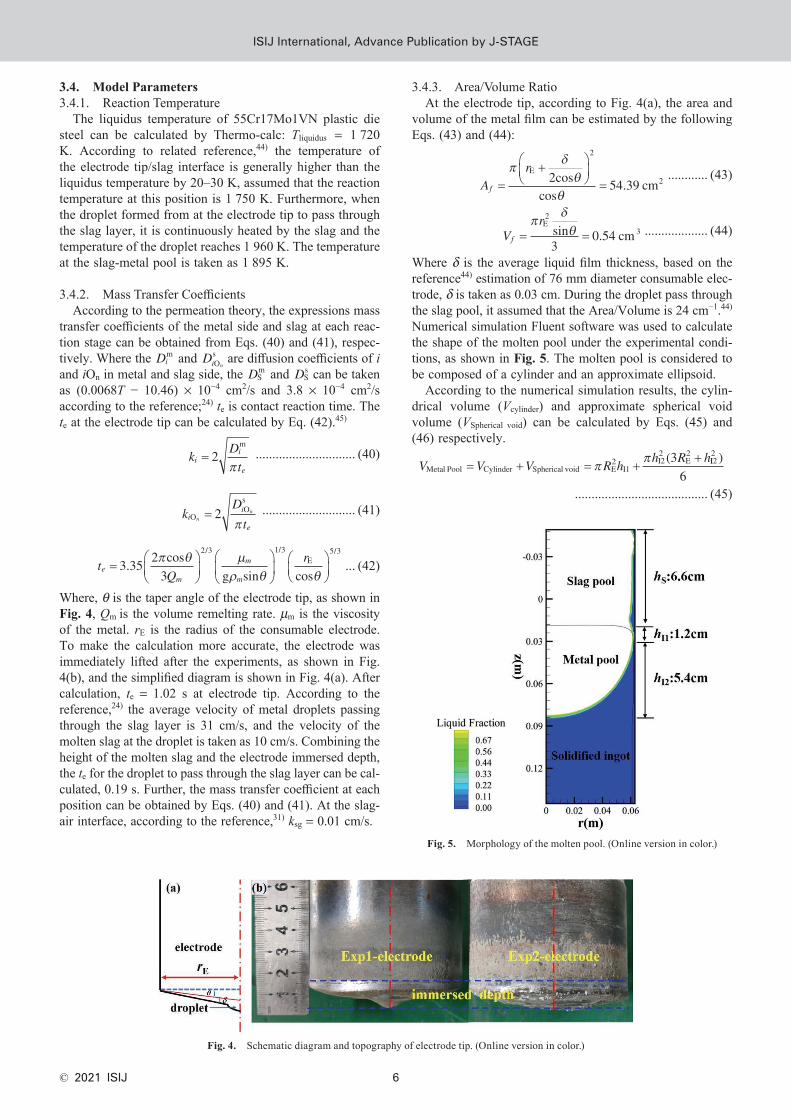
Where δ is the average liquid film thickness, based on the reference44) estimation of 76 mm diameter consumable elec-trode, δ is taken as 0.03 cm. During the droplet pass through the slag pool, it assumed that the Area/Volume is 24 cm−1.44) Numerical simulation Fluent software was used to calculate the shape of the molten pool under the experimental condi-tions, as shown in Fig. 5. The molten pool is considered to be composed of a cylinder and an approximate ellipsoid.
According to the numerical simulation results, the cylin-drical volume (Vcylinder) and approximate spherical void volume (VSpherical void) can be calculated by Eqs. (45) and (46) respectively.
V V V R hh R h
Metal Pool Cylinder Spherical void E2
I1I22
E23
� � � ��
�� ( II2
2
6
)
........................................ (45)
Fig. 4. Schematic diagram and topography of electrode tip. (Online version in color.)
Fig. 5. Morphology of the molten pool. (Online version in color.)
ISIJ International, Advance Publication by J-StageISIJ International, Advance Publication by J-STAGE

ISIJ International, Vol. 61 (2021), No. 1
© 2021 ISIJ7
A RMetal Pool E2� � ........................... (46)
Where hI1 is the height of the cylindrical section. hI2 is the height of the spherical void section. RE is the internal radius of the ESR mold. During the ESR process, since the electrode is immersed in the slag pool, the slag-air contact interface can be regarded as a ring, which can be calculated on the basis of the following equation.
A R rg E2
E2� �� ( ) ........................... (47)
The volume of slag can be calculated according to the quality and density of the slag. When the ρs = 2.6 g/cm3, the calculated slag volume is 1 320 cm3.
So far, the relevant parameters in the desulfurization kinetic model have been solved and summarized in Table 7. Only the mass transfer coefficients of sulfur in slag and steel are listed in the table, and the solution method of mass transfer coefficients of other components is similar.
Figure 6 shows the flow chart of the overall solution in the framework of the desulfurization kinetics model under dif-ferent atmospheres, which is calculated by Matlab software.
4. Calculated Results and Discussion
Figure 7 shows the variation of sulfur content in steel and slag with remelting time. The results display that the predicted values of the model are in good agreement with the experimentally measured values. As shown in Fig. 7(a), the sulfur content in Exp1 is reduced from 50 ppm of the original consumable electrode to 6–10 ppm, and it is
reduced to 7–12 ppm in Exp2. The sulfur content in the slag increased from 0.12% to 0.125% under Exp1 experimental conditions and increased to 0.15% under Exp2 experimen-tal conditions as displayed in Fig. 7(b). Judging from the simulated values under the two experimental conditions in detail, the initial sulfur content is close, which is due to the strong desulfurization ability of slag in the early stage of the ESR process. In the beginning, although the remelt-ing atmosphere was different, the sulfur content in the slag was equivalent, and the effect of the atmosphere was not obvious at the beginning of the remelting. Therefore, the desulfurization capacity of the slag was roughly equal in both experiments. With the extension of ESR time, under
Fig. 6. Overall solution schematic of the desulfurization kinetics model.
Table 7. Related parameters in the desulfurization kinetic model.
ParametersReaction positions
electrode tip/slag
droplet/slag
metal pool/slag slag/air
ks, cm/s 0.0167 0.037 0.0069 –
kS2− , cm/s 0.027 0.06 0.008 0.01
Reaction area, cm2 54.39 – 273 89
Liquid volume, cm3 0.54 – 910 1 250
Area/volume, cm −1 100 24 0.3 0.07
Reaction time, s 1.02 0.19 – tmelt
Fig. 7. Variation of sulfur content in steel and slag with remelting time. (Online version in color.)
ISIJ International, Advance Publication by J-StageISIJ International, Advance Publication by J-STAGE

ISIJ International, Vol. 61 (2021), No. 1
© 2021 ISIJ 8
the condition of Exp1, the sulfur in the slag is continuously discharged into the atmosphere in the form of SO2 based on the reactions (37) and (38). As shown in Fig. 7(b), from the beginning to the ending of the ESR process, the calculated results show that the sulfur content in the slag is roughly unchanged. However, due to the lack of gas-phase desulfurization conditions in Exp2, the sulfur content in the slag continues to accumulate, and the desulfurization effect is weakened.
To compare the effect of the atmosphere on the changes in aO and Ls, the model was used to calculate the variation and the results are shown in Fig. 8. The results reveal that the desulfurization effect of the three stages from the end of the electrode, the droplet passing through the slag layer, and the molten pool-slag pool reaction interfaces are dif-ferent. The oxygen activity at the electrode tip is the low-est, and its value is less than 10 −5, but the oxygen activity under the two experimental conditions is roughly equal at the same reaction position as shown in Fig. 8(a). This result indicates that the influence of the atmosphere on the internal metal-slag reaction is not obvious. Furthermore, the calculation result of Ls is given in Fig. 8(b), the highest Ls value reached 800 under Exp1 conditions and 700 under Exp2 experimental conditions at the beginning. Although the value of Ls decreases continuously with the increase of remelting time, it always has the maximum value at the tip of the electrode melt film. The above results indicate that the desulfurization capacity is the strongest at the electrode tip under two experimental conditions, and the desulfurization capacity under the air atmosphere is slightly greater than that under the protective atmosphere.
Since the Ls value under both experimental conditions is very huge, the Eqs. (35) and (39) can be approximately written as the Eq. (48). At this point, it can be considered that the sulfur content in the molten steel depends on the initial sulfur content, which further explains under the two experimental conditions, the initial sulfur content is the same. Besides, under this condition, the initial sulfur content is the minimum sulfur content. However, with the increase of the remelting time, the oxygen activities at each reaction sites all tend to increase. Correspondingly, the distribution coefficient of sulfur between the slag and metal decreases, and the desulfurization capacity is rela-tively weakened. But even at the end of the ESR process,
the Ls values at the metal film of the electrode tip are 400 and 350, respectively, so the desulfurization ability is still obvious.
wA
Vk t wS
m
mS*
Sm,oexp� � ��
��
��� ................... (48)
Figure 9 shows the changing trend of the sulfur content during one-unit reaction step from the metal film of the electrode tip to the metal pool. The model result shows good agreement with the measured values. At the initial reaction state, according to the previous analysis, there is no significant difference in the desulfurization effect under the two experimental conditions. At the beginning of the ESR process, the model predicts that the sulfur content decrease from 0.005% to 0.0009% at the metal film, and a slight change occurs when the droplet passes through the slag layer. The same trend was observed at the end of the ESR process under two experiments. The above results show that the desulfurization reaction is mainly concentrated at the metal film at the end of the electrode, and the role of the droplet and the molten pool is not significant. Further analysis, according to the calculation results in Table 7, the area/volume ratio has a larger value at the metal film than other reaction sites, which possesses better kinetic reaction
Fig. 8. Time-dependent relationship between aO and Ls at different reaction positions. (Online version in color.)
Fig. 9. Variation trend of sulfur content during one-unit step. (Online version in color.)
ISIJ International, Advance Publication by J-StageISIJ International, Advance Publication by J-STAGE

ISIJ International, Vol. 61 (2021), No. 1
© 2021 ISIJ9
conditions, so the electrode tip desulfurization ability is the strongest. This phenomenon is similar to the reference46) research on the changes in oxygen and aluminum elements during the ESR process.
Since the desulfurization resistance has an important effect on the ESR desulfurization process, the desulfuriza-tion resistance on the molten steel side and the slag side can be calculated from 1/ks and � �m k L/ ( )s s s2� respectively based on the Eq. (3). Figure 10 shows the results of 1/ks and � �m k L/ ( )s s s2� values variation at each reaction position under different atmospheres. Since the electrode composi-tion, slag height, and electrode immersion depth used in the two experiments are samely, according to Eq. (40), the corresponding mass transfer coefficient of sulfur is equal. As shown in Fig. 10(a), the mass transfer resistance of sulfur on the metal side is alike, and the mass transfer resistance of sulfur at the interface of the metal pool-slag pool is the largest. As shown in Fig. 10(b), since the Ls is larger in Exp (1), the � �m k L/ ( )s s s2� value is smaller. Also, the mass transfer resistance at the position where the slag contacts the electrode tip is the smallest. Through comparison, it can be observed that the mass transfer resistance of sulfur in the metal side is much greater than that in the slag side during the process of the metal film, droplet, and metal pool. The limit of desulfurization steps in both experiments is on the metal side. By further reducing the sulfur content in the initial electrode will facilitate the desulfurization process during the ESR process.
The mass transfer resistance of sulfur on metal and slag sides determines the comprehensive mass transfer coef-ficient of sulfur ( s
*k ), and the calculated results are given in Fig. 11. At different reaction positions, the ks
* tends to decrease as the remelting time increases. The ks
* in the air atmosphere is larger than in the protective atmosphere. Due
Fig. 10. Mass transfer resistance of sulfur on metal side and slag side. (Online version in color.)
Fig. 11. Comprehensive mass transfer coefficient of sulfur. (Online version in color.)
Fig. 12. The SEM mappings of inclusions in electrode and ingots. (Online version in color.)
ISIJ International, Advance Publication by J-StageISIJ International, Advance Publication by J-STAGE
ISIJ International, Vol. 61 (2021), No. 1
© 2021 ISIJ 10
to the desulfurization of the gas phase, the difference will develop larger and larger as shown in results. Therefore, once the sulfur content and slag composition in the ESR experiment are fixed, the gas phase desulfurization method will benefit to continue to decrease the sulfur content in the steel.
Figure 12 shows the inclusions in the electrode and the two experimental ingots. The sulfur-containing inclusions in the electrode are mainly MnS, Al2O3, Al2O3–MnS inclu-sions, while the inclusions in the two ingots are mainly small-sized Al2O3 inclusions, and no pure MnS inclusions are detected. The results show that the removal of sulfide inclusions in steel is obvious under the two kinds of ESR experimental atmospheres, but the type of inclusions is not changed clearly.
5. Conclusions
In this paper, the model and experimental study of coupled desulfurization in the ESR process of low-sulfur plastic die steel under different experimental atmospheres were established, the conclusions are as follows:
(1) Through conducting ESR experiments in different atmospheres, the sulfur content of steel reduced from 50 ppm to an average of 9 ppm (Exp1) and 11 ppm (Exp2), the desulfurization rate is 82% and 78% respectively. The sulfur content of slag increased from 0.12% to 0.125% (Exp1) and 0.15% (Exp2) respectively. The effect of the gas phase desulfurization process makes the sulfur content in the slag in a stable state, which is beneficial to the desulfurization reaction.
(2) The predicted value obtained from the established coupled desulfurization kinetic model is in good agreement with the experimental values. The values of aO and Ls are obtained through calculation, and the Ls has the largest value at electrode tip metal film in both Exp1 and Exp2. Besides, the Ls value of each reaction stage under Exp1 is greater than that of Exp2. Under the condition that the Ls value in both experiments is large, the remelting atmosphere has little effect on the desulfurization during the ESR process.
(3) By analyzing the change of sulfur content of steel under one-unit reaction step, the desulfurization reaction is mainly concentrated at the electrode tip metal film, the droplet and the molten pool-slag interface have little influ-ence. Under two experimental conditions, the mass transfer resistance of desulfurization is mainly on the metal side.
(4) Under the experimental conditions of Exp1 and Exp2, the main inclusions in the steel were Al2O3, and no pure MnS inclusions were detected. The effect of ESR on the removal of MnS in low-sulfur steel is obvious, and the influence of the remelting atmosphere on the inclusions in the steel is not clear.
AcknowledgementsThis project was supported by the National Key R&D
Program of China (Grant No. 2017YFB0305201), the National Natural Science Foundation of China (Grant 51434004, U1435205 and 51674070), and the Fun-damental Research Funds for the Central Universities (N180725021).
REFERENCES
1) O. Öztürk, O. Onmuş and D. L. Williamson: Surf. Coat. Technol., 196 (2005), 333.
2) A. Pardo, M. C. Merino, A. E. Coy, F. Viejo, R. Arrabal and E. Matykina: Corros. Sci., 50 (2008), 1796.
3) S. Hastuty, A. Nishikata and T. Tsuru: Corros. Sci., 52 (2010), 2035.4) K. M. Zhang, J. X. Zou, T. Grosdidier, C. Dong and D. Z. Yang:
Surf. Coat. Technol., 201 (2006), 1393.5) C. B. Shi, X. C. Chen, H. J. Guo, Z. J. Zhu and H. Ren: Steel Res.
Int., 83 (2012), 472.6) V. Weber, A. Jardy, B. Dussoubs, D. Ablitzer, S. Ryberon, V.
Schmitt, S. Hans and H. Poisson: Metall. Mater. Trans. B, 40 (2009), 271.
7) S. K. Maity, N. B. Ballal, G. Goldhahn and R. Kawalla: ISIJ Int., 49 (2009), 902.
8) H. Wang, J. Li, C. B. Shi, Y. F. Qi and Y. X. Dai: ISIJ Int., 59 (2019), 828.
9) Y. L. Cao, Z. H. Jiang, Y. W. Dong, X. Deng, L. Medovar and G. Stovpchenko: ISIJ Int., 58 (2018), 1052.
10) D. L. Zheng, J. Li and C. B. Shi: ISIJ Int., 60 (2020), 840.11) D. L. Zheng, J. Li, C. B. Shi, J. Zhang and R. M. Geng: ISIJ Int., 60
(2020), 1577.12) S. J. Li, G. G. Cheng, Z. Q. Miao, W. X. Dai, L. Chen and Z. Q. Liu:
ISIJ Int., 58 (2018), 1781.13) H. B. Cao, Z. H. Jiang, Y. W. Dong, F. B. Liu, Z. W. Hou, K. A.
Yao and J. Yu: ISIJ Int., 60 (2020), 247.14) C. B. Shi: ISIJ Int., 60 (2020), 1083.15) M. Eissa and A. El-Mohammadi: Steel Res., 69 (1998), 413.16) Y. Liu, Z. Zhang, G. Li, Q. Wang and B. Li: High Temp. Mater.
Process., 38 (2019), 207.17) S. Ban-Ya, M. Hobo, T. Kaji, T. Itoh and M. Hino: ISIJ Int., 44
(2004), 1810.18) A. Bronson and G. R. St. Pierre: Metall. Trans. B, 10 (1979), 375.19) Q. Wang, Z. He, G. Q. Li, B. K. Li, C. Y. Zhu and P. J. Chen: Int.
J. Heat Mass Transf., 104 (2017), 943.20) Q. Wang, G. Q. Li, Z. He and B. K. Li: Appl. Therm. Eng., 114
(2017), 874.21) Q. Wang, Y. Liu, G. Q. Li, Y. M. Gao, Z. He and B. K. Li: Appl.
Therm. Eng., 129 (2018), 378.22) T. Mattar, K. El-Fawakhry, H. Halfa and M. Eissa: Steel Res. Int., 79
(2008), 691.23) Y. W. Dong, Z. H. Jiang, Y. L. Cao, A. Yu and D. Hou: Metall.
Mater. Trans. B, 45 (2014), 1315.24) D. Hou, Z. H. Jiang, Y. W. Dong, Y. Li, W. Gong and F. B. Liu:
Metall. Mater. Trans. B, 48 (2017), 1885.25) T. Hiraki, J. Kobayashi, S. Urushibata, K. Matsubae and T. Nagasaka:
Metall. Mater. Trans. B, 43 (2012), 703.26) R. Fruehan: Metall. Trans. B, 9 (1978), 287.27) J. Lehmann and M. Nadif: Rev. Mineral. Geochem., 73 (2011), 493.28) P. C. Pistorius, D. Roy and N. Verma: Trans. Indian Inst. Met., 66
(2013), 519.29) F. N. H. Schrama, E. M. Beunder, B. Van den Berg, Y. Yang and R.
Boom: Ironmaking Steelmaking, 44 (2017), 333.30) X. Z. Zhang: Fundamentals of Transport Phenomena and Reaction
Engineering in Process Metallurgy, Metallurgical Industry Press, Beijing, (2010), 391.
31) M. Kato, K. Hasegawa, S. Nomura and M. Inouye: Trans. Iron Steel Inst. Jpn., 23 (1983), 618.
32) A. H. Chan and R. J. Fruehan: Metall. Trans. B, 17 (1986), 491.33) M. A. T. Andersson, P. G. Jönsson and M. M. Nzotta: ISIJ Int., 39
(1999), 1140.34) E. Shibata, H. P. Sun and K. Mori: Metall. Mater. Trans. B, 30
(1999), 279.35) J. Duffy and M. Ingram: J. Am. Chem. Soc., 93 (1971), 6448.36) VDEh: Slag Atlas, 2nd ed., Verlag Stahleisen GmbH, Dusseldorf,
(1995), 11.37) C. R. Taylor and J. Chipman: Trans. AIME, 154 (1943), 228.38) S. Ban-Ya: ISIJ Int., 33 (1993), 2.39) T. Nakasuga, H. P. Sun, K. Nakashima and K. Mori: ISIJ Int., 41
(2001), 937.40) W. Lou and M. Zhu: Metall. Mater. Trans. B, 45 (2014), 1706.41) The 19th Committee on Steelmaking, The Japan Society for the
Promotion of Science: Steelmaking Data Sourcebook, Gordon and Breach Science Publishers, New York, (1988), 275.
42) A. Karasev and H. Suito: Metall. Mater. Trans. B, 30 (1999), 249.43) J. H. Wei: J. Mater. Sci. Technol., 5 (1989), 235.44) M. E. Fraser: Doctoral dissertation, University of British Columbia,
(1974), 37, http://hdl.handle.net/2429/19050, (accessed 2020-5-12).45) M. Etienne: Doctoral dissertation, University of British Columbia,
(1970), 115, http://hdl.handle.net/2429/33155, (accessed 2020-6-14).46) S. J. Li, G. G. Cheng, Z. Q. Miao, L. Chen, C. W. Li and X. Y. Jiang:
ISIJ Int., 57 (2017), 2148.
ISIJ International, Advance Publication by J-StageISIJ International, Advance Publication by J-STAGE